

Page 1
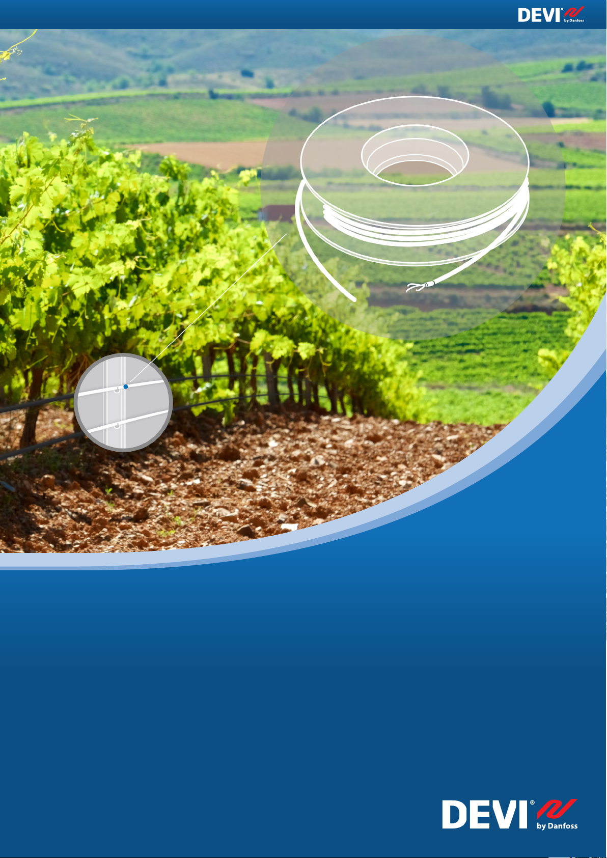
Electric Heating
Vineyards
Frost Protection
Application guide
Intelligent solutions
with lasting effect
Visit devi.com
Page 2
Page 3

Index
Our quality management
system
and compliances
Along with full compliance with EU
directives and product approvals
ISO 9001 TS 16949
ISO 14001 PED
1. Application overview 4
2. System description 5
3. System design 6
3.1 Heat loss calculation 6
3.2 System output 6
3.3 Product selection 7
3.3.1 Heating cable selection 7
3.3.2 Thermostats/controllers 9
3.3.3 Accessories 11
3.4 Installation guide 12
4. Safety instruction 13
4.1 DO's 13
4.2 DON'Ts 13
Solve the challenge of vine
growers with an Electric
Heating system
Electric Heating by Danfoss is a symbiosis of long history formed by 2 brands
DEVI and Danfoss united under 1 company umbrella.
It derives from DEVI brand that was established in Copenhagen, Denmark, in
1942. As from January 1st 2003 DEVI has become a part of the Danfoss Group Denmark's largest industrial Group.
Danfoss is one of the world's leading companies within heating, cooling and air
conditioning. The Danfoss Group has more than 23.000 employees and serves
customers in more than 100 countries. The development of electric heating
systems takes place in Denmark, where the head office is situated while
heating elements (cables and mats) are manufactured by Danfoss in EU.
5. Case stories 14
6. Technical support 14
Electric Heating is an energy efficient system
using electric heating cables to protect vines
against frost damage
This design guide presents our recommendations for design and installation
of Vineyards Frost Protection system. It provides guidance for a heating cable
layout, electric data and system configurations.
Following our recommendations will ensure energy efficient,
reliable and maintenance free solution for constant wattage
heating cables with 20 year warranty.
Page 4
1. Application
overview
Every year vine growers from
different regions face a problem
of late frosts. They often happen
in April - May when buds start
blossoming.Late spring frosts are
one of the greatest challenges vine
growers are facing. Non-heated vines
can suffer considerable inflorescence
damages (up to 50%), whilst heated
vines will have dramatically
improved protection of harvest loss
or damage and reduce the losses to
approximately 13-20%.
Worldwide, the grape and wine
industry rely on three main
alternatives for frost protection: frost
fans, sprinklers, and candles.
Electric Heating solves the challenge
with energy efficient systems using
Electric Heating cables to protect
vines against frost damage.
Benefits
• An energy-efficient solution with electric
heating cables.
• Easy, fast and reliable installation.
• A customized approach to meet client’s needs,
area of vinery and number of rows.
• Proven high saving compared to the existing
methods.
• A sustainable solution for a green and clean
future through low energy consumption during
the frost period.
• Tough cable outer sheath (resistant to weather
and UV)
A green (without CO2 emissions)
and sustainable lifetime solution.
Highly economic due to low energy
consumption during the frosts
period.
• Protected against chemical
fertilizers;
• Extremely-high pulling strength
(special tractors coward the
vineyards, while knocking the
fruits);
• Accurate power design (W)
according to requested needs;
• 5 or 20 years warranty.
Heating system can provide frost
protection ONLY in spring season
when the bud grows and NOT in
wintertime!
4 Application guide · Vineyards Frost Protection · ©DEVI
Page 5
2. System description
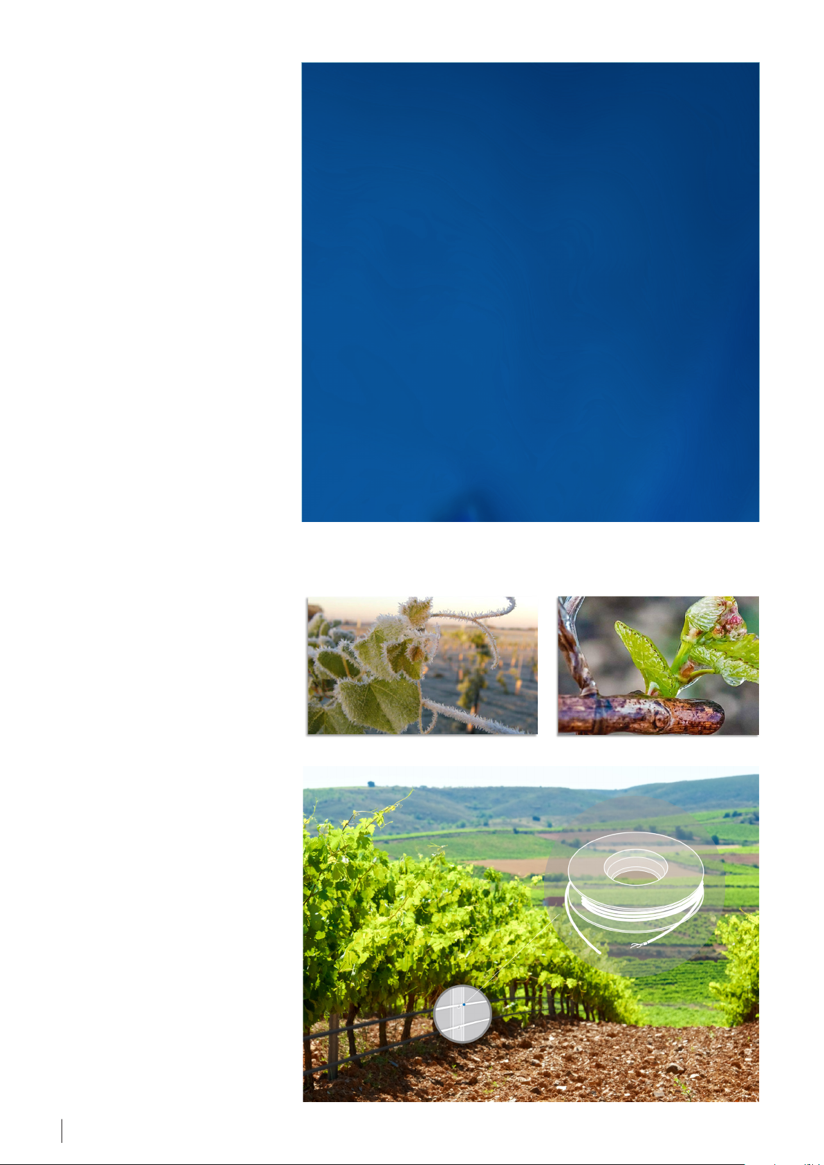
The concept involves
installation of heating cable
along the main trellising wire
of grapevines.
• Frosts protection in
spring time (from 2 up to
7 days)
• The ambient
temperature is -2…-8 °С
• Most susceptible to frost
vineyards are located in
the lowlands/valleys (low
area of land)
50%
100%
40%
30%
20%
10%
Electric Heating solves the challenge
with energy efficient systems using
Electric Heating cables to protect
A dormant bud is reasonably frost
hardy, it can survive frost down to
-3,5 °С (Pinot Noir).
vines against spring frost damage.
The heating cables by DEVI are installed and fixed on metal wire along
the grapes. The system is controlled
automatically by temperature sensors
As the bud grows the water contents
raise in the bud and it becomes more
susceptible to frost -1,1 °С can damage it (Pinot Noir).
connected to the controller.
We offer an energy-efficient solution
Non-heated vines can suffer considerable inflorescence (bud) losses.
with our electric heating cables for
frost protection of the vines.
Number of berries can decrease by 3
times or completely disappear!
Different grape varieties can withstand frosts different.
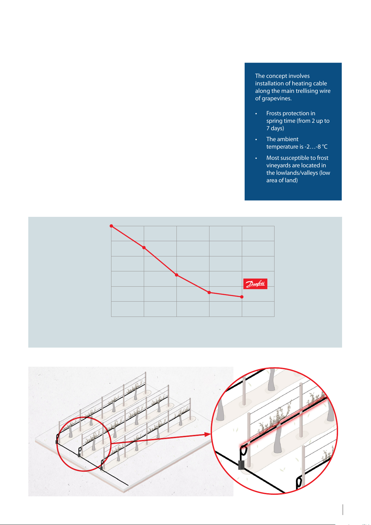
Depending on heating level, vintage losses may be decreased
. . .
46%
Common view of electric heating system for vineyards
Vintage losses, %
0%
Non heated
Slightly
heated
28%
heated
Averagely
16%
13%
heated
Efficiently
Well-heated
5Application guide · Vineyards Frost Protection · ©DEVI
Page 6

3. System design
• Tolerance of heating cable resistance: +10%...-5%;
• Cable length tolerance: +2%...-2%;
• Supply voltage: +5%...-5%.
Totally can be up to 30%
Following pages provide an easy design guide for selection of a Vineyards frost protection system.
The recommendations are provided relates to heating cables, as well as thermostats and accessories.
3.1 Heat loss calculation
Linear output of a heating cable
(W/m), which is installed for main
vine branch, should be at least the
same as heat loss (Q, W/m).
In order to calculate heat losses and
design the system, we need to know:
• Minimum ambient temperature in
spring frost period (-2…-8 °С);
• Grape sort. For different sorts
we need to maintain different
temperature (+1…+5 °С). The
temperature must be checked with
vineyard owner and specified for
the project calculation;
• Length and numbers of vineyard
rows;
• Available total load on site, kW;
• Voltage (230, 400 V).
For medium weather conditions*,
In average can be installed from 10 up
to 20 W/m for each main branch of
grapevine.
Example.
Location is France and ambient
temperature during frosts period is
-8 °С. Grape sort is Pinot Noir and we
can maintain +2 °С near the main
vine branch.
According to the data above:
q
= Δt
sys
q
t
Δt
sys
main
= t
main.-amb.
- t
main.
amb.
q
= 10 · 1 = 10 W/m
sys
– heat loss of the system, W/m.
. – maintain temperature near the
· p
main.-amb.
= +2 – (–8) = 10 °С
vines, °С.
t
– ambient temperature, °С.
amb.
p – output coefficient, W/(m · °С).
in order to increase temperature by
1 °С needs power of approx. 1 Watt.
* Medium conditions are the following: wind velocity is from 4-6 m/s. But it always depends on local weather conditions!
3.2 System output
The heat required for vineyards frost
protection depends on the following
main factors:
- Weather conditions (min.
temperature, wind speed, humidity,
altitude)
- Electrical data (voltage, power,
control requirements)
- System performance expectations
- Safety factor
With data from previous example
will calculate linear output of heating
cable:
p
= q
· 1,3
sys
sys
p
= 10 · 1,3 = 13 W/m
sys
However, in some locations the wind
is present at any time of the day. I
such cases we need to add influences
of wind velocity.
Heat transfer coefficient should
be considered according to wind
velocity.
Safety factor is very important
and depends on the following
parameters:
Average values of linier outputs depending on different wind velocity:
Wind
velocity
Linear
output*
* Note that values in the table above are calculated without influence of altitude, Nusselt and Prandtl
criterions. For more info: EH@danfoss.com
2 m/s 3 m/s 4 m/s 5 m/s 6 m/s
10,8 W/m 11,4 W/m 14 W/m 16,6 W/m 19,2 W/m
Total system output depends on numbers and length of vine rows and should
be calculated in order to choose appropriate load equipment.
P
= p
· n · L
tot
sys
P
= 13 · 10 · 100 = 13000 Watts
p
– total output of the system, W;
tot
p
– linear output of the system, W/m;
sys
tot
r
n – vine row numbers;
Lr – vine rows length, m.
6 Application guide · Vineyards Frost Protection · ©DEVI
Page 7

3.3 Product selection
This section will show how to choose the correct heating element, control device and what accessories to use for the installation.
The electric heating system product
portfolio for the Vineyards Frost
protection consists of three major
components:
• Heating element – heating cable
with constant wattage ready-made
units or drum goods;
• Controller with a temperature
sensor or a controller with both
temperature and moisture sensors;
• Fixing elements and accessories.
3.3.1 Heating cable selection
Most of cables are manufactured as
ready-made heating elements with
a specific length, with connecting
power supply cable (cold lead or cold
tail) and sealed joints (connection
muffs or end terminals).
It is also possible to choose special
drum goods which can be customized
for the specific project.
DEVI frost protection systems can be
fully automated which eliminates the
need for field personnel during frost
events.
Also, the prefabricated cold
connections in DEVI factories offer
considerable time savings in the
deployment of frost protection
systems. Connection to the electrical
cabinet is pretty easy due to DIN rail
construction.
Main rules how to choose suitable
heating cable:
• Calculate heat loss;
• Add safety factor to heat loss (usually
+ 30% or 1,3);
• Outer sheath of heating cable MUST
be UV protected;
• Check voltage supply and choose
suitable heating cable: 230 V or 400 V;
• Choose product type: ready-made
units or drum goods (usually
depends on specific row length and
linear output).
Range of the heating cables linear
output for vineyards frost protection
is usually between 10 and 20 W/m
(Watt per linear meter).
Ready-made heating cables
The heating cable offered for the
Twin conductor cable
application is constant wattage cable
with an extremely high-quality. Its
round profile and robust construction
ensures a fast, simple and safe
installation in multiple applications.
1 cold lead
Heating part
1 connection muff
Product
DEVIsafe™ 20T 20 Twin conductor 60 6,9 XLPE
DEVIsnow™ 20T 20 Twin conductor 70 7 FEP
Linear
output,
W/m
Type
Max.
permissible
use temp., °C
Cable
dimensions,
mm
Conductor
insulation
1 end muff
Outer sheath Cold lead IP class
PVC
UV protected
PVC
UV protected
One
2,3 m DTCL
One
2,3 m DTCL
IPX7
IPX7
7Application guide · Vineyards Frost Protection · ©DEVI
Page 8

Drum goods
• not ready-made cables, only
heating part;
• shielded/screened cables;
• MUST be done separate calculation
depending on cable length, linear
output, voltage, ohmic value before
offering the cables to customers;
• please use calculation tool or
contact local sales representative
or EH@danfoss.com.
Drum goods can be customized for
the specific project depending on
voltage, required output, length of
heating cable and length of cold leads.
Cable calculation formulas:
L = U / √(p · r)
r = U² / (L² · p)
p = U² / (L² · r)
where:
L – length of heating cable (m);
U – supply voltage (V);
p – linear output (W/m);
r – linear resistance (Ohm/m).
Heating part
Product
DEVIsnow™ Drum
Goods
Linear
output,
W/m
Separate
calculation
Type
Twin conductor 60 7 FEP
Max.
permissible
use temp., °C
Cable
dimensions,
mm
Conductor
insulation
Outer sheath Cold lead IP class
PVC
UV protected
No IPX7
Note: It is the full responsibility of the installer/designer to use proper cold lead dimensioned for the purpose and assembly sets that
establish sufficient mechanical strength, flammability resistance and water tightness - and to design the heating unit with correct
output for the specific application to avoid overheating of the cable or building materials.
To ensure a long life-time, all cables
are minutely inspected including tests
for Ohmic resistance, high voltage and
material controls to ensure the quality.
Possible solutions for drum goods
are already presented in the table
below. Cable lengths depend on
ambient temperature, linear output
and voltage. Always contact technical
department in order to check your
own calculations.
How to use the table below?
Based on known minimum protected
temperature, linear output of the
cable, voltage and resistance, the
actual length of the cable can be
found (and opposite):
1. Find minimum protected
temperature in the top bar of the
table (e.g. -4 °С);
2. Choose suitable linear output
of the cable based on heat loss
3. Find suitable voltage (e.g. 400 V);
4. Choose resistance value (e.g. 1,519
Ohm/m);
5. Follow the vertical and horizontal
lines, until they meet.
calculation (e.g. 9 W/m);
Minimum protected temperature
Description
DEVIsnow 9,36 ohm/m 9,36 27 46 25 44 24 41 23 39 22 38 21 36 20 35 19 34
DEVIsnow 4,19 ohm/m 4,19 40 69 37 65 36 62 34 59 32 56 31 54 30 52 29 50
DEVIsnow 2,368 ohm/m 2,368 53 92 50 87 47 82 45 78 43 75 41 72 40 69 39 67
DEVIsnow 1,519 ohm/m 1,519 66 115 62 108 59 103 56 98 54 94 52 90 50 87 48 84
DEVIsnow 1,057 ohm/m 1,057 79 138 75 130 71 123 67 117 65 112 62 108 60 104 58 100
DEVIsnow 0,735 ohm/m 0,735 95 165 89 156 85 148 81 141 77 135 74 129 72 125 69 120
DEVIsnow 0,567 ohm/m 0,567 108 188 102 177 97 168 92 160 88 153 85 147 82 142 79 137
DEVIsnow 0,451 ohm/m 0,451 121 211 114 199 108 188 103 180 99 172 95 165 92 159 88 154
DEVIsnow 0,367 ohm/m 0,367 134 233 127 220 120 209 114 199 110 191 105 183 101 176 98 170
DEVIsnow 0,257 ohm/m 0,257 160 279 151 263 143 250 137 238 131 228 126 219 121 211 117 204
DEVIsnow 0,19 ohm/m 0,19 187 324 176 306 167 290 159 277 152 265 146 255 141 245 136 237
DEVIsnow 0,146 ohm/m 0,146 213 370 201 349 190 331 181 316 174 302 167 290 161 280 155 270
DEVIsnow 0,115 ohm/m 0,115 240 417 226 393 214 373 204 356 196 341 188 327 181 315 175 305
DEVIsnow 0,092 ohm/m 0,092 268 466 253 440 240 417 229 398 219 381 210 366 203 352 196 341
DEVIsnow 0,07 ohm/m 0,07 307 535 290 504 275 478 262 456 251 436 241 419 232 404 224 390
DEVIsnow 0,055 ohm/m 0,055 347 603 327 569 310 539 296 514 283 492 272 473 262 456 253 440
Resistance
Ohm/m
4
-3°С -4°С -5°С -6°С -7°С -8°С -9°С -10°С
Cable length at
8 W/m (-3°С)
230 V 400 V 230 V 400 V 230 V 400 V 230 V 400 V 230 V 400 V 230 V 400 V 230 V 400 V 230 V 400 V
Cable length at
9 W/m (-4°С)
1
Cable length at
2
3
10 W/m (-5°С)
Cable length at
11 W/m (-6°С)
Cable length at
12 W/m (-7°С)
Cable length at
13 W/m (-8°С)
Cable length at
14 W/m (-9°С)
Cable length at
15 W/m (-10°С)
Table can be used in opposite way where, based on length, voltage and linear output, a suitable cable from the product range
can be found.
8 Application guide · Vineyards Frost Protection · ©DEVI
Page 9

3.3.2 Thermostats/controllers
Temp. sensor
Twin conductor cable 230 VTwin conductor cable 230 V
Temp. sensor
Twin conductor cable 400 VTwin conductor cable 400 V
400 V AC
Thermostats and controllers are fitted
with a complete set of control functions for frost protection systems. It is
a combination of multi functionality
and temperature control.
The product range of controls is
designed for frost protection systems
including the following:
• simple electronic thermostats;
• digital controllers.
Line of simple electronic thermostats
to be installed in electric cabinets
with DIN rail attachment. To measure
and control the desired temperature
either a wire sensor (in the set) or an
external indoor/outdoor air sensor
must be used. The thermostat must
be installed via an all-pole disconnection switch. It has a LED indicating
showing standby (green light) and
heating (red light) periods.
or
To control simple or low output (less
than 3000 Watts) systems, simple
thermostats are recommended as a
standard solution.
DEVIreg™ 330 (+5…+45 °C) and
DEVIreg™ 330 (-10…+10 °C) can be
used for such purposes.
Wire sensors should be installed
according to specific project data.
Minimum one sensor must be used
for one heated zone (could be one
vineyard row or few rows depending
on field size and location). Always
contact local sales representative
or EH@danfoss.com in order to get
technical help.
Find basic thermostat connections below.
Thermostat connection of twin conductor heating
cables (max. 3680 Watts at 230 V).
Connection
mu End mu End mu
Fuse
Connection
mu
Thermostats connections of twin conductor heating
cables (400 V) via contactor.
L1
L2
L3
N
PE
Fuse
QF2
Fuse
contactor
Connection
mu End mu End mu
Connection
mu
For more connection schemes please contact EH@danfoss.com.
9Application guide · Vineyards Frost Protection · ©DEVI
Page 10

Line of digital controllers have
+
special functions which can be
programmed for different purposes.
DEVIreg™ Multi is 7 channel
electronic programmable controller
to be installed on DIN rail.
Every channel can be individually set
up with three control modes – with
temperature sensor, time proportional power regulation without
sensor and manually on/off with time
limitation.
Main functions of it are next:
• 3 control modes:
- with temperature sensor
- time proportional regulation
- manual On/Off with time limitation
• 7 channel controller;
• DIN rail;
• Modbus interface for BMS control;
• Cable failure monitoring (alarm);
• The wide temp range.
Find basic thermostat connections below.
Thermostat connection of twin conductor heating cables (230 V).
+
…
Up to 7
or
…
Up to 7
+
For more connection schemes please contact EH@danfoss.com.
10 Application guide · Vineyards Frost Protection · ©DEVI
Page 11

The ECL Comfort 310 is an electronic
weather compensated temperature
controller. The weather compensated
heating system increases the comfort
level and saves energy.
Main functions and benefits:
• Easy installation;
• Optimized performance;
Interface example:
• Easy modifications;
• Alarm function;
• Different configurations;
• 24/7 overview of the system;
• Ability to make log of the individual
sensors;
• Remote control;
• For mounting on wall and DIN rail.
Product
DEVIreg™ 330 (-10…+10 °С) 16 Wire -10…+10 ±0,2 No IP20 DIN rail
DEVIreg™ 330 (+5…+45 °С) 16
DEVIreg™ Multi
ECL Comfort 310 4 (2 x CO and 2 x NC) Wire -50…+200 Yes On wall
Resistive load,
at 230V, Amps
10 (2 channels)
6 (5 channels)
Sensor type
Wire/Air
optional
Wire/Air
optional
Temperature
range, °С
+5…+45 ±0,2 No IP20 DIN rail
-50…+200 ±0,2…9 Yes IP40 DIN rail
Hysteresis, °С BMS IP class Installation
3.3.3 Accessories
DEVI range has all necessary accessories for fixing, measurement and
connection in order to provide full
project specification.
Cable ties Wire sensors Air sensor Plastic conduit pipe DTCL Cold leads
Plastic ties for fixing
heating cables.
End termination repair set Heating cable to cold
Wire sensors for different
temperature range.
lead repair set
In order to find all accessories please
refer to Product Catalogue or visit
www.devi.com.
Outdoor air sensor with
IP44
Heating cable to heating
cable repair set
Plastic conduit pipe for wire
sensors
Heating cable to cold lead/
heating cable repair set
Different cold leads with
different cross sections and
construction are available
for ordering
DEVIcrimp™ CS-2C
assembly kit dk 2-cond.
Note: always use only authorized accessories!
For more details please use Product Catalogue or EH@danfoss.com.
DEVIcrimp™ for
DEVIsnow™
DEVIcrimp™ ass/repair kit
2-cond. CS-2A/CS-2B
Repair kit cables 2 cond.
Concrete/støbesæt
11Application guide · Vineyards Frost Protection · ©DEVI
Page 12

3.4 Installation guide
After product selection proper
installation should be done. Always
use the following rules during the
installation process:
• Heating cable should be installed
on metal wire near the main branch
of grapevines, the closer the cable
is to the buds the more heat it will
exert on the buds;;
• One cable line for one row of
vineyard. All cables should be
connected in parallel;
1. Fix one line of the heating cable to metal wire by plastic ties.
• Heating cable can be fixed by
plastic ties;
• Distance between cable and vines
branch is maximum 0-4 cm;
• Control system should have
temperature sensors (wire sensors);
• Install sensors where the temperature
is estimated to be representative
for the whole installation, where
2 sensors are needed for the
thermostat/controller please install
at the estimated extreme points
(coldest and hottest);
• Wire sensors should be installed in
plastic conduit pipe (avoid direct
contact of sun rays) near the main
branch of grapevines;
• Alarm should be installed in order
to check all cables which can be
damaged by grape secateurs,
tractors, etc.
2. Heating cables should be connected
to thermostat/controller according to
local norms and regulations.
Contact EH@danfoss.com for
all technical information about
connections.
3. Install wire sensor in plastic conduit
pipe and place it in coldest place near
main branch of grapevines.
4. It is strongly recommended to
install alarm system in order to check
the integrity of the cables in real-time
and before the frost season
As a result you will get reliable frost
protection heating system providing
a stable harvest.
12 Application guide · Vineyards Frost Protection · ©DEVI
Page 13

4. Safety instruction
Heating cables must always be installed
according to local regulations and
wiring rules as well as the guidelines in
this installation manual.
De-energize all power circuits before
installation and service.
Residual current device (RCD)
protection is required.RCD trip rating
is max.30 mA.
The screen from each heating cable
must be connected to earthing
terminal in accordance with local
electricity regulations.
4.1 DO's
• For installation of cable and
thermostat/controller, always refer
to the local regulations/legislations
and respective manuals;
• Remember to fill out the warranty
certificate with the required
information as this will not be valid
otherwise;
• Carefully complete the installation,
the cable can break when
overloaded;
• If any doubt arises consult you
manual or local DEVI department;
• Ensure that the cable is sufficiently
fixed and mounted according to
the manual;
Heating cables must be connected
via a switch providing all pole
disconnection.
The heating cable must be equipped
with a correctly sized fuse or circuit
breaker according to local regulations.
Never exceed the maximum heat
density (W/m or W/m²) for the actual
application.
It is strongly recommended to use
the heating cable together with an
appropriate thermostat to secure
against overheating.
• Ensure that warning labels and
stickers (potentially tape) with
warning text is used to inform
about the heat traced cable;
• Install sensors where the
temperature is estimated to be
representative for the whole
installation, where 2 sensors
are needed for the thermostat/
controller please install at the
estimated extreme points (coldest
and hottest);
• To get the best performance of
the system and avoid failures it is
necessary to follow the installation
descriptions;
The presence of a heating cable
must be made evident by affixing
caution signs in the fuse box and in
the distribution board or markings
at the power connection fittings
and/or frequently along the circuit
line where clearly visible (tracing)
must be stated in any electrical
documentation following the
installation.
• To get the best performance of the
system it is strictly necessary to
calculate the correct heat losses.
Using this knowledge the cable
with right output can be chosen;
• Plan every installation step and
fixing point of the frost protection
system ahead of time and ensure
that the "run" is proper and
possible;
• Ensure sensors are connected
according to the applicable
installation guide and/or
application guide.
4.2 DON'Ts
• Never make an installation without
thermostat/controller;
• Never install cables where the heat
can't be dissipated, even with a
self-limiting cable the output will
never become zero and the cable
can overheat;
• Never let unauthorized personnel
install controllers/thermostats or
heating elements;
• Never use unauthorized
accessories;
• Never use our products (cables,
controllers, sensors, etc.) outside
provided temperature range.
13Application guide · Vineyards Frost Protection · ©DEVI
Page 14

5. Case stories
https://devi.danfoss.com/en/case-stories/?page=1
6. Technical support
The Electric Heating team is offering
valuable support to professionals
when it comes to preparing your new
projects.
We offer support for:
• Calculation of Electric Heating
system;
• Development of drawings for
projects;
• Preparation of the BoM (Bill of
Material);
• Recommendations for the
installation and operation of the
system;
• Technical trainings.
In order to clarify the project data
for different applications use the
following technical request forms, fill
in with your specifications and send it
to: EH@danfoss.com
https://devi.danfoss.com/en/support/
14 Application guide · Vineyards Frost Protection · ©DEVI
Page 15

15Application guide · Vineyards Frost Protection · ©DEVI
Page 16

08098000 & AB392433138239en-010103 | 25.11.2021
Intelligent solutions
with lasting effect
Visit devi.com
 Loading...