

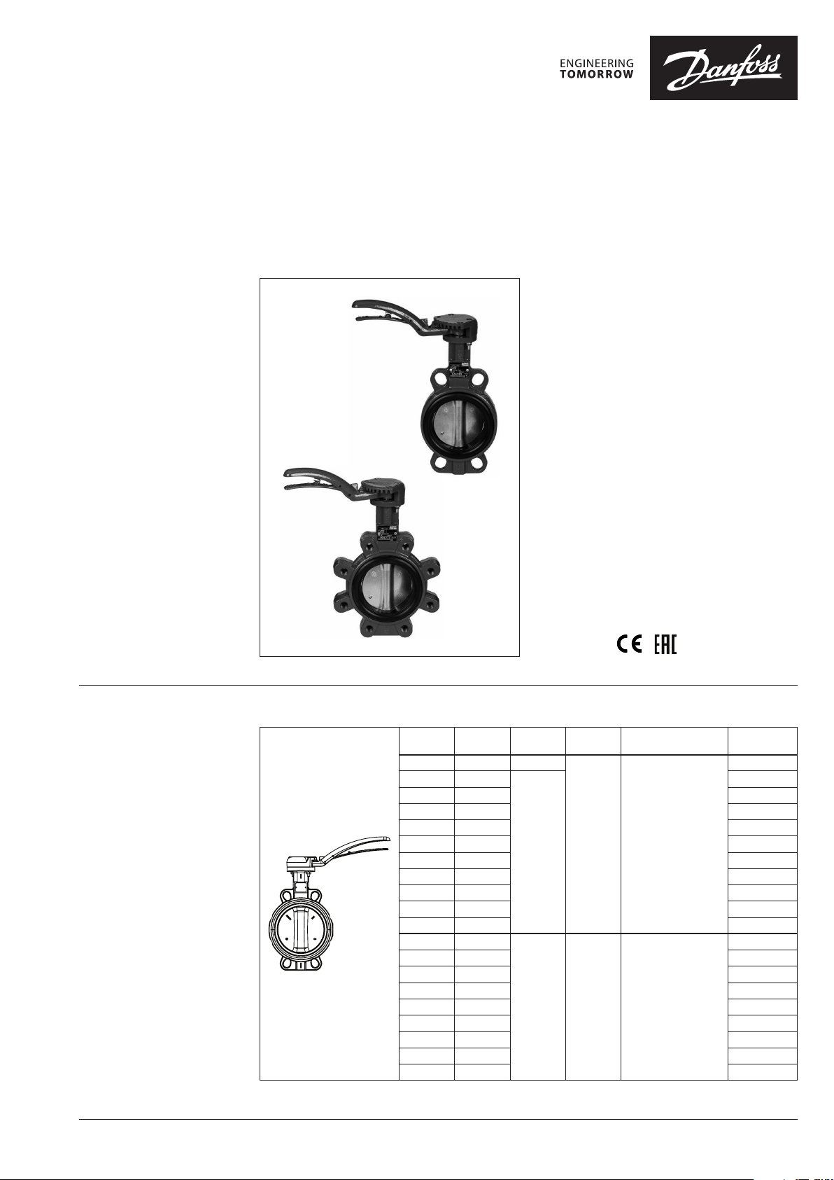
Data sheet
Butterfly valves with hand lever
VFY-WH, VFY-LH
Description Features:
• Spline driven one piece shaft connected to
spherically machined disc allows high
torque transmission i.e. quick response and
minimum back-lash
• Long term reliability due to upper and lower
anti-friction bearings
• Safe maintenance :
shaft blow out protection with circlip
• Padlockable hand lever with 10 positions.
Main Data:
• DN 25 (32)-300
• kVS 40 (62)-5635 m3/h
• PN 16 (10)
• EPDM Liner
• Stainless steel or Ductile iron Epoxy
Coated disc
• Medium:
- Circulation water, drinking water or chilled
glycolic water up to 50 %
• Medium temperature:
−10 … 120 °C (EP disc)
−10 … 130 °C (SS disc)
• Wafer or Lug connection
• Approvals:
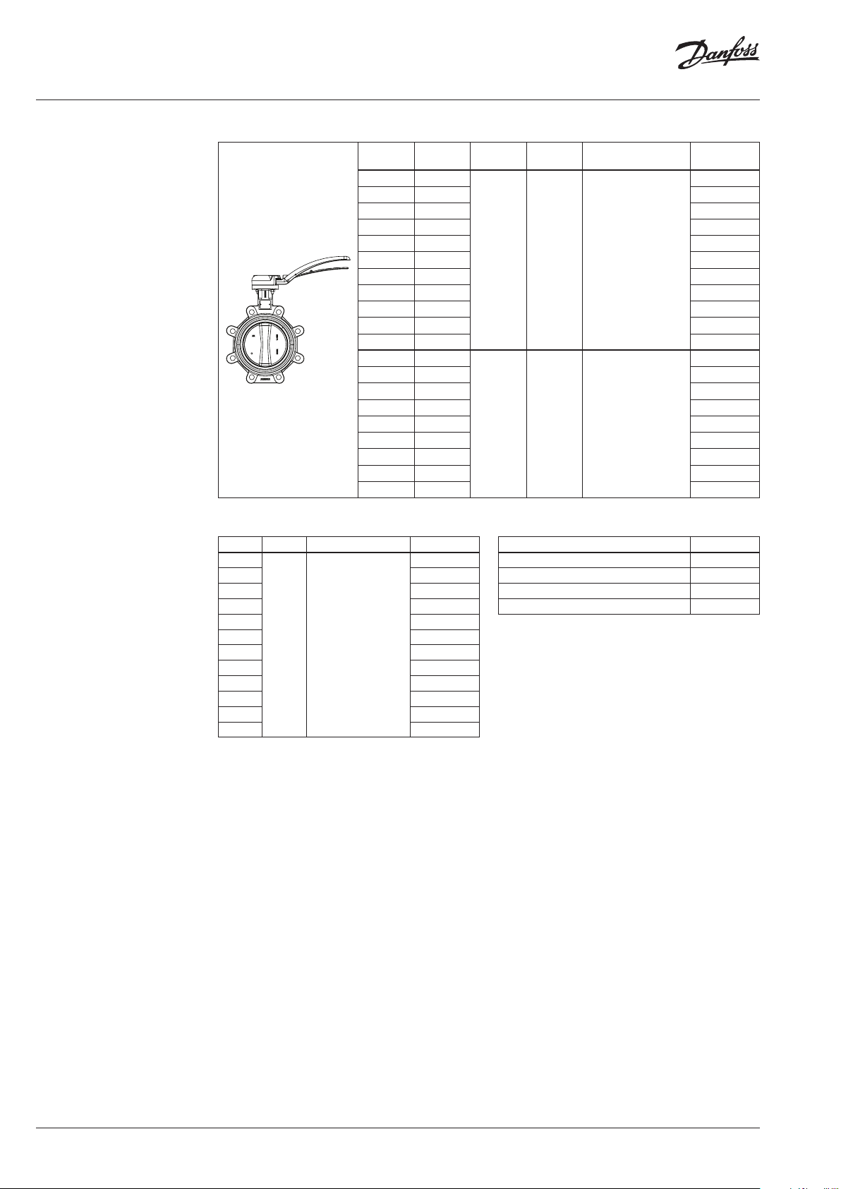
Ordering
Wafer type VFY-WH
T
k
DN
25 40 10
32/4 0 62
50 79 06 5B7410
65 174 06 5B 7411
80 275 06 5B7412
100 496 0 65B7413
125 883 0 65B7414
150 1212 065B 7415
200 2500 06 5B7416
250 3948 065B7337
300 5635 065B7338
50 79
65 174 0 65B8401
80 275 065B8402
100 496 065B8403
125 883 065B8404
150 1212 0 65B8405
200 2500 065B8406
250 3948 065B 8407
300 5635 065B8 408
VS
(m3/h)
PN
16
16 120
max
(°C)
130 Stainless Steel
Disc Code No.
Ductile iron Epoxy
Coated
065B7350
065 B7351
065B8400
© Danfoss | 2021.07 AI176286477306en-000902 | 1
Data sheet VFY-WH, VFY-LH
Ordering
Spare parts
Note:
Please contact Da nfoss sales to align on
details before ordering spare parts.
Lug type VFY-LH
DN
32 62
40 62 065B7366
50 79 065 B7420
65 174 065 B7421
80 275 065 B7422
100 496 06 5B7423
125 883 0 65B742 4
150 1212 06 5B7425
200 2500 0 65B7436
250 3948 06 5B7437
300 5635 065B7438
50 79
65 174 06 5B8 411
80 275 0 65B8 412
100 496 06 5B8413
125 883 0 65B8 414
150 1212 065B8 415
200 2500 0 65B8 416
250 3948 06 5B8 417
300 5635 06 5B8418
(m3/h)
Replacement Liner VFY-W Liner
DN PN Liner Code No.
25
32/4 0 065B7581
50 065B7582
65 065B7583
80 065B75 84
100 065B7585
125 065B7578
150 06 5B7579
200 065B7592
250 065B7593
300 065B7594
350 06 5B7591
16 EPDM
065B7580
k
VS
PN
16 130 Stainless Steel
16 120
T
(°C)
max
Disc Code No.
065B7365
065B8 410
Ductile iron Epoxy
Coated
Replacement Hand lever VFY-Handle
for DN Code No.
25/32/40/50/65/80/100 065B7605
125/150/200 065B7606
250 065B7608
300 065 B7609
2 | AI176286477306en-000902 © Danfoss | 2021.07
Data sheet VFY-WH, VFY-LH
Technical data
Typ e VF Y-WH VF Y-LH
Nominal diameter DN 25-300 32-300
kVS value
Rotation angle 90°
Leakage rate Acc. to PED 2014/68/EU, EN 12266-1, Rate A
Nominal pressure PN 16 (from DN 32-300) / 10 (for DN 25) 16
Medium Circulation water, Glycolyc water up to 50 % or drinking water
Medium temp.
Connection Wafer (centering lugs) Lug (tapped lugs)
Mounting Mounting between flanges Mounting between flanges or mounting deadline
Material
Body Cast iron EN GJL 250 (DIN GG25)
Disc Ductile iron EN GJS 400 -15 (DIN GGG 40) with Epoxy coating or Stainless Steel
Shaft Stainless steel AISI 420
Liner EPDM
Circlip Steel XC 75 / Stainless steel
O-ring Nitrile/Viton
Upper guide bush Zinc coated S. + PTFE
Lower guide bush Zinc coated S. + PTFE
Cap EN GJS-400-15/EN GJL-250
Hand lever EN GJS-400-15
1)
No visible detec table leakage during the te sting procedure
m3/h
EP disc
SS disc −10 ... 130 (see p-T diagram)
°
C
40-5635 62-5635
−10 ... 120 (see p-T diagram)
Cast iron EN GJL 250 (DIN GG25) DN 32-150
Ductile iron (DIN GGG40) DN 200-300
1)
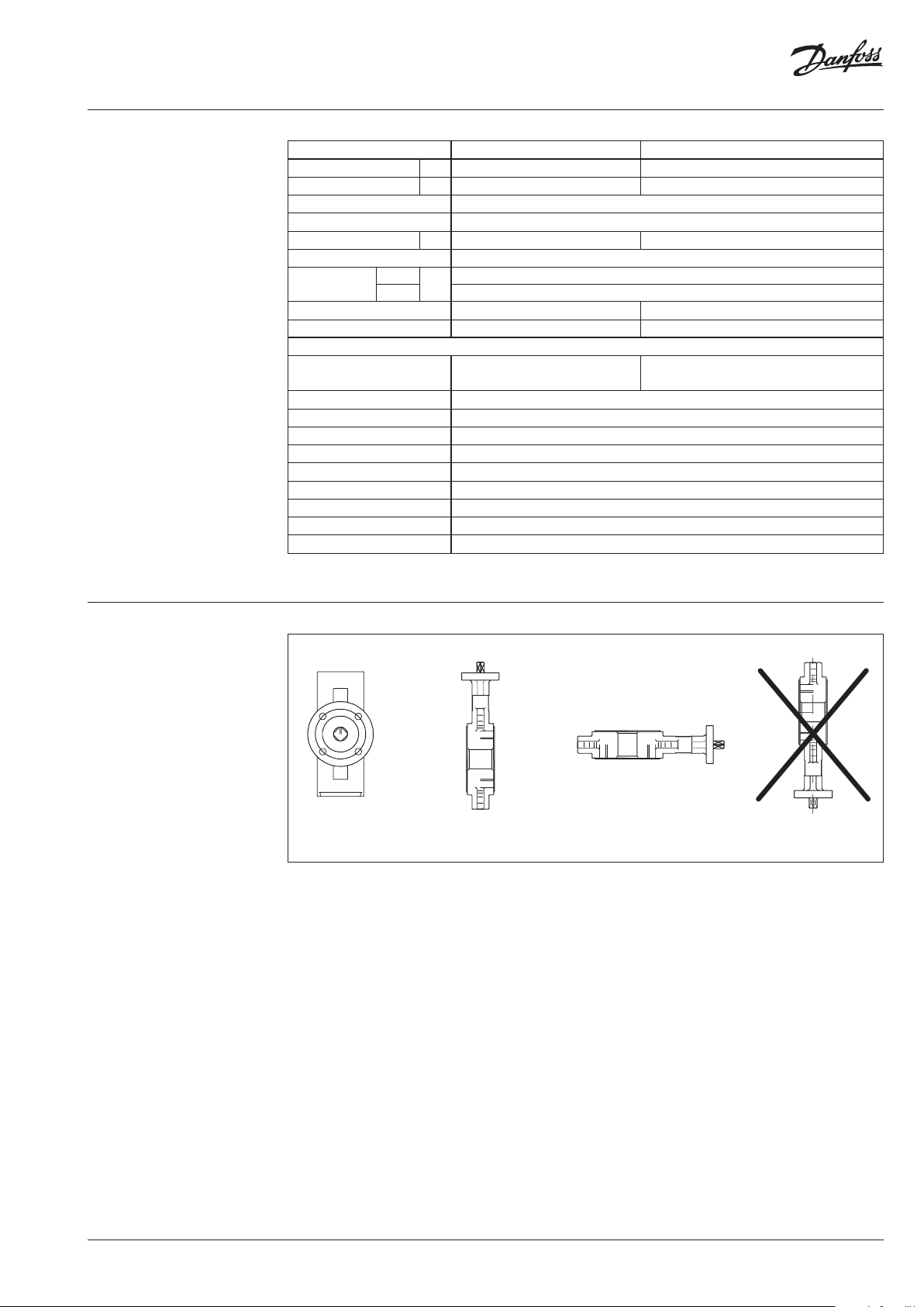
Installation positions
Not recommendedPossiblePossibleRecommended
AI176286477306en-000902 | 3© Danfoss | 2021.07

Data sheet VFY-WH, VFY-LH
10
15
20
25
30
1 DN
1 DN
1 DN
Installation conditions
It is recommended that distances indicated
below are respected in order to prolong lifetime
of the valve. Mounting the valve close to
pipework junctions (turbulent zones) increases
wear.
5-6 DN
DN
5-6 DN
DN
2-3 DN
DN
P-T diagram
2-3 DN
DN
DN
Pressure (bar)
5
0
10 -10 0
DN 32-30 0
DN 25
30 50 70 90 100 110 120 130
Temperature (°C)
DN
1 DN
4 | AI176286477306en-000902 © Danfoss | 2021.07

Data sheet VFY-WH, VFY-LH
∆P
2777,8
1111,1
1666,7
2222,2
1388,9
FLOW Pressure drop kPa (100 kPa = 1bar = ~ 10m H2O)
Headloss diagram
For water at 20°C
2,8
5,6
8,3
11,1
10020 30 401072345 60 8015681,5
10
20
30
40
DN
25
111,1
138,9
166,7
222,2
277,8
417,7
555,6
694,4
833,3
l/sec m3/h
Flow Rate
(liquid with specic a gravity of 1)
16,7
22,2
27,7
41,7
55,6
69,4
83,3
60
80
100
150
200
250
300
400
500
600
800
1000
1500
2000
2500
3000
4000
5000
6000
8000
10000
32-40
50
65
80
100
125
150
200
250
300
AI176286477306en-000902 | 5© Danfoss | 2021.07

Data sheet VFY-WH, VFY-LH
Design
1. Body
2. Disc
3. Shaft
4. Liner
5. Circlip
6. O-ring
7. Upper guide bush
8. Lower guide bush
9. Cap
10. Hand lever
10
9
5
6
7
3
2
4
1
8
6 | AI176286477306en-000902 © Danfoss | 2021.07

Data sheet VFY-WH, VFY-LH
A B E
C
D
A B E
C
D
Dimensions
VF Y-WH
Ø
VF Y-LH
C
DN
32/4 0 43 57 163 200 33 45 2.4
100 100 106 208 200 52 45 6.3
125 12 5 12 0 223 290 56 65 7.5
150 150 131 236 290 56 65 8.5
200 200 16 5 258 290 60 65 12 .2
250 250 19 6 266 450 68 46 23.7
300 300 238 336 450 79 86 28. 2
Ø A B C D E Weight (kg)
mm WFY-WH
25 32 50 15 8 200 33 45 2.3
50 54 62 169 200 43 45 3.3
65 70 70 178 200 46 45 3.6
80 85 89 184 200 46 45 4.0
EBA
DN
Ø
D
32/4 0 43 57 163 200 33 45 2.8
DN
Ø
100 100 106 208 290 52 65 7. 6
125 12 5 12 0 223 290 56 65 10.0
150 150 131 236 290 56 65 11. 0
200 200 162 290 290 60 98 17. 2
C
Ø A B C D E Weight (kg)
mm WFY-LH
50 54 62 169 200 43 45 3.7
65 70 70 178 200 46 45 4.1
Ø A B C D E Weight (kg)
mm WFY-LH
80 85 89 184 200 46 45 5.1
EBA
Ø
D
DN
250 250 19 8 266 450 68 46 29. 8
300 300 227 290 450 77 46 37. 6
Ø A B C D E Weight (kg)
mm WFY-LH
AI176286477306en-000902 | 7© Danfoss | 2021.07

Data sheet VFY-WH, VFY-LH
© Danfoss | DCS-S/SI | 2021.078 | AI176286477306en-000902
 Loading...