

Page 1
Data sheet
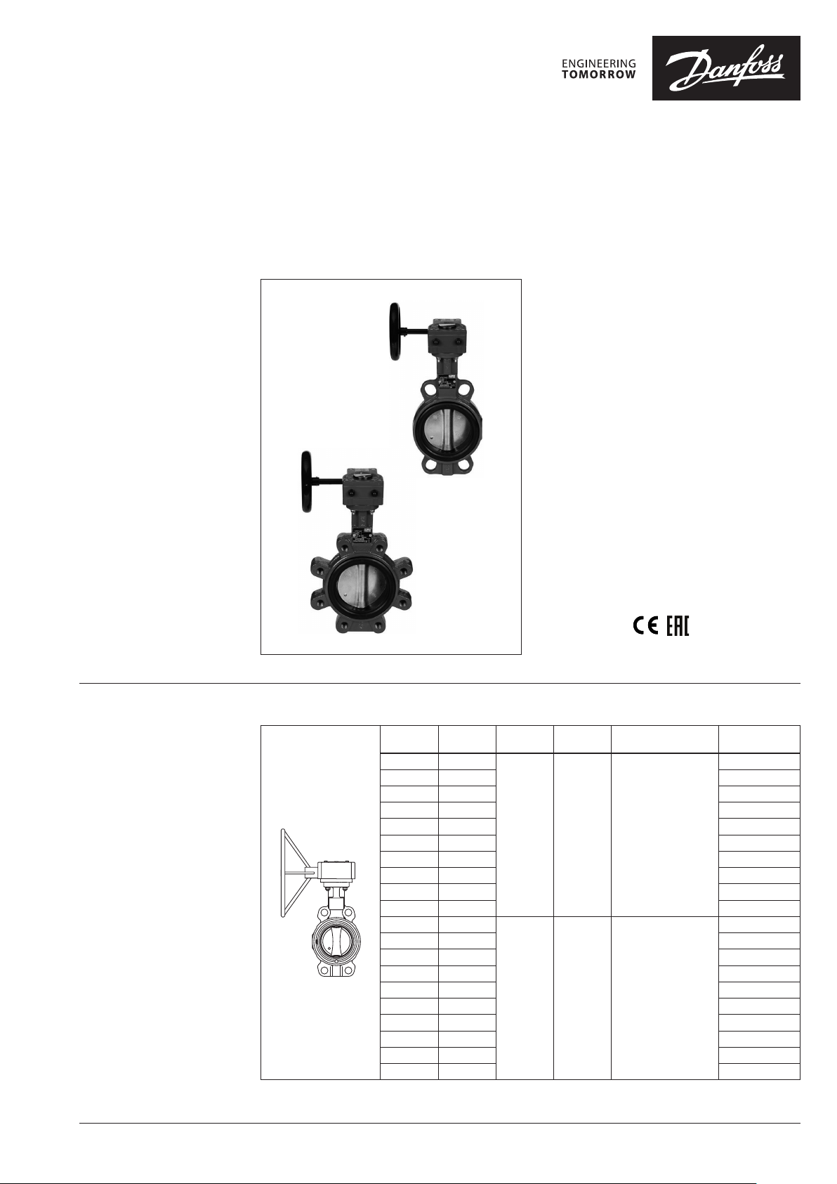
Butterfly valves with gear box
VFY-WG, VFY-LG
Description
Features:
• Spline driven one piece shaft connected to
spherically machined disc allows high torque
transmission i.e. quick response and minimum
back-lash
• Long term reliability due to upper and lower
anti-friction bearings
• Safe maintenance: shaft blow out protection
with circlip
• Position indicator
Main Data:
• DN 50-350
• kVS 79-8520 m3/h
• PN 16
• EPDM Liner
• Stainless steel or Ductile iron Epoxy
Coated disc
• Medium:
- Circulation water, drinking water or chilled
glycolic water up to 50 %
• Medium Temperature:
−10 … 120 °C (EP disc)
−10 … 130 °C (SS disc)
• Wafer or Lug connection
• Approvals:
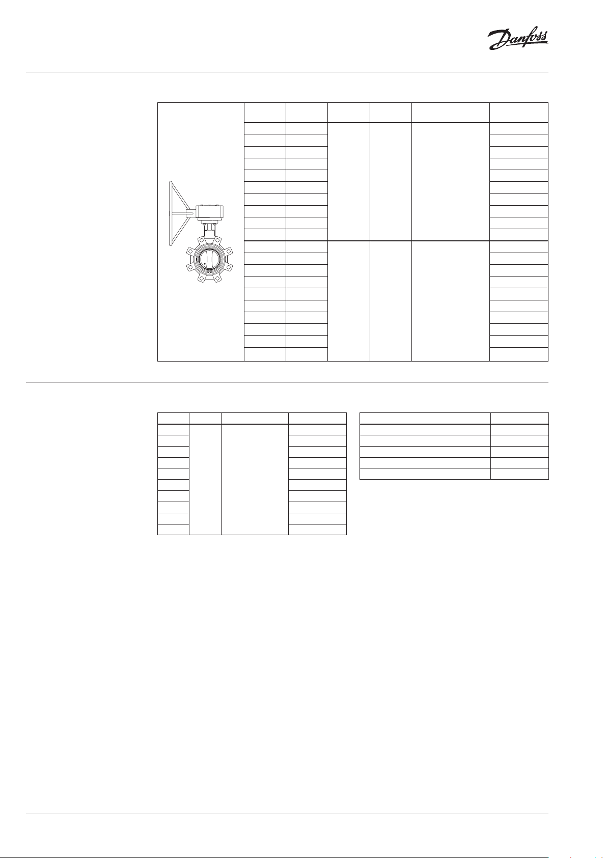
Ordering
Wafer type VFY-WG
XX
X
k
DN
50 79
65 174 06 5B7441
80 275 06 5B744 2
100 496 0 65B74 43
125 883 065B7444
150 1212 065B744 5
200 2500 06 5B744 6
250 3948 0 65B74 57
300 5635 0 65B74 58
350 8520 065B7449
50 79
65 174 065B 8421
80 275 065B8422
100 496 065B8423
125 883 065B8424
150 1212 065B8425
200 2500 065B8426
250 3948 065B8427
300 5635 065B8 428
350 8520 065B8429
VS
(m3/h)
PN
16 130 Stainless Steel
16 120
T
(°C)
max
Disc Code No.
06 5B744 0
065B8420
Ductile iron Epoxy
Coated
© Danfoss | 2020.11 AI176286477249en-010903 | 1
Page 2
Data sheet VFY-WG, VFY-LG
Ordering
Lug type VFY-LG
DN XX
XX XX
XX
XX
DN
(m3/h)
50 79
k
VS
PN
T
(°C)
max
Disc Code No.
06 5B746 0
65 174 06 5B7461
80 275 065B7462
100 496 0 65B74 63
125 883 0 65B74 64
150 1212 065B7465
16 130 Stainless Steel
200 2500 065B7406
250 3948 065B7407
300 5635 0 65B74 08
350 8520 065B7469
50 79
065B8430
65 174 065B 8431
80 275 065B8432
100 496 065B8433
125 883 065B8434
150 1212 065B8435
16 120
Ductile iron Epoxy
Coated
200 2500 065B8436
250 3948 065B 8437
300 5635 065B8438
350 8520 065B8439
Spare parts
Replacement Liner VFY-W Liner
DN PN Liner Code No.
50
65 065B7583
80 065B7584
100 065B7585
125 065B7578
150 06 5B7579
16 EPDM
200 065B7592
250 065B7593
300 065B7594
350 06 5B7591
065B7582
Replacement gearbox VFY-G earbox
for DN Code No.
50/65/80/100 065B7595
125/150/200 065B7596
250 065B7598
300 065B7599
350 065 B7600
2 | AI176286477249en-010903 © Danfoss | 2020.11
Page 3
Data sheet VFY-WG, VFY-LG
mounting between flanges
mounting deadline
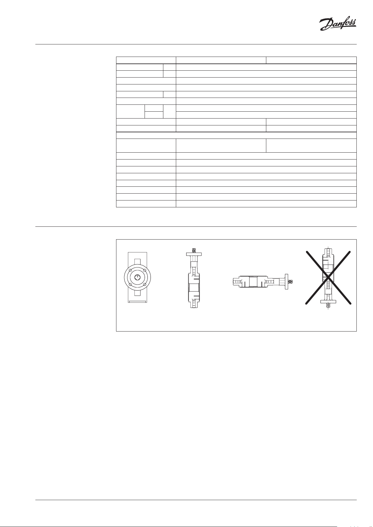
Technical data
Typ e VF Y-WG VFY- LG
Nominal diameter DN 50-350
kVS value m3/h 79-8520
Rotation angle 90 °
Leakage rate Acc. to PED 2014/68/EU, EN 12266-1, Rate A
Nominal pressure PN 16
Medium Circulation water, Glycolyc water up to 50 % or drinking water
Medium
temperature
Connection Wafer (centering lugs) Lug (Tapped lugs)
Mounting
Material
Body
Disc Ductile iron EN GJS 400 -15 (DIN GGG 40) with Epox y coating or Stainless Steel
Shaft Stainless steel AISI 420
Liner EPDM
Circlip Steel XC 75 / Stainless steel
O-ring Nitrile/Viton
Upper guide bush Zinc coated S. + PTFE
Lower guide bush Zinc coated S. + PTFE
Gear box Aluminium
1)
No visible detec table leakage during the te sting procedure
EP disc
SS disc −10 ... 130 (see p-T diagram)
°
C
Cast iron EN GJL 250 (DIN GG25) DN 50 -300 Cast iron EN GJL 250 (DIN GG25) DN 50 -150
Ductile iron (DIN GGG40) DN 350 Ductile iron (DIN GGG40) DN 200-350
−10 ... 120 (see p-T diagram)
1)
Installation positions
Not recommendedPossiblePossibleRecommended
AI176286477249en-010903 | 3© Danfoss | 2020.11
Page 4

Data sheet VFY-WG, VFY-LG
1 DN
1 DN
1 DN
10
15
20
25
30
Installation conditions
It is recommended that distances indicated
below are respected in order to prolong lifetime
of the valve. Mounting the valve close to
pipework junctions (turbulent zones) increases
wear.
5-6 DN
DN
5-6 DN
DN
2-3 DN
DN
P-T diagram
2-3 DN
DN
DN
Pressure (bar)
5
0
30 50 70 90 100 110 120 130
10 -10 0
Temperature (°C)
DN
1 DN
4 | AI176286477249en-010903 © Danfoss | 2020.11
Page 5

Data sheet VFY-WG, VFY-LG
∆PP
0
2777,8
1111,1
1666,7
2222,2
1388,9
FLOW Pressure drop kPa (100 kPa = 1 bar = ~ 10m HFLOW Pressure drop kPa (100 kPa = 1 bar = ~ 10m H
2
O)O)
Headloss diagram
For water at 20 °C
2,8
5,6
8,3
11,1
16,7
22,2
27,7
41,7
55,6
69,4
83,3
111,1
138,9
166,7
222,2
277,8
417,7
555,6
694,4
833,3
10
20
30
40
60
80
100
150
200
250
300
400
500
600
800
1000
1500
2000
2500
3000
4000
5000
6000
8000
10000
2
10020 30 401072345 60 8015681,5
∆
DN
50
65
80
10
125
150
200
250
300
350
l/sec m3/h
Flow Rate
(liquid with specific a gravity of 1)
AI176286477249en-010903 | 5© Danfoss | 2020.11
Page 6

Data sheet VFY-WG, VFY-LG
Design
1. Body
2. Disc
3. Shaft
4. Liner
5. Circlip
6. O-ring
7. Upper guide bush
8. Lower guide bush
9. Gear box
9
5
6
7
3
2
4
8
1
6 | AI176286477249en-010903 © Danfoss | 2020.11
Page 7

Data sheet VFY-WG, VFY-LG
C
B
A
Ø E
A B
C
Dimensions
Ø
XX
X
D
C
Waffer type VFY-WG
Ø A B C D ØE
DN
50 54 62 225.5 120 43 125 3.6
65 70 70 234.5 120 46 12 5 4
80 85 89 240.5 120 46 125 4.3
100 100 106 264.5 120 52 12 5 6.3
125 12 5 120 279.5 120 56 125 7.4
150 150 131 292.5 120 56 12 5 8.5
200 200 166 315 120 60 12 5 12. 3
250 250 196 429 239 70 250 25.2
300 300 238 453 239 77 250 28.9
350 340 270 468 239 78 250 41.4
mm
Weight
(kg)
ØE
B
Ø
Lug type VFY-LG
Ø A B C D ØE
DN
50 54 62 225.5 120 43 125 4
65 70 70 234.5 120 46 12 5 4.5
mm
Weight
(kg)
A
D
Ø E
Lug type VFY-LG
Ø A B C D ØE
DN
DN XX
XX XX
Ø
XX
XX
80 85 89 240.5 120 46 125 5.4
100 100 103 264.5 120 52 125 7. 9
125 12 5 119 279.5 12 0 56 125 9.9
150 150 133 292. 5 120 56 12 5 11 .9
mm
D
ØEC
Weight
(kg)
Lug type VFY-LG
Ø A B C D ØE
BA
Ø
D
DN
200 200 162 315 120 60 125 17
250 250 198 429 239 68 250 30.8
300 300 227 453 239 77 250 38.3
350 340 24 8 468 239 78 250 49.7
mm
AI176286477249en-010903 | 7© Danfoss | 2020.11
Weight
(kg)
Page 8

Data sheet VFY-WG, VFY-LG
© Danfoss | DHS-SMDBT/SI | 2020.118 | AI176286477249en-010903
 Loading...