

Page 1
Data sheet
Seated valve (PN 16 & PN 25)
VFM 2 – Two way valve, flange
Description
Ordering
Features:
• Low seat leakage rate (< 0,03 % of k
• Rangeability R=
)
vs
>100:1 by PN 16
>100:1 by PN 25 up till DN 125 otherwise >80:1
• Pressure relieved design
Main data:
• DN 65-250
• kvs 63-900 m3/h
• PN 16 & PN 25
• Linear characteristic by 0-30% valve stroke
and Logarithmic characteristic by 30-100%
valve stroke.
• Stem down to close
• Medium:
Circulation water / glycolic water up to 50%
Valve for heating, district heating and district
cooling systems.
VFM 2 valve can be used together with following
Danfoss actuators:
• AMV(E) 655
• AMV(E) 658 SU/SD
• AME 659 SD
• Temperature:
2 (−10*) … 150 °C
* At temperature s from −10 °C up to +2 °C use stem hea ter
• Flange PN 16 & 25 connections
• Push-pull connection between valve and
actuator
• Compliance with Pressure Equipment
Directive 2014/68/EU
• AMV(E) 85/86 (for VFM 2 DN 150-250)
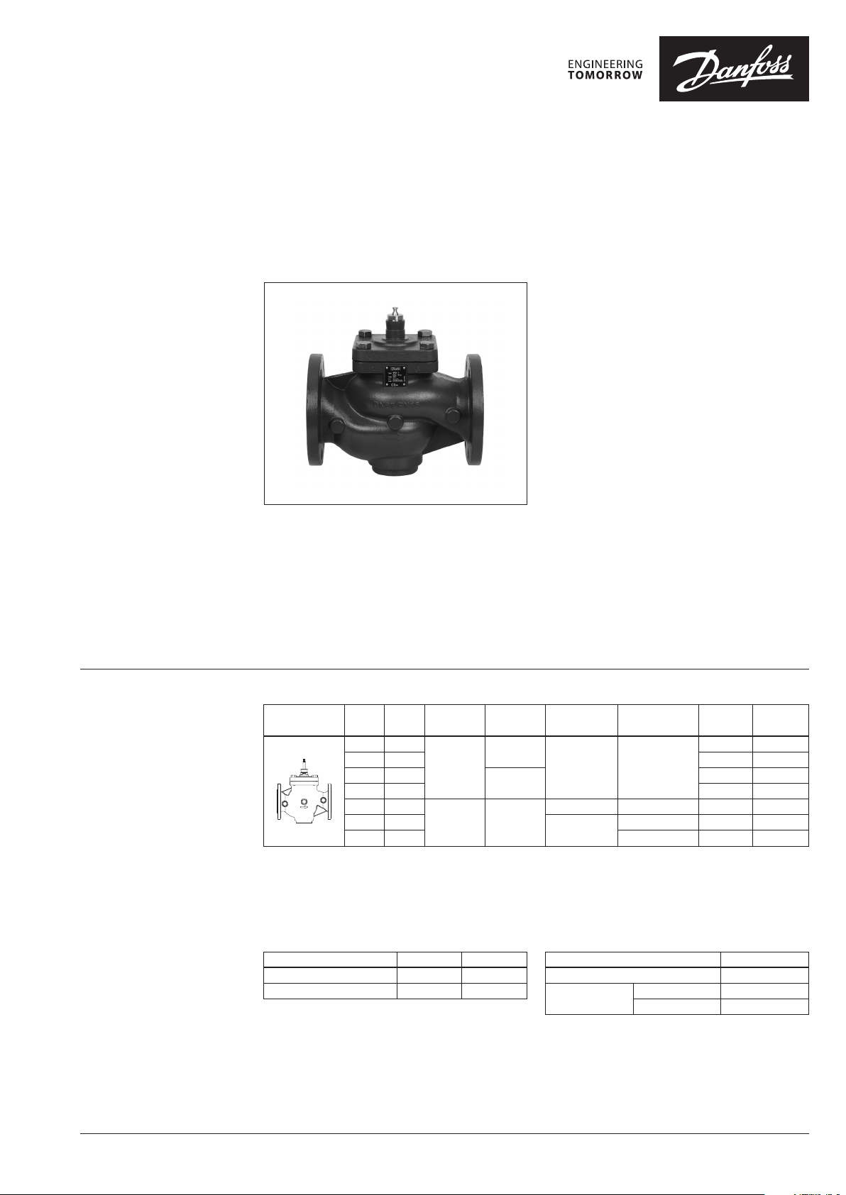
Valve VFM 2
Picture DN
200* 630
1)
Δp
is maximum p ermissible differen tial pressure across the valve ref fered for the whole ac tuating range of motorised val ve
max.
(a function of a ctuator's perfo rmance)
2)
Δps is maximum p ermissible clossing dif ferential pressure appl ied in fully closed positi on of the valve, at which valve will se al tightly
(close off pressure)
* For DN 200 in comb ination with AMV(E)85/86: kvs is reduced by 15%
For DN 250 in combinat ion with AMV(E)85/86: kvs is reduced by 20%
250* 900 5 065B3506 065B3087
kVSPN 16 Δp
(m3/h) (bar) (bar) for AMV(E)65x for AMV(E)85/86
65 63
80 100 065B3501 065B3082
100 160
125 250 065B3503 065B3084
150 400
2)
PN 25 Δp
S
16
10 10
2)
Δp
S
20
16
(bar) 1)Δp
max.
8 -
4 10 065B3504 065B3085
3
1)
(bar)
max.
7 065B3505 065B3086
PN 16
Code No.
065B3500 065B3081
065B3502 065B3083
PN 25
Code No.
Accessories
Typ e DN Code No.
Stem heater for AMV(E) 85/86 150-250 0 65Z7021
Stem heater for AMV(E) 65X 65-2 50 0 65Z7022
Service kits
Typ e Code No.
Top cover sealing set VFM 2 065B3528
Stuffing box
DN 65-12 5 065B3529
DN 150-250 065B3530
© Danfoss | 2021.11 AI148986474384en-010602 | 1
Page 2
Data sheet Two way valve VFM 2
Technical data
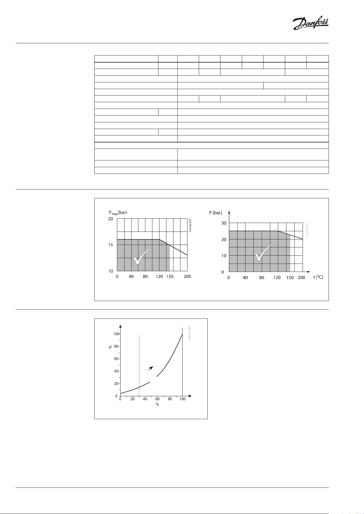
Pressure temperature
diagram
Nominal diameter DN 65 80 100 125 150 200 250
k
value m3/h 63 10 0 160 250 400 630 900
VS
Stroke mm 30 34 40 50
Rangeability PN 16 >10 0:1
Rangeability PN 25 >10 0:1 >80:1
Control characteristic Lin by 0-30% and Log characteristic by 30-100% valve stroke
Cavitation factor z PN16 & PN 25 0.45 0.40 0.35 0.25 0.21
Leakage acc. to standard IEC 534 < 0.03 % of kVS
Nominal pressure PN 16 & 25
Medium Circulation water / glycolic water up to 50 % (standard VDI 2035)
Medium pH Min. 7, Max. 10
Medium temperature
Connections Flange PN 16 & 25 acc. to EN 1092-2
Materials
Valve body and cover
Valve seat, cone and spindle Stainless steel
Stuffing box sealing EPDM
1)
At tem peratures from –10 °C up to +2 °C use stem heater
EN-GJL-250 (GG-25)
o
C 2 (–10 1) ) … 150
Grey cast iron EN-GJL-250 (GG-25) for PN 16
Ductile iron EN-GJS-400-18 for PN 25
EN-GJS-400-18
PN 25
PN 16
Valve characteristics
Maximum allowed operating pressure as a function of medium temperature (according to EN 1092-2)
lin log
(30%) (70%)
Capacity
AB
A
Stroke
Stroke
Lin by 0-30% and Log by 30 -100% valve stroke
2 | AI148986474384en-010602 © Danfoss | 2021.11
Page 3

Data sheet Two way valve VFM 2
Installation Hydraulic connections
Mount according to flow direction as indicated
on valve body.
Valve mounting
Before mounting the valve be sure that the pipes
are clean and free from swarf. It is essential that
the pipes are lined up squarely with the valve
at each connection and that they are free from
vibrations.
Install the motorized control valves with the
actuator in allowed position as described below.
<
Leave sufficient clearance to facilitate the
dismantling of the actuator from the valve body
for maintenance purposes.
Note that the actuator may be rotated up to 360°
with respect to the valve body by loosening the
retaining fixture. After this operation re-tighten.
Note:
Install a strainer upstream of the valve
(e.g. Danfoss FVR/FVF)
AMV(E)
FVR/FVF
<
<
<
Design
1. Valve body
2. Valve cover
3. Stuffing box
4. Valve stem
5.
Valve cone (pressure relieved)
6. Valve seat
VFM 2 DN 65 - 250 + AMV(E) 65x VFM 2 DN 150 - 250 + AMV(E) 85 / 86
AI148986474384en-010602 | 3© Danfoss | 2021.11
Page 4

Data sheet Two way valve VFM 2
2p1p
1p
a authority, Valve
∆+∆
∆
=
5.0
p2
p
a
1
1
62.0
557.90
7.90
authority valve hence
50.39
5536
36
authority valve hence
Sizing
Flow Rate (liquid with specific a gravity of 1)
l/sec m3/h
max
Δp
kVS 900
kVS 630
kVS 400
kVS 250
kVS 160
kVS 100
kVS 63
FLOW Pressure drop kPa (100 kPa = 1bar = ~ 10 m H2O)
Example
Design data:
Flow rate: 60 m3/h
System pressure drop: 55 kPa
Locate the horizontal line representing a flow
rate of 60 m3/h (line A-A). The valve authority is
given by the equation:
Where:
Δp1 = pressure drop across the fully open
valve
Δp2 = pressure drop across the rest of the
circuit with a full open valve
The ideal valve would give a pressure drop equal to
the system pressure drop (i.e. an authority of 0,5)
if: Δp1 = Δp2
In this example an authority of 0,5 would be
given by a valve having a pressure drop of
55 kPa at that flow rate (point B). The intersection
of line A–A with a vertical line drawn from B lies
between two diagonal lines; this means that no
ideally-sized valve is available.
The intersection of line A–A with the diagonal
lines gives the pressure drops stated by real, rather
than ideal, valves. In this case, a valve with kVS 63
would give a pressure drop of 90,7 kPa (point C):
The second largest valve, with kVS 100, would
give a pressure drop of 36 kPa (point D):
4 | AI148986474384en-010602 © Danfoss | 2021.11
Page 5

Data sheet Two way valve VFM 2
Dimensions
15°
30°
22.5°
45°
45°
H
k
n
d
2
L
1
H
k
1
H
d
2
L
1
n
H
k
1
H
d
L
VFM 2 DN 65
n
1
H
2
1
VFM 2 DN 80-150
VFM 2 DN 200, 250
Mi n. 150
2
H
Mi n. 150
3
H
1
H
L
L
AMV(E) 65x + VFM 2 (DN 65-250) AMV(E) 85/86 + VFM 2 (DN 150-250)
PN 16 PN 25 PN 16 & PN 25
Typ e DN
L L1H k d
mm mm mm
2
Weight
n
L L1H k d
(kg)
2
Weight
n
(kg)
65 290 185 336 145 19 4 25 290 185 336 145 19 8 23.5 114
80 310 200 336 160 19 8 33 310 20 0 336 160 19 8 27 114
100 350 242 414 18 0 19 8 48 350 242 414 19 0 23 8 46 148
VFM 2
125 400 250 416 210 19 8 57 400 270 416 220 28 8 56 149
150 480 310 516 240 22 8 101 480 320 516 250 28 8 102
200 600 385 669 295 23 12 208 600 385 669 310 28 12 197 245 686 685
250 730 500 728 355 26 12 348 730 500 728 370 31 12 334 267 732 732
AI148986474384en-010602 | 5© Danfoss | 2021.11
1
H
H1H2H
493.5
494.5
528.5
529.5
182. 5
628.5
3
-
-
-
-
639
Page 6

Data sheet Two way valve VFM 2
© Danfoss | DCS-SGDPT/SI | 2021.116 | AI148986474384en-010602
 Loading...