

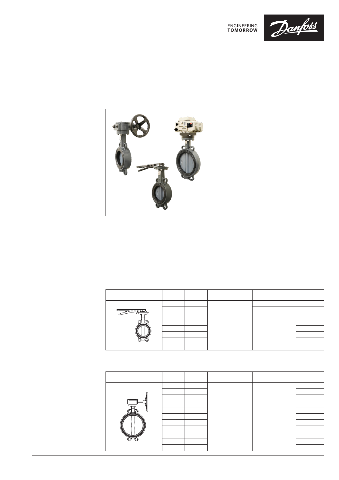
Data sheet
Wafer type Butterfly valves
VFH2 DN 32-600
Description
Features:
• Long term reliability due to upper and lower
anti-friction bearings
• No leakage in both direction in shut of
position
• Safe maintenance: shaft blow out protection
with circlip
• Padlockable hand lever with 10 positions
• Position indicator in Gear box or actuator
• Complete installation from factory - ready for
installation
• Unique internal moisture removal
• Debugging with power on
• Actuator action selectable when input signal
missing
• Input signal voltage/current selectable by
internal DIP switch
Main Data:
• DN32-600
• kVS 63-36946 m3/h
• PN16
• Maximum differential pressure:
- 16 bar (Manual)
- 10 bar (Motorized)
• Leakage rate A
• EPDM Liner
• Nylon coated disc
• Medium: -10 ... 95°C
Circulation water, drinking water or chilled
glycolic water up to 50 %
• Ambient temperature (motorized versions):
−30 … 60 °C
• Duty rating IEC34: cycle S4 (50 % )
• Power supply: 220 ± 10% V AC 50/60Hz
• Wafer type
Ordering
Handle VFH2 -WH
Picture DN
32 63
40 72
50 82 003Z2400
65 207 0 03Z2401
80 288 003Z2402
100 569 003Z2403
125 8 74 003Z2404
1)
4pcs round ing order qty (4pcs industri al pack)
2)
2pcs roundin g order qty (2pcs industria l pack)
150 134 8 003Z2405
Worm Gear VFH2 -WG
Picture DN
100 569
125 8 74 003Z2407
150 134 8 003Z2408
200 2692 003Z240 9
250 5550 0 03Z2 410
300 7557 00 3Z 2411
350 10212 00 3Z2412
400 14042 003Z 2413
450 18 600 00 3Z2414
500 23915 0 03Z2 415
600 36946 0 03Z2 416
k
VS
(m3/h)
k
VS
(m3/h)
T
PN
16 95
PN
16 95 Nylon Coating
(°C)
T
(°C)
max
max
Disc Code No.
Stainless Steel 003Z2398
Nylon coating
Disc Code No.
003Z2399
003Z2406
1)
2)
2)
2)
2)
2)
2)
2)
© Danfoss | 2021.05 AI361151079342en-010301 | 1
Data sheet Danfoss Butterfly valve VFH2
Ordering (continuous)
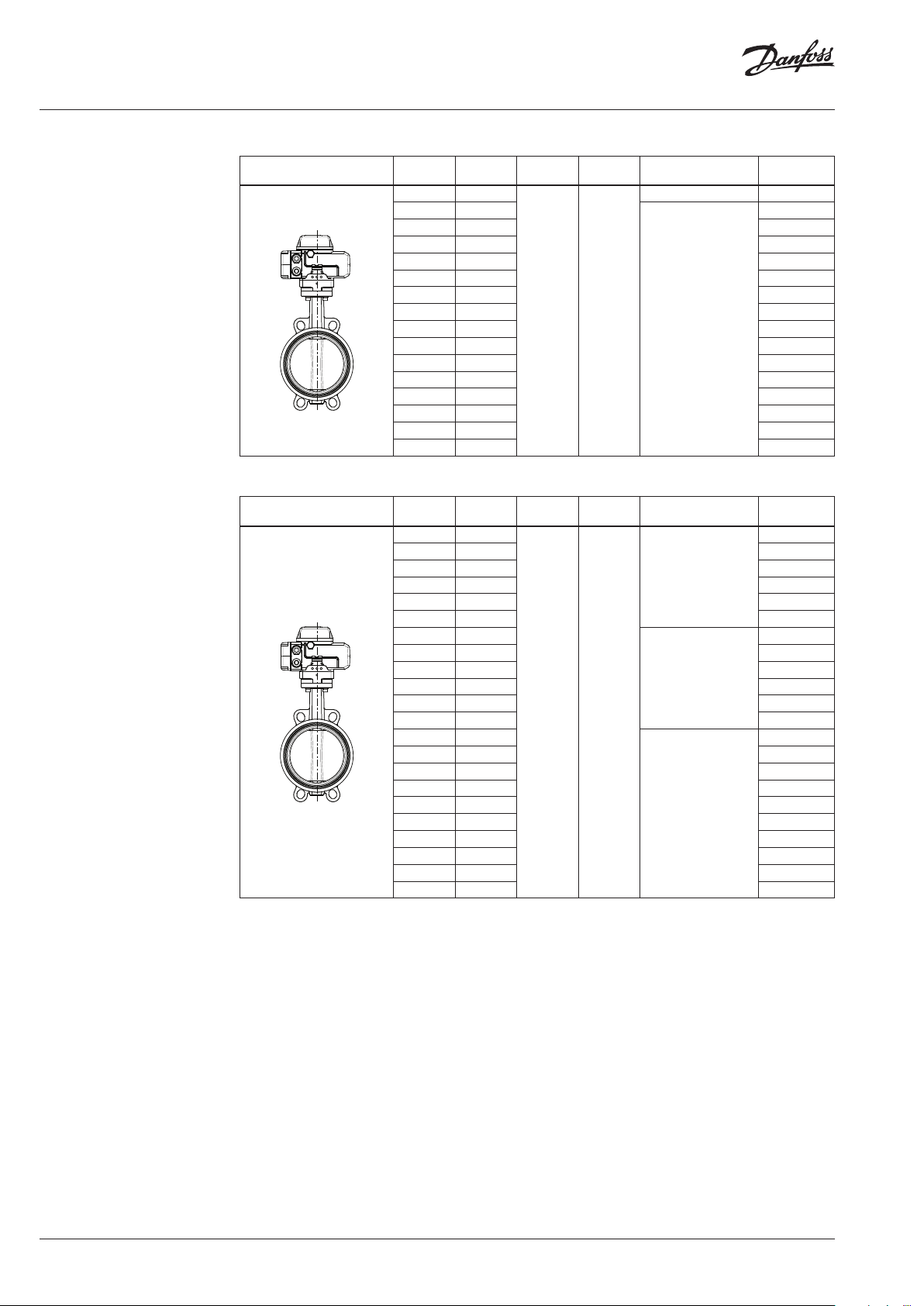
Motorized On/off VFH2 -WAO
Picture DN
Modulating VFH2 -WAM
Picture DN
Note: Same disk mate rial as WAO versions
k
(m3/h)
32 63
40 72
VS
PN
T
(°C)
max
Disc Code No.
Stainless Steel 003Z2360
003Z2363
50 82 003Z2366
65 207 003Z2369
80 288 003Z2372
100 569 003Z2375
125 8 74 003Z2378
150 134 8 003Z2380
200 2692 003Z2382
16 95
Nylon coating
250 5550 003Z2384
300 7557 003Z2386
350 10212 0 03Z2388
400 14042 003Z2390
450 18 600 003Z2392
500 23915 003Z2394
600 36946 003Z2396
(m3/h)
32 63
k
VS
PN
T
(°C)
max
Input signal Code No.
003Z2 361
40 72 003Z2364
50 82 003 Z2367
65 207 003Z2370
2 ~ 10 V
80 288 003Z2373
100 569 00 3Z2376
32 63
003Z2362
40 72 003Z2365
50 82 003Z2368
65 207 003Z2371
80 288 003Z 2374
100 569 003Z2377
16 95
125 8 74
4 ~ 20 mA
003Z2379
150 134 8 003Z2381
200 2692 003Z2383
250 5550 003Z2385
300 7557 003Z2387
350 10212 003Z2389
2 ~ 10 V / 4 ~20 mA
400 14042 003Z2391
450 18 600 003Z2393
500 23915 003Z2395
600 36946 003Z2397
2 | AI361151079342en-010301 © Danfoss | 2021.05
Data sheet Danfoss Butterfly valve VFH2
m3/h
P r
Technical data
Valve
Nominal diameter DN 32 40 50 65 80 100 125 15 0 200 250 300 350 400 450 500 600
k
value m3/h 63 72 82 207 288 569 874 134 8 2692 5550 7557 10212 140 42 18600 23915 36946
VS
Torque 16Bar Nm 15 23 29 46 68 95 18 0 235 320 800 1158 16 00 1762 3790
Torque 10Bar Nm 10 15 26 35 55 73 115 165 265 420 650 1035 1200 180 0
Rotation angle 90 °
Leakage rate Acc. to PED 2014/68/EU, EN 12266-1, Class A
Nominal pressure PN 16
Medium Circulation water, drinking water, chilled glycolic water up to 50%
Medium
temperature
Connection Centering lugs (Wafer type)
Mounting Mounting between f langes (ISO 7005.2)
Material Mounting between flanges
On/off actuator
Valve b ody DN 32 40 50 65 80 100 125 150 200 250 300 350 400 450 500 600
Opening time s 22 27 33 30 45 31 48 75
Torque Nm 50 100 200 400 600 1000 160 0 2500
Power supply 220 ± 10% V AC
Frequency (AC) 50/60 Hz
Power W 10 25 45 90 140
Signal On⁄ Of f
Ambient temperature −30 … 60 °C
Duty Rating IEC34 S2
Grade of enclosure IP 67
Humidity conditions up to 95% (IEC 60730.1)
Modulating actuator
Valve b ody DN 32 40 50 65 80 100 125 150 200 250 300 350 400 450 500 600
Opening time s 22 27 33 30 45 31 48 75
Torque Nm 50 100 200 400 600 1000 160 0 2500
Power supply 220 ± 10% V AC
Frequency (AC) 50/60 Hz
Power W 10 25 45 90 140
Input signal
Output signal 4 - 20 mA
Ambient temperature −30 … 60 °C
Duty Rating IEC34 S4 [50 %]
Grade of enclosure IP 67
°C −10 … 95
2 - 10 V or/and 4 - 20 mA
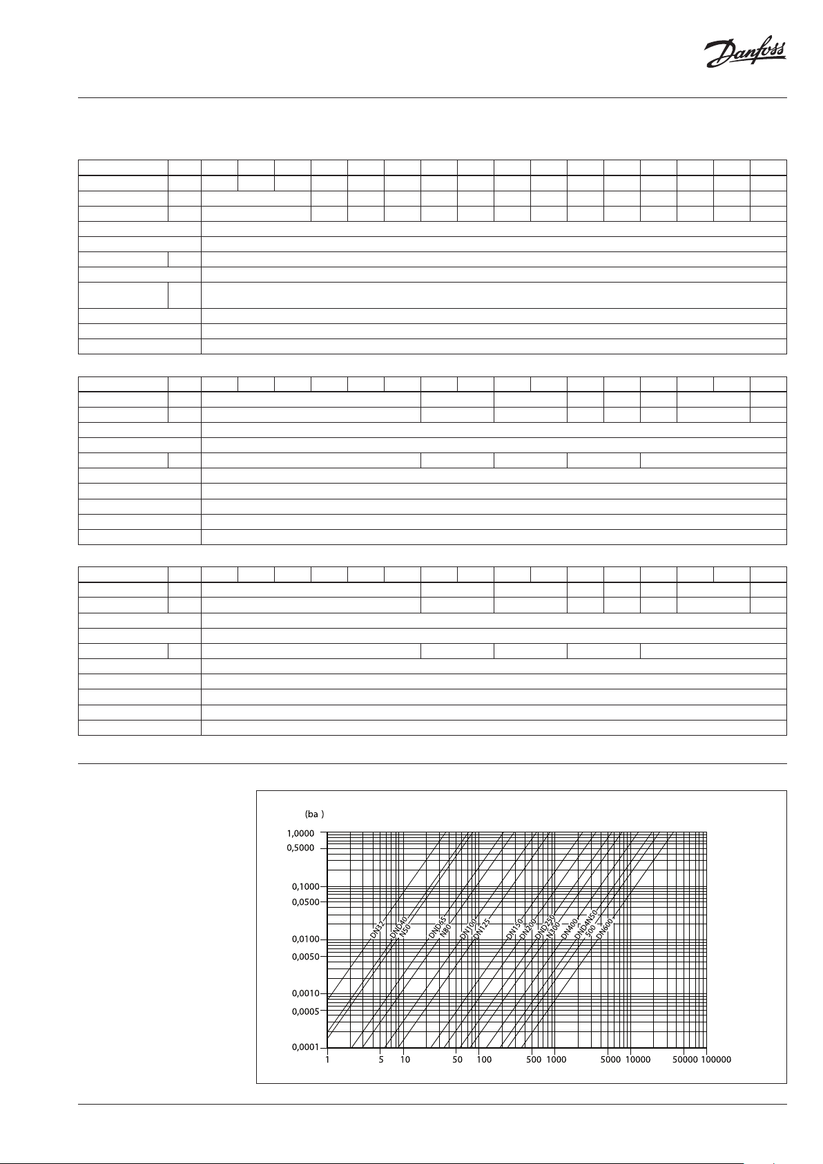
Headloss diagram
For water at 20 °C
AI361151079342en-010301 | 3© Danfoss | 2021.05
Data sheet Danfoss Butterfly valve VFH2
1 DN
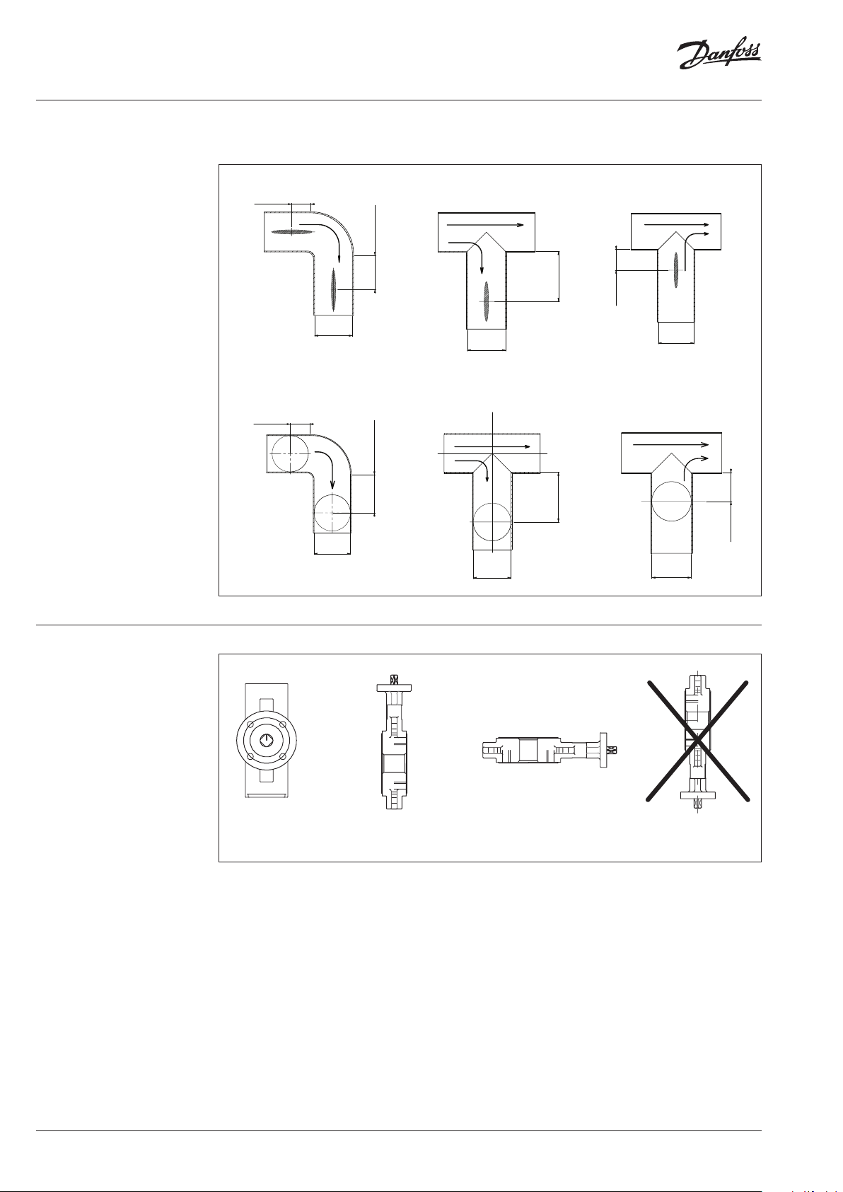
Installation conditions
It is recommended that distances indicated below are respected in order to prolong lifetime of the
valve. Mounting the valve close to pipework junctions (turbulent zones) increases wear.
5-6 DN
2-3 DN
DN
DN
1 DN
5-6 DN
1 DN
DN
2-3 DN
DN
DN
DN
1 DN
Installation positions
RecommendedRecommended
Possible
Not recommended
4 | AI361151079342en-010301 © Danfoss | 2021.05

Data sheet Danfoss Butterfly valve VFH2
30 50 70 90 100 110 120 130 10 -10 0
10
15
20
25
30
Design
P-T diagram
No. Description Materials
1 Body GGG40 nodular cast iron
2 Disc DN32: 304SS; DN40 -600: GGG40+Nylon
3 Stem Stainless steel 420
4 Valve Liner EPDM
5 Sealing ring EPDM
6 Guide bush PTFE
7 Clip ring Carbon steel
8 Screw Stainless steel
DN 32-350
Pressure (bar)
working range
5
0
Temperature (°C)
AI361151079342en-010301 | 5© Danfoss | 2021.05

Data sheet Danfoss Butterfly valve VFH2
Wiring
VFH2-WAO
ON/OFF
VFH2-WAM
Y & G
Heater
Grey
Brown
White
Brown
Grey
Black
Red
Blue
Full-close signal
(Pasive contac t)
Full-open signal
COM
Full-open signal
(Active contact)
Full-close signal
Open
Close
PE
MOD
Pink
RP
1K
Purple
Orange
Black
Red
Blue
Note:
Inside heating resistance adjust its own heat output based on internal temperature.
Semipermeable membrane help remove the moisture outside.
Output Signal
Input Signal
Power
Servo controller
Heater
+
−
+
−
L
N
PE
6 | AI361151079342en-010301 © Danfoss | 2021.05

Data sheet Danfoss Butterfly valve VFH2
L1
Dimensions
VFH2-WH
n- d1
D2
D1
3
2
H2 H1 H3
1
L
L H1 H2 H3 D1 D2 n-Φd1 a L1
DN
32 33 60 100 32 73 100 4-Φ19 45 19 5 1.78
40 33 55 143 32 76 11 0 4- Φ19 45 195 2.85
50 43 55 14 3 32 94 125 4- Φ19 45 195 3.06
65 46 66 156 32 107 14 5 4 -Φ19 45 19 5 3.74
80 46 72 162 32 126 160 8 -Φ19 22.5 195 4.11
100 52 90 181 32 15 7 180 4- Φ19 22.5 260 5.89
125 56 101 197 32 183 210 4- Φ19 22.5 260 7. 55
150 56 114 210 32 207 240 4-Φ23 22.5 260 8.55
mm
Weight
(kg)
AI361151079342en-010301 | 7© Danfoss | 2021.05

Data sheet Danfoss Butterfly valve VFH2
C 2
Dimensions (continuous)
VFH2-WG
H1 H2 H3 2
n- d1
D2
D1
L 2
a
a
L H1 H2 H3 D1 D2 n-Φd1 a C
DN
100 52 90 181 68 157 18 0 4 -Φ19 22.5 145 9.94
125 56 101 197 68 183 210 4 -Φ19 22.5 145 11 .61
150 56 114 210 68 207 240 4- Φ23 22.5 145 13 .39
200 60 154 240 74 265 295 4-Φ23 15 285 21.97
250 68 18 0 290 74 327 355 4 -Φ28 15 285 31.50
300 78 208 309 80 368 410 4 -Φ28 15 285 41.52
350 78 266 330 80 410 470 4 -Φ28 11. 25 285 45.19
400 102 294 361 103 478 525 4 -Φ31 11. 25 385 86.50
450 114 321 400 10 3 520 585 4- Φ31 9 385 105.00
500 127 350 465 140 575 650 4-Φ34 9 385 139.0 0
600 154 444 568 140 690 770 4-Φ37 9 385 235. 50
mm
Weight
(kg)
8 | AI361151079342en-010301 © Danfoss | 2021.05

Data sheet Danfoss Butterfly valve VFH2
a
L1
L2
Dimensions (continuous)
VFH2-WAO/WAM
n- d1
D1
D2
H1 H2 H3
a
L
L H1 H2 H3 D1 D2 n-Φd1 a L1 L2
DN
32 33 60 100 133 73 100 4- Φ19 45 160 13 7 4 .14 4.24
40 33 55 143 133 76 110 4-Φ19 45 16 0 137 5.41 5.51
50 43 55 14 3 133 94 125 4-Φ19 45 16 0 137 5.41 5. 51
65 46 66 156 133 107 145 4 -Φ19 45 16 0 137 5.82 5.92
80 46 72 162 133 126 160 8-Φ19 45 16 0 137 6.37 6.47
100 52 90 181 13 3 157 18 0 4- Φ19 22.5 160 137 8.10 8.20
125 56 101 197 16 0 18 3 210 4 -Φ19 22.5 196 150 11. 27 11 .57
150 56 114 210 160 207 240 4-Φ23 22.5 19 6 150 13 .05 13. 35
200 60 154 240 196 265 295 4- Φ23 15 255 182 22.85 23.15
250 68 18 0 290 196 327 355 4-Φ28 15 255 182 32.38 32.68
300 78 208 309 196 368 410 4-Φ28 15 255 182 40.52 40.82
350 78 266 330 196 410 470 4 -Φ28 11. 25 255 182 44.19 44.49
400 102 294 361 219 478 525 4 -Φ31 11. 25 310 241 79.90 80.20
450 114 321 400 219 520 585 4- Φ31 9 310 241 98 .90 99 .10
500 127 350 465 219 575 650 4-Φ34 9 310 241 11 6. 30 116 .6 0
600 154 444 568 239 690 770 4- Φ37 9 310 241 204.60 20 4.90
mm
Weight (kg)
AI361151079342en-010301 | 9© Danfoss | 2021.05

Data sheet Danfoss Butterfly valve VFH2
10 | AI361151079342en-010301 © Danfoss | 2021.05

Data sheet Danfoss Butterfly valve VFH2
AI361151079342en-010301 | 11© Danfoss | 2021.05

Data sheet Danfoss Butterfly valve VFH2
© Danfoss | DCS-S/SI | 2021.0512 | AI361151079342en-010301
 Loading...