

Page 1
Data sheet
Two- and three way valves VFG.. / VFGS 2 / VFU..
for self-acting thermostats and electrical actuators
Description
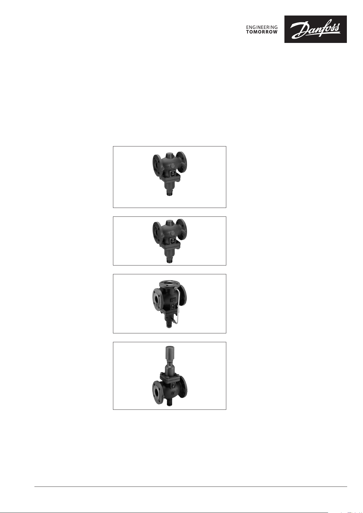
VFG 2
VFG 21
(see pages 2, 3, 4)
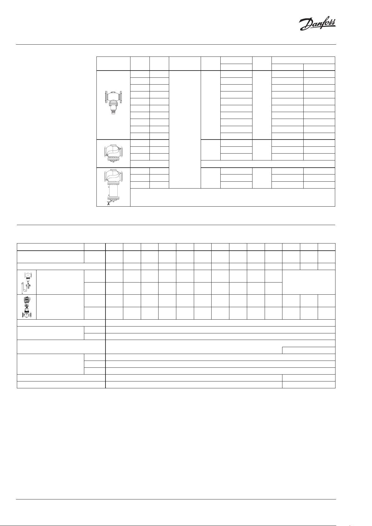
VFGS 2
(see pages 5, 6)
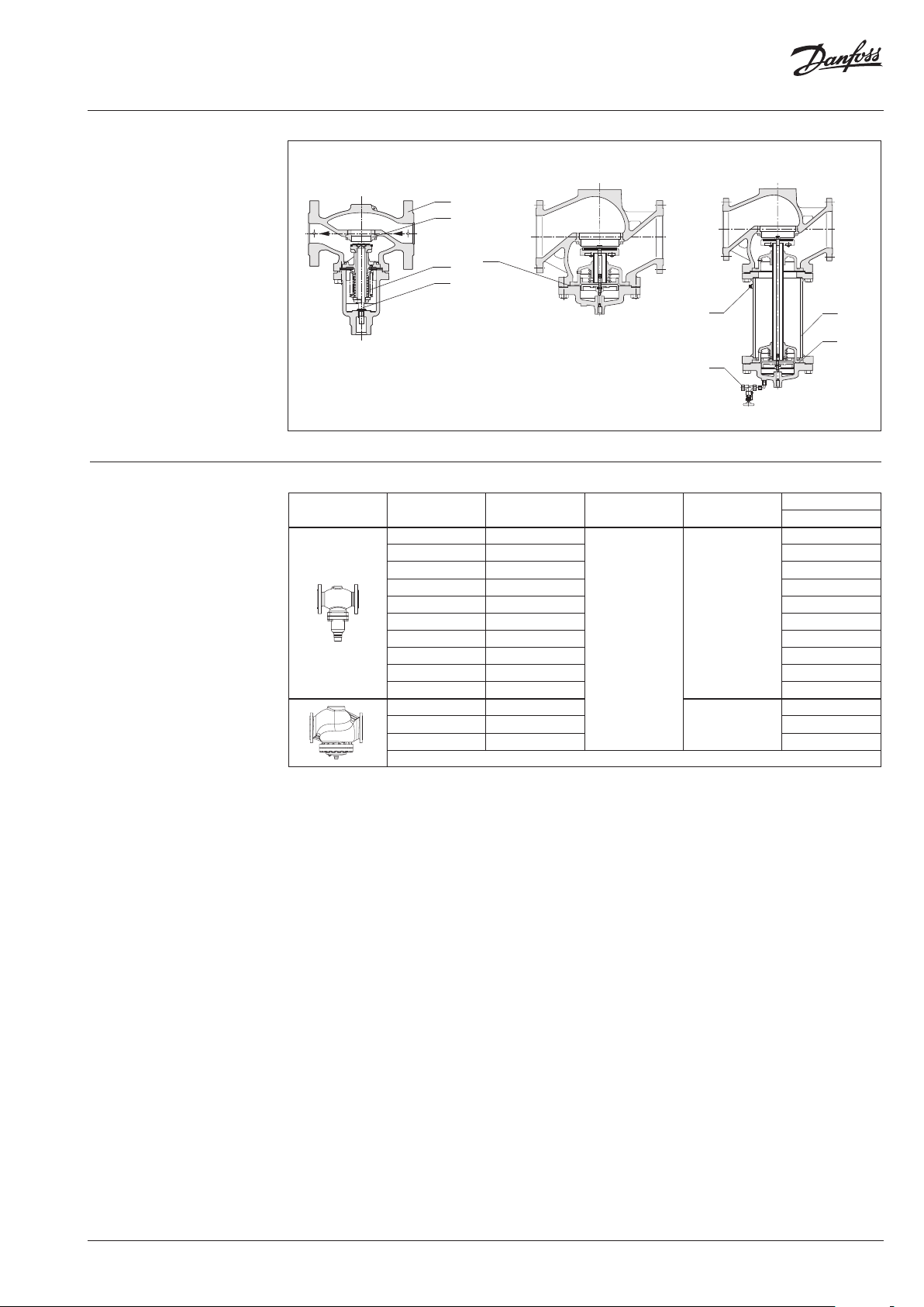
VFG 33
(see pages 6, 7)
Valves for heating, district heating and cooling
systems.
The valves can be used with following actuators:
• Thermostats AFT..
• Actuators AMV(E) 655, 658 , 659 (from Q4 2014)
Main data:
• DN 15-250
• T
200 °C
max
• 2-way valve (Normaly Open)
• Media:
circulation water and glycolic water up to 30%
• Cone:
VFG 2 metal/metal sealing
VFG 21 soft sealing
• Pressure relieved
Main data:
• DN 15-250
• T
350 °C
max
• 2-way valve (Normaly Open)
• Media: steam
• Cone: metal/metal sealing
• Pressure relieved
Main data:
• DN 25-125
• T
200 °C
max
• Media:
circulation water and glycolic water up to 30%
• mixing pressure balanced valve
• Cone: metal/metal sealing
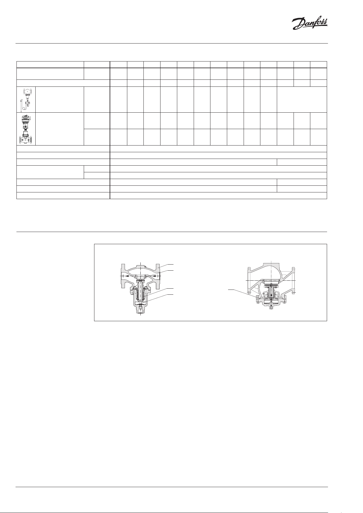
VFU 2
(see page 7, 8)
© Danfoss | 2018.10
Main data:
• DN 15-125
• T
150 °C
max
• 2-way valve (Normaly Close)
• Media:
circulation water and glycolic water up to 30%
• Cone: metal/metal sealing
• Pressure relieved
VD.LH.I4.02 | 1
Page 2
Data sheet Two- and three way valves VFG.. / VFGS 2 / VFU..
Ordering (VFG 2)
Cone:
metal /metal sealing, pressure
relieved.
Picture
DN
(mm)
k
VS
(m3 /h)
Connections
T
(°C)
15 4.0
20 6.3 065B2389 065B2402 065B2412
max
Code No.
PN 16 PN 25 PN 40
T
(°C)
max
065B2388
Code No.
065B2401 06 5B 2411
25 8.0 065B2390 065B24 03 06 5B2413
32 16 065B 2391 065B2404 065 B2414
40 20 065B2392 065B2405 06 5B2415
50 32 065 B2393 065B2406 065 B2416
65 50 065B2394 065B2407 06 5B2 417
80 80 065B2395 065B2408 065 B2418
100 125 065B2396 065B2409 065 B2419
125 160 065B2397 0 65B2 410 065B2420
Flanges acc. to
EN 1092-1
150 280
200 320 065B2399 – 065B2422
150
150
1)
1)
065B2398
200
150
1)
– 065B2421
1)
250 400 065B2400 – 065B2423
150 280
200 320 065B2425 – On request
150
1)
065B2424
200
1)
– On request
250 400 065B2426 – On request
1)
For detaile d temperature limits refe r to pressure/temperature di agram pg 9
Technical data (VFG 2)
Nominal diameter DN 15 20 25 32 40 50 65 80 100 125 150 200 250
280
kVS value (m3/h) 4 6.3 8 16 20 32 50 80 12 5 16 0
320
z value acc. to VDMA 24 422 0.6 0.6 0.6 0.55 0.55 0.5 0.5 0.45 0.4 0.35 0.3 0.2 0.2
2)
Δp
(bar) PN 16 16 16 16 16 16 16 16 16 15 15
max.
AFT PN 25, 40 20 20 20 20 20 20 20 20 15 15
320
1)
1)
450
400
630
1)
3)
Δp
(bar) PN 16 16 16 16 16 16 16 16 16 15 15 12 10 10
max.
AMV(E) 655, 658 , 659
(from Q4 2014)
Nominal pressure
4)
2)
Flow media/Temperature
Pressure balance Stainless steel bellow, mat. No.1.4571
PN 25, 40 20 20 20 20 20 20 20 20 15 15 12 10 10
PN 16, 25 flanges to EN 1092-2 or 40, flanges to EN 1092-1
PN 16 Circulation water / Glycolic water up to 30 % / thermo oil / 2 … 150 °C
PN 25, 40 Circulation water / Glycolic water up to 30 % / thermo oil / 2 … 200 °C
Rolling diaphragm
PN 16 Grey cast iron EN-GJL-250 (GG-25)
Valve body material
PN 25 Ductile iron EN- GJS-400 -18-LT (GGG- 40.3)
PN 40 Cast steel GP240GH (GS-C 25)
Cone material Stainless steel, mat. No. 1.4404 mat . No. 1.4021
Seat material Stainless steel, mat. No. 1.4021 mat. No. 1.4313
1)
In combinatio n with actuators AMV(E), kVS values are highe r if Y6 0 piece is removed from valve.
2)
Ab ove operating pressure of 14 bar use of valve ste m extension ZF4, ZF6 or combinati on piece KF2 is necessary.
3)
I n order the actuator can close at m ax differential pressu re flow velocity musn’t e xceed 2 m/s.
4)
With adapter : 065B3 527
2 | © Danfoss | 2018.10
VD.LH.I4.02
Page 3
Data sheet Two- and three way valves VFG.. / VFGS 2 / VFU..
1
Design (VFG 2)
1. Valve body
2. Valve seat
3. Bellows
4. Valve insert
5. Diaphragm
6. Valve body extension
7. Shut off valve for water filling
8. Closing plug
VFG 2 DN 15-125
2
5
3
4
VFG 2 DN 150-250
VFG 2 DN 150-250, T
max
200 °C
Ordering (VFG 21)
Cone:
soft sealing, pressure relieved.
Picture
8
6
5
7
DN
(mm)
15 4.0
20 6.3 065B2503
25 8.0 065B2504
32 16 065B2505
40 20 065B2506
50 32 065B2507
65 50 065B2508
80 80 065B2509
100 125 065B2 510
125 160 06 5B2 511
150 280
200 320 065B2513
250 400 065B 2514
k
VS
(m3 /h)
Connections
Flanges acc. to EN
1092-1
T
(°C)
150
150
max
Code No.
PN 16
065B2502
06 5B2512
VD.LH.I4.02
© Danfoss | 2018.10 | 3
Page 4
Data sheet Two- and three way valves VFG.. / VFGS 2 / VFU..
1
Technical data ( VFG 21)
Nominal diameter DN DN 15 20 25 32 40 50 65 80 100 125 150 200 250
280
kVS value (m3/h) 4 6.3 8 16 20 32 50 80 125 16 0
z value acc. to VDMA 24 422 0.6 0.6 0.6 0.55 0.55 0.5 0.5 0.45 0.4 0. 35 0.3 0.2 0.2
2)
Δp
(bar) PN 16 16 16 16 16 16 16 16 16 15 15
max.
Δp
(bar) PN 16 16 16 16 16 16 16 16 16 15 15 12 10 10
max.3)
320
320
1)
1)
450
400
630
1)
AMV(E) 655, 658 , 659
(from Q4 2014)
Nominal pressure
4)
2)
PN 25 20 20 20 20 20 20 20 20 15 15 12 10 10
PN 16 or 25, flanges to EN 1092-2
Flow media/Temperature Circulation water / Glycolic water up to 30 % / 2 … 150 °C
Pressure balance Stainless steel bellow, mat. No.1.4571 Rolling diaphragm
Valve body material
PN 16 Grey cast iron EN-GJL-250 (GG-25)
PN 25 Ductile iron EN- GJS-400 -18-LT (GGG- 40.3)
Cone material Stainless steel, mat. No. 1.4404 mat . No. 1.4021
Seat material Stainless steel, mat. No. 1.4021 mat. No. 1.4313
Conical seal EPDM
1)
in combinatio n with actuators AMV(E), kVS values are highe r if Y6 0 piece is removed from valve.
2)
above operati ng pressure of 14 bar use of valve stem extensi on ZF4, ZF6 or combination piece KF2 is ne cessary.
3)
I n order the actuator can close at m ax differential pressu re flow velocity musn’t e xceed 2 m/s.
4)
With adapter : 065B3 527
Design (VFG 21)
VFG 21 DN 15-125 VFG 21 DN 150 -250
1 Valve body
2 Valve seat
3 Bellow
2
4 Valve insert
5 Diaphragm
3
5
4
4 | © Danfoss | 2018.10
VD.LH.I4.02
Page 5

Data sheet Two- and three way valves VFG.. / VFGS 2 / VFU..
Ordering (VFGS 2 – for steam)
Cone: metal/metal sealing, pressure relieved.
Picture
DN
k
(mm)
VS
(m3/h)
15 4.0 2.5
k
VS
(m3/h)
1)
Connections
T
max
(° C)
Code No.
PN 16 PN 25 PN 40
T
max
(° C)
065B2430
Code No.
065B2443 065B2453
20 6.3 4.0 065 B2431 065B2444 065B2454
25 8.0 6.3 065B2432 065B2445 065B2455
32 16 10 065B2433 065B2446 065B2456
40 20 16 065B2434 065B2 447 065B2457
50 32 25 065B2435 065B2448 065B2458
65 50 40 065B2436 065B2449 065B2459
80 80 63 065B24 37 065B2450 0 65B2460
Flanges acc. to
EN 1092-1
150
2)
350
2)
100 125 100 065B2438 0 65B2451 06 5B2461
125 160 125 065B2439 0 65B2452 065B2462
150 3)280 200
200 3)320 225 065 B2441 – 065B2464
150
2)
065B2440
300
2)
– 065B2463
250 3)400 280 065B2442 – 065B2465
1)
Va lves with flow divider fo r noise reduction (see accessorie s)
2)
for d etailed temperature limi ts refer to pressure/tempe rature diagram pg 9
3)
Valve has valve body e xtension (VBE) and p re-installed flow div ider
Technical data (VFGS 2)
Nominal diameter DN 15 20 25 32 40 50 65 80 100 125 15 0 200 250
280
kVS value (m3/h) 4 6.3 8 16 20 32 50 80 125 160
1)
kVS value
(m3/h) 2.5 4.0 6.3 10 16 25 40 63 100 125 200 225 280
320
z value acc. to VDMA 24 422 0.6 0.6 0.6 0. 55 0.55 0.5 0.5 0.45 0.4 0.35 0.3 0.2 0.2
3)
Δp
(bar) PN 16 16 16 16 16 16 16 16 16 15 15
max.
AFT
PN 25, 40
20 20 20 20 20 20 20 20 15 15
320
2)
2)
450
400
630
2)
4)
Δp
(bar) PN 16 16 16 16 16 16 16 16 16 15 15 12 10 10
max.
AMV(E) 655, 658, 659
(from Q4 2014)
Nominal pressure
3)
Flow media/Temperature
5)
PN 25, 40 20 20 20 20 20 20 20 20 15 15 12 10 10
PN 16, 25 flanges to EN 1092-2 or 40, flanges to EN 1092-1
PN 16 Steam / max. 150 °C
PN 25, 40 Steam / max. 350 °C
Steam / max. 30 0 °C
Pressure balance Stainless steel bellow, mat. No.1.4571 Rolling diaphragm
PN 16 Grey cast iron EN-GJL-250 (GG-25)
Valve body material
PN 25 Ductile iron EN- GJS-400 -18-LT (GGG- 40.3)
PN 40 Cast steel GP240GH (GS-C 25)
Cone material Stainless steel, mat. No. 1.4021 mat. No. 1.4313
Seat material Stainless steel, mat. No. 1.4021
1)
Valves with flow d ivider for noise reduc tion (see accessories)
2)
In co mbination with actuator s AMV(E), kVS values are highe r if Y6 0 piece is removed from valve.
3)
Above operati ng pressure of 14 bar use of valve stem extensi on ZF4, ZF6 or combination piece KF2 is ne cessary.
4)
In o rder the actuator can close at m ax differential pressu re flow velocity musn’t e xceed 2 m/s.
5)
Wi th adapter: 065B3 527
VD.LH.I4.02
© Danfoss | 2018.10 | 5
Page 6

Data sheet Two- and three way valves VFG.. / VFGS 2 / VFU..
1
Design (VFGS 2)
1. Valve body
2. Valve seat
3. Bellow
4. Valve insert
5. Diaphragm
6. Valve body extension
7. Shut off valve for water filling
8. Closing plug
Ordering (VFG 33)
VFGS 2 DN 15-125
2
3
4
VFG 33 (mixing valve – pressure balanced)
Picture
DN
(mm)
25 8.0
32 12. 5 065B2599 065B2607
40 20 065B2600 065B2608
50 32 0 65B2601 065B2609
65 50 065B2602 065B2610
80 80 065B2603 065B2611
100 125 065B2604 065B2612
125 160 065B2605 065B2613
1)
for detailed te mperature limits refer to pr essure/temperature ratings d iagram pg 9
k
VS
(m3/h)
Connections
Flanges acc.
to EN 1092-1
T
(°C)
150
max
1)
VFGS 2 DN 150-250
8
6
5
7
Code No.
PN 16 PN 25
065B2598
T
(°C)
200
max
1)
Code No.
065B2606
Technical data (VFG 33)
Nominal diameter DN 25 32 40 50 65 80 10 0 125
k
value (m3/h) 8 12. 5 20 32 50 80 125 160
VS
1)
Δp
max.
AFT
2)
Δp
max.
AMV(E) 655, 658, 659
(from Q4 2014)
Nominal pressure
1)
Flow media/Temperature
(bar)
(bar) PN 16 16 16 16 16 16 16 15 15
3)
PN 16 16 16 16 14 12 10 10 10
PN 25 18 18 16 14 12 10 10 10
PN 25, 40 20 20 20 20 20 20 15 15
PN 16 or 25, flanges to EN 1092-2
PN 16 Circ.water / Glycolic water up to 30 % / 2 … 150 °C
PN 25 Circ.water / Glycolic water up to 30 % / 2 … 200 °C
Pressure balance Stainless steel bellow, mat. No.1.4571
Valve body material PN 16, 25 Ductile iron EN-GJS-400-18-LT (GGG-40. 3)
Cone material Stainless steel, mat. No. 1.4404
Seat material Stainless steel, mat. No. 1.4021
1)
Above operati ng pressure of 14 bar use of valve stem exte nsion ZF4, ZF6 or combination piece KF2 is n ecessary.
2)
I n order the actuator can close at m ax differential pressu re flow velocity musn’t e xeed 2 m/s.
3)
Wi th adapter: 0 65B3527
6 | © Danfoss | 2018.10
VD.LH.I4.02
Page 7

Data sheet Two- and three way valves VFG.. / VFGS 2 / VFU..
B
B
A
Applications (VFG 33)
Design (VFG 33)
1 Valve body
2 Valve seat
3 Bellow
4 Valve insert
B
AB
A
Heating Cooling
Mixing valve used in mix ing application
A
AFT06 / VFG 33
1
B
AB
A
Mixing valve used in diverting application
Ordering (VFU 2)
Opening valve, pressure relieved.
2
3
4
VFU 2 (metallic sealing cone)
Picture
1)
For detaile d temperature limits refe r to pressure/temperature di agram pg 9
DN
(mm)
15 4.0
20 6.3 065B2739
25 8.0 065B274 0
32 16 0 65B2 741
40 20 0 65B2742
50 32 065 B2743
65 50 0 65B2 744
80 80 065B 2745
100 125 065B274 6
125 160 0 65B2747
k
VS
(m3/h)
Connections
Flanges acc. to EN
1092-1
T
(°C)
150
max
Code No.
PN 16
065B2738
1)
VD.LH.I4.02
© Danfoss | 2018.10 | 7
Page 8

Data sheet Two- and three way valves VFG.. / VFGS 2 / VFU..
Technical data (VFU 2)
Design (VFU 2)
1 Valve body
2 Valve seat
3 Valve insert
4 Bellow
Nominal diameter DN 15 20 25 32 40 50 65 80 100 125
kVS value (m3/h) 4 6.3 8 16 20 32 50 80 125 16 0
z value acc. to VDMA 24 422 0.6 0.6 0.6 0.55 0. 55 0.5 0.5 0.45 0.4 0.35
Δp
(bar)
max.
AF T..
Δp
(bar)
max.
AMV(E) 655, 658, 659
(from Q4 2014)
1)
PN 16 10 8
PN 16 12 10 8
Nominal pressure PN 16, flanges to EN 1092-2
Flow media/Temperature Circulation water / Glycolic water up to 30 % / 2 … 150 °C
Pressure balance Stainless steel bellow, mat. No.1.4571
Valve body material Grey cast iron EN-GJL-250 (GG-25)
Cone material/Conical seal Stainless steel, mat. No. 1.4404
Seat material Stainless steel, mat. No. 1.4021
1)
With adapter : 0 65B3527
4
3
2
Accessories
Remark:
Temperature controller with thermostat
AF T..:
This controlle r can be used until
operating pre ssure of 14 b ar. If the
operating pre ssure is higher than 14 bar
the valve stem ex tension ZF4, ZF6 or the
combination p iece KF2 must be used.
1
Picture Ty pe Note Code No.
Comb. piece KF2 For combinations with thermostats 0 03G14 40
Comb. piece KF3
Valve stem extension ZF4 Valves DN 15-125
For combinations with thermostats, pressure controllers
and motorised actuators
For water, steam above 200 °C 003G1394
00 3G1441
For oil above 200°C 003G1395
Valve stem extension ZF5 Valves DN 15-125 For water, steam or oil above 200 °C 003G1396
Valve stem extension ZF6 For water, steam temperatures until 200 °C 003G1393
Flow divider for VFGS 2
(for noise reduction)
DN k
VS
15 4 2.5
20 6.3 4
25 8 6.3
32 16 10
40 20 16
50 32 25
65 50 40
80 80 63
100 125 10 0
125 160 125
reduced k
VS
Code No.
065B2775
065B2776
065B2777
065B2778
065B2779
8 | © Danfoss | 2018.10
VD.LH.I4.02
Page 9

Data sheet Two- and three way valves VFG.. / VFGS 2 / VFU..
Pressure temperature
diagram
Working area is below P-T line
and it ends at T
for each valve
max
VFG/VFU/VFGS PN 16
EN -GJL-2 50
(GG -25)
Maximum allowed operating pressure as a function of media temperature (according to EN 1092-2)
VFG PN 25
EN-GJS- 400
(GGG-40.3)
Maximum allowed operating pressure as a function of media temperature (according to EN 1092-2)
VFG PN 40
VFGS PN 25
120
VFGS PN 40
EN-GJS-400
(GGG-40.3)
EN-GP-240-GH
(GS- C 25)
120
Maximum allowed operating pressure as a function of media temperature (according to EN 1092-1)
EN-GP-240-GH
(GS- C 25)
VD.LH.I4.02
© Danfoss | 2018.10 | 9
Page 10

Data sheet Two- and three way valves VFG.. / VFGS 2 / VFU..
Dimensions
L
H
B
VFG(S) DN 15-125
L
L
H
B
1
H
1
VFG DN 150-250
B
VFG(S) DN 150 -250
with valve body extension
up to 200 (300) °C
VFG 2, VFG 21, VFGS 2 Valves
DN 15 20 25 32 40 50 65 80 10 0 125 150 200 250
L
B 213 213 239 239 241 241 276 276 381 381 326 354 401
H 267 267 304 304 323 323 370 370 505 505 505 591 6 61
Weight
B
H
Weight (valve
with body
extension)
PN 16 / 25
PN 40 30 32.5 60.5 69 141 253 333
1
1
PN 16 / 25
PN 40 179 336 505
130 150 160 180 200 230 290 310 350 400 480 600 730
mm
kg 7. 5 8.5 10 12 15 18
mm
kg
27. 5 30 58 68 115 185 323
620 852 119 9
700 994 1359
154 3 01 469
10 | © Danfoss | 2018.10
VD.LH.I4.02
Page 11

Data sheet Two- and three way valves VFG.. / VFGS 2 / VFU..
B
L
C
L/2
L
70
120
90
180
Dimensions (continuous)
B
VFU 2
DN 15-12 5
VFG 33
DN 25-125
VFG 33 valves
DN 25 32 40 50 65 80 100 125
L
B 238 238 24 0 240 275 275 380 380
160 180 200 230 290 310 350 400
mm
Weight kg 10. 5 12 17 21 35 41 75 93
VFU 2 valve
DN 15 20 25 32 40 50 65 80 100 12 5
L
B 95 95 106 106 123 12 3 135 135 165 165
C 306 306 332 332 334 334 369 369 474 474
Weight kg 7. 0 9.0 10 13 17 22 33 41 70 79
130 150 160 180 200 230 290 310 350 400
mm
VD.LH.I4.02
Comb. piece KF2 , KF3
Valve stem extension
ZF4, ZF5
Valve stem extension
ZF6
© Danfoss | 2018.10 | 11
Page 12

Data sheet Two- and three way valves VFG.. / VFGS 2 / VFU..
12 | © Danfoss | DHS-SRMT/SI | 2018.10
VD.LH.I4.02
 Loading...