

Page 1
Data sheet
Seated valves (PN 16)
VF 2 - 2-way valve, flange
VF 3 - 3-way valve, flange
Description
VF 2 and VF 3 valves provide a quality, cost
effective solution for most water and chilled
applications.
The valves are designed to be combined with
following actuators:
• DN 15-50 with AMV(E) 335, AMV(E) 435 or AMV(E)
438 SU actuators.
With AMV(E) 25 (SU/SD) or AMV(E) 35
actuators (with adapter 0 65Z 0311)
• DN 65, 80 with AMV(E) 335 or AMV(E) 435 actuators.
With AMV(E) 56 actuator (with adapter
065Z0312)
• DN 100 with AMV(E) 55/56 or AMV(E) 65x
actuators
• DN 125, 150 with AMV(E) 55/56, AMV(E) 65x or
AMV(E) 85/86 actuators
• DN 200-300 with AME 685 or AME 855 actuators
Features:
• Soft sealing design DN15-80, 200-300
• Snap mechanical connection together with
AMV(E) 335, AMV(E) 435
• Dedicated 2 and 3-port valve
• Suitable for diverting applications (3-port)
Main data:
• DN 15-300
• kVS 0.63 -1350 m3/h
• PN 16
• Up to close A-AB
• Down to close A-AB (VF 3 DN 200-300)
• Temperature:
• Circulation water/glycolic water up to 50 %:
2 (–10*) … 130 °C (DN 15-100)
2 (–10*) … 200 °C (DN 125, 150)
2 (–10*) … 130 °C (DN 200-300)
* At temperature s from −10 °C up to +2 °C use stem heater
• Flange connections PN 16
• Compliance with Pressure Equipment
Directive 97/23/EC
© Danfoss |2021.10
Combinations of actuators is evident under
section “Dimension”.
AI244286498524en-010204 | 1
Page 2
Data sheet Seated valves VF 2, VF 3
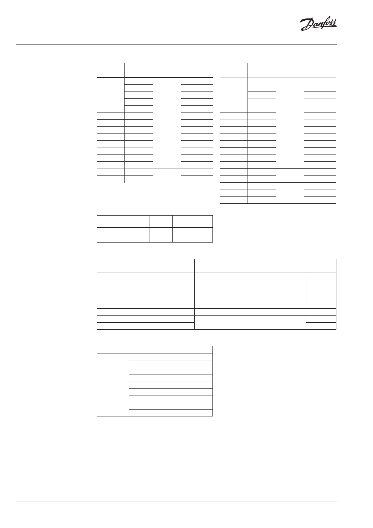
Ordering
Example:
2-way valve; DN 15; kVS 1.6 ; PN 16;
T
130 °C; flange connection;
max
- 1× VF 2 DN 15 valve
Code No.: 065Z0273
2-way valve VF 2
k
DN
15
20 6.3 065Z0276
25 10 065Z0277
32 16 065Z0278
40 25 065Z0279
50 40 065Z0280
65 63 065Z0281
80 100 065Z0282
100 145 065B3205
125 220
150 320 065B3255
VS
(m3/h) (oC)
0.63
1.0 065Z0272
1.6 065Z0273
2.5 065Z0274
4.0 065Z0275
T
130
200
max.
Accessories - Adapter
DN Actuators
15- 50 AMV(E) 25, 35 4.0 06 5Z0311
65-80 AMV(E) 56 2.5 065Z0 312
max.∆p
(bar)
Code No.
Code No.
065Z0271
065B3230
3-way valve VF 3
k
DN
15
20 6.3 065Z0256
25 10 065Z0257
32 16 065Z0258
40 25 065Z0259
50 40 065Z0260
65 63 0 65Z02 61
80 100 065Z0262
100 145 065 B1685
125 220
150 320 065B3150
200 630
250 1000 065B4250
300 1350 065B4300
VS
(m3/h) (oC)
0.63
1.0 065Z0252
1.6 065Z0253
2.5 065Z0254
4.0 065Z0255
T
130
200
130
max.
Code No.
065Z0251
06 5B3125
065B4200
Accessories - Stem heater
DN Actuators
15- 80 AMV(E) 335, 435
15- 50 AMV(E) 438 SU enclosed
15- 50 AMV(E) 25/35 06 5Z0311
65-80 AMV(E) 56 06 5Z0312
100 AMV(E) 55, 56, 65x 24/ 15 065Z7020 /
125 , 150 AMV(E) 55, 56, 65x 24/40 065Z7022 /
125 , 150 AMV(E) 85, 86
200-300 AME 685, 855 /
Power supply
(V/ VA)
24/40 065Z0315
24/20 06 5Z7021
Code No.
Stem Heater Adapter
Service kits
Typ e DN
Stuffing box
15 065Z0 321
20 065Z0322
25 065Z0323
32 065Z0324
40, 50 065Z0325
65, 80 065Z0327
100 065 B1360
125 , 150 065B0007
200-300 065B3530
Code No.
/
/
2 | AI244286498524en-010204
© Danfoss | 2021.10
Page 3
Data sheet Seated valves VF 2, VF 3
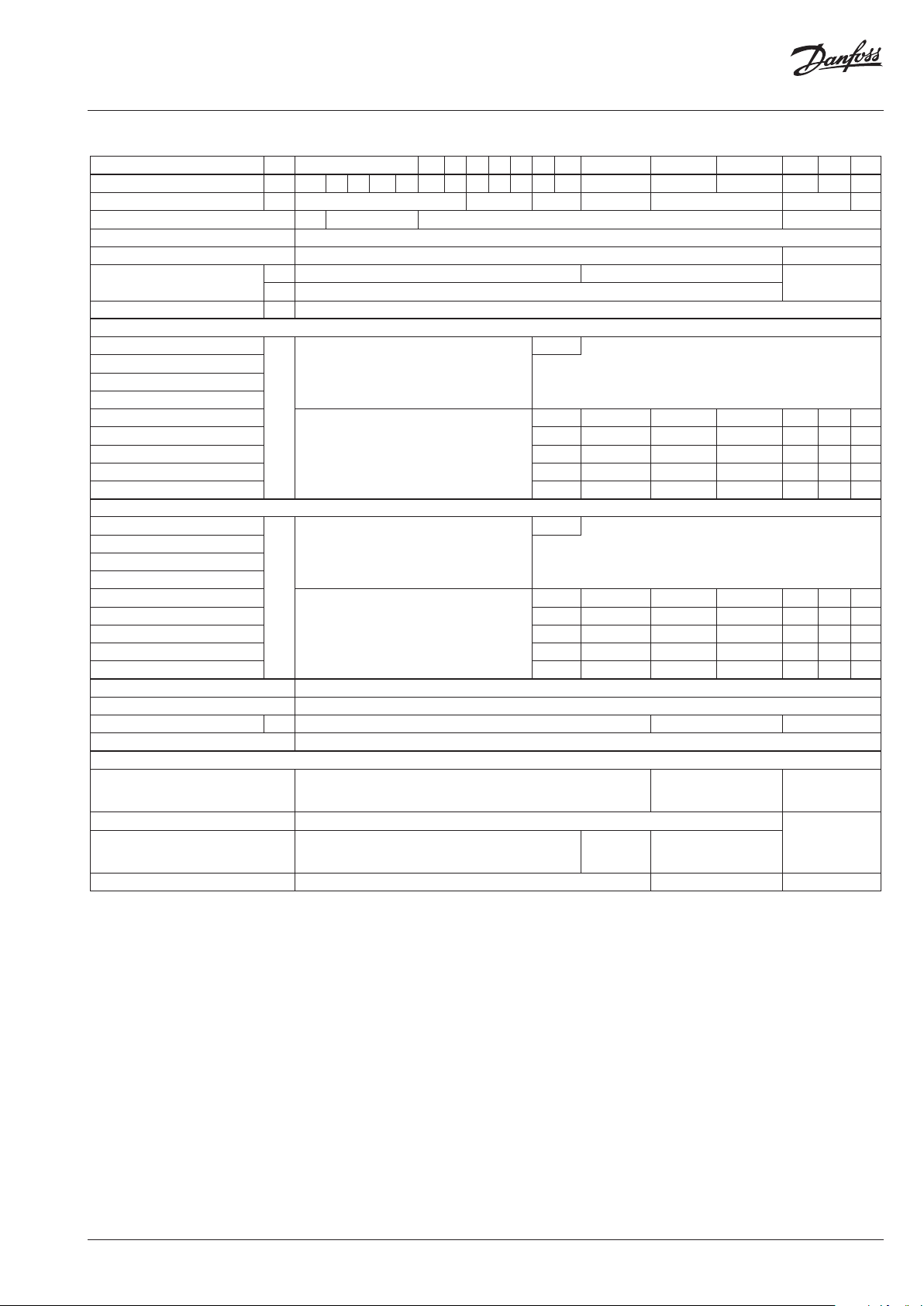
Technical data
Nominal diameter DN 15 20 25 32 40 50 65 80 100 125 150 200 250 300
k
value m3/h 0.63 1.0 1. 6 2.5
VS
Stroke mm 10 15 20 30 40 57 73
Control range
30:1 50:1 100 :1 >50:1
Control characteristic
Cavitation factor z ≥ 0.4 ≥0.45
Leakage
A-AB
B-AB ≤ 1.0 % of kVS
Nominal pressure PN 16
Max. closing pressure
1)
for VF 2 (up to DN 150) and for VF 3 (in mixing applications)
AMV(E) 335/435 (4 00 N)
AMV(E) 25 (SU/SD)/438 SU
(450 N)
AMV(E) 35 (600 N)
AMV(E) 25 (1000 N)
AMV(E) 55/65x (2000 N)
bar
AMV(E) 56 (1500 N)
AMV(E) 85/86 (5000 N) - -
AME 685 (5000 N) - - - - 1.5
AME 855 (15000N) - - - - 5.0 4.0 2.5
Max. closing pressure
1)
for VF 3 (diverting applications)
AMV(E) 335/435 (4 00 N)
AMV(E) 25 (SU/SD)/438 SU (450 N)
AMV(E) 35 (600 N)
AMV(E) 25 (1000 N)
AMV(E) 55/65x (2000 N)
bar
AMV(E) 56 (1500 N)
AMV(E) 85/86 (5000 N) - -
AME 685 (5000 N) - - - - 1.2 1.0 0.5
AME 855 (15000N) - - - - 4.0 3.5 2.0
Medium Circulation water/glycolic water up to 50 %
Medium pH Min. 7, Max. 10
Medium temperature
2) o
C 2 (–10) … 130 2 (–10) … 200 2 (–10) … 130
Connections Flange PN 16 acc. to EN 1092-2
Materials
Valve body
Valve stem Stainless steel
Valve cone Brass
Stung box sealing
1)
Maximu m permissible differ ential pressure across the valve re ferred for the whole act uating range of motorised valve (a fu nction of actuator ’s performance)
2)
At tem peratures from –10 up to +2 °C use stem heater
4.0
6.3 10 16 25 40 63 100 145 220 320 630 1000
LOG: port A-AB; LIN: por t B-AB
≤ 0.03 % of kVS ≤ 0.05 % of k
VS
2.5
4
-
1.5 1.0 0.5
-
2.5 1. 0 0.5 0.2
-
3.0 1. 5
0.6
1
-
0.3 0.6 0.5
-
0.6 0.3 0.5 0.2
-
Grey cast iron
EN-GJL-250 (GG -25)
0.6 0.6
Ductile iron
EN-GJS-400-18-LT
(GGG 40.3)
Red bronze
CuSn5Zn5Pb5
GGG 40
(Rg 6)
EPDM PFTE EPDM
≤ 0.01 % of k
- - -
- - -
- - -
1.2
- - -
- - -
- - -
Grey cast iron
EN -G JL-2 50 (GG -
25)
non-magnetic
stainless steel
1350
VS
0.8
© Danfoss | 2021.10
AI244286498524en-010204 | 3
Page 4
Data sheet Seated valves VF 2, VF 3
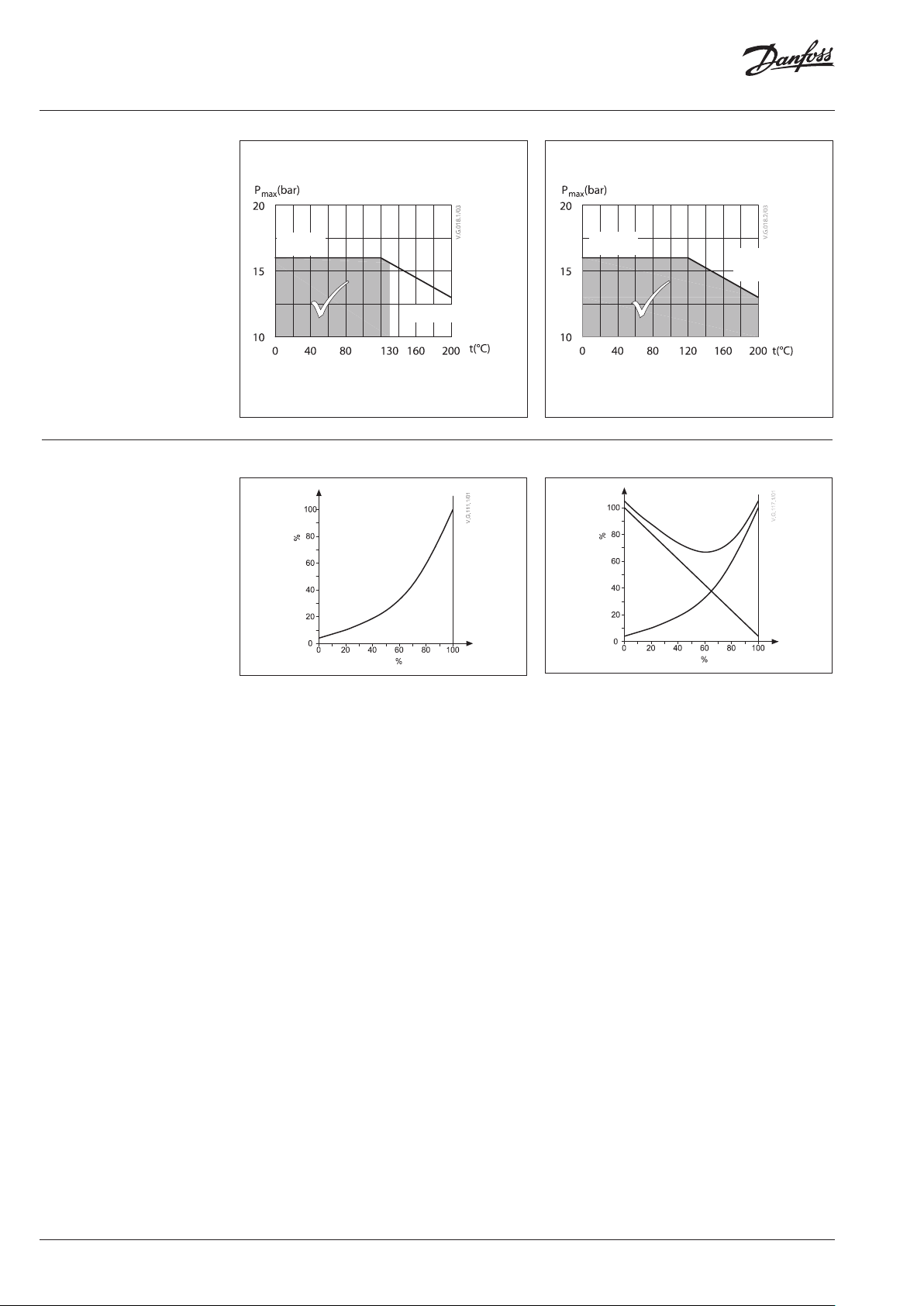
Pressure temperature
diagram
Valve characteristics
DN 15-100
DN 125-15 0
DN 200-300
PN 16
PN 16
EN-GJS-400-18-LT
(GGG 40.3)
EN- GJ L-250 ( GG-25 )
Maximum allowed operating pressure as a function of
medium temperature (according to EN 1092-2)
Maximum allowed operating pressure as a function of
medium temperature (according to EN 1092-2)
Valve characteristics log (2-way) Valve characteristics log/lin (3-way)
A+BAB
B
Capacity
AB
2-way A
Capacity
AB
AB
A
Stroke
Stroke
4 | AI244286498524en-010204
© Danfoss | 2021.10
Page 5
Data sheet Seated valves VF 2, VF 3
Installation
AMV(E) 335/435 AMV(E) 25(SU/SD)/ 35/438 SU
AMV(E) 55/56 AMV(E) 85/86
7 mm
AMV(E) 65x, 685
7 mm
7 mm
7 mm
AME 855
© Danfoss | 2021.10
AI244286498524en-010204 | 5
Page 6

Data sheet Seated valves VF 2, VF 3
Installation (continuous)
Tmax≤150 °C for AMV(E) 25 (SU/SD), 35
Tmax≤200 °C for other AMV(E)
Tmax = 150 ... 200 °C AMV(E) 25 (SU/SD), 35
Valve mounting
Before mounting the valve be sure that the pipes
are clean and free from abrasion.
It is essential that the pipes are lined up squarely
with the valve at each connection and that they
are free from vibrations.
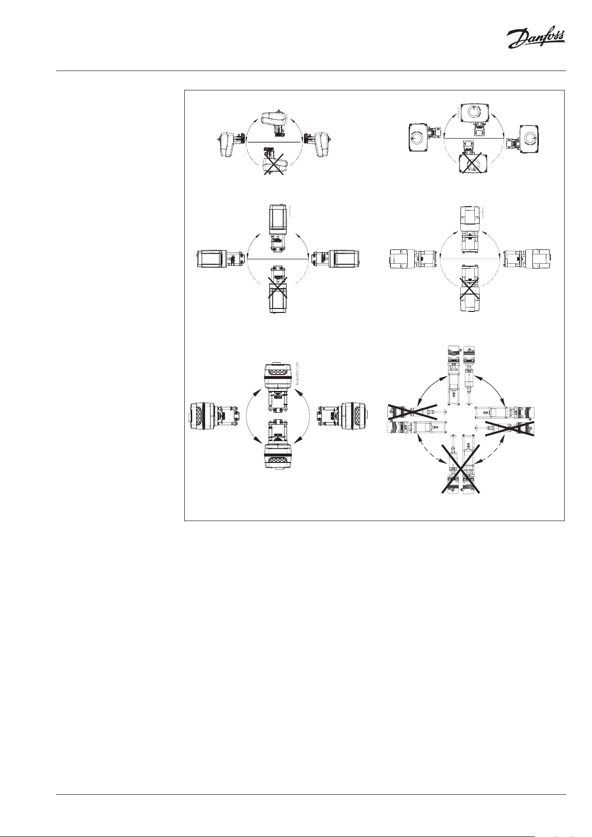
Install the motorized control valves with the
actuator in a vertical or horizontal position in
accordance to recommendations described in
Installation above.
Leave sufficient clearance to facilitate the
dismantling of the actuator from the valve body
for maintenance purposes.
Note that the actuator may be rotated up to 360°
with respect to the valve body by loosening the
retaining fixture. After this operation retighten.
Mixing
Diverting
Always install the valve with the arrow on
the body in the same direction as the flow. In
order to avoid turbulence, which will affect the
measuring accuracy, it is recommended to have a
straight length of pipe up and down stream from
the valve as shown (D - diameter of pipe).
Note:
Install a strainer upstream of the valve
(e.g. Dan foss FVR/FV F)
5D
FVR/FVF
Fig. 3: Mixing valve used in diver ting applicationFig. 1: Mixing or diverting connection
2D
AMV(E)
5D
Fig. 2: Mixing valve used in mixing application
Mixing or diverting connection
3-way valve can be used either as mixing or
diverting valve (fig.1).
If 3-way valve is installed as mixing valve
meaning that A and B ports are inlet ports, and
AB port is outlet port it can be installed in mixing
(fig.2) or diverting application (fig.3).
Fig. 4: Diver ting valve used in divertin g application
3-way valve can be also installed as diverting
valve in diverting application (fig.4) meaning that
AB port is inlet and A and B ports are outlets.
Note:
Maximal closing pressure for mixing and diverting
insta llation are no t the same. Plea se refer to value s stated
in Technical data section.
6 | AI244286498524en-010204
© Danfoss | 2021.10
Page 7

Data sheet Seated valves VF 2, VF 3
21
1
pp
p
a authority, Valve
5.0
p2
p
a
2
1
=
∆×
∆
=
62.0
557.90
7.90
authority valve hence
50.39
5536
36
authority valve hence
Sizing
Flow Rate
(liquid w ith specific a gr avity of 1)
l/sec m3/h
max
Δp
FLOW Pressure d rop kPa (100 kPa = 1bar = ~ 10 m H2O)
Example
Design data:
Flow rate: 6 m3/h
System pressure drop: 55 kPa
Locate the horizontal line representing a flow
rate of 6 m3/h (line A-A). The valve authority is
given by the equation:
Where:
Δp1 = pressure drop across the fully open valve
Δp2 = pressure drop across the rest of the circuit
with a full open valve
The ideal valve would give a pressure drop equal to
the system pressure drop (i.e. an authority of 0.5 ):
if: Δp1 = Δp
2
In this example an authority of 0.5 would be
given by a valve having a pressure drop of
55 kPa at that flow rate (point B). The intersection
of line A-A with a vertical line drawn from B lies
between two diagonal lines; this means that no
ideally-sized valve is available.
The intersection of line A-A with the diagonal
lines gives the pressure drops stated by real,
rather than ideal, valves. In this case, a valve with
kVS 6.3 would give a pressure drop of 90.7 kPa
(point C):
The second largest valve, with kVS 10, would give
a pressure drop of 36 kPa (point D):
Generally, for a 3 port application, the smaller
valve would be selected (resulting in a valve
authority higher than 0.5 and therefore
improved control). However, this will increase
the total pressure and should be checked by the
system designer for compatibility with available
pump heads, etc. The ideal authority is 0.5 with a
preferred range of between 0.4 and 0.7 .
© Danfoss | 2021.10
AI244286498524en-010204 | 7
Page 8

Data sheet Seated valves VF 2, VF 3
Design
(Design variati ons are possible)
VF 2 DN 15-80
1. Valve body
2. Valve cover
3. Valve cone
4. Valve stem
5. Moving valve seat
(pressure relieved)
6. Stuffing box
VF 3 DN 15-80
1. Valve body
2. Valve cover
3. Valve cone
4. Valve stem
5. Valve seat
6. Pressure relieve chamber
7. Stuffing box
VF 2 DN 100
1. Valve body
2. Stuff ing box
3. Valve cone
4. Valve stem
5. Blind flange
VF 3 DN 100
1. Valve body
2. Stuff ing box
3. Valve cone
4. Valve stem
VF 2 DN 125-150
1. Valve body
2. Stuff ing box
3. Valve cone
4. Valve stem
5. Blind flange
VF 3 DN 125-150
1. Valve body
2. Stuffing box
3. Valve cone
4. Valve stem
8 | AI244286498524en-010204
© Danfoss | 2021.10
Page 9

Data sheet Seated valves VF 2, VF 3
Design (continuous)
VF 3 DN 200-300
1. Stem
2. Stuffing box
3. Insert body
4. Valve body
5. Seat A
6. Studdle stem
7. Cone component
8. Seat B
9. Support stem
10. Valve body extension
© Danfoss | 2021.10
AI244286498524en-010204 | 9
Page 10

Data sheet Seated valves VF 2, VF 3
Dimensions
45°
22.5 °
k
d2
VF 2 (DN 15-65)
AMV(E) 335, 435 +
VF 2 (DN 15-80)
k
H
n
d2
H
n
VF 2 (DN 80)
mi n. 150
min. 20.5
1
H
H
L
AMV(E) 438 SU +
VF 2 (DN 15-50)
AMV(E) 25 (SU/SD),35 +
min . 100
3
H
2
H
H
L
L
H
AMV(E) 56 +
VF 2 (DN 65-80) +
adapter 065Z0312
VF 2 (DN 15-50) +
adapter 065Z0311
Typ e DN
15 13 0 47. 5 191 216 - 65 14 4 1.93
20 150 52.5 19 4 218 - 75 14 4 2.65
25 160 57. 5 197 222 - 85 14 4 3.23
VF 2
Note:
If stem heater is use d dimension H1 is increased for 28 m m and H2 for 32 mm.
32 180 70 202 226 - 100 19 4 4.97
40 200 75 213 237 - 11 0 19 4 6.59
50 230 82.5 218 242 - 125 19 4 8.53
65 290 92.5 254 - 428 145 19 4 15.92
80 310 10 0 258 - 432 16 0 19 8 18 .13
L H H
H
1
mm
H
2
3
k d2
Weight
n
(kg)
10 | AI244286498524en-010204
© Danfoss | 2021.10
Page 11

Data sheet Seated valves VF 2, VF 3
Dimensions (continued)
k
d2 n
VF 3 (DN 15-65)
45°
min. 20.5
22.5 °
k
H
d2
VF 3 (DN 80)
1
H
H
n
mi n. 150
min . 100
3
H
2
H
H
L
AMV(E) 335, 435 +
VF 3 (DN 15-80)
L
AMV(E) 438 SU +
VF 3 (DN 15-50)
AMV(E) 25 (SU/SD),35 +
VF 3 (DN 15-50) +
adapter 065Z0311
Typ e DN
15 130 63 191 216 - 65 14 4 2.61
20 15 0 70 194 218 - 75 14 4 3.55
25 160 75 197 222 - 85 14 4 4.54
VF 3
Note:
If stem heater is use d dimension H1 is increased for 28 m m and H2 for 32 mm.
32 18 0 80 202 226 - 10 0 19 4 6.90
40 200 90 230 255 - 110 19 4 9.05
50 230 100 243 267 - 12 5 19 4 12. 79
65 290 12 0 254 - 428 145 19 4 19.18
80 310 155 270 - 444 16 0 19 8 23.73
L H H
H
1
2
mm
H
L
H
AMV(E) 56 +
VF 3 (DN 65-80) +
adapter 065Z0312
H
3
k d2
Weight
n
(kg)
© Danfoss | 2021.10
AI244286498524en-010204 | 11
Page 12

Data sheet Seated valves VF 2, VF 3
Dimensions (continued)
k
22.5 °
d2
VF 2 (DN 100)
45°
n
mi n. 150
22.5 °
d2
45°
k
2
H
n
3
H
VF 3 (DN 100)
min . 81
1
H
3
2
H
H
4
H
3
2
H
H
L
AMV(E) 55, 56 +
VF 2, VF 3 (DN 100)
Typ e DN
VF 2
VF 3 34.0
L H1H2H3H4k d2
mm
100 350 406 196 17 5 450 180 18 8
L
AMV(E) 65x +
VF 2, VF 3 (DN 100)
n
Note:
If stem heater is use d dimension H remains the sam e.
Weight
(kg)
39.0
12 | AI244286498524en-010204
© Danfoss | 2021.10
Page 13

Data sheet Seated valves VF 2, VF 3
Dimensions (continued)
d2
k
VF 2 (DN 125, 150)
22.5 °
mi n. 150
22.5 °
45°
d2
k
n
H
45°
n
H
VF 3 (DN 125, 150)
mi n. 118
1
H
2
H
min . 81
-AMV(E) 65x
3
H
L
AMV(E) 55, 56 +
VF 2, VF 3 (DN 125, 150)
Note:
If stem heater is use d dimensions H1 and H2 remain the same.
H
Typ e DN
125 400 16 0 555 629 595 210 18 8 54.0
VF 2
150 480 200 560 682 648 24 0 22 8 79.0
125 400 250 555 629 595 210 18 8 65.3
VF 3
150 480 300 560 682 648 24 0 22 8 92.0
L H H
L
AMV(E) 85, 86 +
VF 2, VF 3 (DN 125, 150)
H
mm
H
2
3
1
H
k d2
AMV(E) 65x +
VF 2, VF 3 (DN 125, 150)
Weight
n
(kg)
H
L
© Danfoss | 2021.10
AI244286498524en-010204 | 13
Page 14

Data sheet Seated valves VF 2, VF 3
Dimensions (continued)
15°
15°
30°
30°
d2
n
k
H
k
VF 3 (DN 200)
min . 81
d2
n
H
VF 3 (DN 250-300)
min. 200
L
AME 685 +
VF 3 (DN 200-300)
Typ e DN
200 600 389 766 100 6 295 23 12 236
VF 3
250 730 440 778 1018 355 26 12 443
300 850 490 811 1051 410 28 12 590
1
H H
L H H
2
H
H
L
AME 855 +
VF 3 (DN 200-300)
H
1
mm
2
k d2
Weight
n
(kg)
14 | AI244286498524en-010204
© Danfoss | 2021.10
Page 15

Data sheet Seated valves VF 2, VF 3
© Danfoss | 2021.10
AI244286498524en-010204 | 15
Page 16

Data sheet Seated valves VF 2, VF 3
16 | AI244286498524en-010204
© Danfoss | DCS-SGDPT/SI | 2021.10
 Loading...