

Page 1
User Manual
PLUS+1® GUIDE Software
PLUS+1® Function Block Library—UART
www.danfoss.com
Page 2

User Manual
PLUS+1® Function Block Library—UART
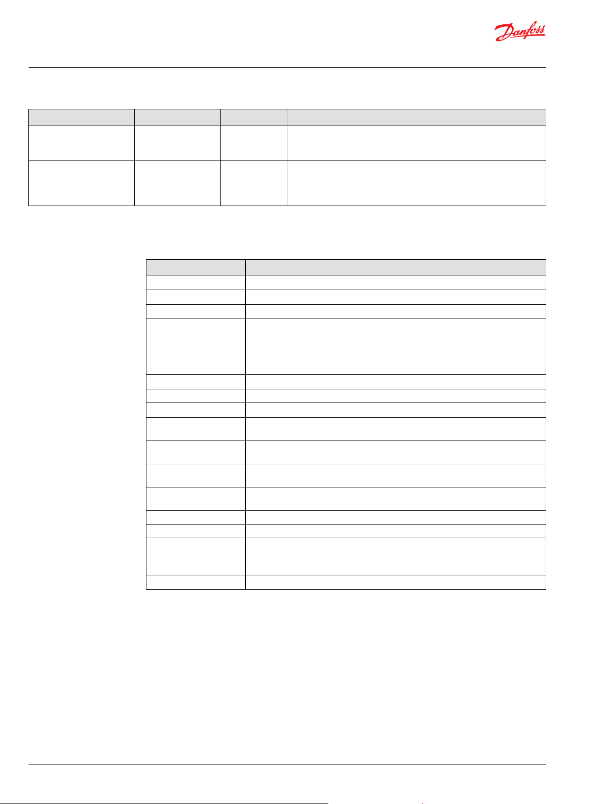
Revision history Table of revisions
Date Changed Rev
October 2020 First edition 0101
2 | © Danfoss | October 2020 AQ339983296573en-000101
Page 3

User Manual
PLUS+1® Function Block Library—UART
Contents
Library Introduction
Before You Begin
Limitations.......................................................................................................................................................................................... 5
Setting up UART for Transmission and Reception................................................................................................................6
Set up Transmission................................................................................................................................................................... 6
Set up Reception......................................................................................................................................................................... 8
Setting up UART with Heartbeat Messages............................................................................................................................9
Heartbeat Transmission......................................................................................................................................................... 10
Heartbeat Reception............................................................................................................................................................... 10
UART_Rx_Buffer
Inputs..................................................................................................................................................................................................12
Outputs..............................................................................................................................................................................................12
IEC 61508-3 Annex D Supplemental Information.............................................................................................................. 13
UART_Rx_Hrtbeat
Outputs..............................................................................................................................................................................................14
IEC 61508-3 Annex D Supplemental Information.............................................................................................................. 15
UART_Rx_Msg
Inputs..................................................................................................................................................................................................17
Outputs..............................................................................................................................................................................................17
IEC 61508-3 Annex D Supplemental Information.............................................................................................................. 18
UART_Tx_Buffer
Inputs..................................................................................................................................................................................................19
Outputs..............................................................................................................................................................................................19
IEC 61508-3 Annex D Supplemental Information.............................................................................................................. 20
UART_Tx_Hrtbeat
Outputs..............................................................................................................................................................................................21
IEC 61508-3 Annex D Supplemental Information.............................................................................................................. 22
UART_Tx_Msg
Inputs .................................................................................................................................................................................................23
Outputs..............................................................................................................................................................................................23
IEC 61508-3 Annex D Supplemental Information.............................................................................................................. 24
©
Danfoss | October 2020 AQ339983296573en-000101 | 3
Page 4

User Manual
PLUS+1® Function Block Library—UART
Library Introduction
The UART function blocks in this library help enable communication over a universal asynchronous
receiver-transmitter.
The UART library contains function blocks which ensure the exact information sent is the exact
information received.
4 | © Danfoss | October 2020 AQ339983296573en-000101
Page 5
User Manual
PLUS+1® Function Block Library—UART
Before You Begin
Before you use the library, note the following:
•
SC0XX-1XX devices are supported for use with the library.
•
SC0XX-0XX devices are not supported for use with the library.
•
MCXXX-0XX, MCXXX-1XX and Display devices are not supported by the library.
•
Minimum required SC0XX-1XX HWD version is v210.
•
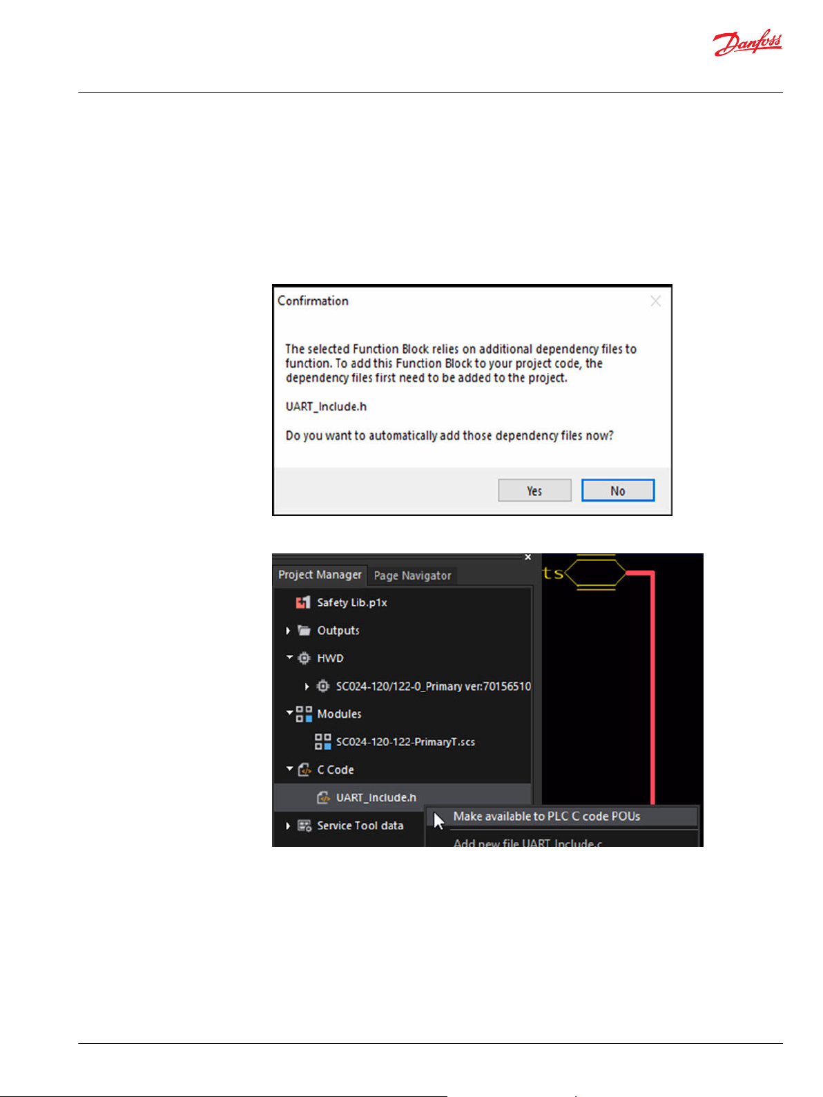
Make dependency files available, as follows:
1. After you add the first UART function block to the application, click Yes in the dialog box that
appears.
Limitations
2. In the project manager, right click on UART_Include.h and select Make available to PLC C code
POUs.
Before using the function blocks in this library, note the following limitations of some blocks.
A UART_Tx_Msg block can only transmit every other loop. If a piece of data needs to be sent every loop,
ensure it uses two blocks with two different IDs with alternating transmission.
The UART_Tx_Buffer block can send up to four messages per loop. Any additional messages stored in
the buffer are sent in the following loop following a First In, First Out queue. The buffer can hold 18
messages from the UART_Tx_Msg block.
©
Danfoss | October 2020 AQ339983296573en-000101 | 5
Page 6
User Manual
PLUS+1® Function Block Library—UART
Before You Begin
Setting up UART for Transmission and Reception
Set up UART so an application can transmit messages and an application can receive messages.
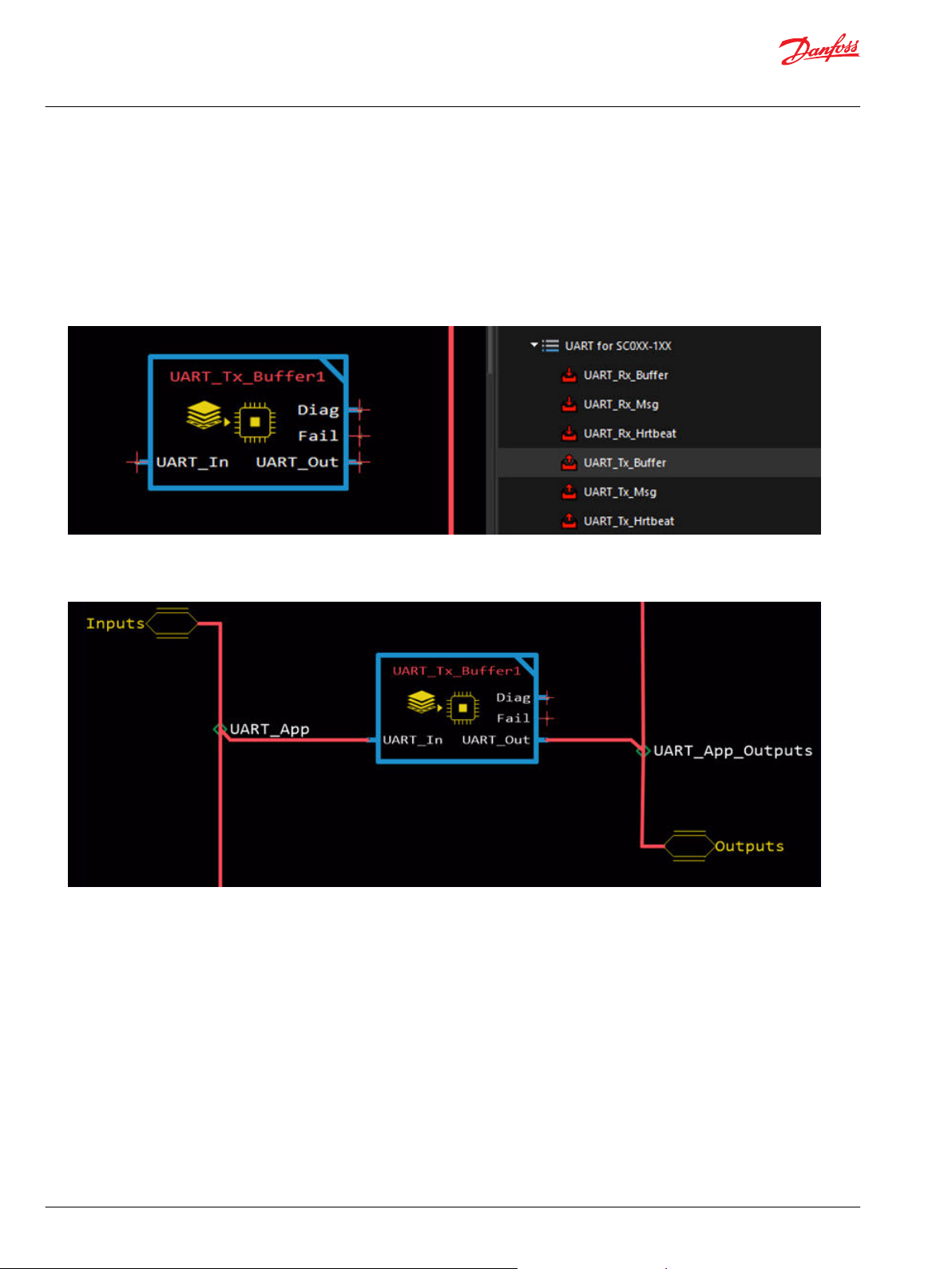
Set up Transmission
To set up an application to transmit messages, complete the tasks that follow.
1. From the Library, drag in the UART_Tx_Buffer block. Place this function near the end of the
application.
2. Connect the UART_In bus to the UART_App bus from the Inputs bus of the controller template.
Then, connect the UART_Out bus to the UART_App_Outputs bus from the Outputs bus of the
controller template.
6 | © Danfoss | October 2020 AQ339983296573en-000101
Page 7
User Manual
PLUS+1® Function Block Library—UART
Before You Begin
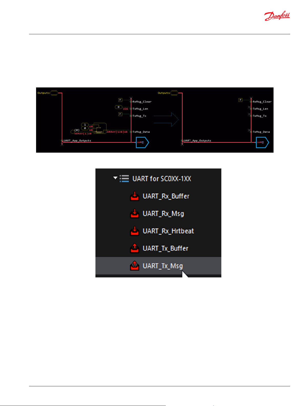
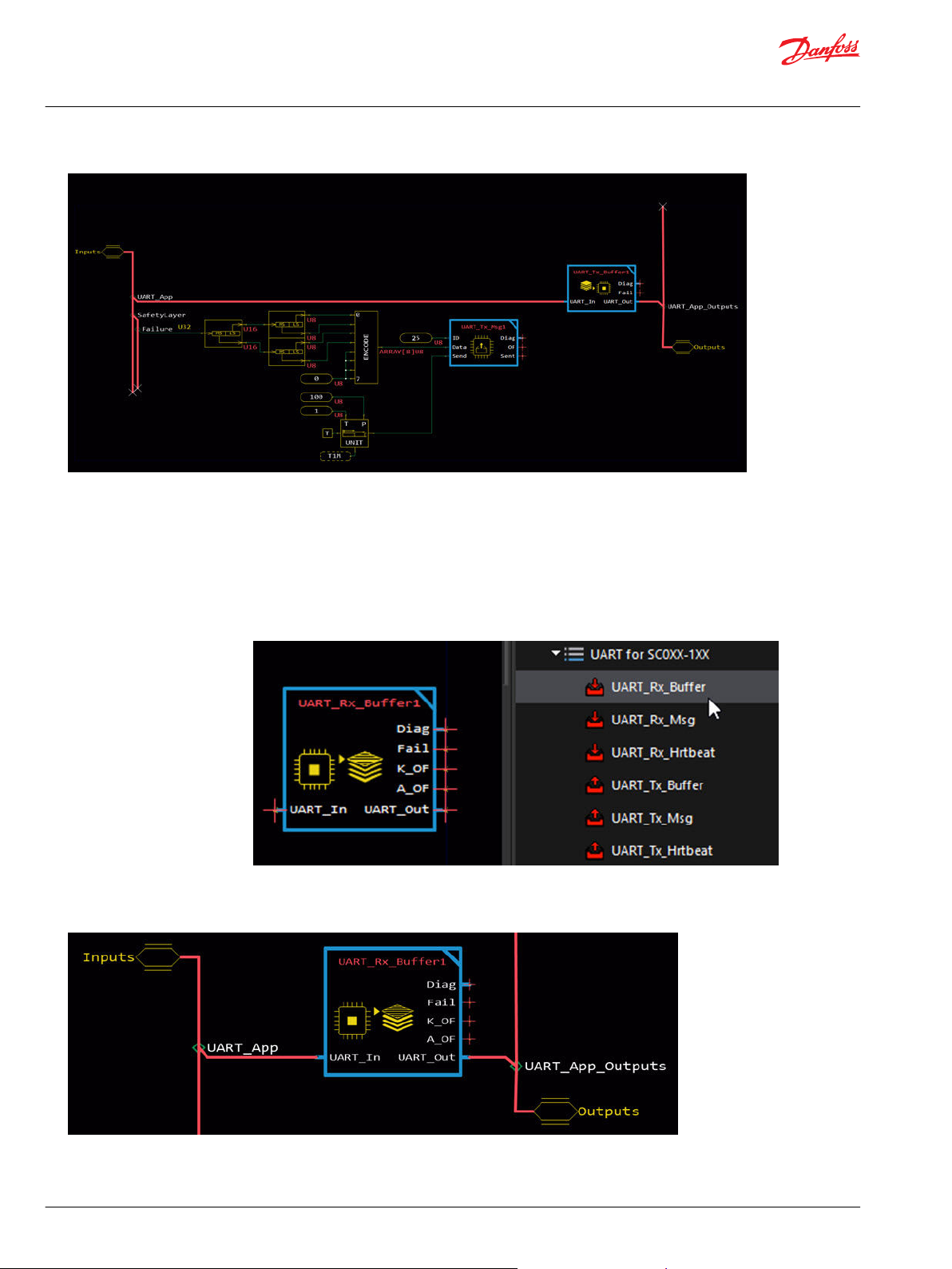
3. Navigate to the UART page in the outputs section of the controller template, “!TOP!Outputs!UART.”
Remove the logic from the following signals for proper compilation: TxMsg_Len, TxMsg_Tx, and
TxMsg_Data.
Make the changes shown in the following figure. If you are using the UART_Rx_Buffer block, also
•
remove the signal mentioned in the next section.
4. Add a UART_Tx_Msg block. This block is used to send 8 bytes of data over UART. The messages are
added to a queue that is processed by the UART_Tx_Buffer.
5. Connect inputs to the block, as shown in the following example.
ID: 25. Values from 0 to 120 are allowed.
•
Data: Safety Layer Failure signal in the lower four bytes, zero in the upper four bytes.
•
Send: Sent every 100 ms via oscillator.
•
©
Danfoss | October 2020 AQ339983296573en-000101 | 7
Page 8
User Manual
PLUS+1® Function Block Library—UART
Before You Begin
In the example, the message is then sent every 100 ms. To set up the other application to receive the
message, see Set up Reception.
Set up Reception
To set up an application to receive messages, complete the tasks that follow.
1. From the Library, drag in the UART_Rx_Buffer block. Place this function near the front of the
application.
2. Connect the UART_In bus to the UART_App bus from the Inputs bus of the controller template.
Then, connect the UART_Out bus to the UART_App_Outputs bus from the Outputs bus of the
controller template.
8 | © Danfoss | October 2020 AQ339983296573en-000101
Page 9

User Manual
PLUS+1® Function Block Library—UART
Before You Begin
3. Navigate to the UART page in the outputs section of the controller template, “!TOP!Outputs!UART.”
Remove the logic from the following signal for proper compilation: RxMsg_Clear
Make the changes as shown in the following figure. If you are using the UART_Tx_Buffer block, you
also remove the signals mentioned in the topic Set up Transmission.
4. Add a UART_Rx_Msg block. This block is used to receive 8 bytes of data over UART. The messages are
processed from a queue that is managed by the UART_Rx_Buffer.
5. Connect the block to input, as the following example shows. Get an output signal that was sent over
UART.
ID: 15, Values from 0 to 120 are allowed. In the previous section’s example, the “UART_Tx_Msg”
•
block was setup to transmit using an ID of 15.
Data: Safety Layer Failure signal in the lower four bytes, zero in the upper four bytes. This is the
•
signal that was transmitted using the UART_Tx_Msg from the previous section.
Setting up UART with Heartbeat Messages
Set up UART so that heartbeat messages can be transmitted and received.
©
Danfoss | October 2020 AQ339983296573en-000101 | 9
Page 10

User Manual
PLUS+1® Function Block Library—UART
Before You Begin
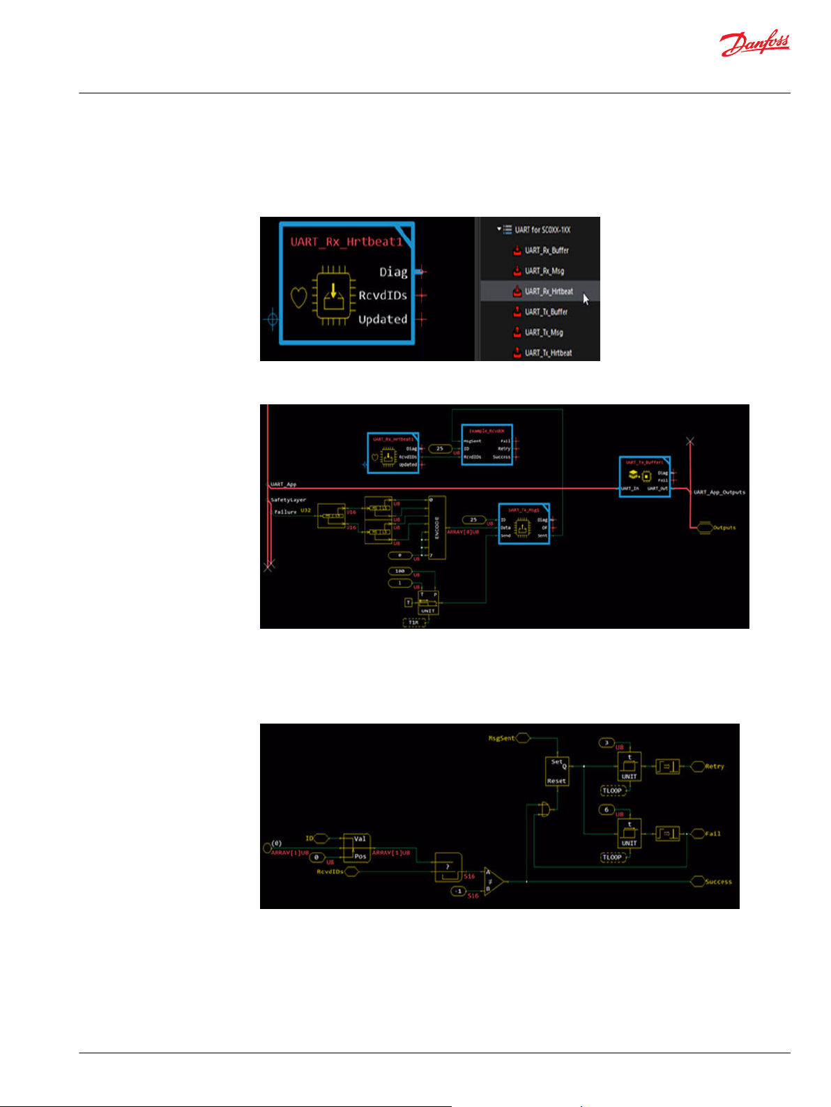
Heartbeat Transmission
The UART_Tx_Hrtbeat block handles the packetization of successfully received IDs.
This message is sent every other loop, automatically alternating between ID 121 and 122. A
UART_Rx_Hrtbeat block placed in the other application receives the message.
1. From the Library, drag in the UART_Tx_Hrtbeat block.
Place this function after any UART_Rx_Msg blocks.
•
It is recommend to place the function before any UART_Tx_Msg blocks.
•
2. The following example shows a UART_Tx_Hrtbeat block in an application. Note how it is after any
UART_Rx_Msg blocks and before any UART_Tx_Msg blocks. The example that follows shows how,
when a message with ID 15 is received, it is added to a Heartbeat message to transmit back to the
other processor.
Heartbeat Reception
The UART_Rx_Hrtbeat block receives a heartbeat message from the other application.
It contains an array of successfully received IDs. The message is sent every other loop by the other
processor via UART_Tx_Hrtbeat. Due to the asynchronous nature of the processors and the
communication method, 0, 1, or 2 messages could be received in a single loop.
10 | © Danfoss | October 2020 AQ339983296573en-000101
Page 11
User Manual
PLUS+1® Function Block Library—UART
Before You Begin
1. From the Library, drag in the UART_Rx_Hrtbeat block.
Place this function after the UART_Rx_Buffer block.
•
It is recommend to be placed before any UART_Tx_Msg blocks.
•
2. To determine if a sent message was properly received, you can monitor the RcvdIDs signal and use
the Find Array component to look for the ID. An example follows.
3. Inside the Example_RcvdOK block, you can use a section of logic to search for a certain ID.
When a message is sent, it sets the Set/Reset Latch component true, which starts two counters.
•
If the message ID does not appear in the RcvdIDs array, then they eventually pulse true.
•
Otherwise, if the ID does appear in the RcvdIDs array, the Success signal goes true.
•
©
Danfoss | October 2020 AQ339983296573en-000101 | 11
Page 12

User Manual
PLUS+1® Function Block Library—UART
UART_Rx_Buffer
The UART_Rx_Buffer function block receives data transmitted over the UART connection.
The received data is placed in a common buffer that the UART_Rx_Buffer message blocks use.
Place the UART_Rx_Buffer function block at the front of the application.
Inputs
Inputs to the UART_Rx_Buffer function block are described.
Item Type Range Description [Unit]
SL_Failure U32 —— Reports safety layer failures.
UART_In BUS —— Connect to the UART_App sub-bus if using the Main template.
RxMsg_Rx BOOL T/F T: Data was received during the last processing loop.
F: No new data was received.
RxMsg_Len U16 —— Length of the received message since the buffer was last cleared.
You can find this variable in the UART_App sub-bus if using the Main template.
RxMsg_Data (ARRAY[128]U8) —— Data buffer for UART reception.
You can find this variable in the UART_App sub-bus if using the Main template.
Outputs
Outputs of the UART_Rx_Buffer function block are described.
Item Type Range Description [Unit]
Diag BUS —— This bus provides diagnostic values for troubleshooting.
All output signals are in the bus.
CodeVer U16 0-65535 Displays the version of the code implementation.
[0.01]
Buffer_Length U8 0-255 Current amount of data in the buffer after processing kernel UART data.
12 | © Danfoss | October 2020 AQ339983296573en-000101
Page 13

User Manual
PLUS+1® Function Block Library—UART
UART_Rx_Buffer
Item Type Range Description [Unit]
Fail U8 0-3 Bitwise code where multiple items can be reported at a time.
0x00: OK.
0x01: A UART_Rx_Msg block executed before the UART_Rx_Buffer block.
0x02: ExecTime of Primary differs from Secondary. Expect communication issues to arise.
K_Overflow BOOL T/F Signal that indicates if an overflow occurred in the lower level kernel buffer.
T: An overflow occurred. Data was lost.
F: No overflow occurred.
A_Overflow BOOL T/F Signal that indicates if an overflow occurred in the local application buffer.
T: An overflow occurred. Data was lost.
F: No overflow occurred.
UART_Out BUS —— Connect to the UART_App_Outputs sub-bus if using the Main template.
RxMsg_Clear BOOL T/F Signal used to clear the receive buffer.
You can find this variable in the UART_App_Outputs sub-bus if using the Main template.
*Disconnect on Outputs_UART page.
T: Clear buffer.
F: Do not clear input buffer.
IEC 61508-3 Annex D Supplemental Information
The following table provides IEC 61508-3 Annex D supplemental information.
Label Description
Software Name
Software Version
Release Status Released.
Required Knowledge
Revision History
Known Issues Not applicable.
Backward Compatibility
Market Requirements Not
Met
Change Request Direct any change request to the PLUS+1® help desk:
Support Direct any request to the PLUS+1® help desk:
OS The software only runs on SCXXX-1XX series hardware with minimum HWD version
Tool Requirements PLUS+1® GUIDE version 10.1 or later certified version.
Security Not applicable.
Design Level
Certification Not certified.
UART_Rx_Buffer
2.10
1. The programmer must fully read and understand all parts of the Safety Manual
before attempting to use the software product.
2. The programmer must have well-founded knowledge about using PLUS+1® tools.
3. The programmer must fully read and understand all parts of the Safety Library—
User Manual before attempting to use the software product.
2.10. First release of function.
——
——
plus1helpdesk@danfoss.com
plus1helpdesk@danfoss.com
210.
All software development has been done using SIL2 processes.
•
The hardware library is not SIL2 certified.
•
Danfoss provides required documentation to certifying bodies on customer request.
•
©
Danfoss | October 2020 AQ339983296573en-000101 | 13
Page 14

User Manual
PLUS+1® Function Block Library—UART
UART_Rx_Hrtbeat
The UART_Rx_Hrtbeat function block receives a heartbeat message over the UART connection.
This function block unpacks successfully received IDs.
You must place this function block after the UART_Rx_Buffer function block.
The heartbeat contains information about what messages were properly received by the other processor.
The function block receives ID 121 and 122, messages that alternate in reception. However, it is possible
that both might be received during the same loop.
Input data types must exactly match the indicated type to successfully compile.
Outputs
Outputs of the UART_Rx_Hrtbeat function block are described.
Item Type Range Description [Unit]
Diag BUS —— This bus provides diagnostic values for troubleshooting.
All output signals are in the bus.
Heartbeat_A BUS —— Bus containing signals related to the heartbeat with ID 121.
Err BUS —— Contains the errors detected by the function block.
CRC_Mismatch BOOL T/F Indicates if the received CRC does not match the calculated CRC.
T: CRC mismatch.
F: CRC OK.
SeqNum_Mismatch BOOL T/F Indicates if the received sequence number does not match the calculated
sequence number.
T: Sequence Number mismatch.
F: Sequence Number OK.
Data (ARRAY[8]U8) —— The data received.
Updated BOOL T/F True when new data is available.
T: Received new data.
F: Did not receive new data.
MsgFound BOOL T/F True when a matching message is found.
T: Found a message matching the defined ID.
F: Did not find a message.
CalcCRC U8 0-255 The CRC calculated by the receiver based on the data received.
RcvCRC U8 0-255 The CRC from the received message.
14 | © Danfoss | October 2020 AQ339983296573en-000101
Page 15
User Manual
PLUS+1® Function Block Library—UART
UART_Rx_Hrtbeat
Item Type Range Description [Unit]
CalcSeqNum U8 0-31 The Sequence Number calculated by the receiver.
RcvSeqNum U8 0-31 The Sequence Number from the received message.
Heartbeat_B BUS —— Bus containing signals related to the heartbeat with ID 122.
Err BUS —— Contains the errors detected by the function block.
CRC_Mismatch BOOL T/F Indicates if the received CRC does not match the calculated CRC.
T: CRC mismatch.
F: CRC OK.
SeqNum_Mismatch BOOL T/F Indicates if the received sequence number does not match the calculated
sequence number.
T: Sequence Number mismatch.
F: Sequence Number OK.
Data (ARRAY[8]U8) —— The data received.
Updated BOOL T/F True when new data is available.
T: Received new data.
F: Did not receive new data.
MsgFound BOOL T/F True when a matching message is found.
T: Found a message matching the defined ID.
F: Did not find a message.
CalcCRC U8 0-255 The CRC calculated by the receiver based on the data received.
RcvCRC U8 0-31 The Sequence Number from the received message.
CalcSeqNum U8 0-31 The sequence number calculated by the receiver.
RcvSeqNum U8 0-255 The CRC from the received message.
RcvdIDs (ARRAY[16]U8) —— Contains the IDs that were successfully received by the other application.
Monitor this signal to determine if messages sent from this application were
received by the other application.
Updated BOOL T/F True when new data is available.
T: Received new data.
F: Did not receive new data.
IEC 61508-3 Annex D Supplemental Information
The following table provides IEC 61508-3 Annex D supplemental information.
Label Description
Software Name
Software Version
Release Status Released.
Required Knowledge
Revision History
Known Issues Not applicable.
Backward Compatibility
Market Requirements Not
Met
Change Request Direct any change request to the PLUS+1® help desk:
©
Danfoss | October 2020 AQ339983296573en-000101 | 15
Description
UART_Rx_Hrtbeat
2.10
1. The programmer must fully read and understand all parts of the Safety Manual
before attempting to use the software product.
2. The programmer must have well-founded knowledge about using PLUS+1® tools.
3. The programmer must fully read and understand all parts of the Safety Library—
User Manual before attempting to use the software product.
2.10. First release of function.
——
——
plus1helpdesk@danfoss.com
Page 16

User Manual
PLUS+1® Function Block Library—UART
UART_Rx_Hrtbeat
Label Description
Support Direct any request to the PLUS+1® help desk:
OS The software only runs on SCXXX-1XX series hardware with minimum HWD version
Tool Requirements PLUS+1® GUIDE version 10.1 or later certified version.
Security Not applicable.
Design Level
Certification Not certified.
Description
plus1helpdesk@danfoss.com
210.
All software development has been done using SIL2 processes.
•
The hardware library is not SIL2 certified.
•
Danfoss provides required documentation to certifying bodies on customer request.
•
16 | © Danfoss | October 2020 AQ339983296573en-000101
Page 17
User Manual
PLUS+1® Function Block Library—UART
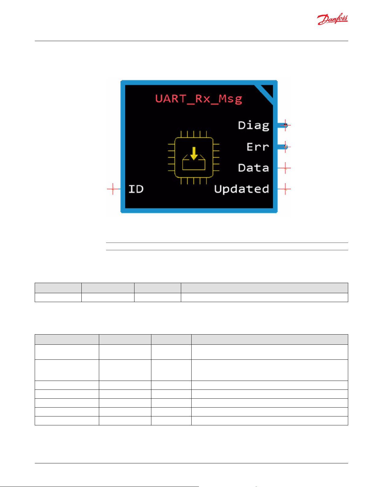
UART_Rx_Msg
The UART_Rx_Msg function block receives a message over the UART connection.
This function block handles the unpacking of the data. It receives the message based on ID.
Place the UART_Rx_Msg function block after the UART_Rx_Buffer function block.
Input data types must exactly match the indicated type to successfully compile.
Inputs
Inputs to the UART_ Rx_Msg function block are described.
Item Type Range Description [Unit]
ID U8 0-120 A unique identifier for the message being received.
Outputs
Outputs of the UART_Rx_Msg function block are described.
Item Type Range Description [Unit]
Diag BUS —— This bus provides diagnostic values for troubleshooting.
All output signals are in the bus.
MsgFound BOOL T/F True when a matching message is found.
T: Found a message matching the defined ID.
F: Did not find a message.
CalcCRC U8 0-255 The CRC calculated by the receiver based on the data received.
RcvCRC U8 0-255 The CRC from the received message.
CalcSeqNum U8 0-31 The sequence number calculated by the receiver.
RcvSeqNum U8 0-31
Err BUS —— Contains the errors that the function block detects.
The sequence number from the received message.
©
Danfoss | October 2020 AQ339983296573en-000101 | 17
Page 18
User Manual
PLUS+1® Function Block Library—UART
UART_Rx_Msg
Item Type Range Description [Unit]
CRC_Mismatch BOOL T/F Indicates if the received CRC does not match the calculated CRC.
T: CRC mismatch.
F: CRC OK.
SeqNum_Mismatch BOOL T/F Indicates if the received sequence number does not match the calculated
sequence number.
T: Sequence number mismatch.
F: Sequence number OK.
IEC 61508-3 Annex D Supplemental Information
The following table provides IEC 61508-3 Annex D supplemental information.
Label Description
Software Name
Software Version
Release Status Released.
Required Knowledge
Revision History
Known Issues Not applicable.
Backward Compatibility
Market Requirements Not
Met
Change Request Direct any change request to the PLUS+1® help desk:
Support Direct any request to the PLUS+1® help desk:
OS The software only runs on SCXXX-1XX series hardware with minimum HWD version
Tool Requirements PLUS+1® GUIDE version 10.1 or later certified version.
Security Not applicable.
Design Level
Certification Not certified.
UART_Rx_Msg
2.10
1. The programmer must fully read and understand all parts of the Safety Manual
before attempting to use the software product.
2. The programmer must have well-founded knowledge about using PLUS+1® tools.
3. The programmer must fully read and understand all parts of the Safety Library—
User Manual before attempting to use the software product.
2.10. First release of function.
——
——
plus1helpdesk@danfoss.com
plus1helpdesk@danfoss.com
210.
All software development has been done using SIL2 processes.
•
The hardware library is not SIL2 certified.
•
Danfoss provides required documentation to certifying bodies on customer request.
•
18 | © Danfoss | October 2020 AQ339983296573en-000101
Page 19

User Manual
PLUS+1® Function Block Library—UART
UART_Tx_Buffer
The UART_Tx_Buffer function block places data in the UART transmission buffer.
This function block transmits messages over the UART connection.
Place the function block at the rear of the application.
Inputs
Inputs to the UART_Tx_Buffer function block are described.
Item Type Range Description [Unit]
SafetyLayer.Failure U32 —— Reports safety layer failures.
UART_In BUS —— Connect to the UART_App sub-bus if using the Main template.
TxMsg_Rdy BOOL T/F You can find this variable in the UART_App sub-bus if using the Main template.
T: No ongoing transmission.
F: Message transmission ongoing.
TxMsg_Tx BOOL T/F You can find this variable in the UART_App sub-bus if using the Main template.
T: Message is queued for transmission.
F: Data sent. No ongoing transmission.
Outputs
Outputs of the UART_Tx_Buffer function block are described.
Item Type Range Description [Unit]
Diag BUS —— This bus provides diagnostic values for troubleshooting.
CodeVer U16 0-65535 Displays the version of the code implementation.
[0.01]
Buffer_Length U8 0-255 Current amount of data in the buffer after processing application UART data.
Fail
UART_Out BUS —— Connect to the UART_App_Outputs sub-bus if using the Main template.
U8 0-3 Bitwise code where multiple items can be reported at a time.
0x00: OK.
0x02: ExecTime of Primary differs from Secondary. Expect communication issues
to arise.
©
Danfoss | October 2020 AQ339983296573en-000101 | 19
Page 20

User Manual
PLUS+1® Function Block Library—UART
UART_Tx_Buffer
Item Type Range Description [Unit]
TxMsg_Data (ARRAY[128]U8) —— Data buffer for UART transmission.
You can find this variable in the UART_App_Outputs sub-bus if using the Main
template.
*Disconnect on Outputs_UART page.
Tx_Msg_Len U16 —— Length of the message transmission.
You can find this variable in the UART_App_Outputs sub-bus if using the Main
template.
*Disconnect on Outputs_UART page.
TxMsg_Tx BOOL T/F You can find this variable in the UART_App_Outputs sub-bus if using the Main
template.
*Disconnect on Outputs_UART page.
Cleared when data is sent.
T: Message is queued for transmission.
F: Data sent. No ongoing transmission.
IEC 61508-3 Annex D Supplemental Information
The following table provides IEC 61508-3 Annex D supplemental information.
Label Description
Software Name
Software Version
Release Status Released.
Required Knowledge
Revision History
Known Issues Not applicable.
Backward Compatibility
Market Requirements Not
Met
Change Request Direct any change request to the PLUS+1® help desk:
Support Direct any request to the PLUS+1® help desk:
OS The software only runs on SCXXX-1XX series hardware with minimum HWD version
Tool Requirements PLUS+1® GUIDE version 10.1 or later certified version.
Security Not applicable.
Design Level
Certification Not certified.
UART_Tx_Buffer
2.10
1. The programmer must fully read and understand all parts of the Safety Manual
before attempting to use the software product.
2. The programmer must have well-founded knowledge about using PLUS+1® tools.
3. The programmer must fully read and understand all parts of the Safety Library—
User Manual before attempting to use the software product.
2.10. First release of function.
——
——
plus1helpdesk@danfoss.com
plus1helpdesk@danfoss.com
210.
All software development has been done using SIL2 processes.
•
The hardware library is not SIL2 certified.
•
Danfoss provides required documentation to certifying bodies on customer request.
•
20 | © Danfoss | October 2020 AQ339983296573en-000101
Page 21

User Manual
PLUS+1® Function Block Library—UART
UART_Tx_Hrtbeat
The UART_Tx_Hrtbeat function block transmits a heartbeat message over the UART connection.
The function block creates packets for successfully received IDs. The UART_Rx_Hrtbeat function block
receives the message of the UART_Tx_Hrtbeat function block, to provide feedback of a properly
received message.
The function block alternates between ID 121 and 122, to transmit every other loop.
Input data types must exactly match the indicated type to successfully compile.
You must place the UART_Tx_Hrtbeat function block:
•
After the UART_Rx_Msg function blocks.
•
Before the UART_Tx_Buffer function block.
It is recommended you place the UART_Tx_Hrtbeat function block before any UART_Tx_Msg function
blocks.
Outputs
Outputs of the UART_Tx_Hrtbeat function block are described.
Item Type Range Description [Unit]
Diag BUS —— This bus provides diagnostic values for troubleshooting.
All output signals are in the bus.
Heartbeat_A BUS —— Bus containing signals related to the heartbeat with ID 121.
Sent BOOL T/F True when the message is added to the buffer.
T: Message is added to the buffer.
F: No action.
CalcCRC U8 0-255 The CRC calculated by the function block based on the data being sent.
CalcSeqNum U8 0-31 The Sequence Number calculated by the function block.
Heartbeat_B BUS —— Bus containing signals related to the heartbeat with ID 122.
Sent BOOL T/F True when the message is added to the buffer.
T: Message is added to the buffer.
F: No action.
CalcCRC U8 0-255 The CRC calculated by the function block based on the data being sent.
CalcSeqNum U8 0-31 The Sequence Number calculated by the function block.
Heartbeat_B BUS —— Bus containing signals related to the heartbeat with ID 121.
©
Danfoss | October 2020 AQ339983296573en-000101 | 21
Page 22

User Manual
PLUS+1® Function Block Library—UART
UART_Tx_Hrtbeat
Item Type Range Description [Unit]
Sent BOOL T/F True when the message is added to the buffer.
T: Message is added to the buffer.
F: No action.
CalcCRC U8 0-255 The CRC calculated by the function block based on the data being sent.
CalcSeqNum U8 0-31 The Sequence Number calculated by the function block.
Heartbeat_B BUS —— Bus containing signals related to the heartbeat with ID 122.
Sent BOOL T/F True when the message is added to the buffer.
T: Message is added to the buffer.
F: No action.
CalcCRC U8 0-255 The CRC calculated by the function block based on the data being sent.
CalcSeqNum U8 0-31 The Sequence Number calculated by the function block.
Overflow BOOL T/F Indicates if there is room available in the buffer for the heartbeat message.
T: No space.
F: Space is available.
Sent BOOL T/F Indicates if a message is added to the buffer.
T: Message is added to the buffer.
F: No action.
IEC 61508-3 Annex D Supplemental Information
The following table provides IEC 61508-3 Annex D supplemental information.
Label Description
Software Name
Software Version
Release Status Released.
Required Knowledge
Revision History
Known Issues Not applicable.
Backward Compatibility
Market Requirements Not
Met
Change Request Direct any change request to the PLUS+1® help desk:
Support Direct any request to the PLUS+1® help desk:
OS The software only runs on SCXXX-1XX series hardware with minimum HWD version
Tool Requirements PLUS+1® GUIDE version 10.1 or later certified version.
Security Not applicable.
Design Level
Certification Not certified.
UART_Tx_Hrtbeat
2.10
1. The programmer must fully read and understand all parts of the Safety Manual
before attempting to use the software product.
2. The programmer must have well-founded knowledge about using PLUS+1® tools.
3. The programmer must fully read and understand all parts of the Safety Library—
User Manual before attempting to use the software product.
2.10. First release of function.
——
——
plus1helpdesk@danfoss.com
plus1helpdesk@danfoss.com
210.
All software development has been done using SIL2 processes.
•
The hardware library is not SIL2 certified.
•
Danfoss provides required documentation to certifying bodies on customer request.
•
22 | © Danfoss | October 2020 AQ339983296573en-000101
Page 23

User Manual
PLUS+1® Function Block Library—UART
UART_Tx_Msg
The UART_Tx_Msg function block transmits a message over the UART connection.
It creates packets for the data and places the data in a form that the UART_Rx_Msg function block can
interpret.
Inputs
Inputs to the UART_Tx_Msg function block are described.
Item Type Range Description [Unit]
ID U8 0-120 Used as a unique identifier for the message being transmitted.
Data (ARRAY[8]U8) ——
Send BOOL T/F On positive transition, Send adds the message to the buffer if there is room
The data to be sent.
available. If Overflow is true, the message was not added to the transmission
buffer.
T: Add message to transmission buffer.
F: Do not add message to buffer.
Outputs
Outputs of the UART_Tx_Msg function block are described.
Item Type Range Description [Unit]
Diag BUS —— This bus provides diagnostic values for troubleshooting.
All output signals are in the bus.
CalcCRC U8 0-255 The CRC calculated by the function block based on the data being sent.
CalcSeqNum U8 0-31 The Sequence Number calculated by the function block.
Overflow BOOL T/F True, if no room is available in the buffer while Send is true.
T: No space.
F: Space is available.
Sent BOOL T/F Indicates if a message is added to the buffer.
T: Message is added to the buffer.
F: No action.
©
Danfoss | October 2020 AQ339983296573en-000101 | 23
Page 24

User Manual
PLUS+1® Function Block Library—UART
UART_Tx_Msg
IEC 61508-3 Annex D Supplemental Information
The following table provides IEC 61508-3 Annex D supplemental information.
Label Description
Software Name
Software Version
Release Status Released.
Required Knowledge
Revision History
Known Issues Not applicable.
Backward Compatibility
Market Requirements Not
Met
Change Request Direct any change request to the PLUS+1® help desk:
Support Direct any request to the PLUS+1® help desk:
OS The software only runs on SCXXX-1XX series hardware with minimum HWD version
Tool Requirements PLUS+1® GUIDE version 10.1 or later certified version.
Security Not applicable.
Design Level
Certification Not certified.
UART_Tx_Msg
2.10
1. The programmer must fully read and understand all parts of the Safety Manual
before attempting to use the software product.
2. The programmer must have well-founded knowledge about using PLUS+1® tools.
3. The programmer must fully read and understand all parts of the Safety Library—
User Manual before attempting to use the software product.
2.10. First release of function.
——
——
plus1helpdesk@danfoss.com
plus1helpdesk@danfoss.com
210.
All software development has been done using SIL2 processes.
•
The hardware library is not SIL2 certified.
•
Danfoss provides required documentation to certifying bodies on customer request.
•
24 | © Danfoss | October 2020 AQ339983296573en-000101
Page 25

Danfoss
Power Solutions GmbH & Co. OHG
Krokamp 35
D-24539 Neumünster, Germany
Phone: +49 4321 871 0
Danfoss
Power Solutions ApS
Nordborgvej 81
DK-6430 Nordborg, Denmark
Phone: +45 7488 2222
Danfoss
Power Solutions (US) Company
2800 East 13th Street
Ames, IA 50010, USA
Phone: +1 515 239 6000
Danfoss
Power Solutions Trading
(Shanghai) Co., Ltd.
Building #22, No. 1000 Jin Hai Rd
Jin Qiao, Pudong New District
Shanghai, China 201206
Phone: +86 21 2080 6201
Products we offer:
Hydro-Gear
www.hydro-gear.com
Daikin-Sauer-Danfoss
www.daikin-sauer-danfoss.com
Cartridge valves
•
DCV directional control
•
valves
Electric converters
•
Electric machines
•
Electric motors
•
Gear motors
•
Gear pumps
•
Hydraulic integrated
•
circuits (HICs)
Hydrostatic motors
•
Hydrostatic pumps
•
Orbital motors
•
PLUS+1® controllers
•
PLUS+1® displays
•
PLUS+1® joysticks and
•
pedals
PLUS+1® operator
•
interfaces
PLUS+1® sensors
•
PLUS+1® software
•
PLUS+1® software services,
•
support and training
Position controls and
•
sensors
PVG proportional valves
•
Steering components and
•
systems
Telematics
•
Danfoss Power Solutions is a global manufacturer and supplier of high-quality hydraulic and
electric components. We specialize in providing state-of-the-art technology and solutions
that excel in the harsh operating conditions of the mobile off-highway market as well as the
marine sector. Building on our extensive applications expertise, we work closely with you to
ensure exceptional performance for a broad range of applications. We help you and other
customers around the world speed up system development, reduce costs and bring vehicles
and vessels to market faster.
Danfoss Power Solutions – your strongest partner in mobile hydraulics and mobile
electrification.
Go to www.danfoss.com for further product information.
We offer you expert worldwide support for ensuring the best possible solutions for
outstanding performance. And with an extensive network of Global Service Partners, we also
provide you with comprehensive global service for all of our components.
Local address:
Danfoss can accept no responsibility for possible errors in catalogues, brochures and other printed material. Danfoss reserves the right to alter its products without notice. This also applies to products
already on order provided that such alterations can be made without subsequent changes being necessary in specifications already agreed.
All trademarks in this material are property of the respective companies. Danfoss and the Danfoss logotype are trademarks of Danfoss A/S. All rights reserved.
©
Danfoss | October 2020 AQ339983296573en-000101
 Loading...