

Page 1
TP7001 Range
Electronic 7 Day
Programmable Room Thermostat
Danfoss Heating
Installation Guide
Page 2

For a large print version of these instructions
please call Marketing on 0845 121 7400.
®
Certification Mark
Danfoss can accept no responsibility for possible errors in catalogues, brochures, and other
printed material. All trademarks in this material are property of the respective companies.
Danfoss and the Danfoss logotype are trademarks of Danfoss A/S. All rights reserved.
2
TP7001
Page 3
Installation Instructions
TP7001 Range
Electronic Programmable Room Thermostat
Index
GB
GB
1.0 Installation Guide ................................................................................4
2.0 System Overview .................................................................................4
3.0 Installation ..............................................................................................5
3.1 Removing the wallplate .............................................................5
3.2 Installation considerations ........................................................5
3.3 A xing the backplate .................................................................5
3.4 Wiring ...............................................................................................6
3.5 Batteries ...........................................................................................6
3.6 Tamperproof operation ..............................................................7
3.7 Mounting the unit ........................................................................7
3.8 Unit startup .....................................................................................7
4.0 Installer Advanced Programming Options .............................7
4.1 Service Interval Timer .................................................................7
4.2 Entering Installer Advanced Programming ........................8
5.0 Reset Procedure ................................................................................17
5.1 Partial Reset ................................................................................. 17
5.2 User Reset ..................................................................................... 17
5.3 Installer Reset .............................................................................. 17
Danfoss Heating
3
Page 4
1.0 Installation Guide
Please Note:
This product should only be installed by a quali ed electrician or
competent heating installer and should be in accordance with the
GB
GB
current edition of the IEEE wiring regulations.
2.0 System Overview
Thermostat Features TP7001 TP7001M
Power supply
Memory backup Retained for the life of the product
Factory set calendar clock Automatic summer/winter time change
Switching action of output relay 1 x SPDT, Type 1B
Switch rating of relay contact 3(1) A, 10-230 Volts
Remote sensor inputs
2 x AA/MN1500/LR6
230V ± 15% 50Hz
alkaline batteries
Up to three remote sensors, which can be
set by the installer for remote temperature
sensor, limit sensor, outdoor sensor, window
contact or telephone activated switch
contacts
Rated Impulse Voltage 2.5 kV
Dimensions (mm) 140 wide x 91 high x 28 deep
Ball Pressure Test 75°C
Temperature Range 5-30°C
Design Standard EN 60730-2-7
Control Pollution Situation Degree 2
Time accuracy ± 1 minute per month
Temperature accuracy ±1°C
4
TP7001
Page 5
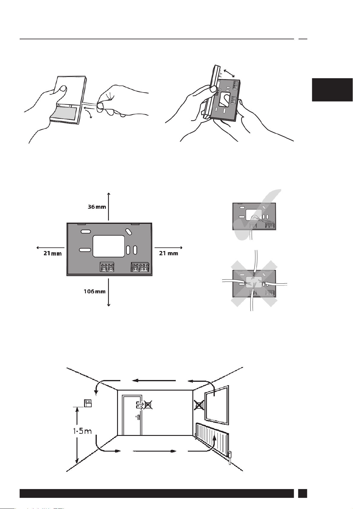
3.0 Installation
3.1 First remove the wallplate from the back of the unit.
3.2 From the top left hand corner of the wallplate, there must be
clearances of at least 21mm to the right, 21mm to the left, 36mm
above and 106mm below in order to mount the plug-in module.
GB
GB
3.3 Fix the TP70001/TP7001M and its optional remote room sensor
at a height of approximately 1.5m from the oor, away from
draughts or heat sources such as radiators, open res or direct
sunlight.
Danfoss Heating
5
Page 6
GBGB
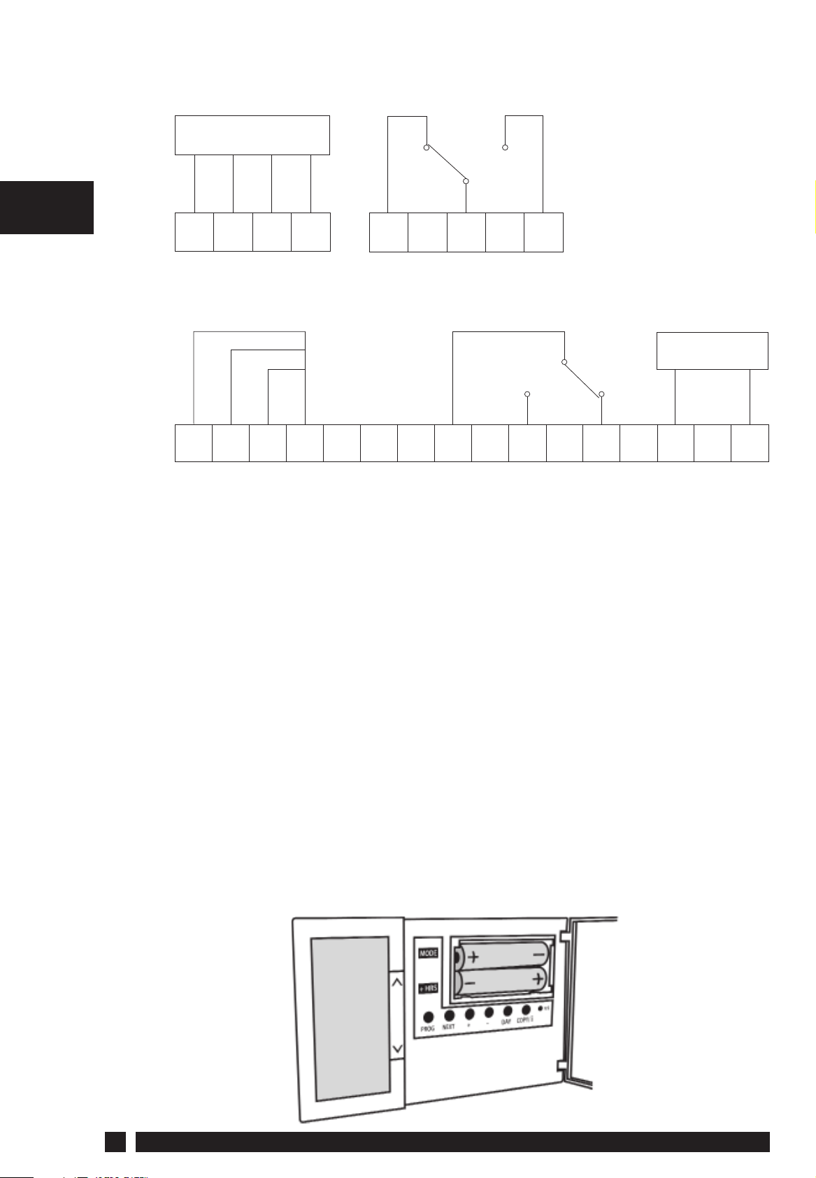
3.4 For wiring connections please refer to the diagrams below:
Battery Version
Room/outdoor/limit
sensor or contact
1
3
2
4
5
6
7
b
d
C
S COM
HTG
OFF
HTG
COM
HTG
ON
Mains Powered Version
Z
Y
X
1
b
X, Y and Z can be connected to
Room/Outdoor/Limit Sensor or contact
3
2
C
4
d
S COM
5
67
HTG
COM
HTG
ON
89
HTG
OFF
Power Supply
10
LN
The TP7001 and TP7001M can incorporate three inputs/sensor
types by using input b, C and d.
The sensor types are as follows:
1) Remote room temperature sensor (sold as an accessory).
2) Limit sensor, for example, oor temperature sensor (sold as an
accessory). Note: F10 in display - The under oor temperature has
exceeded the threshold temperature.
3) Outdoor sensor (sold as an accessory).
4) Window contacts, card reader contacts or teleswitch contacts.
Note: See Installer Advanced Programming Options for set-up
instructions.
3.5 For the TP7001 battery version, insert the batteries – making sure
that they are correctly oriented.
6
TP7001
Page 7

3.6 The unit can be made tamperproof if required by setting the
DIL switches which will disable the keyboard, and/or the reset
functions. The DIL switches are located on the back of the unit.
SW. No
SW.1
SW.2
OFF
Keyboard Disabled
Reset Disabled
ON
Keyboard Enabled
Reset Enabled
3.7 Mount the unit on the wallplate
Note: Always switch
the mains o rst
and never t/remove
the thermostat to/
from a live wallplate.
3.8 With the unit powered up, it is recommended to press and release
GBGB
the RESET button to start up the TP7001 unit.
4.0 Installer Advanced Programming Options
The TP7001 incorporates a number of advanced features which
can be set by the user. These are accessed via the User Advanced
Programming Mode, please refer to User Advanced Programming
in the User Instructions for details.
The TP7001 incorporates an additional number of advanced features
which can be set by the installer to improve the operating e ciency
of the system and where required, to change the user functionality
of the product. These are accessed via an Installer Advanced
Programming Mode. These settings are optional and need only be
accessed if there is a demand for the enhanced functions.
4.1 Service Interval Timer
Instructions on how to access this feature are available from our
customer support desk. Please note these are only issued to boni- de
heating installers.
Danfoss Heating
7
Page 8

4.2 Entering Installer Advanced Programming
To access the Installer Advanced Programming Mode
follow the steps below:
GB
a) Press and hold
User Advanced Programming, the display will
change to look like the image opposite.
b) Press and hold
Installer Advanced Programming, the display will
change to look like the image opposite.
c) Use the + and - keys to scroll backwards and forwards
between options then the
the option settings. The ashing digits in the centre
of the display indicate the number of the selected
option. The large characters in the top or bottom of
V and PROG for 3 seconds to enter
V, Λ and PROG for 5 seconds to enter
V and Λ keys to change
the display indicate the option value selected.
d) To return to RUN, press and hold PROG until the display returns
to previous RUN mode.
Option 30 - Set Temperature Upper Limit
This allows the upper limit of the thermostat setting
range to be limited. Press + until Option 30 is
displayed, use V or Λ to select required setting.
Can be set to any value between 40.0°C and 5°C in
0.5°C steps
Factory setting = 30°C
8
TP7001
Page 9

Option 31 - Set Temperature Lower Limit
This allows the lower limit of the thermostat setting
range to be limited. Press + until Option 31 is
displayed, use V or Λ to select required setting.
Can be set to any value between 5.0ºC and 40.0ºC in
0.5ºC steps
Factory setting = 5ºC
Option 32 - Enable O at Lower Limit
This enables an OFF function to be selected if a set
point below the lower limit is selected. Press + until
Option 32 is displayed, use V or Λ to select required
setting.
0 = Disabled
1 = Enabled (Factory setting)
Option 33 - Enable On at Upper Limit
This enables an ON function to be selected if a set
point above the upper limit is selected. Press + until
GB
Option 33 is displayed, use V or Λ to select required
setting.
0 = Disabled (Factory setting)
1 = Enabled
Option 34 - Select On/O or Chrono-Proportional
This allows the thermostat to be set to run in On/O
mode or for a chrono-proportional cycle rate to be
selected. Press + until Option 34 is displayed, use V or
Λ to select required setting.
0 = On/O
3 = 3 cycles/hour
6 = 6 cycles/hour (Factory setting)
9 = 9 cycles/hour
12 = 12 cycles/hour
Danfoss Heating
9
Page 10

Option 35 - Set Integration Time
(Option 34 set to 3, 6, 9 or 12)
This adjusts the integration time of the PI algorithm to
increase control accuracy. It is only active if Option 34
has been set to Chrono 3, 6, 9 or 12. It should only be
GB
adjusted after seeking advice from the manufacturer.
Press + until Option 35 is displayed, use V or Λ to
select required setting.
(NB Seek advice prior to adjusting)
2.5 = Integration time set to 2.5% (Factory Setting)
5 = Integration time set to 5%
10 = Integration time set to 10%
Option 36 - Set Temperature Override Rule
This establishes the degree of temperature override
available to the user. Press + until Option 36 is
displayed, use V or Λ to select required setting. This
option is not possible if the thermostat is set to STAT
in Option 40.
0 = No limit (Factory Setting)
1 = Limited to ±2ºC (±3ºF)
2 = No override allowed
Option 37 - Set Time Duration of Override Rule
This establishes the duration of a temperature
override available to the user. Press + until Option 37
is displayed, use V or Λ to select required setting. This
option is not possible if the thermostat is set to STAT
in Option 40 or Override Limit is disabled.
0 = Next Event (Factory Setting)
1 = 1 Hour
2 = 2 Hours
3 = 3 Hours
4 = 4 Hours
10
TP7001
Page 11

Option 38 - Relay State on Low Battery Detect
(Battery powered versions only)
This establishes the position that the relay is driven to
when the unit shuts down due to low battery state.
Press + until Option 38 is displayed, use V or Λ to
select required setting. This option is only possible on
battery versions.
0 = Output OFF (Factory setting)
1 = Output ON
Option 40 - Number of Events per Day
This sets the thermostat to operate with either 2, 4 or 6
switching events per day or to run in stat mode. Press
+ until Option 40 is displayed, use V or Λ to select
required setting.
1 = Stat
(Manual operation - no programming function)
2 = 2 Events per day
4 = 4 Events per day
GB
6 = 6 Events per day (Factory setting)
Option 41 - Operating Mode
(7 Day, 5/2 Day or 24 Hour)
This sets the thermostat to operate using either 7 day,
5/2 day or 24 hour mode. Press + until Option 41 is
displayed, use V or Λ to select required setting. This
option is not possible if the thermostat is set to STAT
in option 40.
7 = 7 Day (Factory Setting)
5-2 = 5+2 Day (or A-B if A days is set in option 1)
24 = 24 Hour
Danfoss Heating
11
Page 12

Option 70 - Keyboard Disable Rules
This establishes the degree of functionality of the
keyboard available to the user. It is only active if DIL
switch 1 is set to ‘disabled’. Press + until Option 70 is
displayed, use V or Λ to select required setting.
GB
0 = Normal Lock - Programming Functions Locked
(Factory Setting)
1 = Full Lock - All keys are disabled
Option 71 - Random Start Rules
(24V/230V versions only)
This enables a random start on power-up following a
power cut to reduce load on the electrical network.
Random delay is in the range of 2-90 seconds. Press
+ until Option 71 is displayed, use V or Λ to select
required setting.
0 = Disabled (Factory setting)
1 = Enabled
Option 72 - Owner Site Reference Number
This enables multi-site owners to store a site reference
number in the thermostat. Press + until Option 72 is
displayed, use V or Λ to select required setting.
00 (Factory setting)
01 to 99, with scroll over
Option 73 - Owner Thermostat Reference Number
This enables site owners to store a thermostat
reference number in the thermostat. Press + until
Option 73 is displayed, use V or Λ to select required
setting.
000 (Factory setting)
001 to 999, with scroll over
12
TP7001
Page 13

Option 74 - Date Format for Calendar Clock
This allows date format to be chosen. Press + until
Option 74 is displayed, use V or Λ to select required
setting.
0 = European (dd/mm/yy) (Factory setting)
1 = American (mm/dd/yy)
Option 75 – LCD Switch O
This option allows the measured temperature part of
the display to be disabled or all of the display to be
switched o when not in use.
Press + until Option 75 is displayed, use V or Λ to
select required setting.
0 = Display o after 5 minutes
1 = Measured Temperature display disabled
2 = LCD always active (Factory setting)
Option 80 - Enable / Disable + Hours Function
Enables or disables the +Hours button. Press + until
GB
Option 80 is displayed, use V or Λ to select required
setting.
0 = Disabled
1 = Enabled (Factory setting)
Option 81 - Thermometer Calibration Bias
This allows the thermostat calibration to be biased by
up to ±1.5°C. Press + until Option 81 is displayed, use
V or Λ to select required setting.
Any value between -1.5ºC and 1.5ºC in 0.5ºC steps
Factory setting is 0.0ºC
Danfoss Heating
13
Page 14

Option 90 - De ne Remote Sensor Type
(Remote sensor 1 - Backplate connection b)
This allows type of remote sensor input type to be
de ned. Press + until Option 90 is displayed, use V or
Λ to select required setting.
GB
0 = No Sensor (Factory setting)
1 = Remote room or Duct sensor, internal sensor
disabled
2 = Remote limit ( oor) sensor, de ne setpoint in
option 93
3 = Digital input for window, card reader, or teleswitch,
de ne functionality in option 94
4 = Outdoor temperature sensor (information only -
no control via sensor reading)
Option 91 - De ne Remote Sensor Type
(Remote sensor 2 - Backplate connection C)
This allows type of remote sensor input type to be
de ned. Press + until Option 91 is displayed, use V or
Λ to select required setting.
0 = No Sensor (Factory setting)
1 = Remote room or Duct sensor, internal sensor
disabled
2 = Remote limit ( oor) sensor, de ne setpoint in
option 93
3 = Digital input for window, card reader, or teleswitch,
de ne functionality in option 94
4 = Outdoor temperature sensor (information only -
no control via sensor reading)
14
TP7001
Page 15

Option 92 - De ne Remote Sensor Type
(Remote sensor 3 - Backplate connection d)
This allows type of remote sensor input type to be
de ned. Press + until Option 92 is displayed, use V or
Λ to select required setting.
0 = No Sensor (Factory setting)
1 = Remote room or Duct sensor, internal sensor
disabled
2 = Remote limit ( oor) sensor, de ne setpoint in
option 93
3 = Digital input for window, card reader, or teleswitch,
de ne functionality in option 94
4 = Outdoor temperature sensor (information only -
no control via sensor reading)
Note: Only one of each type of sensor may be tted - the choices
within options 90-92 will automatically be limited once remote
sensor types are chosen.
Option 93 - Set Limit Sensor Set-Point
(One of options 90-92 set to 2)
GB
This allows the thermostat limit sensor to be set,
typical application is oor heating. Press + until Option
93 is displayed, use V or Λ to select required setting. If
the temperature sensed by the limit sensor exceeds
the limit setting the output will be turned o until the
temperature has dropped by 2°C. “F10” will ash in the
display while the output is disabled.
This option is only possible if one remote sensor
option is set to Remote Limit (Floor) Sensor (Setting
2)
Any value between 20.0ºC and 50.0ºC in 0.5.0ºC steps
Factory setting is 27ºC
The temperature set for the limit point sensor will be determined by
the type of oor. The recommended limits are:
Tiles on chipboard and wooden oors 27°C
Carpet or vinyl on chipboard 35°C
Tiles on concrete oor 40°C
Concrete, screed, etc 45°C
Danfoss Heating
15
Page 16

Option 94 - Con gure Digital Input Switch Type
(One of options 90-92 set to 3)
This allows the switch type of the digital input to be
con gured. Press + until Option 94 is displayed, use V
or Λ to select required setting.
GB
This option is only possible if one remote sensor
option is set to Digital Input (Setting 3)
0 = Contacts Normally Closed, open circuit contact
to force unit into thermostat mode, short circuit
contacts to return to normal operation.
1 = Contacts Normally Open, short circuit contacts to
force unit into thermostat mode, open circuit contacts
to return to normal operation (Factory setting)
16
TP7001
Page 17

5.0 How to Reset the Unit
5.1 Partial reset
Partial reset is used if the display freezes for any reason.
1. Press and release the RESET button.
This does not reset any programmes or the time or date. It will
GB
simply restore operation in the unlikely event the unit has become
unresponsive.
5.2 User full reset
1. Hold down the PROG button
2. Press and release the RESET button
This resets event times and any User Advanced Programme settings,
but does not reset time or date.
5.3 Installer full reset
1. Press and hold V and PROG for approx. 3 seconds to enter User
Advanced Programming
2. Press and hold V, Λ and PROG for approx. 5 seconds to enter
Installer Advanced Programming
3. Hold down the PROG button
4. Press and release the RESET button
This resets event times and all User and Installer Advanced
Programming settings and returns them to factory settings, however,
time, date and service due date are not reset.
Danfoss Heating
17
Page 18

18
TP7001
Page 19

Danfoss Heating
19
Page 20

Danfoss Ltd.
Ampthill Road
Bedford MK42 9ER
Tel: 01234 364621
Fax: 01234 219705
Email: ukheating@danfoss.com
Website: www.heating.danfoss.co.uk
Part No. 37034v02 11/12
 Loading...