

Page 1
TP5001 Range
Electronic Programmable Room Thermostat
Danfoss Heating
MAKING MODERN LIVING POSSIBLE
Installation Guide
Page 2
2
Installation Instructions
Important note RF products: Ensure that there are no large metal objects, such as boiler cases
or other large appliances, in line of sight between the transmitter and receiver as these will
prevent communication between thermostat and receiver.
Product Specifi cation
Please Note:
This product should only be installed by a qualifi ed electrician
or competent heating installer and should be in accordance
with the current edition of the IEEE wiring regulations.
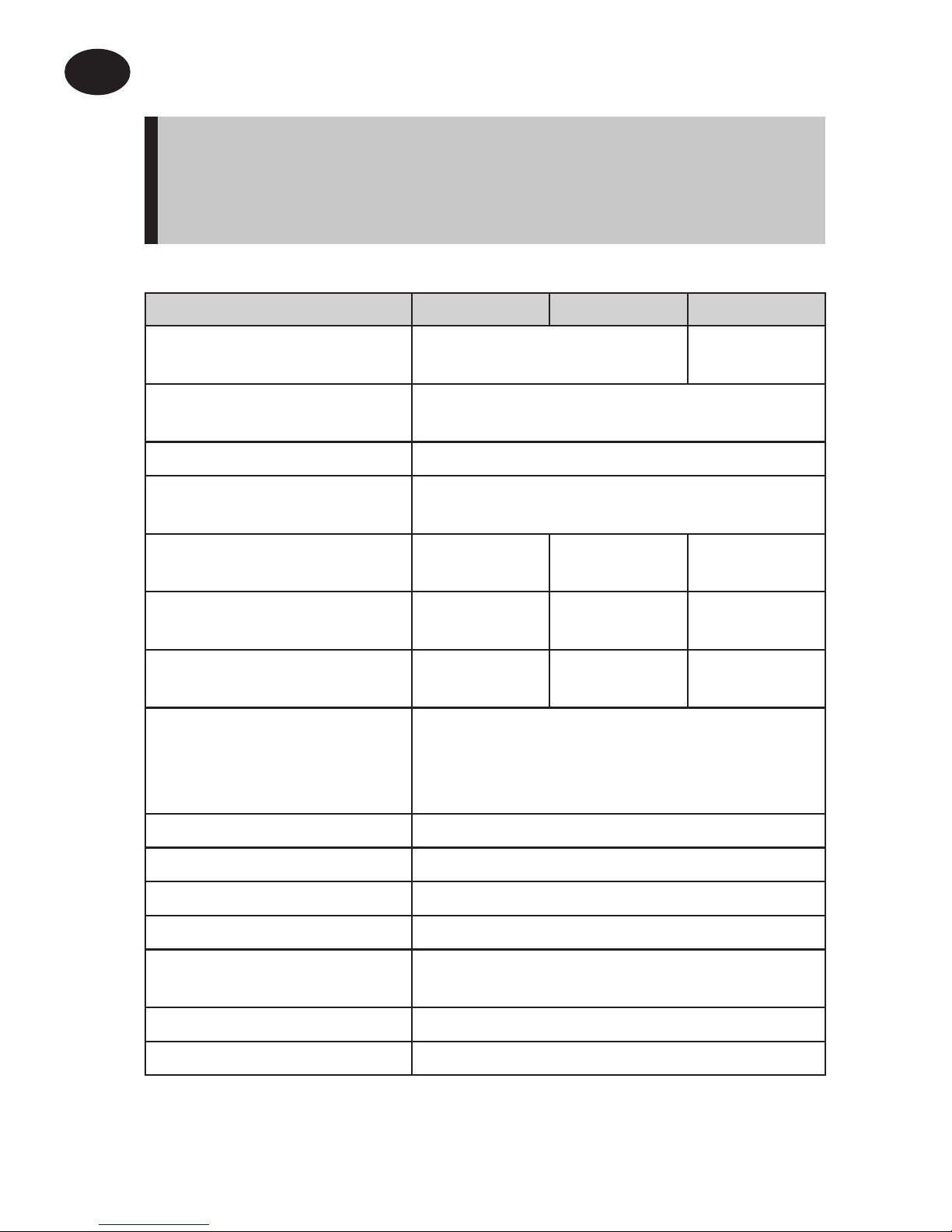
Thermostat features TP5001 (A) TP5001-RF TP5001M (A)
Power supply 2 x AA/MN1500/LR
alkaline cells
230V, ±15%,
50Hz
Memory back-up Retained for life of product
Temperature Range
Sensing
5-30°C
Factory set calendar clock Automatic summer/winter time change
Switching action of
output relay
3(1)A,
10-230V
N/A 3(1)A, 10-230V,
Type 1B
Transmission frequency
(RF models)
N/A 433.92MHz N/A
Transmission range
(RF models)
N/A 30m max. N/A
Remote sensor inputs
(A models only)
Can be set by installer for remote temperature sensor,
limit sensor, window contact or telephone activated
switch contacts
Dimensions (mm) 110 wide, 88 high, 28 deep
Design standard EN60730-2-9 (EN300220 for RF)
Rated impulse voltage 2.5kV
Ball hardness test 75°C
Control pollution
situation
Degree 2
Temperature accuracy ±1°C
Time accuracy ±1 min. per month
Installation Instructions
GB
Page 3
3
Installation Instructions
GB
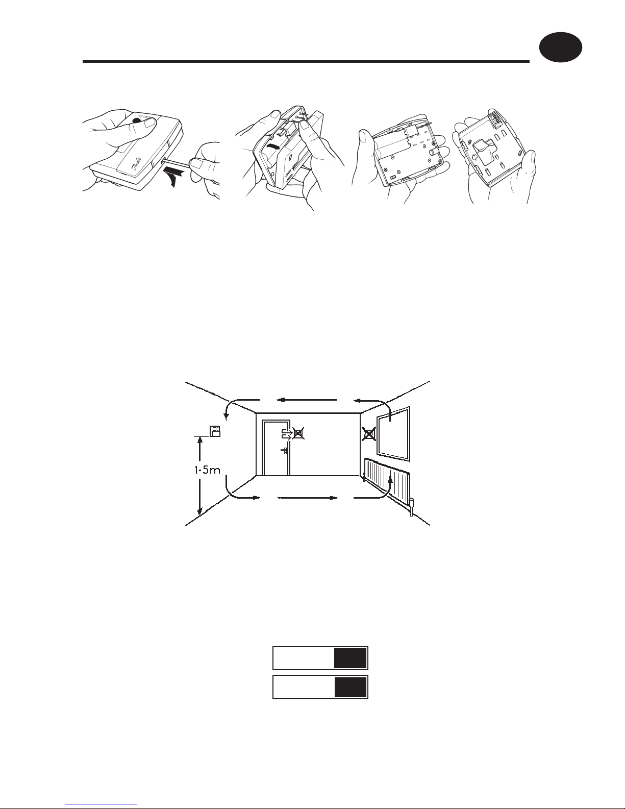
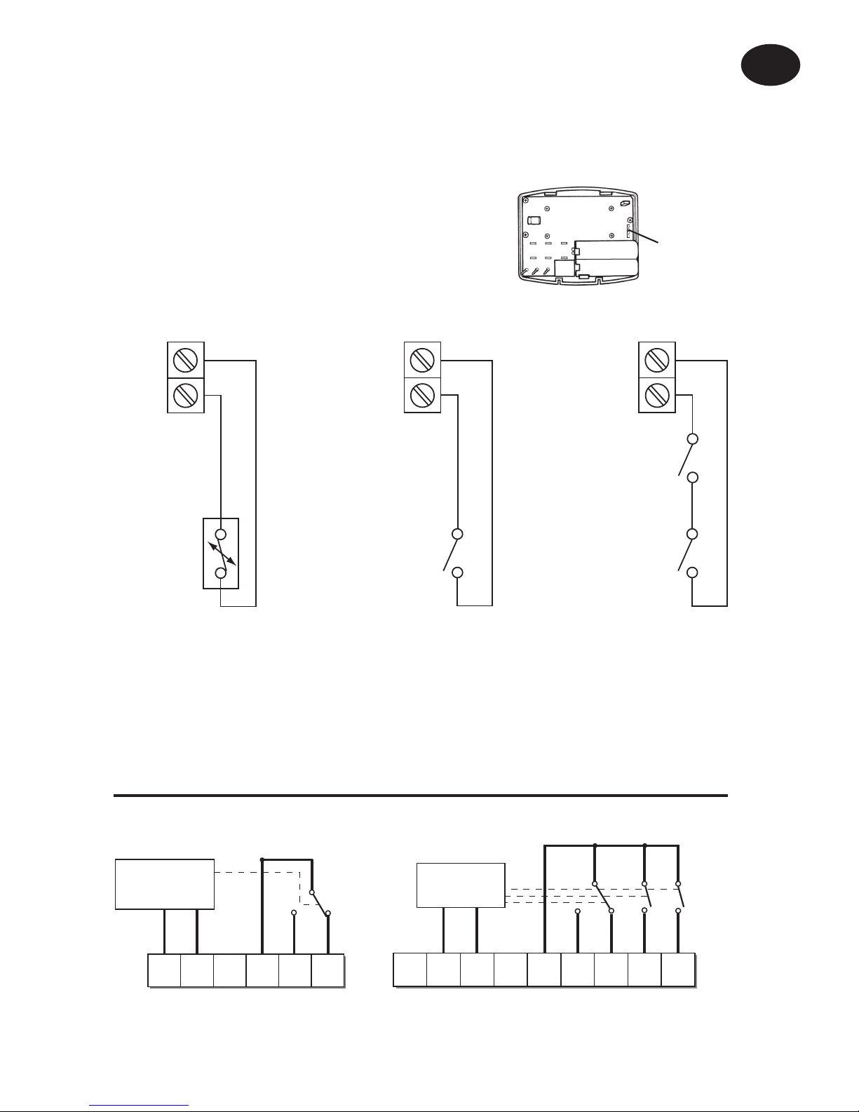
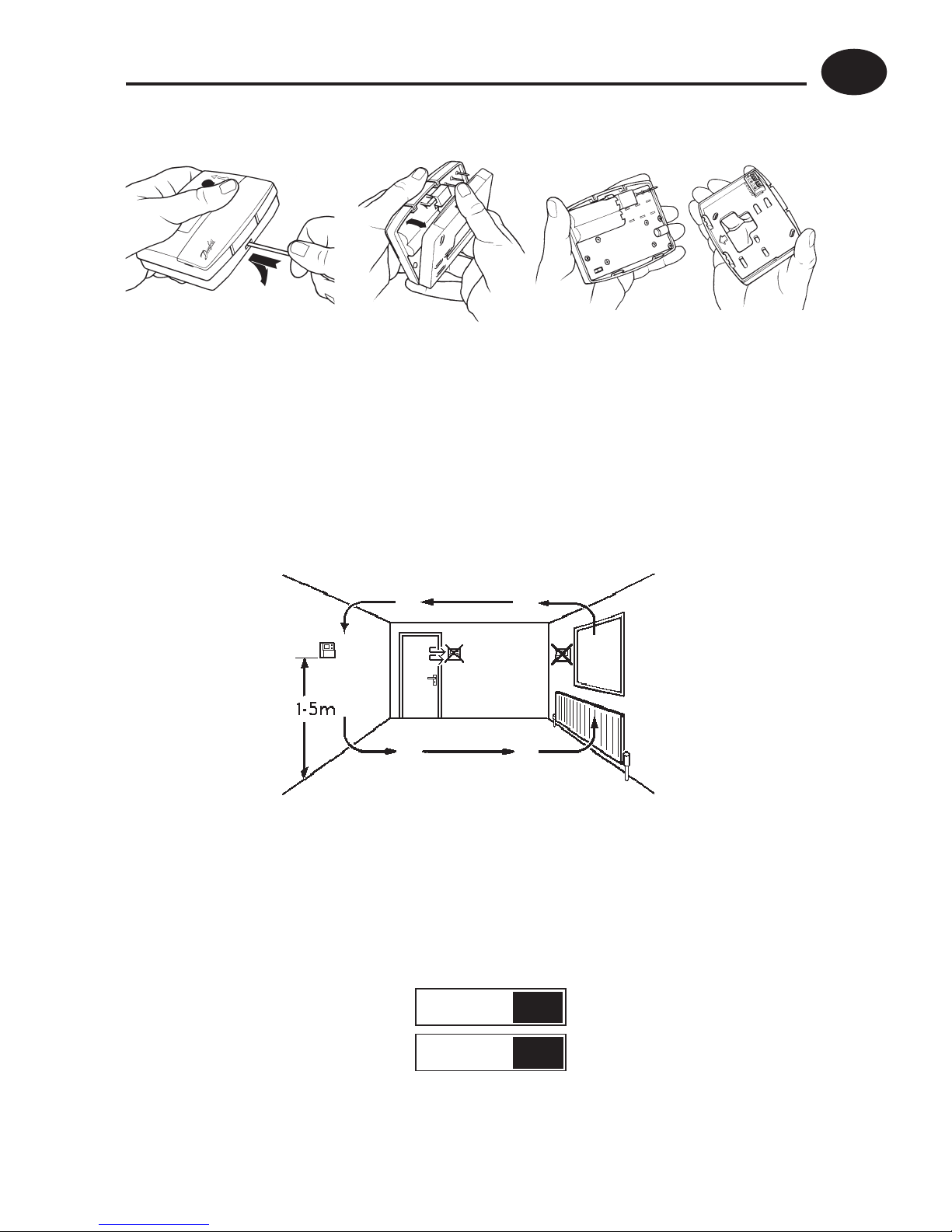
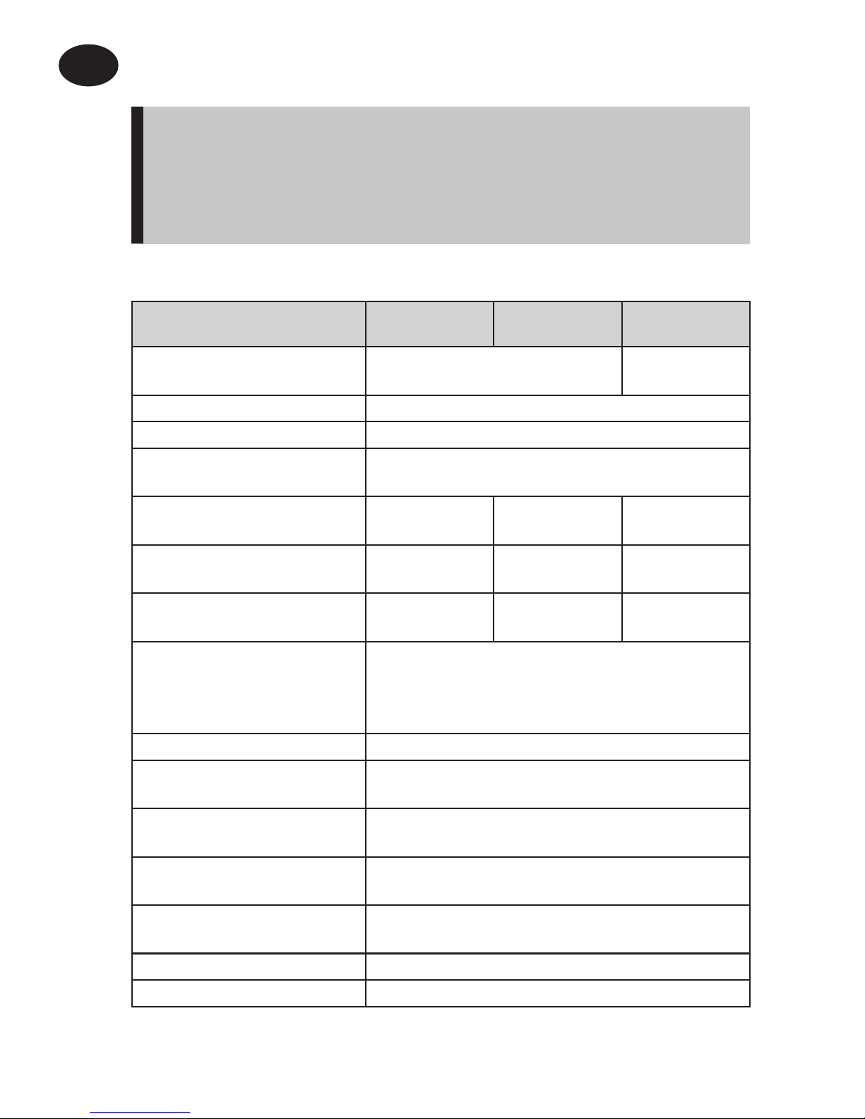
Installation
• First, remove the wallplate from the back of the unit.
• From the top left hand corner of the wallplate, there must be
clearances of at least 15mm to the right, 15mm to the left, 30mm
above and 100mm below in order to mount the plug-in module.
• Thermostat and Remote Room Sensor:
Fix at a height of approximately 1.5m from the fl oor, away from
draughts or heat sources such as radiators, open fi res or direct
sunlight.
• Prior to mounting the unit the 2 DIL switches on the rear of the
unit have to be moved to the required position. The factory
presets are shown below.
1
2
Keyboard disabled
Reset disabled Reset enabled
Keyboard enabled
OFF
ON
Sw. No.
Page 4
4
Installation Instructions
GB
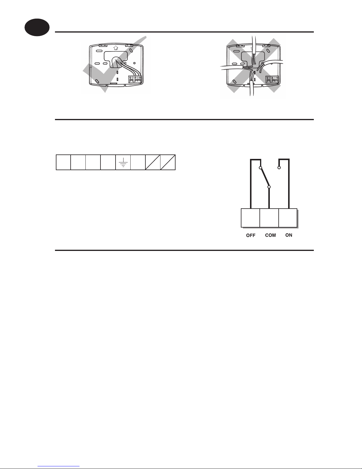
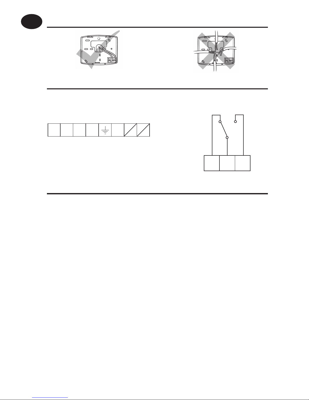
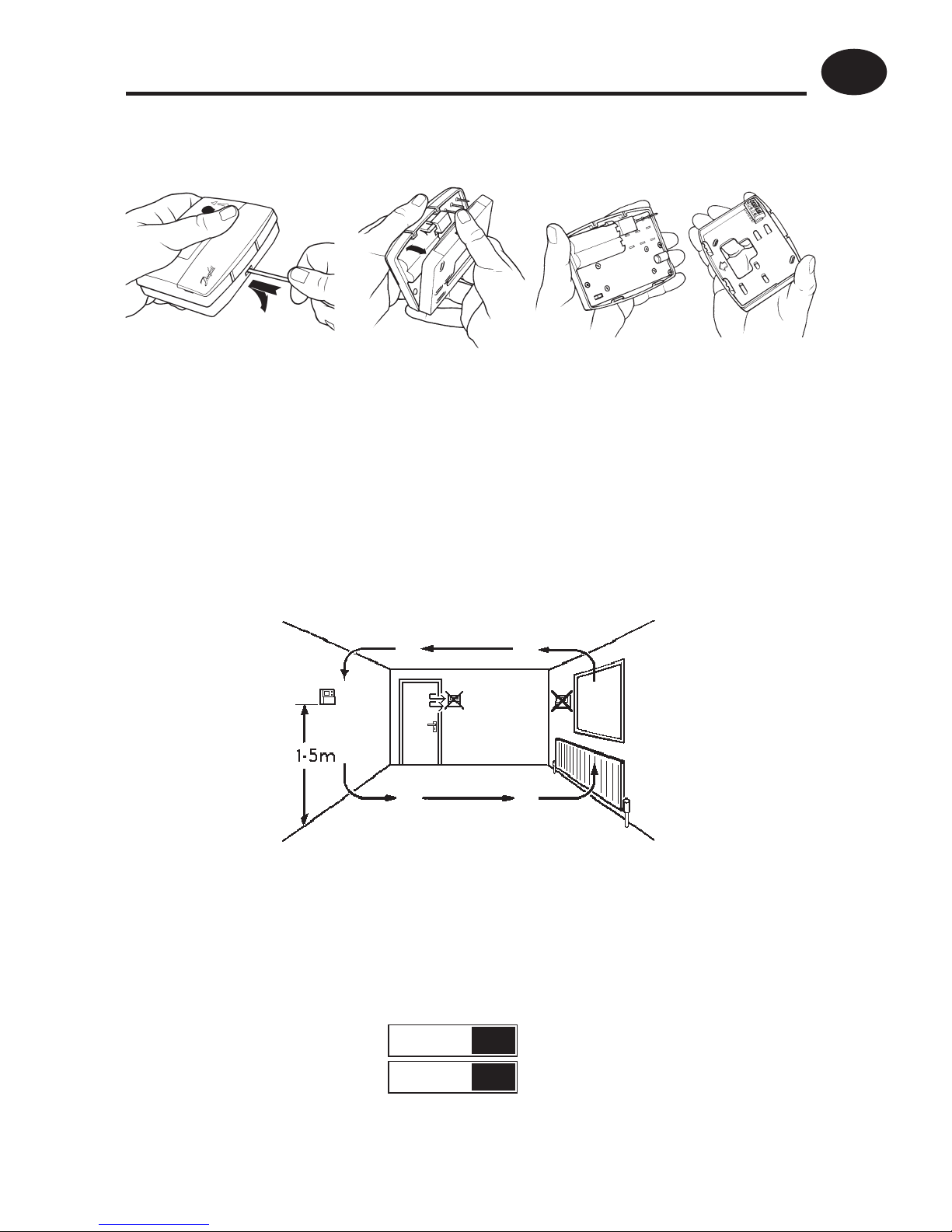
!
Some existing thermostats will have a Neutral and/or Earth wire connected. These
are not required by the TP5001 (battery models) and must NOT be connected to any
TP5001 terminals. Instead they should be made electrically safe and coiled in the
recess at the back of the TP5001.
Cable Access
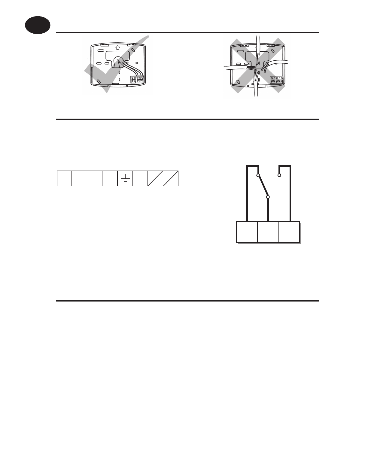
Wiring - TP5001
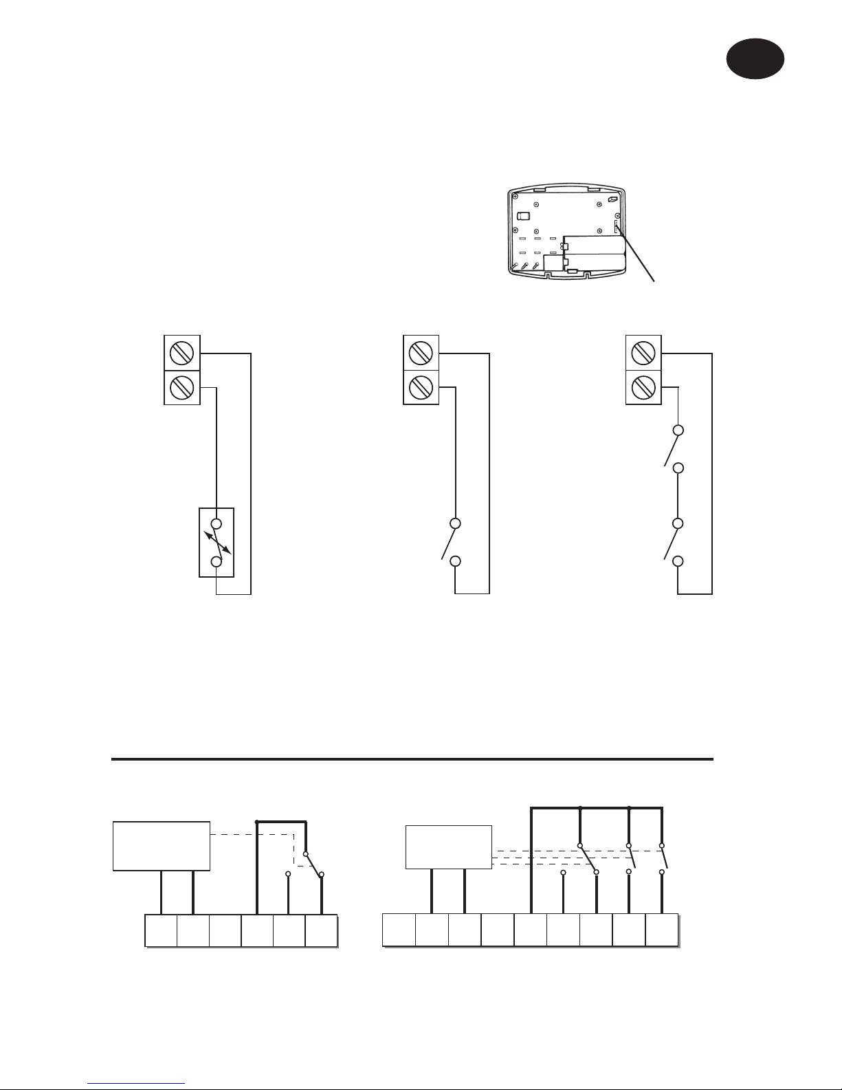
Models with remote sensor inputs
TP5001A and TP5001MA incorporate an input which can be used to
connect one of the following:
1) remote room temperature sensor (sold as accessory).
Battery Installation
When installing the batteries in the TP5001 and TP5001 RF please
ensure that the correct polarity is observed as per the markings on the
inside of the battery compartment.
Important: After installing the batteries press and release the RESET
button to start the unit. The display may appear blank until this is
done. Once the button is released the display will appear. All date, time,
programming and override settings are maintained for the life of the
product.
1
2
3
Output Connections,
all hard wired models
L
N
DE
S1 S2
Remote Sensor
(A version only)
M 230V Models
Page 5
5
Models with remote sensor inputs
Terminal block for remote control/sensing
is located on the circuit board above the
battery compartment.
RX1
RX2 & RX3
12
3
4
ELECTRONICS
N
L
COM
ZONE
1 ON
ZONE
1 OFF
A
ELECTRONICS
B
C1
2
345
6
N
L
ZONE
1 ON
ZONE
1 OFF
ZONE
2 ON
ZONE
3 ON
COM
TERMINAL 6
RX3 ONLY
RX Receiver Wiring (RF models only)
1) For mains voltage operated systems link terminal 2 to mains live supply.
2) Power supply to unit must not be switched by timeswitch.
Installation Instructions
GB
S1/D
S2/E
S1/D
S2/E
Window or
teleswitch
contact
(NO or NC)
Teleswitch
contact (NC)
Window
contact (NC)
S1/D
S2/E
Confi gured for
remote room
sensor or limit
sensor
Confi gured for
window contact or
other contact such
as teleswitch
Confi gured for
window contact
and other contact
such as teleswitch
/
D
/
E
Remote
control
connections
2) limit sensor, for example, fl oor temperature sensor (sold as
accessory).
3) window contacts, card reader contacts or teleswitch contacts.
See Installer Advanced Programming Options for set-up instructions.
Page 6

6
Commissioning (RF models only)
If the thermostat and the receiver have been supplied together in
a combined pack, the units have been paired in the factory and no
commissioning is required (RX1 only).
To tune the RX receiver to the frequency of the thermostat signal, follow
steps 1-5 below.
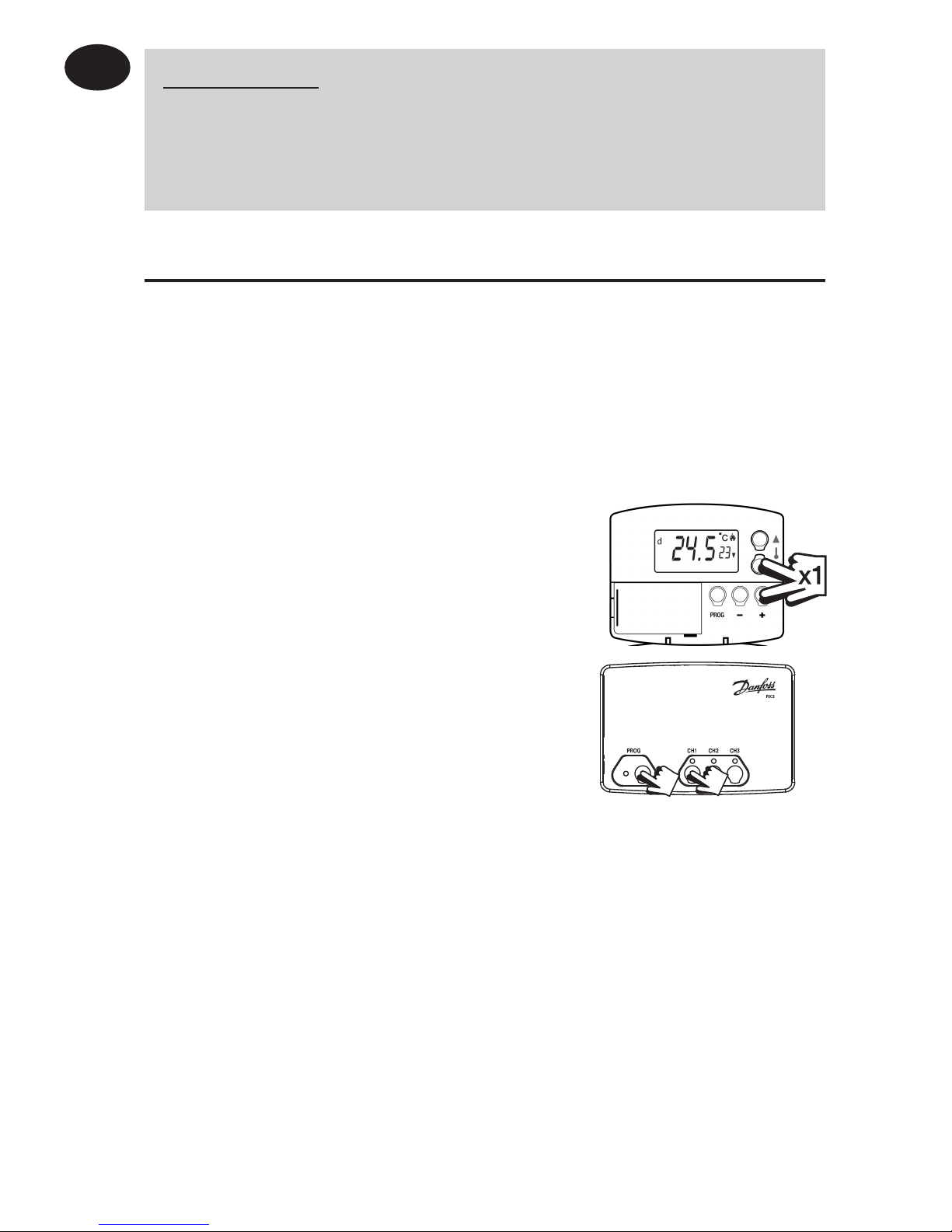
Step 1 TP5001-RF
Reset the unit by pressing the recessed
reset button.
Step 2 Press and hold V and + buttons for 3
seconds (TP5001-RF now transmits unique
signal continuously for 3 minutes).
Step 3 RX1
Press and hold buttons PROG and CH1 for
3 seconds until green light fl ashes once.
Step 4 RX2 (if applicable)
Stat 1 - perform steps 1-3 and 5.
Stat 2 - perform steps 1-2 and then press PROG and CH2 on RX2.
RX3 (if applicable)
Stat 1 - perform steps 1-3 and 5.
Stat 2 - perform steps 1-2 and then press PROG and CH2 on RX3 then
step 5.
Stat 3 - perform steps 1-2 and then press PROG and CH3 on RX3.
Step 5 TP5001-RF
Press V or Λ to select temperature - the unit will revert back to operating
mode.
Installation Instructions
GB
IMPORTANT
To ensure that the factory programmes are set and the microcomputer is operating correctly it is essential that you press and
hold the RESET button before you begin any commissioning or
programming.
Page 7
7
Installation Instructions
GB
Installer advanced
programming options
TP5001 incorporates a number of advanced features which can be
set by the user. These are accessed via a User Advanced Programming
Mode, please refer to User Advanced Programming in the user
instructions for details.
Installer advanced programming options
TP5001 incorporates an additional number of advanced features which
can be set by the installer to improve the operating effi ciency of the
system and where required, to change the user functionality of the
product. These are accessed via an Installer Advanced Programming
Mode. These settings are optional and need only be made if there is a
demand for the enhanced functions.
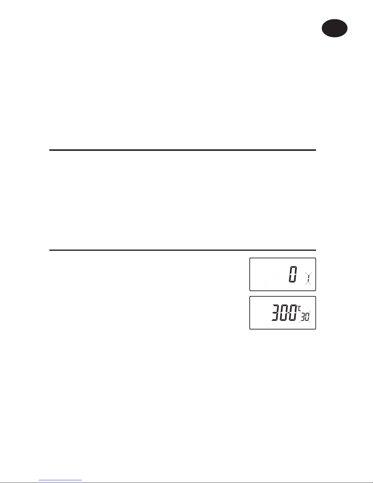
Entering Installer Advanced Programming mode
To access the Installer Advanced Programming
Mode follow the steps below:
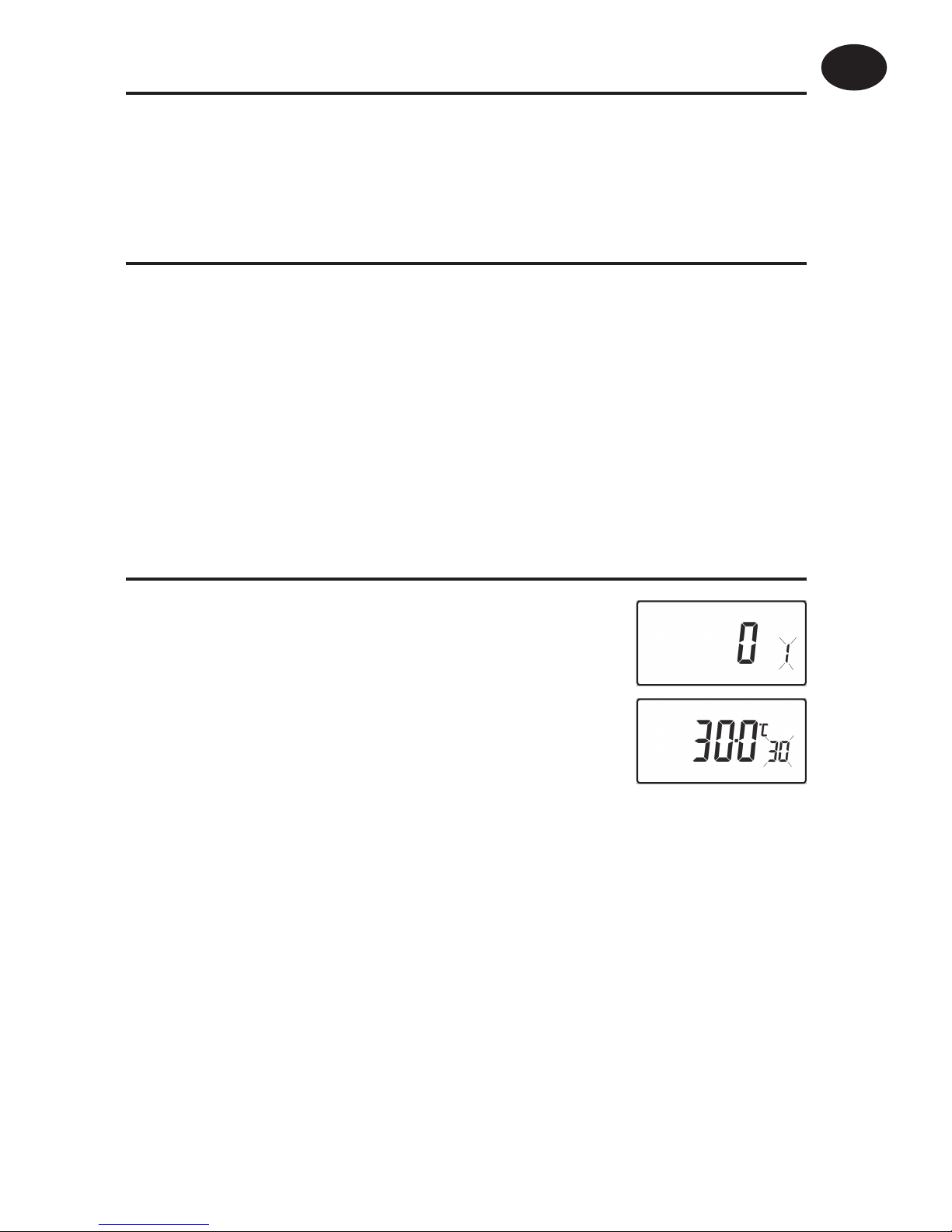
a) Press and hold
V and PROG for 3 seconds to
enter User Advanced Programming, the display
will change to fi gure opposite.
b) Press and hold
V, Λ and PROG for 5 seconds
to enter Installer Advanced Programming, the
display will change to fi gure opposite.
c) Use + and - keys to scroll backwards and forwards between options
then
V and Λ keys to change the option settings. The fl ashing digit
on the right hand of the display indicates the number of the selected
option. The large characters display the option value selected.
d) To return to RUN, press and hold PROG until colon in the display
blinks.
Page 8
8
Installation Instructions
GB
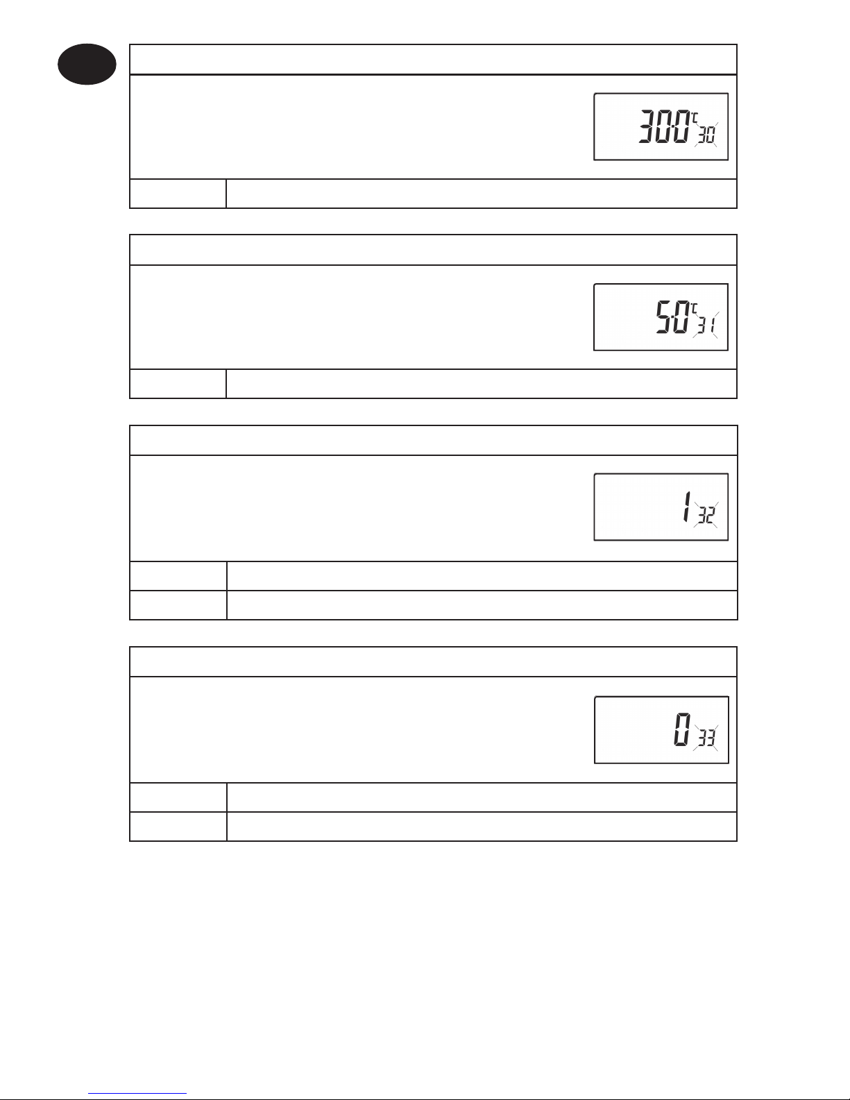
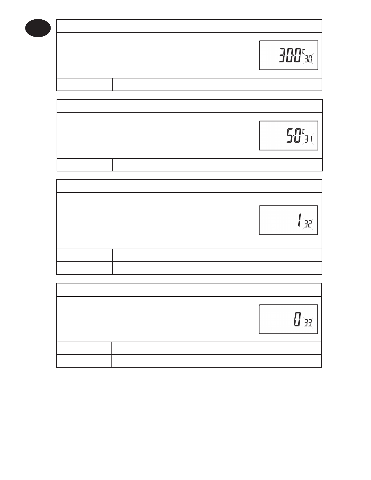
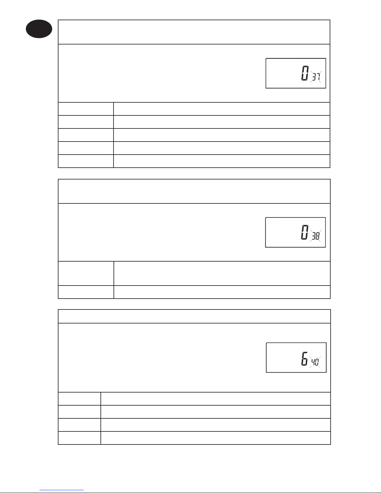
Option 30 - Set upper limit of temperature range
This allows the upper limit of the thermostat
setting range to be electronically limited. Press +
until Option 30 is displayed, use V and Λ to select
required setting.
Setting 40 - 5°C (Factory setting is 30°C)
Option 31 - Set lower limit of temperature range
This allows the lower limit of the thermostat
setting range to be electronically limited. Press +
until Option 31 is displayed, use V and Λ to select
required setting.
Setting 5 - 40°C (Factory setting is 5°C)
Option 32 - Enable Off at lower limit
This enables an OFF function to be selected if a set
point below the lower limit is selected. Press + until
Option 32 is displayed, use
V and Λ to select required
setting.
Setting 0 Disabled
Setting 1 Enabled (factory setting)
Option 33 - Enable On at upper limit
This enables an ON function to be selected if a set
point above the upper limit is selected. Press + until
Option 33 is displayed, use
V and Λ to select required
setting.
Setting 0 Disabled (factory setting)
Setting 1 Enabled
Page 9
9
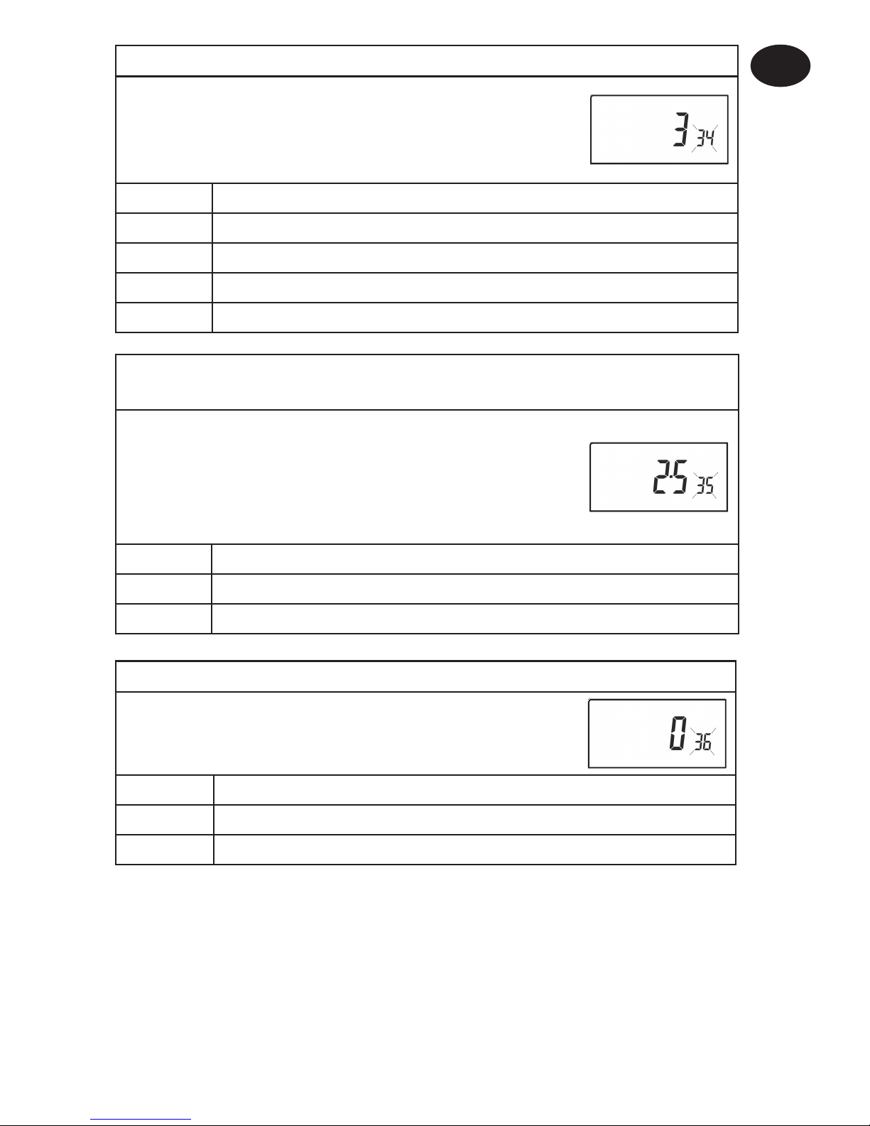
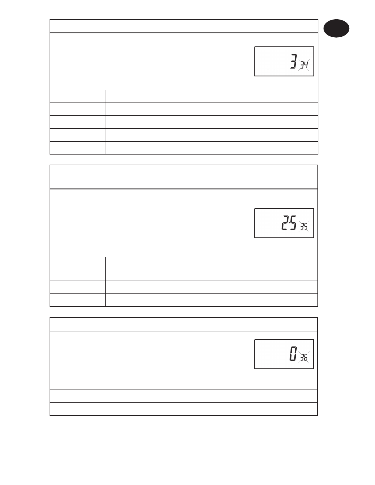
Option 34 - Select on/off or chrono-proportional
This allows the thermostat to be set to run in On/Off
mode or for a chrono-proportional cycle rate to be
selected. Press + until Option 34 is displayed, use V
and Λ to select required setting.
0 On/Off
3 3 cycles per hour
6 6 cycles per hour (factory setting)
9 9 cycles per hour
12 12 cycles per hour
Installation Instructions
GB
Option 35 - Set integration time (Option 34 set to 3, 6, 9 or 12)
(seek advice prior to adjusting)
This adjusts the integration time of the PI
algorithm to increase control accuracy. It should
only be adjusted after seeking advice from the
manufacturer. Press + until Option 35 is displayed,
use
V and Λ to select required setting.
2.5 Integration time set to 2.5% (factory setting)
5 Integration time set to 5%
10 Integration time set to 10%
Option 36 - Set temperature override rule
This establishes the degree of temperature override
available to the user. Press + until Option 36 is
displayed, use
V and Λ to select required setting.
Setting 0 No limit (factory setting)
Setting 1 Limited to ±2°C
Setting 2 No override allowed
Page 10
10
Installation Instructions
GB
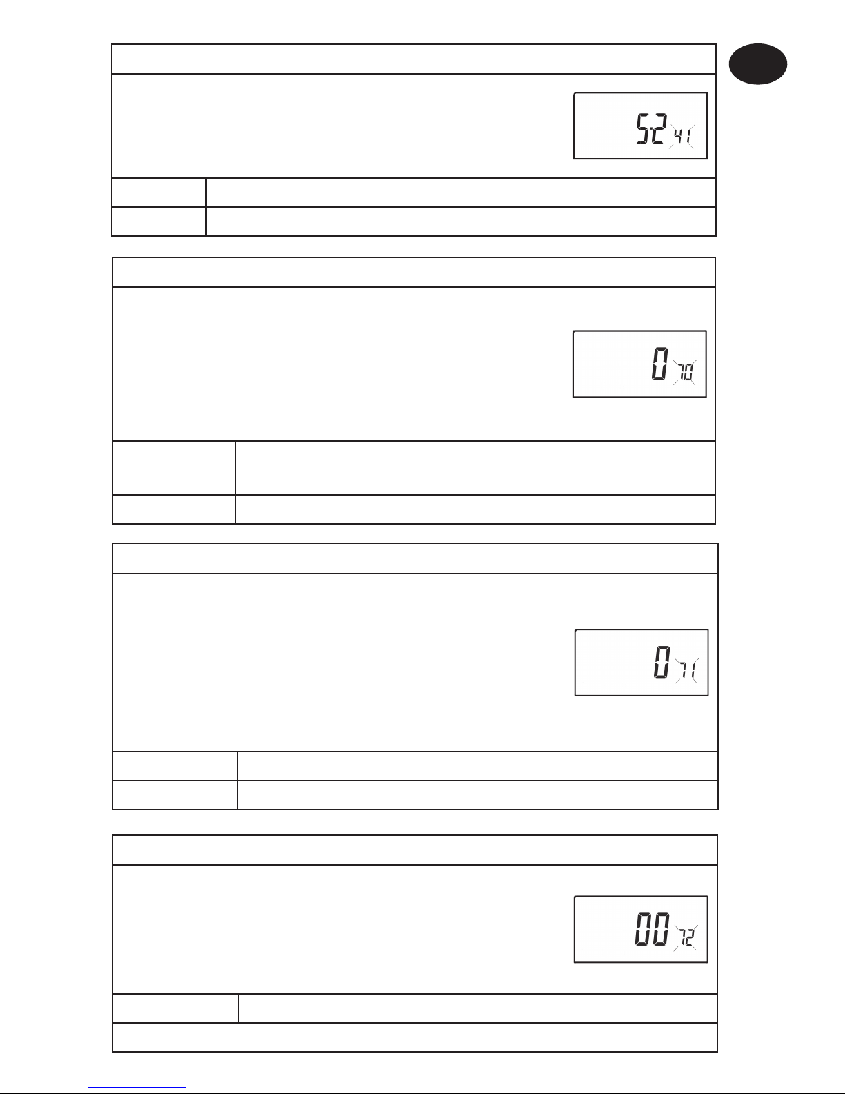
Option 38 - Relay state on low battery detect
(battery products only)
This establishes the position that the relay is driven
to when the unit shuts down due to low battery
state. Press + until Option 38 is displayed, use
V and
Λ to select required setting.
Setting 0 Relay parked with output OFF (factory setting)
Setting 1 Relay parked with output ON
Option 37 - Set time duration of override rule
(Option 36 set to 1 or 2)
This establishes the duration of a temperature
override available to the user. Press + until Option
37 is displayed, use V and Λ to select required
setting.
Setting 0 Next event (factory setting)
Setting 1 1 hour
Setting 2 2 hours
Setting 3 3 hours
Setting 4 4 hours
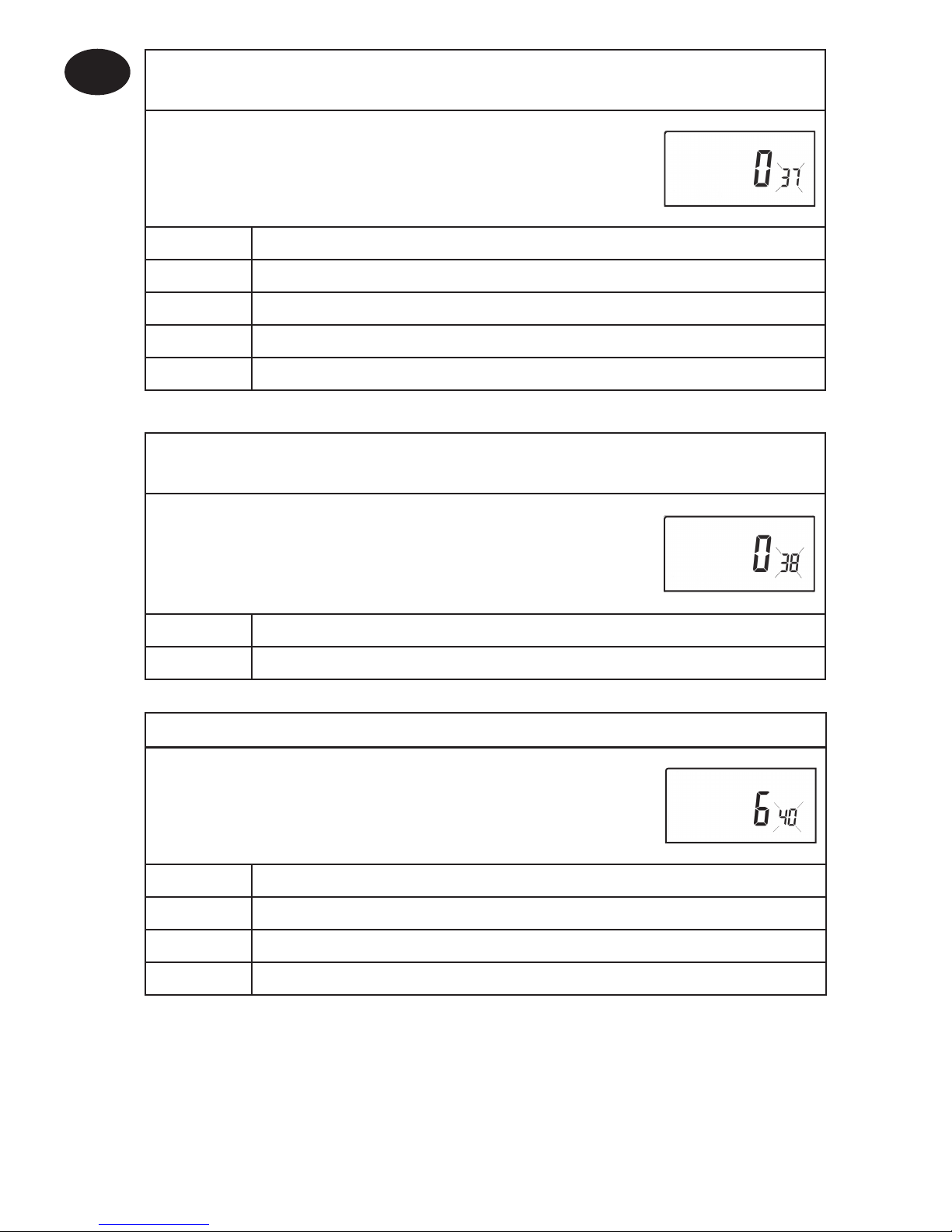
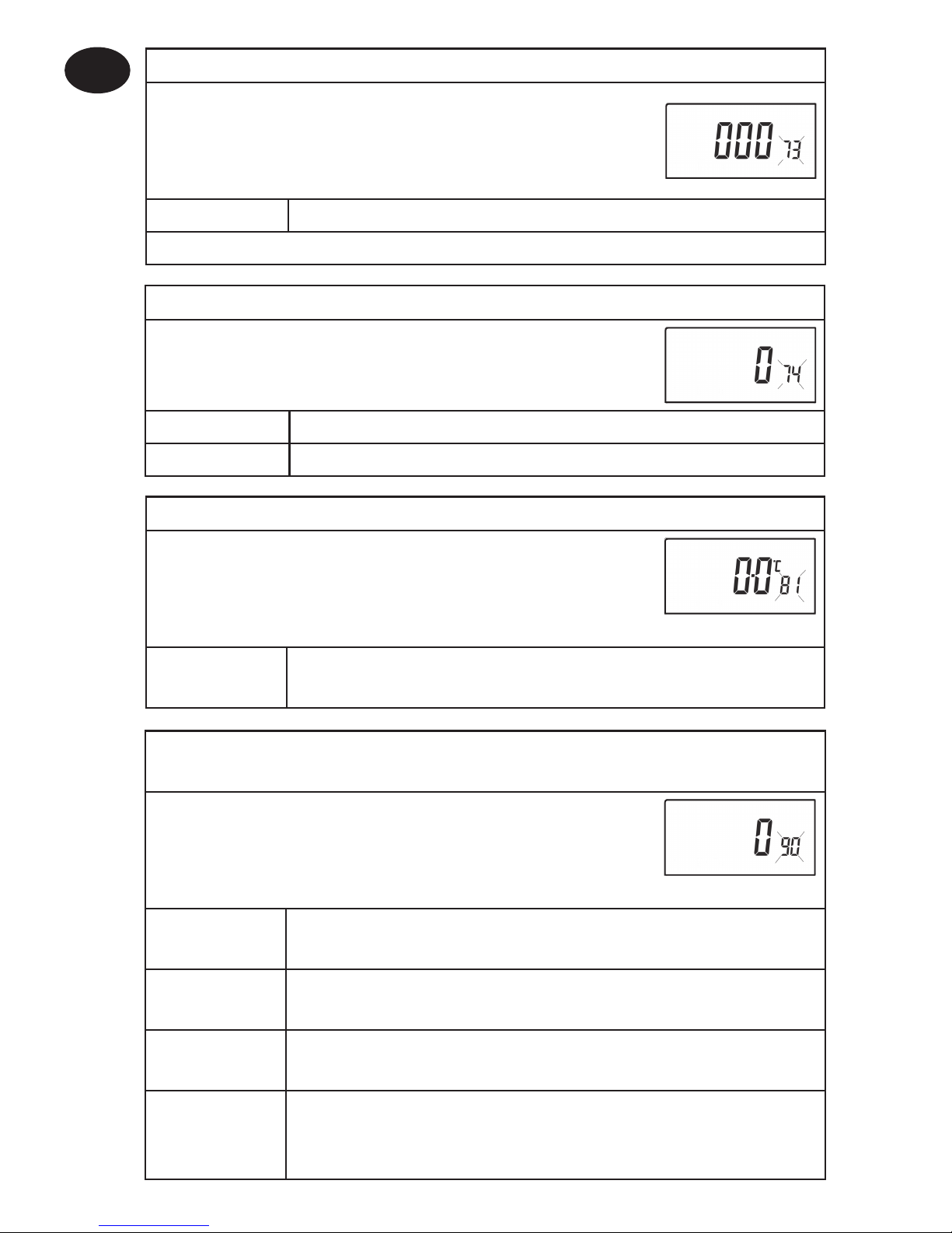
Option 40 - Number of Events per Day
This sets the thermostat to operate with either 2,
4 or 6 switching events per day or to run it in stat
mode. Press + until option 40 is displayed, use Λ or
V to select required setting.
1 Stat mode
2 Two switching events per day
4 Four switching events per day
6 Six switching events per day (Factory setting)
Page 11
11
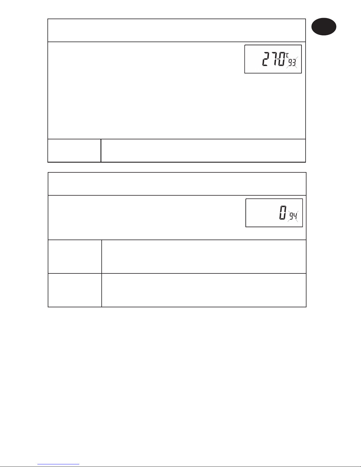
Option 70 - Keyboard disable rules
This establishes the degree of functionality of the
keyboard available to the user. It is only active if DIL
switch 1 is set to “Disabled”. Press + until Option 70 is
displayed, use V and Λ to select required setting.
Setting 0 Normal lock: Programming functions locked (factory setting)
Setting 1 Full lock: All keys are disabled
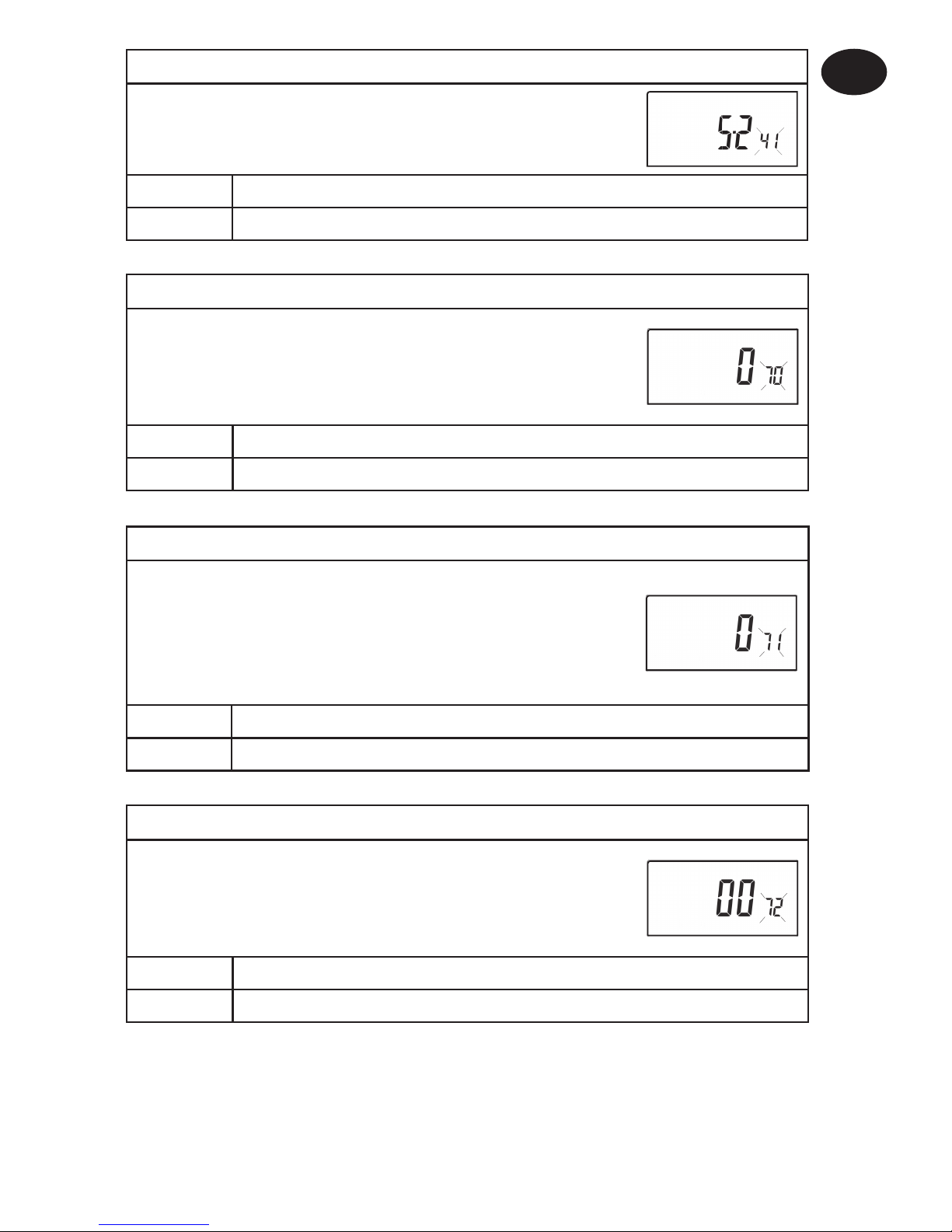
Option 71 - Random start rules (24V/230 Volt models only)
This enables a random start on power-up following a
power cut to reduce load on the electrical network.
Random delay is in the range of 2 - 90 seconds. Press
+ until Option 71 is displayed, use V and Λ to select
required setting.
Setting 0 Disabled (factory setting)
Setting 1 Enabled
Installation Instructions
GB
Option 41 - Operating Mode (5/2 day or 24 hour)
This sets the thermostat to operate using either
5/2 day or 24 hour mode. Press + until option 41 is
displayed, use Λ or V to select required setting.
5-2 5/2 day (Factory setting)
24 24 hour
Option 72 - Owner site reference number
This enables multi-site owners to store a site
reference number in the thermostat. Press +
until Option 72 is displayed, use V and Λ to select
required setting.
Setting Any value between 00 and 99 can be set
Factory setting is 00
Page 12
12
Option 90 - Defi ne remote sensor type, “A” models only
This allows type of remote sensor input type to be
defi ned. Press + until Option 90 is displayed, use V
and Λ to select required setting.
Setting 0 No remote sensor fi tted (Factory setting)
Setting 1 Remote room or duct sensor fi tted, internal sensor
disabled
Setting 2 Remote limit sensor fi tted, refer to option 93 to defi ne set-point
Setting 3 Confi gured as digital input for window, card reader or
teleswitch, refer to option 94 to defi ne o/c or s/c.
Option 81 - Thermstat calibration bias
This allows the thermostat calibration to be biased by
up to ±1.5°K. Press + until Option 81 is displayed, use
V and Λ to select required setting.
Setting Any value between ±1.5 (Factory setting is 0°C)
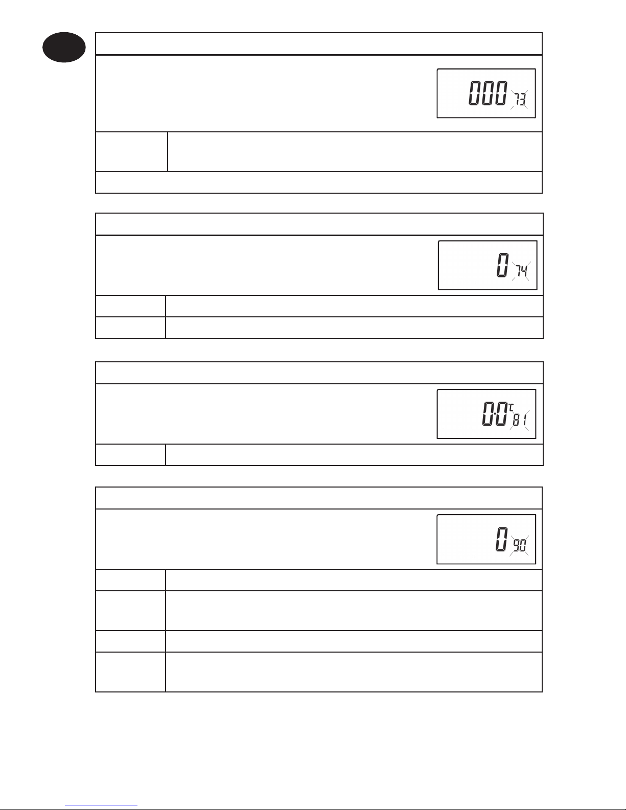
Option 74 - Date format for calendar clock
This allows date format to be chosen. Press +
until Option 74 is displayed, use V and Λ to select
required setting.
Setting 0 European rules (dd/mm/yy), (Factory setting)
Setting 1 North American rules (mm/dd/yy)
Option 73 - Owner thermostat reference number
This enables site owners to store a thermostat
reference number in the thermostat. Press + until
Option 73 is displayed, use V and Λ to select required
setting.
Setting Any value between 000 and 999 can be set
Factory setting is 000
Factory setting is 000
Installation Instructions
GB
Page 13
13
Option 93 - Set limit sensor set-point, “A” models only,
(option 90 set to 2)
This allows the thermostat limit sensor to be set,
typical application is fl oor htg. Press + until Option
93 is displayed, use V and Λ to select required
setting. If the temperature sensed by the limit
sensor exceeds the limit setting the output will be
turned off untill the temperature has dropped by
2°C “F10” will fl ash in the display.
Setting Any value between 20 - 50°C (Factory setting is 27°C)
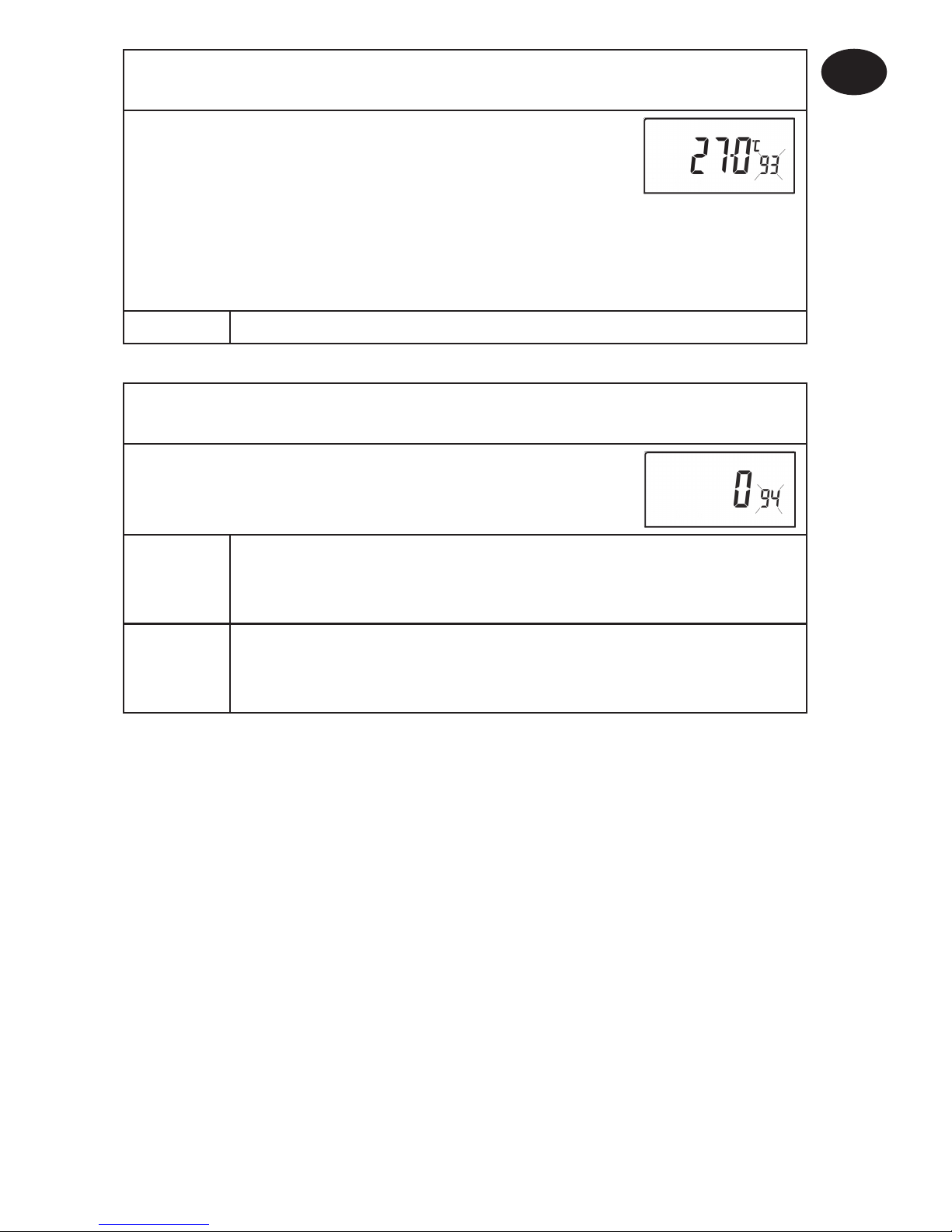
Option 94 - Confi gure digital input switch type, “A” models only,
(option 90 set to 3)
This allows switch type of digital input to be
confi gured. Press + until Option 94 is displayed, use
V and Λ to select required setting.
Setting 0 Contacts NC, open circuit contact to force unit into
thermostat mode, short circuit contacts to return to normal
operation
Setting 1 Contacts NO, short circuit contacts to force unit into
thermostat mode, open circuit contacts to return to normal
operation (Factory setting)
Installation Instructions
GB
Page 14
14
Installationsanleitung
Wichtiger Hinweis für RF-Produkte: Achten Sie darauf, dass sich keine großen metallischen
Objekte wie Heizkesselgehäuse oder andere große Geräte in direkter Linie zwischen Sender und
Empfänger befi nden. Die Kommunikation zwischen Thermostat und Empfänger wird dadurch
beeinträchtigt.
Produktspezifi kation
Bitte beachten Sie:
Dieses Produkt darf nur von einem qualifi zierten Elektriker oder
Heizungsinstallateur gemäß der aktuellen Version der IEEEVerkabelungsvorschriften installiert werden.
Merkmale des Thermostaten TP5001 (A) TP5001-RF TP5001M (A)
Spannungsversorgung 2 Alkalibatterien Typ AA /
MN1500 / LR
230V, ±15%,
50Hz
Datenerhalt der
gespeicherten Informationen
während der gesamten Produktlebensdauer
Temperaturbereich
5 bis 30°C
Werks-Voreinstellung von
Kalender und Uhrzeit
automatischer Wechsel zwischen
Sommer- und Winterzeit
Schaltleistung des
Ausgangsrelais
3(1) A, 10 bis
230 V
n.v. 3(1)A, 10-230V,
Type 1B
Sendefrequenz
(RF-Modelle)
n.v. 433,92 MHz n.v.
Sendereichweite
(RF-Modelle)
n.v. max. 30 m n.v.
Eingänge für entfernte
Sensoren (nur A-Modelle)
können vom Installateur für entfernten
Temperatursensor, Grenzwertsensor,
Fensterkontakt oder telefonaktivierte
Schaltkontakte eingestellt werden
Abmessungen (B x H x T) 110 x 88 x 28 mm
geltende Norm EN60730-2-9 (EN300220 für RF)
Nennstoßspannung 2,5 kV
Kugel-Härteprüfung 75°C
Verschmutzungssituation
Steuergerät
normal
Temperaturgenauigkeit ±1°C
Zeitgenauigkeit ± 1 Minute pro Monat
Installationsanleitung
D
Page 15
15
Installation
• Nehmen Sie zunächst den Wandhalter von der Geräterückseite ab.
• Von der oberen linken Ecke des Wandhalters gemessen müssen
folgende Abstände frei bleiben, um das Modul noch aufstecken zu
können: rechts 15mm, links 15mm, oben 30mm und unten 100mm.
• Thermostat und entfernter Raumsensor:
Bringen Sie das Gerät in etwa 1,5 m Höhe über dem Boden an. Es darf
weder Zugluft noch Wärmequellen wie Heizkörpern, off enem Feuer
oder direkter Sonneneinstrahlung ausgesetzt sein.
• Vor der Montage des Geräts müssen die zwei DIL-Schalter auf der
Rückseite richtig eingestellt werden. Die Schalter sind werksseitig
wie folgt voreingestellt.
1
2
Tastatur deaktiviert
Reset deaktiviert Reset aktiviert
Tastatur aktiviert
AUS
EIN
Schalter Nr.
Installationsanleitung
D
Page 16
16
!
1
2
3
NC
COM
NO
AUS EIN
An manchen vorhandenen Thermostaten ist ein Nullleiter und/oder eine
Erdungsverbindung angeschlossen. Der TP5001 benötigt diese Anschlüsse nicht. Sie
dürfen NICHT an den TP5001 (Batterie-Versionen) angeschlossen werden. Isolieren
Sie diese Leitungen stattdessen und rollen Sie diese im freien Platz hinter dem TP5001
zusammen.
Kabelanschluss
Installation der Batterie
Bitte beachten Sie, dass die Batterien korrekt in das Batteriefach des
TP5001(A) bzw. TP5001 RF eingesetzt werden. Eine Darstellung dazu
ist im Batteriefach vorhanden.
Wichtig: Nachdem die Batterien eingesetzt wurden, drücken Sie bitte
den RESET-Knopf, um den Thermostaten zu starten. Solange der RESETKnopf nicht gedrückt wurde, bleibt möglicherweise das Display leer.
Nach Betätigen des RESET-Knopfes erscheint das Display. Alle Daten,
die Uhrzeit, sämtliche Voreinstellungen und die vorgenommenen
Einstellungen bleiben im Gerät lebenslang gespeichert.
Modelle mit Eingängen für entfernte Sensoren (Fernfühler)
TP5001A und TP5001MA besitzen einen Eingang zum Anschluss eines
der folgenden Sensoren:
1) entfernter Raumtemperatur-Sensor (Fernfühler oder
Strahlungsfühler als Zubehör erhältlich)
Verkabelung - TP 5001
L
N
DE
S1 S2
TP 5001 M(A) Version (230V)
Fernfühler
(nur „A“ Version)
Output Connections,
all hard wired models
Installationsanleitung
D
Page 17
17
Modelle mit Eingängen für entfernte
Sensoren (Fernfühler)
Die Klemmleiste für Fernsteuerung bzw./
entfernte Sensoren befi ndet sich auf der
Leiterplatte oberhalb des Batteriefachs.
RX1
RX2 und RX3
12
3
4
ELEKTRONIK
N
L
COM
ZONE
1 EIN
ZONE
1 AUS
A
ELEKTRONIK
B
C1
2
345
6
N
L
ZONE
1 EIN
ZONE
1 AUS
ZONE
2 EIN
ZONE
3 EIN
COM
KLEMME 6
NUR BEI RX3
RX-Empfängerverkabelung (nur RF-Modelle)
1) Bei netzbetriebenen Systemen Anschluss 2 (COM) mit Netzspannung (L) verbinden
(brücken).
2) Die Spannungsversorgung des Geräts darf nicht per Zeitschalter geschaltet sein.
S1/D
S2/E
D/S1
E/S2
Fenster- oder
Fernschalterkontakt
(Schließer oder Öner)
D/S1
E/S2
Fernschalterkontakt
(Öner)
Fensterkontakt
(Öner)
für Fernfühler
oder
Grenzwertsensor
konfi guriert
für Fensterkontakt
oder anderen Kontakt
wie z.B. Fernschalter
konfi guriert
für Fensterkontakt
oder anderen Kontakt
wie z.B. Fernschalter
konfi guriert
/
D
/
E
Fernsteueranschlüsse
2) Grenzwertsensor, zum Beispiel Bodentemperatur-Sensor (als
Zubehör erhältlich).
3) Fensterkontakte, Kartenleserkontakte oder Fernschalterkontakte.
Siehe Erweiterte Programmierung für Installateure.
Installationsanleitung
D
Page 18
18
Anmeldung (nur RF-Modelle)
Werden Thermostat und Empfänger gemeinsam als Paket geliefert,
wurden sie bereits im Werk aufeinander eingestellt und müssen
nicht angemeldet werden (gilt nur für RX1).
Folgen Sie den Schritten 1 bis 5, um den RX-Empfänger auf das Signal des
Thermostaten einzustellen.
Schritt 1 TP5001-RF - Setzen Sie das Gerät durch Drücken der
vertieften Reset-Taste zurück.
Schritt 2 Drücken und halten Sie die Tasten
„V“ und „+“ drei Sekunden lang. (TP5001
RF sendet nun drei Minuten lang sein
spezifi sches Signal.)
Schritt 3 RX1 - Drücken und halten Sie die
Tasten „PROG“ und „CH1“ drei Sekunden
lang, bis die grüne Lampe einmal blinkt.
Schritt 4 RX2 (falls vorhanden)
Stat 1 - Führen Sie die Schritte 1 bis 3 und 5 durch.
Stat 2 - Führen Sie die Schritte 1 bis 2 durch. Drücken Sie dann am RX2
die Tasten „PROG“ und „CH2“.
RX3 (falls vorhanden)
Stat 1 - führen Sie die Schritte 1 bis 3 und 5 durch.
Stat 2 - Führen Sie die Schritte 1 bis 2 durch. Drücken Sie dann am RX3
die Tasten „PROG“ und „CH2“. Führen Sie Schritt 5 durch.
Stat 3 - Führen Sie die Schritte 1 bis 2 durch. Drücken Sie dann am RX3
die Tasten „PROG“ und „CH3“.
Schritt 5 TP5001-RF - Stellen Sie mit V oder Λ die gewünschte Temperatur
ein. Das Gerät kehrt in den normalen Betriebsmodus zurück.
WICHTIG
Um sicherzustellen, dass das Werksprogramm aktiviert ist
und korrekt arbeitet, ist es erforderlich, dass Sie vor der
Inbetriebnahme und Programmierung den RESET Knopf
drücken und für kurze Zeit halten.
Installationsanleitung
D
Page 19
19
Erweiterte Programmierung für Benutzer
Der TP5001 besitzt eine Reihe erweiterter, vom Benutzer einstellbarer
Funktionen. Der Zugriff auf diese Funktionen ist unter Erweiterte
Programmierung für Benutzer in der Bedienungsanleitung erklärt.
Erweiterte Programmierung für Installateure
Der TP5001 besitzt eine Reihe zusätzlicher, erweiterter Funktionen, die
vom Installateur eingestellt werden können. Sie können die Effi zienz
des Systems steigern. Bei Bedarf können auch die Benutzerfunktionen
des Geräts geändert werden. Der Zugriff auf diese Funktionen
erfolgt über “Erweiterte Programmierung für Installateure“. Diese
Einstellungen sind optional und nur dann erforderlich, wenn der
erweiterte Funktionsumfang benötigt wird.
Zugriff auf den erweiterten Programmiermodus für
Installateure
Mit folgenden Schritten gelangen Sie zu “Erweiterte
Programmierung für Installateure”:
a) Drücken und halten Sie die Tasten „V“ und
„PROG“ 3 Sekunden lang, um zu “Erweiterte
Programmierung für Benutzer” zu gelangen. Die
Anzeige wechselt in den gezeigten Zustand.
b) Drücken und halten Sie die Tasten „V“, „ Λ“ und „PROG“ 5 Sekunden
lang, um in die “Erweiterte Programmierung für Installateure” zu
gelangen. Die Anzeige wechselt in den gezeigten Zustand.
c) Scrollen Sie mit den Tasten „+“ und „-“ zwischen den einzelnen
Optionen vor- und zurück. Mit „V“ und „Λ“ ändern Sie die Einstellung
der jeweiligen Option. Die blinkende Zahl rechts in der Anzeige
zeigt die Nummer der gewählten Option. Die großen Zeichen
zeigen die jeweilige Einstellung an.
d) Um zu RUN zurückzukehren, drücken Sie die Taste „PROG“ und
halten Sie diese gedrückt, bis der Doppelpunkt in der Anzeige
blinkt.
Installationsanleitung
D
Page 20
20
Option 30 - Obergrenze des Temperaturbereichs einstellen
Hier kann der obere Grenzwert des ThermostatEinstellbereichs elektronisch eingeschränkt werden.
Drücken Sie „+“ bis Option 30 angezeigt wird. Mit
„V“ und „Λ“ wählen Sie die gewünschte Einstellung.
Einstellung 40 bis 5°C (Werks-Voreinstellung 30°C)
Option 31 - Untergrenze des Temperaturbereichs einstellen
Hier kann der untere Grenzwert des ThermostatEinstellbereichs elektronisch eingeschränkt werden.
Drücken Sie „+“ bis Option 31 angezeigt wird. Mit
„V“ und „Λ“ wählen Sie die gewünschte Einstellung.
Einstellung 5 bis 40°C (Werks-Voreinstellung 5°C)
Option 32 - Ausschalten am unteren Grenzwert aktivieren
Hier kann eine AUS-Funktion gewählt werden, wenn
ein Sollwert unterhalb des unteren Grenzwerts
gewählt ist. Drücken Sie „+“ bis Option 32 angezeigt
wird. Mit „V“ und „Λ“ wählen Sie die gewünschte
Einstellung.
Einstellung 0 deaktiviert
Einstellung 1 aktiviert (Werks-Voreinstellung)
Option 33 - Einschalten am oberen Grenzwert aktivieren
Hier kann eine EIN-Funktion gewählt werden, wenn
ein Sollwert oberhalb des oberen Grenzwerts gewählt
ist. Drücken Sie „+“ bis Option 33 angezeigt wird. Mit
„V“ und „Λ“ wählen Sie die gewünschte Einstellung.
Einstellung 0 deaktiviert (Werks-Voreinstellung)
Einstellung 1 aktiviert
Installationsanleitung
D
Page 21
21
Option 34 - EIN/AUS oder chrono-proportionale Zyklus einstellen
Hier kann der Thermostat auf eine einfache EIN/AUSRegelung oder auf einen chrono-proportionalen
Zyklus (PI-Regelung) eingestellt werden. Drücken
Sie „+“ bis Option 34 angezeigt wird. Mit „V“ und „Λ“
wählen Sie die gewünschte Einstellung.
0 EIN/AUS
3 drei Zyklen pro Stunde
6 sechs Zyklen pro Stunde (Werks-Voreinstellung)
9 neun Zyklen pro Stunde
12 zwölf Zyklen pro Stunde
Option 35 - einstellen (Option 34 auf 3, 6, 9 oder 12 eingestellt)
(lassen Sie sich vor dieser Einstellung beraten)
Hier lässt sich die Integrationszeit der PI-Regelung
einstellen und damit die Regelgenauigkeit
verbessern. Diese Einstellung sollte nur nach
Rücksprache mit dem Hersteller geändert werden.
Drücken Sie „+“ bis Option 35 angezeigt wird. Mit
„V“ und „Λ“ wählen Sie die gewünschte Einstellung.
2.5 Integrationszeit auf 2,5% eingestellt
(Werks-Voreinstellung)
5 Integrationszeit auf 5% eingestellt
10 Integrationszeit auf 10% eingestellt
Option 36 - Übersteuerung der Temperatur einstellen
Hier kann festgelegt werden, wie stark der Benutzer
die Temperatur temporär ändern kann. Drücken Sie
„+“ bis Option 36 angezeigt wird. Mit „V“ und „Λ“
wählen Sie die gewünschte Einstellung.
Einstellung 0 unbegrenzt (Werks-Voreinstellung)
Einstellung 1 auf ±2°C begrenzt
Einstellung 2 keine temporäre Einstellung möglich
Installationsanleitung
D
Page 22
22
Option 37 - Übersteuerung der Zeitdauer einstellen
(Option 36 auf 1 oder 2 eingestellt)
Hier kann festgelegt werden, wie lange eine
temporäre Temperatureinstellung durch den
Benutzer gültig ist. Drücken Sie „+“ bis Option 37
angezeigt wird. Mit „V“ und „Λ“ wählen Sie die
gewünschte Einstellung.
Einstellung 0 bis zum nächsten Schaltpunkt (Werks-Voreinstellung)
Einstellung 1 eine Stunde
Einstellung 2 zwei Stunden
Einstellung 3 drei Stunden
Einstellung 4 vier Stunden
Option 38 - Relaiszustand bei schwacher Batterie
(nur batteriebetriebene Produkte)
Hier kann festgelegt werden, welchen Zustand das
Relais haben soll, wenn sich das Gerät wegen leerer
Batterie abschaltet. Drücken Sie „+“ bis Option
38 angezeigt wird. Mit „V“ und „Λ“ wählen Sie die
gewünschte Einstellung.
Einstellung 0 Relaisausgänge werden ausgeschaltet
(Werks-Voreinstellung)
Einstellung 1 Relaisausgänge werden eingeschaltet
Option 40 - Anzahl der Schaltpunkte
Hier wird die Anzahl der Schaltpunkte pro Tag
eingestellt. Pro Tag sind entweder 2, 4 bzw. 6
Schaltpunkte möglich oder das Gerät läuft im
Thermostat-Modus. Drücken Sie „+”, bis Option
40 angezeigt wird. Mit „Λ” oder „V” wählen Sie die
gewünschte Einstellung.
1 Thermostat-Modus
2 Zwei Schaltpunkte pro Tag
4 Vier Schaltpunkte pro Tag
6 Sechs Schalpunkte pro Tag (Werks-Voreinstellung)
Installationsanleitung
D
Page 23
23
Option 70 - Tastenfeld-Freigabe
Hier kann festgelegt werden, welche
Tastenfeldfunktionen dem Benutzer zur Verfügung
stehen. Die Einstellung ist nur aktiv, wenn der DILSchalter 1 auf „Tastatur deaktiviert“ gestellt ist.
Drücken Sie „+“ bis Option 70 angezeigt wird. Mit
„V“ und „Λ“ wählen Sie die gewünschte Einstellung.
Einstellung 0 normale Sperre: nur Programmierfunktionen gesperrt
(Werks-Voreinstellung)
Einstellung 1 vollständige Sperre: alle Tasten deaktiviert
Option 71 - Zufallsstart (nur Modelle für 24 V / 230 V)
Hier kann ein zufälliger Einschaltzeitpunkt nach
Stromausfällen eingestellt werden. So lässt sich die
Belastung des Stromnetzes beim Wiedereinschalten
reduzieren. Die zufallsgesteuerte Verzögerung
beträgt 2 bis 90 Sekunden. Drücken Sie „+“ bis Option
71 angezeigt wird. Mit „V“ und „Λ“ wählen Sie die
gewünschte Einstellung.
Einstellung 0 deaktiviert (Werks-Voreinstellung)
Einstellung 1 aktiviert
Option 72 - Standort-Referenznummer
Hier können Eigentümer mehrerer Standorte eine
Standort-Referenznummer in den Thermostat
programmieren. Drücken Sie „+“ bis Option 72
angezeigt wird. Mit „V“ und „Λ“ wählen Sie die
gewünschte Einstellung.
Einstellung beliebige Zahl zwischen 00 und 99
Werks-Voreinstellung ist 00
Option 41 - Betriebsart (5+2 Tage oder 24 Stunden)
Dadurch wird das Thermostat auf einen Betrieb
im 5+2-Tage-Modus oder im 24-Studen-Modus
festgelegt. Drücken Sie „Λ” oder „V” wählen Sie die
gewünschte Einstellung.
5-2 5+2 Tage (Werks-Voreinstellung)
24 24 Stunden
Installationsanleitung
D
Page 24
24
Option 81 - Thermostatkalibrierung
Hier kann der Thermostat um bis zu ±1,5°C kalibriert
werden. Drücken Sie „+“ bis Option 81 angezeigt
wird. Mit „V“ und „Λ“ wählen Sie die gewünschte
Einstellung.
Einstellung beliebiger Wert zwischen -1,5°C und +1,5°C (Werks-
Voreinstellung 0°C)
Option 90 - Typ des Fernfühlers festlegen,
nur „A“-Modelle
Hier kann der Eingang für den Typ des Fernfühlers
konfi guriert werden. Drücken Sie „+“ bis Option
90 angezeigt wird. Mit „V“ und „Λ“ wählen Sie die
gewünschte Einstellung.
Einstellung 0 kein Fernfühler-Sensor angeschlossen
(Werks-Voreinstellung bei “A”- Modellen)
Einstellung 1 Raum- oder Leitungssensor angeschlossen, interner
Sensor deaktiviert
Einstellung 2 Grenzwertsensor angeschlossen, Sollwert-einstellung
siehe Option 93
Einstellung 3 konfi guriert als digitaler Eingang für Fenster-,
Kartenleser- oder Fernschalterkontakt, Einstellung für
Öff ner- oder Schließerkontakte siehe Option 94
Option 74 - Datumsformat für Kalender
Hier kann das Datumsformat eingestellt werden.
Drücken Sie „+“ bis Option 74 angezeigt wird. Mit
„V“ und „Λ“ wählen Sie die gewünschte Einstellung.
Einstellung 0 europäisch (TT/MM/JJ), (Werks-Voreinstellung)
Einstellung 1 nordamerikanisch (MM/TT/JJ)
Option 73 - Thermostat-Referenznummer
Hier kann der Eigentümer eine ThermostatReferenznummer in den Thermostat programmieren.
Drücken Sie „+“ bis Option 73 angezeigt wird. Mit „V“
und „Λ“ wählen Sie die gewünschte Einstellung.
Einstellung beliebige Zahl zwischen 000 und 999
Werks-Voreinstellung ist 000
Installationsanleitung
D
Page 25
25
Option 93 - Sollwert des Grenzwertsensors festlegen,
nur „A“-Modelle (Option 90 auf „2“ eingestellt)
Hier kann der Thermostat-Grenzwertsensor
eingestellt werden. Eine typische Anwendung
ist eine Fußbodenheizung. Drücken Sie „+“
bis Option 93 angezeigt wird. Mit „V“ und „Λ“
wählen Sie die gewünschte Einstellung. Wenn
die vom Grenzwertsensor erfasste Temperatur
den Grenzwert überschreitet, wird der Ausgang
ausgeschaltet, bis die Temperatur um 2°C gefallen
ist. Im Display blinkt „F10“.
Einstellung beliebiger Wert zwischen 20 und 50°C
(Werks-Voreinstellung 27°C)
Option 94 - Schaltertyp für digitalen Eingang festlegen,
nur „A“-Modelle (Option 90 auf „3“ eingestellt)
Hier kann der Schaltertyp für den digitalen Eingang
konfi guriert werden. Drücken Sie „+“ bis Option
94 angezeigt wird. Mit „V“ und „Λ“ wählen Sie die
gewünschte Einstellung.
Einstellung 0 Öff nerkontakte: geöff nete Kontakte erzwingen den
Thermostatbetrieb des Geräts, geschlossene Kontakte
bedeuten normalen Betrieb
Einstellung 1 Schließerkontakte: geschlossene Kontakte erzwingen
den Thermostatbetrieb des Geräts, geöff nete Kontakte
bedeuten normalen Betrieb (Werks-Voreinstellung)
Installationsanleitung
D
Page 26
26
Instrucciones de instalación
Especifi cación del producto
Por favor, tome nota:
Este producto sólo debe ser instalado por un electricista
cualifi cado o por un instalador competente en sistemas de
calefacción, y la instalación debe ser realizada según las normas
vigentes de cableado IEEE.
Características del
cronotermostrato
TP5001 (A) TP5001-RF TP5001M (A)
Alimentación 2 pilas alcalinas AA/MN1500/LR 230V, ±15%,
50Hz
Memoria de respaldo Retenida durante toda la vida del producto
Rango de temperatura
5 a 30°C
Ajuste de fábrica del reloj
calendario
Cambio automático de horario verano/invierno
Carga y tipo de contactos del
relé de salida
3(1) A, 10 a
230 V
N/D 3(1) A, 10-230V
Tipo 1B
Frecuencia de transmisión (en
los modelos RF)
N/D 433,92 MHz N/D
Alcance de transmisión
(en los modelos RF)
N/D Máximo 30 m N/D
Entrada para sensor remoto
(únicamente en los modelos
A)
Puede ser ajustada por el instalador para conectar
un sensor remoto de temperatura, de límite,
contactos de ventana o de interruptor activado
telefónicamente.
Dimensiones (mm) Ancho: 110; altura: 88; profundidad: 28
Norma de diseño EN60730-2-9
(EN300220 para los modelos RF)
Tensión resistiva nominal del
impulso
2,5 kV
Punto de ablandamiento
(método de bola)
75°C
Nivel de contaminación del
ambiente
Normal
Precisión de la temperatura ±1°C
Precisión del reloj ± 1 minuto por mes
Instrucciones de instalación
ES
Nota importante acerca de los productos RF: Asegúrese de que no haya grandes objetos
metálicos tales como equipos calentadores de agua u otros grandes artefactos que obstaculicen
la línea de visión entre el transmisor y el receptor pues impedirían la comunicación entre el
termostato y el receptor.
Page 27
27
Instalación
• Retire primero la placa para montaje sobre pared de la parte trasera
de la unidad.
• Al montar el módulo conectable se deben mantener los siguientes
espacios libres medidos desde la esquina superior izquierda de la
placa para montaje: a la derecha 15 mm, a la izquierda 15 mm, hacia
arriba 30 mm y hacia abajo 100 mm.
• Termostato y sensor remoto de ambiente:
Instale la unidad a aproximadamente 1,5 m del suelo, alejada de las
corrientes de aire o de fuentes de calor como radiadores, chimeneas
o luz solar directa.
• Antes de instalar la unidad, mueva los 2 interruptores DIL, en la
parte trasera de la unidad, a la posición requerida. A continuación se
muestran los preajustes de fábrica.
Instrucciones de instalación
ES
Teclado habilitado
einicio inhabilitado Reinicio habilitado
Teclado inhabilitado
Desact
ivad
o
Activado
Page 28
28
Instalación de las pilas
Cuando instale las pilas en el TP5001 y TP5001 RF, por favor, asegúrese
de comprobar la polaridad correcta según las indicaciones marcadas
en el interior del compartimento de las pilas.
Importante:Después de instalar las pilas, pulse y libere el pulsador
RESET para iniciar la unidad. Hasta que no haga esto, la pantalla
permanecerá en blanco. Una vez liberado el pulsador aparecerá la
pantalla. Todos los ajustes de fecha, hora, programación y cancelación
se mantienen para la vida del producto.
1
2
3
Apagado
Común
Encendido
Acceso del cable
!
Algunos cronotermostatos tendrán un cable conectado para neutro y/o puesta
a tierra. Estos no son necesarios para el TP5001 (modelos a pilas)
y NO deben ser
conectados a los terminales de ningún TP5001. Estos cables deben ser aislados
eléctricamente de forma segura y enrollados en la cavidad posterior del TP5001.
Cableado - TP5001
L
N
DE
S1 S2
Modelos 230V tipo M
Sensor remoto
(sólo versión A)
Conexiones
para modelos
cableados
Instrucciones de instalación
ES
Page 29

29
Modelos con entrada para sensor remoto
Los cronotermostatos TP5001A y TP5001MA, si poseen una entrada que
puede ser utilizada para conectar uno de los elementos siguientes:
1) Sensor de ambiente remoto (se suministra como accesorio).
2) Sensor de límite, por ejemplo, sensor de temperatura para suelo (se
suministra como accesorio).
3) Contactos de ventana, de lector de tarjetas o activados
telefónicamente.
Vea las instrucciones para confi guración en el apartado Programación
avanzada del instalador.
Modelos con entrada para sensor remoto
El borne terminal para control o detección
remota está ubicado en circuito impreso
sobre el compartimiento de las pilas.
S1/D
S2/E
S1/D
S2/E
Contacto de
ventana
o interruptor
telefónico (NA o NC)
S1/D
S2/E
Contacto de
interruptor
telefónico (NC)
Contacto
de ventana (NC)
Confi gurado para
sensor remoto
de ambiente o
sensor de límite de
temperatura
Confi gurado para
contacto de ventana
u otro contacto como,
por ejemplo, de
interruptor telefónico
Confi gurado para
contacto de ventana
u otro contacto como,
por ejemplo, de
interruptor telefónico
Conexiones para
control remoto
Instrucciones de instalación
ES
Page 30

30
RX1
RX2 y RX3
12
3
4
Electrónica
N
L
ZONA 1 ENCENDIDA
COMÚN
ZONA 1 APAGADA
A
Electrónica
B
C1
2
345
6
N
L
ZONA 1 ENCENDIDA
COMÚN
TERMINAL 6
ÚNICAMENTE
EN RX3
ZONA 1 APAGADA
ZONA 2 ENCENDIDA
ZONA 3 ENCENDIDA
Cableado del receptor RX (únicamente en modelos RF)
1) Para sistemas que funcionen con tensión de red, conecte la alimentación al terminal 2.
2) La alimentación eléctrica a la unidad no debe interrumpirse con un temporizador.
Puesta en marcha (únicamente modelos RF)
Si el cronotermostato y el receptor han sido suministrados como
un conjunto (Kit), ambos han sido emparejados en la fábrica y la
puesta en marcha no es necesaria (sólo RX1).
Para sintonizar el receptor RX en la frecuencia de la señal del
cronotermostato, siga los pasos 1 al 5 que se indican a continuación.
Paso 1 TP5001-RF - Reinicie la unidad
pulsando el pulsador de reinicio embutido.
Paso 2 Pulse y mantenga pulsados V y +
durante 3 segundos (el TP5001 RF transmite
ahora una señal única y continua durante 3
minutos).
Paso 3 RX1 - Pulse y mantenga pulsados
PROG y CH1 durante 3 segundos hasta
que la luz verde emita un destello.
IMPORTANTE
Para confi rmar que estan ajustados los programas de Fábrica
y que el micro-computador funciona correctamente es
indispensable pulsar y mantener pulsado RESET antes de
comenzar cualquier programa o puesta en marcha.
Instrucciones de instalación
ES
Page 31

31
Paso 4 RX2 (si es aplicable)
Receptor 1 - ejecute los pasos 1 a 3 y 5.
Receptor 2 - los pasos 1 y 2 y luego pulse PROG y CH2 en el RX2.
RX3 (si es aplicable)
Receptor 1 - ejecute los pasos 1 a 3 y 5.
Receptor 2 - ejecute los pasos 1 y 2, seguidamente pulse PROG y CH2
en el RX3 y luego ejecute el paso 5.
Receptor 3 - ejecute los pasos 1 y 2 y luego pulse PROG y CH3 en el
RX3.
Paso 5 TP5001-RF
Pulse V o Λ para seleccionar la temperatura; la unidad volverá al modo
operativo.
Opciones de la Programación
avanzada del usuario
El TP5001 posee varias características avanzadas que pueden ser
ajustadas por el usuario. Para acceder a las mismas utilice el modo
Programación avanzada del usuario cuyos detalles los encontrará en
el apartado Programación avanzada del usuario en el manual de
instrucciones del usuario.
Opciones de la Programación avanzada del instalador
El TP5001 posee una cantidad adicional de características avanzadas
que pueden ser confi guradas por el instalador para mejorar la efi ciencia
del funcionamiento del sistema y, donde sea requerido, para cambiar
la funcionalidad del usuario del producto. Para acceder a las mismas
utilice el modo Programación avanzada del instalador. Estos ajustes son
opcionales y necesitan ser confi gurados únicamente si estas funciones
mejoradas son necesarias.
Instrucciones de instalación
ES
Page 32

32
Introducción al modo Programación avanzada del
instalador
Para acceder al modo Programación avanzada
del instalador siga los pasos que se indican a
continuación:
a) Para entrar en la Programación avanzada
del usuario pulse y mantenga pulsados los
pulsadores V y PROG durante 3 segundos; la
pantalla cambiará a la fi gura superior.
b) Para entrar en la Programación avanzada del instalador pulse
y mantenga pulsados los pulsadores V, Λ y PROG durante 5
segundos; la pantalla cambiará a la fi gura inferior.
c) Utilice + y - para desplazarse hacia delante y hacia atrás entre las
opciones y luego, mediante V y Λ cambie los ajustes de la opción. El
dígito parpadeante a la derecha de la pantalla indica el número de
la opción seleccionada. Los caracteres grandes indican el valor de la
opción seleccionada.
d) Para volver a FUNCIONAMIENTO, pulse y mantenga pulsado el
pulsador PROG hasta que parpadee el símbolo dos puntos “:” en la
pantalla.
Option 30 - Ajuste del límite superior del intervalo de
temperatura
Esta opción permite que el límite superior del
intervalo de ajuste del termostato sea limitado
electrónicamente. Pulse + hasta que aparezca la
opción 30; use V y Λ para seleccionar el ajuste
requerido.
Ajuste 40 - 5°C (el ajuste de fábrica es 30°C).
Opción 31 - Ajuste del límite inferior del intervalo de
temperatura
Esta opción permite que el límite inferior del
intervalo de ajuste del termostato sea limitado
electrónicamente. Pulse + hasta que aparezca
la opción 31; use V y Λ para seleccionar el ajuste
requerido.
Ajuste 5 - 40°C (el ajuste de fábrica es 5°C).
Instrucciones de instalación
ES
Page 33

33
Opción 32 - Habilita el apagado en el límite inferior
Esta opción habilita la selección de una función
APAGADO si se ha seleccionado un punto de ajuste
(o de consigna) por debajo del límite inferior. Pulse
+ hasta que aparezca la opción 32; use V y Λ para
seleccionar el ajuste requerido.
Ajuste 0 Inhabilitada
Ajuste 1 Habilitada (ajuste de fábrica).
Opción 33 - Habilita el encendido en el límite superior
Esta opción habilita la selección de una función
ENCENDIDO si se ha seleccionado un punto de
consigna por encima del límite superior. Pulse + hasta
que aparezca la opción 33; use V y Λ para seleccionar
el ajuste requerido.
Ajuste 0 Inhabilitada (ajuste de fábrica).
Ajuste 1 Habilitada
Opción 34 - Seleccionar modo on/off ó ciclo cronoproporcional
Esto permite que el termostato funcione en modo
on/off ó modo de control cronoproporcional. Pulse
+ hasta que aparezca la opción 34; use V y Λ para
seleccionar el ajuste requerido.
0 On/Off
3 3 ciclos por hora
6 6 ciclos por hora (ajuste de fábrica)
9 9 ciclos por hora
12 12 ciclos por hora
Instrucciones de instalación
ES
Page 34

34
Opción 35 – Confi guración del tiempo de integración
(Opción 34 fi jada en 3, 6, 9 ó12)
(solicite asesoramiento antes de su ajuste)
Esta opción ajusta el tiempo de integración del
algoritmo PI para aumentar la precisión del control.
Debe ser ajustada únicamente después de recibir
asesoramiento del fabricante. Pulse + hasta que
aparezca la opción 35; use V y Λ para seleccionar el
ajuste requerido.
2.5 Tiempo de integración ajustado en 2,5%
(ajuste de fábrica)
5 Tiempo de integración ajustado en 5%
10 Tiempo de integración ajustado en 10%
Opción 36 – Fijar la regla de cancelación temperatura
Esta opción establece los grados de temperatura
de sobreajuste disponibles para el usuario. Pulse
+ hasta que aparezca la opción 36; use V y Λ para
seleccionar el ajuste requerido.
Ajuste 0 Sin límite (ajuste de fábrica)
Ajuste 1 Limitado a ± 2°C
Ajuste 2 Sobreajuste no permitido.
Opción 37 –Fijar el tiempo de duración de la regla de cancelación
( fi jar opción 36 a 1 ó 2)
Esta opción establece la duración del sobreajuste
de temperatura disponible para el usuario. Pulse
+ hasta que aparezca la opción 37; use V y Λ para
seleccionar el ajuste requerido.
Ajuste 0 Siguiente evento (ajuste de fábrica)
Ajuste 1 1 hora
Ajuste 2 2 horas
Ajuste 3 3 horas
Ajuste 4 4 horas
Instrucciones de instalación
ES
Page 35

35
Opción 38 – Estado del relé de detección de batería baja
(únicamente para productos con pilas)
Esta opción establece el estado que adopta la
salida del relé cuando la unidad sale de servicio por
una condición de batería baja. Pulse + hasta que
aparezca la opción 38; use V y Λ para seleccionar el
ajuste requerido.
Ajuste 0 Relé con la salida DESACTIVADA (ajuste de fábrica)
Ajuste 1 Relé con la salida ACTIVADA
Opción 70 – Reglas de inhabilitación del teclado
Esta opción establece el grado de funcionalidad
del teclado disponible para el usuario. La función
estará activa únicamente si el interruptor DIL 1 ha
sido ajustado en “Disabled” (inhabilitado). Pulse
+ hasta que aparezca la opción 70; use V y Λ para
seleccionar el ajuste requerido.
Ajuste 0 Bloqueo normal: funciones de programación bloqueadas
(ajuste de fábrica)
Ajuste 1 Bloqueo total: todos los pulsadores bloqueados
Opción 40 - Número de eventos por dia
Ajusta el termostato para funcionar con 2, 4 ó 6
eventos de cambio por día ó para funcionar en
modo termostato. Presione + hasta que aparezca
la opción 40, use Λ ó V para seleccionar el ajuste
requerido.
1 Modo termostato
2 Dos eventos de cambio por día
4 Cuatro eventos de cambio por día
6 Seis eventos de cambio por día (ajuste de fábrica)
Opción 41 - Modo de funcionamiento
Ajusta el termostato para funcionar en modo 5/2 días
o 24 horas. Presione + hasta que aparezca la opción
41, use Λ ó V para seleccionar el ajuste requerido.
5-2 5/2 días (ajuste de fábrica)
24 24 horas
Instrucciones de instalación
ES
Page 36

36
Opción 73 – Número de referencia del propietario del termostato
Esta opción permite que los propietarios del edifi cio
puedan guardar un número de referencia del
termostato en la unidad. Pulse + hasta que aparezca
la opción 73; use V y Λ para seleccionar el ajuste
requerido.
Ajuste Puede ajustarse cualquier valor entre 000 y 999
El ajuste de fábrica es 000
Opción 74 – Formato de la fecha del reloj calendario
Esta opción permite elegir el formato de la fecha.
Pulse + hasta que aparezca la opción 74; use V y Λ
para seleccionar el ajuste requerido.
Ajuste 0 Reglas europeas (dd/mm/aa), (ajuste de fábrica)
Ajuste 1 Reglas norteamericanas (mm/dd/aa)
Opción 71 – Reglas de arranque aleatorio
(únicamente para los modelos de 24 / 230 Voltios)
Esta opción habilita un arranque aleatorio durante
la puesta en marcha del equipo despues de un
corte de la alimentación para reducir la carga en la
red eléctrica. El retardo aleatorio varía entre 2 y 90
segundos. Pulse + hasta que aparezca la opción 71;
use V y Λ para seleccionar el ajuste requerido.
Ajuste 0 Inhabilitado (ajuste de fábrica)
Ajuste 1 Habilitado
Opcaión 72 – Número de referencia del propietario del edifi cio
Esta opción permite que los propietarios de
múltiples edifi cios puedan guardar un número
de referencia en el termostato. Pulse + hasta que
aparezca la opción 72; use V y Λ para seleccionar el
ajuste requerido.
Ajuste Puede ajustarse cualquier valor entre 00 y 99
El ajuste de fábrica es 00
Instrucciones de instalación
ES
Page 37

37
Opción 81 – Calibración de la desviación del termostato
Esta opción permite calibrar la desviación del
termostato hasta ± 1,5°K. Pulse + hasta que aparezca
la opción 81; use V y Λ para seleccionar el ajuste
requerido.
Ajuste Cualquier valor entre ± 1,5 (el ajuste de fábrica es 0°C)
Opción 90 – Defi nición del tipo de sensor remoto;
únicamente para modelos “A”
Esta opción permite defi nir el tipo de sensor remoto
para conectar en la entrada. Pulse + hasta que
aparezca la opción 90; use V y Λ para seleccionar el
ajuste requerido.
Ajuste 0 Sin sensor remoto (ajuste de fábrica)
Ajuste 1 Con sensor remoto de ambiente o de conducto, sensor
interno desactivado
Ajuste 2 Con sensor remoto de límite de temperatura; consulte la
opción 93 para defi nir el punto de ajuste.
Ajuste 3 Confi gurado como entrada digital para ventana, lector de
tarjeta o interruptor activado telefónicamente; consulte la
opción 94 para defi nir su tipo (c/a o c/c).
Opción 93 – Confi guración del punto de ajuste del sensor de
límite; únicamente para modelos “A”, (opción 90 ajustada en 2)
Esta opción permite defi nir el ajuste del sensor
de límite; su aplicación típica es en sistemas de
calefacción de piso radiante. Pulse + hasta que
aparezca la opción 93; use V y Λ para seleccionar
el ajuste requerido. Si la temperatura detectada
por el sensor de límite excede el ajuste del límite,
la salida se apagará hasta que la temperatura haya
descendido unos 2°C; en la pantalla parpadeará el
código “F10”.
Ajuste Cualquier valor entre 20 y 50°C (el ajuste de fábrica es
27°C)
Instrucciones de instalación
ES
Page 38

38
Opción 94 – Confi guración del tipo de interruptor de la entrada
digital; únicamente para modelos “A”, (opción 90 ajustada en 3)
Esta opción permite confi gurar el tipo de interruptor
conectado a la entrada digital. Pulse + hasta que
aparezca la opción 94; use V y Λ para seleccionar el
ajuste requerido.
Ajuste 0 Contactos NC: el contacto abierto fuerza la unidad al modo
termostato; el contacto en cortocircuito hace que la unidad
vuelva al funcionamiento normal.
Ajuste 1 Contactos NA: el contacto cerrado fuerza la unidad al
modo termostato; el contacto abierto hace que la unidad
vuelva al funcionamiento normal (ajuste de fábrica).
Instrucciones de instalación
ES
Page 39

39
Monteringsvejledning
DK
Monteringsvejledning
Vigtig bemærkning vedrørende RF-produkter: Kontroller, at der ikke er store metalobjekter
som f.eks. elvandvarmere eller andre større apparater mellem senderen og modtageren, da de
forhindrer kommunikationen mellem termostaten og modtageren.
Produktspecifi kation
Bemærk:
Dette produkt må kun installeres af en uddannet elektriker eller
kompetent varmeinstallatør, og installation skal ske i henhold
til de gældende IEEE-standarder for trådføring.
Termostatens
specifi kationer
TP5001 (A) TP5001-RF TP5001M (A)
Strømforsyning 2 x AA/MN1500/
LR-alkalinebatterier
230V, ±15%,
50Hz
Hukommelsesbackup Bevares i hele produktets levetid
Temperaturområde
5-30°C
Fabriksindstillet ur Automatisk skift mellem sommertid/vintertid
Udgangsrelæe 3(1)A,
10-230 V
Ikke relevant 3(1)A, 10-230V,
Type 1B
Transmissionsfrekvens
(RF-modeller)
Ikke relevant 433,92 MHz Ikke relevant
Transmissionsområde
(RF-modeller)
Ikke relevant 30 m maks. Ikke relevant
Ekstern sensorindgang
(kun A-modeller)
Kan indstilles af installatøren for temperaturføler,
grænseføler, vindueskontakt eller telefonaktiveret
kontakt
Mål (mm) 110 bred, 88 høj, 28 dyb
Designstandard EN60730-2-9 (EN300220 for RF)
Nominel stødspænding 2,5 k V
Kuglehårdhedstest 75°C
Kontrol af
forureningssituation
Normal
Temperaturnøjagtighed ±1°C
Tidsnøjagtighed ± 1 minut per måned
Page 40

40
Montering
• Fjern først vægpladen bag på enheden
• For at kunne montere indstiksmodulet skal der i øverste venstre
hjørne af vægpladen være en frigang på mindst 15 mm til højre
for vægpladen, 15 mm til venstre for vægpladen, 30 mm over
vægpladen og 100 mm under vægpladen.
• Termostat og ekstern sensor:
Monteres i en højde på ca. 1,5 m fra gulvet væk fra træk og
varmekilder såsom radiatorer, åben ild eller direkte sollys.
• Før montering af enheden skal de 2 DIL-kontakter bag på enheden
fl yttes til den ønskede position. Fabriksindstillingerne er vist
herunder.
1
2
Tastatur aktiveret
Nulstilling deaktiveret
Nulstilling aktiveret
Tastatur deaktiveret
Fra
Til
Kontaktnr.
Monteringsvejledning
DK
Page 41

41
Isætning af batterier
Venligst sikre korrekt polaritet ved isætning af batterier i TP5001 og
TP5001 RF. Korrekt polaritet er angivet indvendigt i batteri-holderen.
VIGTIGT : Efter isætning af batterier kan et blankt display forekomme
hvorfor knappen RESET altid skal aktiveres kort een gang for korrekt
opstart af termostaten. Alle tidligere indtastede datoer, tider
programmer og overstyrings-indstillinger bibeholdes i termostatens
levetid.
!
1
2
3
Fra
COM Til
Der er tilsluttet en nulleder og/eller jordledning til nogle af termostaterne. Disse skal
ikke bruges til TP5001 (batteri modeller), og må IKKE forbindes til klemmerne på
TP5001-terminaler. De skal i stedet gøres elektrisk sikre og oprulles i fordybningen
bag på TP5001.
Trådføring
Modeller med ekstern sensorindgang
TP5001A og TP5001MA har en indgang, som kan bruges til at slutte
enheden til en af følgende:
1) Rumtemperaturføler (sælges som tilbehør).
L
N
DE
S1 S2
M 230V Modeller
Ekstern sensor
(kun A version)
El-tilslutning - TP5001
Udgangsforbindelser,
alle kabelforbundne
modeller
Monteringsvejledning
DK
Page 42

42
Modeller med ekstern sensorindgang
Klemrække til ekstern sensor er placeret
på printpladen over batterirummet.
RX1
RX2 og RX3
12
3
4
Elekronik
N
L
ZONE 1 TIL
COM
ZONE 1 FRA
A
Elektronik
B
C1
2
345
6
N
L
ZONE 1 TIL
COM
KUN KLEMME 6
RX3
ZONE 1 FRA
ZONE 2 TIL
ZONE 3 TIL
Trådføring af RX-modtager (kun RF-modeller)
1) I relation til systemer, der tilføres netspænding, skal klemme 2 tilkobles
forsyningsnettet.
2) Strømforsyningen til enheden må ikke til- eller frakobles af timeswitch.
S1/D
S2/E
S1/D
S2/E
Vindues- eller
teleswitch-kontakt
(NO eller NC)
S1/D
S2/E
Teleswitch-
kontakt
(NC)
Vindueskontakt
(NC)
Konfi gureret til
ekstern rumssensor
eller grænseføler
Konfi gureret til
vindueskontakt
eller anden
kontakt som f.eks.
teleswitch
Konfi gureret til
vindueskontakt og
anden kontakt som
f.eks. teleswitch
/
D
/
E
Ekstern sensor
forbindelser
2) Grænseføler, for eksempel gulvtemperaturføler (sælges som
tilbehør).
3) Vindueskontakter, kortlæserkontakter eller teleswitch-kontakter.
Se afsnittet om eIinstallatørens avancerede programmerings-
muligheder i installationsvejledningen.
Monteringsvejledning
DK
Page 43

43
Ibrugtagning (kun RF-modeller)
Hvis termostaten og modtageren leveres sammen i en kombineret
pakke, er enhederne parret på fabrikken, og der kræves
ingen ibrugtagningsprocedure (kun RX1). (Trin 1-5 skal ikke
gennemføres)
Trin 1-5 nedenfor skal følges for at justere RX-modtageren i forhold til
termostatsignalets frekvens.
Trin 1 TP5001-RF
Nulstil enheden ved at trykke på den nedsænkede nulstillingsknap.
Trin 2 Tryk på, og hold knappen V og + nede i 3
sekunder (TP5001 RF udsender nu vedvarende et
unikt signal i 3 minutter).
Trin 3 RX1
Tryk på, og hold knappen PROG og CH1 nede i
3 sekunder, indtil den grønne lampe blinker én
gang.
Trin 4 RX2 (hvis anvendelig)
Stat 1 – udfør trin 1-3 og 5.
Stat 2 – udfør trin 1-2, og tryk herefter på PROG og CH2 på RX2.
RX3 (hvis anvendelig)
Stat 1 – udfør trin 1-3 og 5.
Stat 2 – udfør trin 1-2, og tryk herefter på PROG og CH2 på RX3.
Gennemfør derefter trin 5.
Stat 3 – udfør trin 1-2, og tryk herefter på PROG og CH3 på RX3.
Trin 5 TP5001-RF
Tryk på V eller Λ for at vælge temperatur – enheden vender herefter
tilbage til driftstilstand.
VIGTIGT
For at sikre at fabriksindstillingerne og microcomputeren er
indstillet og fungere korrekt er det vigtigt at trykke på knappen
RESET og holde denne inde før programmering foretages.
Monteringsvejledning
DK
Page 44

44
Brugerens avancerede
programmeringsmuligheder
TP5001 indeholder en række avancerede funktioner, som brugeren kan
vælge. Der er adgang til disse via en avanceret programmeringstilstand.
Se afsnittet om brugerens avancerede programmeringsmuligheder
i brugervejledningen for at få fl ere oplysninger.
Installatørens avancerede programmeringsmuligheder
TP5001 indeholder yderligere avancerede funktioner, som installatøren
kan vælge for at forbedre systemets driftsmæssige eff ektivitet og, i de
tilfælde hvor det er nødvendigt, ændre produktets brugerfunktionalitet.
Der er adgang til disse via en avanceret programmeringstilstand for
installatører. Disse indstillinger er valgfrie og er kun nødvendige, hvis
de udvidede funktioner ønskes.
Åbning af den avancerede programmeringstilstand for
installatører
Følg trinene herunder for at åbne den avancerede
programmeringstilstand for installatører:
a) Tryk på og hold samitidig V og PROG nede
i 3 sekunder for at åbne den avancerede
programmeringstilstand for brugere. Displayet
skifter til det viste tal.
b) Tryk på og hold samitidig V, Λ og PROG nede i
5 sekunder for at åbne den avancerede programmeringstilstand for
installatører. Displayet skifter til det viste tal.
c) Brug tasterne + og - til at rulle bagud og fremad gennem
valgmulighederne, og brug derefter tasten V og Λ til at skifte
indstillinger. Det blinkende tal til højre på displayet angiver
valgmulighedens nummer. De store tegn angiver indstillingens
valgte værdi.
d) Du kan vende tilbage til RUN ved at trykke på og holde PROG nede,
indtil et kolon på displayet blinker.
Monteringsvejledning
DK
Page 45

45
Indstilling 30 – Vælg den øvre temperaturgrænse
Denne indstilling gør det muligt at begrænse den
øvre grænse for termostatens indstillingsinterval
elektronisk. Tryk på +, indtil indstilling 30 vises. Brug
V og Λ til at vælge den ønskede indstilling.
Indstilling 40-5° C (fabriksindstillingen er 30° C)
Indstilling 31 – Vælg den nedre temperaturgrænse
Denne indstilling gør det muligt at begrænse den
nedre grænse for termostatens indstillingsinterval
elektronisk. Tryk på +, indtil indstilling 31 vises. Brug
V og Λ til at vælge den ønskede indstilling.
Indstilling 5-40° C (fabriksindstillingen er 5° C)
Indstilling 32 – Aktiver “off ” ved nedre grænse
Denne indstilling gør det muligt at vælge funktionen
OFF, hvis der vælges en indstilling under den nedre
grænse. Tryk på +, indtil indstilling 32 vises. Brug V og
Λ til at vælge den ønskede indstilling.
Indstilling 0 Deaktiveret
Indstilling 1 Aktiveret (fabriksindstilling)
Indstilling 33 – Aktiver “on” ved øvre grænse
Denne indstilling gør det muligt at vælge funktionen
ON, hvis der vælges en indstilling over den øvre
grænse. Tryk på +, indtil indstilling 33 vises. Brug V og
Λ til at vælge den ønskede indstilling.
Indstilling 0 Deaktiveret (fabriksindstilling)
Indstilling 1 Aktiveret
Monteringsvejledning
DK
Page 46

46
Indstilling 34 – Vælg til/fra for proportional periodehastighed
Denne indstilling gør det muligt at sætte
termostaten til til/fra eller at vælge en proportional
periodehastighed. Tryk på +, indtil indstilling
34 vises. Brug V og Λ til at vælge den ønskede
indstilling.
0 til/fra
3 3 kredsløb pr. time
6 6 kredsløb pr. time (fabriksindstilling)
9 9 kredsløb pr. time
12 12 kredsløb pr. time
Indstilling 35 – Indstil integrationstiden
(valgmulighed 34 indstilles til 3, 6, 9 eller 12)
(se vejledning, før justeringen foretages)
Dette justerer integrationstiden for PI-algoritmen,
hvorved kontrolpræcisionen øges. Indstillingen bør
kun justeres efter rådføring med producenten.. Tryk
på +, indtil indstilling 35 vises. Brug V og Λ til at
vælge den ønskede indstilling.
2.5 Integrationstiden er indstillet til 2,5 % (fabriksindstilling)
5 Integrationstid indstillet til 5 %
10 Integrationstid indstillet til 10 %
Indstilling 36 – Indstil regel for overstyring af temperatur
Dette fastsætter den temperaturoverstyring, som
brugeren har adgang til. Tryk på +, indtil indstilling
36 vises. Brug V og Λ til at vælge den ønskede
indstilling.
Indstilling 0 Ingen grænse (fabriksindstilling)
Indstilling 1 Begrænset til ±2° C
Indstilling 2 Ingen overstyring tilladt
Monteringsvejledning
DK
Page 47

47
Indstilling 37 – Indstilling af tid for overstyring
(mulighed 36 indstilles til 1 eller 2)
Dette fastsætter varigheden af en
temperaturoverstyring, som brugeren har adgang
til. Tryk på +, indtil indstilling 37 vises. Brug V og Λ
til at vælge den ønskede indstilling.
Indstilling 0 Næste hændelse (fabriksindstilling)
Indstilling 1 1 time
Indstilling 2 2 timer
Indstilling 3 3 timer
Indstilling 4 4 timer
Indstilling 38 – Relæstatus ved registrering af lavt batteriniveau
(kun batteriprodukter)
Her fastsættes den position, som relæet skifter til,
når enheden lukker ned pga. lavt batteriniveau.
Tryk på +, indtil indstilling 38 vises. Brug V og Λ til at
vælge den ønskede indstilling.
Indstilling 0 Relæ parkeret med udgang FRA (fabriksindstilling)
Indstilling 1 Relæ parkeret med udgang TIL
Indstilling 40 - Antal ændringer per døgn
Denne instiller termostaten til enten 2, 4 eller 6
ændringer per dag eller termostat tilstand
Tryk på +, indtil indstilling 40 vises. Brug Λ og V til at
vælge den ønskede indstilling.
1 Termostat tilstand
2 2 ændringer pr. døgn
4 4 ændringer per døgn
6 6 ændringer per døgn (fabriksindstilling)
Indstilling 41 - Programmeringsindstilling
(5/2 dags eller 24 timer)
Her sættes termostaten til at fungere i enten 5/2
dages eller 24 timers funktion
. Tryk på +, indtil
indstilling 41 vises. Brug Λ og V til at vælge den
ønskede indstilling.
5-2 5/2 dags (fabriksindstilling)
24 24 timer
Monteringsvejledning
DK
Page 48

48
Indstilling 71 – Tilfældige start (kun 230 volt-modeller)
Giver mulighed for tilfældig start ved tilslutning
af strøm efter en strømafbrydelse for at reducere
belastningen af det elektriske net. Tilfældig
forsinkelse ligger i intervallet 2-90 sekunder. Tryk på
+, indtil indstilling 71 vises. Brug V og Λ til at vælge
den ønskede indstilling.
Indstilling 0 Deaktiveret (fabriksindstilling)
Indstilling 1 Aktiveret
Indstilling 72 – Ejerens anlægsreferencenummer
Giver ejere af fl ere anlæg mulighed for at gemme
et anlægsreferencenummer i termostaten. Tryk på
+, indtil indstilling 72 vises. Brug V og Λ til at vælge
den ønskede indstilling.
Indstilling Der kan vælges en vilkårlig værdi mellem 00 og 99
Fabriksindstillingen er 00
Indstilling 73 – Ejerens termostatreferencenummer
Giver anlægsejere mulighed for at gemme et
termostatreferencenummer i termostaten. Tryk på +,
indtil indstilling 73 vises. Brug V og Λ til at vælge den
ønskede indstilling.
Indstilling Der kan vælges en værdi mellem 000 og 999
Fabriksindstillingen er 000
Indstilling 70 – Deaktivering af tastatur
Her fastsættes den grad af tastaturfunktionalitet,
som brugeren har adgang til. Kun aktiv, hvis DILkontakt 1 er indstillet til deaktiveret tilstand. Tryk på
+, indtil indstilling 70 vises. Brug V og Λ til at vælge
den ønskede indstilling.
Indstilling 0 Normal lås: Programmeringsfunktioner låst
(fabriksindstilling)
Indstilling 1 Fuld lås: Alle taster er deaktiveret
Monteringsvejledning
DK
Page 49

49
Indstilling 74 – Datoformat for ur
Denne indstilling gør det muligt at vælge et
datoformat. Tryk på +, indtil indstilling 74 vises. Brug
V og Λ til at vælge den ønskede indstilling.
Indstilling 0 Europæiske regler (dd/mm/åå) (fabriksindstilling)
Indstilling 1 Nordamerikanske regler (mm/dd/åå)
Indstilling 81 – Termostatens kalibreringsforspænding
Giver mulighed for, at termostatens kalibrering kan
afvige med op til ±1,5° K. Tryk på +, indtil indstilling
81 vises. Brug V og Λ til at vælge den påkrævede
indstilling.
Indstilling En vilkårlig værdi mellem ±1,5
(fabriksindstillingen er 0° C)
Indstilling 90 – Defi ner typen af ekstern sensor. Kun ”A”-modeller
Denne indstilling gør det muligt at defi nere den
eksterne sensors type. Tryk på +, indtil indstilling
90 vises. Brug V og Λ til at vælge den ønskede
indstilling.
Indstilling 0 Ingen ekstern sensor monteret (fabriksindstilling)
Indstilling 1 Rum sensor monteret, intern sensor deaktiveret
Indstilling 2 Grænseføler monteret. Se indstilling 93 for yderligere
muligheder
Indstilling 3 Konfi gureret som digital indgang til vindue, kortlæser
eller teleswitch. Se indstilling 94 for yderligere indstillings
muligheder
Monteringsvejledning
DK
Page 50

50
Indstilling 94 – Konfi gurer den digitale indgangskontakttype.
Kun ”A”-modeller (indstilling 90 indstillet til 3)
Denne indstilling gør det muligt at konfi gurere
den digitale indgangs kontakttype. Tryk på +, indtil
indstilling 94 vises. Brug V og Λ til at vælge den
ønskede indstilling.
Indstilling 0 NC-kontakter. Åbner kontakten for at tvinge enheden til
at skifte til termostattilstand. Kortslutningskontakterne
returnerer til normal drift
Indstilling 1 NO-kontakter. Lukker kontakterne skal tvinge enheden
til termostattilstand. Åbn kredsløbskontakterne for at
returnere til normal drift (fabriksindstilling)
Indstilling 93 – Vælg grænsefølerens indstillingspunkt,
kun ”A”-modeller (indstilling 90 indstillet til 2)
Denne indstilling gør det muligt at indstille
termostatens grænseføler. Det typiske
anvendelsesområde er gulv varme. Tryk på +,
indtil indstilling 93 vises. Brug V og Λ til at vælge
den ønskede indstilling. Hvis den temperatur,
som grænseføleren registrerer, overskrider
grænseindstillingen, afbrydes udgangen, indtil
temperaturen er faldet med 2° C. ”F10” blinker i
displayet.
Indstilling En vilkårlig værdi mellem 20-50° C (fabriksindstillingen
er 27° C)
Monteringsvejledning
DK
Page 51

51
Installatiehandleiding
Belangrijk voor RF-modellen: Let erop dat zich geen grote metalen voorwerpen zoals
ketels of andere grote apparaten in de zichtlijn tussen thermostaat en ontvanger bevinden,
aangezien de communicatie tussen thermostaat en ontvanger hierdoor wordt verhinderd.
Technische specifi caties
Let op:
Dit product mag uitsluitend worden geïnstalleerd
door een erkend elektrotechnicus of een vakkundige
verwarmingsinstallateur conform de thans geldende IEEEvoorschriften voor bedrading.
Omschrijving TP5001 (A) TP5001-RF TP5001M (A)
Voeding 2 x AA/MN1500/LR
alkalinebatterijen
230V, ±15%,
50Hz
Geheugenback-up Gegevens worden de gehele levensduur van het
product vastgehouden
Temperatuurbereik
5-30°C
Fabrieksinstelling
kalenderklok
Automatische overschakeling van zomer- op
wintertijd
Maximum contactbelasting 3(1)A,
10-230V
n.v.t. 3(1)A, 10-230V
Bedrijfsfrequentie
(RF-modellen)
n.v.t. 433,92MHz n.v.t.
Zendbereik (RF-modellen) n.v.t. 30m max. n.v.t.
Aansluitingen voor
externe sensoren (alleen
A-modellen)
Door installateur instelbaar op externe
temperatuursensor, begrenzingssensor,
raamcontact of telefonisch geactiveerde
schakelcontacten
Afmetingen (bxhxd) 110 x 88 x 28 mm
Constructienorm EN60730-2-9 (EN300220 voor RF)
Nominale piekspanning 2,5kV
Kogeldruktest 75°C
Emissiewaarde Normaal
Nauwkeurigheid ±1°C
Tijdnauwkeurigheid ± 1 minuut per maand
Installatiehandleiding
NL
Page 52

52
Installatie
• Verwijder eerst de wandplaat van de achterzijde van de
thermostaat.
• Vanuit de linker bovenhoek van de wandplaat gezien, moet er
t.b.v. het monteren van de inplugmodule een vrije ruimte van
minstens 15mm rechts, 15mm links, 30mm boven en 100mm
onder de thermostaat zijn.
• Thermostaat en externe kamersensor:
Monteer de wandplaat op een hoogte van ca. 1,5 m vanaf de
vloer, niet op de tocht en uit de buurt van warmtebronnen zoals
radiatoren, open haard of direct zonlicht.
• Alvorens de thermostaat te monteren, moeten de 2 DIL-
schakelaars aan de achterzijde van de thermostaat in de gewenste
stand zijn gezet. De fabrieksinstellingen staan hieronder.
1
2
Toetsen uitgeschakeld
Reset uitgeschakeld
Reset ingeschakeld
Toetsen ingeschakeld
U
i
t
Aan
Sc
hakel
aar nr.
Installatiehandleiding
NL
Page 53

53
Batterijen plaatsen
Let bij het plaatsen van de batterijen op de juiste polariteit zoals
aangegeven in het batterijen compartiment.
Belangrijk: Druk na het plaatsen van de batterijen eenmaal op de
RESET knop om de unit te starten. Het uitleesvenster kan leeg blijven
tot dit is gedaan. Als de knop is losgelaten verschijnt de informatie. Alle
gegevens, tijd, programmering en overbruggingsinstellingen worden
gedurende de levensduur van het produkt behouden.
!
Op sommige bestaande thermostaten kan een Nul- en/of Aardedraad zijn
aangesloten. Deze zijn niet nodig op de TP5001 (batterij modellen) en mogen NIET
op de klemmen van de TP5001 worden aangesloten. Zij moeten worden geïsoleerd
en worden opgerold in de uitsparing van de TP5001.
Kabelaansluitingen
Modellen met aansluitingen voor externe sensoren
De TP5001A en TP5001MA hebben een ingang waarop een van de
volgende kan worden aangesloten:
1) externe kamertemperatuursensor (als accessoire verkrijgbaar).
L
N
DE
S1 S2
M-modellen 230V
Externe voeler
(uitsluitend bij de
A-modellen)
Bedrading - TP5001
123
NO
NC
COM
Belasting
verwarming
OFF
ON
Uitgangsaansluitingen,
alle vast bedrade
modellen
Installatiehandleiding
NL
Page 54

54
Modellen met aansluitingen voor externe
sensoren
Het aansluitblok voor externe bediening/
sensoren zit op de printplaat boven het
batterijcompartiment.
RX1
RX2 en RX3
12
3
4
Electronica
N
L
ZONE 1 AAN
COM
ZONE 1 UIT
A
Electronica
B
C1
2
345
6
N
L
ZONE 1 AAN
COM
Aansluitpunt 6
(alleen RX3)
ZONE 1 UIT
ZONE 2 AAN
ZONE 3 AAN
Aansluiting van de RX-ontvanger (alleen bij RF-modellen)
1) Bij systemen met netvoeding dient klem 2 te worden aangesloten op de fase van
de netvoeding.
2) De voeding van de ontvanger mag niet via een schakelklok lopen.
S1/D
S2/E
S1/D
S2/E
Raam- of
teleschakelcontact
(normaal open (NO)
of normaal gesloten (NC))
S1/D
S2/E
Teleschakelcontact
(NC)
Raamcontact
(NC)
Geconfi gureerd
voor externe
kamersensor of
begrenzingssensor
Geconfi gureerd
voor raamcontact of
ander contact zoals
teleschakelaar
Geconfi gureerd voor
raamcontact en
ander contact zoals
teleschakelaar
/
D
/
E
Aansluitingen voor
afstandsbediening
2) begrenzingssensor, bijvoorbeeld vloertemperatuursensor
(als accessoire verkrijgbaar).
3) raamcontacten, cardlezercontacten of teleschakelcontacten.
Zie Geavanceerde Programmering door Installateur voor
instelinstructies.
Installatiehandleiding
NL
Page 55

55
Inbedrijfstelling (alleen RF-modellen)
Als de thermostaat en de ontvanger samen als een gecombineerd
pakket zijn geleverd, zijn zij in de fabriek reeds op elkaar
afgestemd en is inbedrijfstelling niet nodig (alleen RX1).
Afstemmen van de RX-ontvanger op de frequentie van het
thermostaatsignaal: volg onderstaande stappen 1-5.
Stap 1 TP5001-RF
Reset de thermostaat door de resetknop in
de uitsparing in te drukken.
Stap 2 Houd de knoppen V en + gedurende
3 seconden ingedrukt (de TP5001-RF zendt
nu gedurende 3 minuten continu een uniek
signaal uit).
Stap 3 RX1
Houd de knoppen PROG en CH1
gedurende 3 seconden ingedrukt tot het
groene lampje 1 maal oplicht.
Stap 4 RX2 (indien van toepassing)
Thermostaat 1 - voer stappen 1-3 en 5 uit.
Thermostaat 2 - voer stappen 1-2 uit en druk vervolgens op PROG en
CH2 op de RX2.
RX3 (indien van toepassing)
Thermostaat 1 - voer stappen 1-3 en 5 uit.
Thermostaat 2 - voer stappen 1-2 uit en druk vervolgens op PROG en
CH2 op de RX3. Voer daarna stap 5 uit.
Thermostaat 3 - stappen 1-2 uit en druk vervolgens op PROG en CH3
op de RX3.
Stap 5 TP5001-RF
Druk op V of Λ om de temperatuur te selecteren - de thermostaat
schakelt weer in de bedrijfsstand.
BELANGRIJK - Om er zeker van te zijn dat de fabrieks-
programma’s ingesteld zijn en dat de microprocessor goed
functioneert dient de RESET knop, voordat u begint met
inbedrijfstellen of programmeren, met een niet metalen voorwerp
ingedrukt te worden tot het uitleesvenster blanco wordt.
Installatiehandleiding
NL
Page 56

56
Geavanceerde Programmering
door Installateur
De TP5001 heeft een aantal geavanceerde mogelijkheden die door
de gebruiker kunnen worden ingesteld. Dit kan door inschakeling
van de functie Geavanceerde Programmering door Gebruiker. Zie
Geavanceerde Programmering door Gebruiker in de Instructies
voor gebruik.
Geavanceerde Programmering door Installateur mogelijkheden
De TP5001 heeft een aantal additionele geavanceerde mogelijkheden
die door de installateur kunnen worden ingesteld om de effi ciency van
het systeem te verbeteren en om waar nodig de functiemogelijkheden
van het product voor de gebruiker te wijzigen. Dit kan door inschakeling
van de functie Geavanceerde Programmering door Installateur. Deze
instellingen zijn optioneel en hoeven alleen te worden ingeschakeld
als er aan de extra functies behoefte is.
Geavanceerde Programmering door Installateur - gebruik
Volg onderstaande stappen om in de functie Geavanceerde
Programmering door Installateur te komen:
a) Houd de knoppen V en PROG gedurende 3
seconden ingedrukt. U komt eerst in de functie
Geavanceerde Programmering door Gebruiker.
Het uitleesvenster ziet eruit zoals hiernaast
afgebeeld.
b) Houd de knoppen V, Λ en PROG gedurende 5 seconden ingedrukt.
U komt nu in de functie Geavanceerde Programmering door
Installateur. Het uitleesvenster ziet eruit zoals hiernaast afgebeeld.
c) Gebruik de toetsen + en - om door de
verschillende opties te lopen en gebruik
vervolgens V en Λ om de Optie-instellingen te
wijzigen. Het knipperende cijfer rechts in het
uitleesvenster geeft het nummer van de geselecteerde Optie weer.
De grote tekens geven de geselecteerde Optiewaarde aan.
Installatiehandleiding
NL
Page 57

57
d) Terugkeren naar normaal bedrijf (RUN) - Houd de knop PROG
ingedrukt tot de dubbele punt (:) in het uitleesvenster knippert.
Optie 30 - Bovengrens van temperatuurbereik instellen
Hiermee kan de bovengrens van het instellingsbereik
van de thermostaat elektronisch worden begrensd.
Druk op + tot Optie 30 in het uitleesvenster
verschijnt en gebruik V en Λ om de gewenste
instelling te kiezen.
Instelling 40 - 5°C (Fabrieksinstelling is 30°C)
Optie 31 - Ondergrens van temperatuurbereik instellen
Hiermee kan de ondergrens van het instellingsbereik
van de thermostaat elektronisch worden begrensd.
Druk op + tot Optie 31 in het uitleesvenster
verschijnt en gebruik V en Λ om de gewenste
instelling te kiezen.
Instelling 5 - 40°C (Fabrieksinstelling is 5°C)
Optie 32 - “Uit” bij ondergrens mogelijk maken
Hiermee kan een OFF-functie worden geselecteerd
als een instelling is gekozen die lager is dan
de ondergrens. Druk op + tot Optie 32 in het
uitleesvenster verschijnt en gebruik V en Λ om de
gewenste instelling te kiezen.
Instelling 0 Uitgeschakeld
Instelling 1 Ingeschakeld (fabrieksinstelling)
Installatiehandleiding
NL
Optie 33 - “Aan” bij bovengrens mogelijk maken
Hiermee kan een ON-functie worden geselecteerd
als een instelling is gekozen die hoger is dan
de bovengrens. Druk op + tot Optie 33 in het
uitleesvenster verschijnt en gebruik V en Λ om de
gewenste instelling te kiezen.
Instelling 0 Uitgeschakeld (fabrieksinstelling)
Instelling 1 Ingeschakeld
Page 58

58
Optie 34 - Aan/uit schakeling of chronoproportionele cyclus
instellen
Hiermee kan de thermostaat in de
chronoproportionele cyclus worden ingesteld,
of desgewenst kan de aan/uit schakeling
worden ingesteld. Druk op + tot Optie 34 in het
uitleesvenster verschijnt en gebruik V en Λ om de
gewenste instelling te kiezen.
0 Aan/Uit
3 3 cycli per uur
6 6 cycli per uur (fabrieksinstelling)
9 9 cycli per uur
12 12 cycli per uur
Optie 35 - Integratietijd instellen (eerst advies inwinnen)
(Optie 34 instelling op 3, 6, 9 of 12)
Hiermee kan de integratietijd van het PI-algoritme
worden aangepast om de regelnauwkeurigheid
te vergroten. Aanpassing hiervan dient alleen
te geschieden als advies van de fabrikant is
ingewonnen. Druk op + tot Optie 35 in het
uitleesvenster verschijnt en gebruik V en Λ om de
gewenste instelling te kiezen.
2.5 Integratietijd ingesteld op 2,5% (fabrieksinstelling)
5 Integratietijd ingesteld op 5%
10 Integratietijd ingesteld op 10%
Optie 36 -Tijdelijke temperatuuraanpassing begrenzen
Hiermee wordt vastgesteld in hoeverre de gebruiker
de temperatuurwaarde tussentijds kan aanpassen.
Druk op + tot Optie 36 in het uitleesvenster
verschijnt en gebruik V en Λ om de gewenste
instelling te kiezen.
Instelling 0 Geen limiet (fabrieksinstelling)
Instelling 1 Beperkt tot ±2°C
Instelling 2 Geen tussentijdse aanpassing toegestaan
Installatiehandleiding
NL
Page 59

59
Optie 37 - Duur van tijdelijke aanpassing instellen
(optie 36 ingesteld op 1 of 2)
Hiermee wordt de duur van een door de gebruiker
ingevoerde tussentijdse temperatuuraanpassing
vastgesteld. Druk op + tot Optie 37 in het
uitleesvenster verschijnt en gebruik V en Λ om de
gewenste instelling te kiezen.
Instelling 0 Tot het volgende tijdblok (fabrieksinstelling)
Instelling 1 1 uur
Instelling 2 2 uur
Instelling 3 3 uur
Instelling 4 4 uur
Optie 38 - Relaisstand bij lage batterijspanning (alleen voor op
batterijen werkende producten)
Hiermee wordt de stand vastgesteld die het
relais aanneemt wanneer de thermostaat zichzelf
uitschakelt als de batterijen leeg zijn. Druk op + tot
Optie 38 in het uitleesvenster verschijnt en gebruik
V en Λ om de gewenste instelling te kiezen.
Instelling 0 Relaisparkeerstand met uitgangssignaal OFF (Uit -
fabrieksinstelling)
Instelling 1 Relaisparkeerstand met uitgangssignaal ON (Aan)
Installatiehandleiding
NL
Optie 40 - aantal schakelingen per dag
Hiermee kan de thermostaat op 2, 4 of 6 tijdsblokken
per dag of handbediening (zonder tijdsblokken)
worden ingesteld. Druk op de + toets tot optie 40
in het display verschijnt, gebruik de Λ of V toets om
de instelling te selecteren.
1 Handbediening (zonder tijdsblokken)
2 2 schakelingen per dag
4 4 schakelingen per dag
6 6 schakelingen per dag (fabrieksinstelling)
Page 60

60
Optie 70 - Toetsblokkering
Hiermee wordt vastgesteld in hoeverre de
gebruiker over de functionaliteit van de toetsen
kan beschikken. Dit is alleen geactiveerd als DILschakelaar 1 op “Uitgeschakeld” is gezet. Druk
op + tot Optie 70 in het uitleesvenster verschijnt
en gebruik V en Λ om de gewenste instelling te
kiezen.
Instelling 0 Normale blokkering: Programmeerfuncties geblokkeerd
(fabrieksinstelling)
Instelling 1 Volledige blokkering: Alle toetsen uitgeschakeld
Optie 41 - programma keuze
Hiermee wordt gekozen tussen een 5/2 dagen of
een 24-uurs programma.
Druk op de + toets tot optie 41 in het display
verschijnt, gebruik de Λ of V toets om de instelling
te selecteren.
5-2 5/2 (fabrieksinstelling)
24 24 uur
Installatiehandleiding
NL
Optie 71 - Startvertraging (alleen bij 24V/230 Volt modellen)
Hiermee kan een startvertraging worden ingevoerd
die ten doel heeft om het elektriciteitsnet
onmiddellijk na herstel van een stroomuitval minder
te belasten. De startvertraging ligt in het gebied
van 2 - 90 seconden. Druk op + tot Optie 71 in het
uitleesvenster verschijnt en gebruik V en Λ om de
gewenste instelling te kiezen.
Instelling 0 Uitgeschakeld (fabrieksinstelling)
Instelling 1 Ingeschakeld
Page 61

61
Installatiehandleiding
NL
Optie 72 - Referentienummer eigenaarlocatie
Hiermee kunnen eigenaars van meerdere locaties
een locatienummer in de thermostaat opslaan. Druk
op + tot Optie 72 in het uitleesvenster verschijnt
en gebruik V en Λ om de gewenste instelling te
kiezen.
Instelling Elke waarde tussen 00 en 99 kan worden ingevoerd
De fabrieksinstelling is 00
Optie 73 - Thermostaatreferentienummer eigenaar
Hiermee kunnen locatie-eigenaars een
thermostaatreferentienummer in de thermostaat
opslaan. Druk op + tot Optie 73 in het uitleesvenster
verschijnt en gebruik V en Λ om de gewenste
instelling te kiezen.
Instelling Elke waarde tussen 000 en 999 kan worden ingevoerd
De fabrieksinstelling is 000
Optie 74 - Datumweergave kalenderklok
Hiermee kan de datumweergave worden gekozen.
Druk op + tot Optie 74 in het uitleesvenster
verschijnt en gebruik V en Λ om de gewenste
instelling te kiezen.
Instelling 0 Europese weergave (dd/mm/jj) (Fabrieksinstelling)
Instelling 1 Noord-Amerikaanse weergave (mm/dd/jj)
Optie 81 - Thermostaatijking corrigeren
Hiermee kan de thermostaatijking met maximaal
±1,5°K worden gecorrigeerd. Druk op + tot Optie 81
in het uitleesvenster verschijnt en gebruik V en Λ om
de gewenste instelling te kiezen.
Instelling Elke waarde tussen ±1,5 (Fabrieksinstelling is 0°C)
Page 62

62
Installatiehandleiding
NL
Optie 90 - Type externe sensor defi niëren, alleen “A”-modellen
Hiermee kan het type externe-sensorinvoer
worden gedefi nieerd. Druk op + tot Optie 90 in
het uitleesvenster verschijnt en gebruik V en Λ
om de gewenste instelling te kiezen.
Instelling 0 Geen externe sensor gemonteerd
Instelling 1 Externe kamer- of leidingsensor gemonteerd, interne
sensor uitgeschakeld (Fabrieksinstelling)
Instelling 2 Externe begrenzingssensor gemonteerd, zie Optie 93 om
instelwaarde te defi niëren
Instelling 3 Geconfi gureerd als digitale invoer voor raam-, cardlezer-
of teleschakelaar, zie Optie 94 om NC of NO te defi niëren.
Optie 93 - Instelwaarde begrenzingssensor beperken, alleen “A”modellen (Optie 90 ingesteld op 2)
Hiermee kan de begrenzingssensor van de
thermostaat worden ingesteld. Een veel
voorkomende toepassing is bij vloerverwarming.
Druk op + tot Optie 93 in het uitleesvenster verschijnt en gebruik V en Λ
om de gewenste instelling te kiezen. Als de door de begrenzingssensor
waargenomen temperatuur hoger is dan de ingestelde grenswaarde,
wordt het uitgangssignaal uitgeschakeld tot de temperatuur 2°C is
gezakt. In het uitleesvenster knippert “F10”.
Instelling Elke waarde tussen 20 - 50°C (Fabrieksinstelling is 27°C)
Optie 94 - Type digitale invoerschakelaar confi gureren, alleen
“A”-modellen (Optie 90 ingesteld op 3)
Hiermee kan het schakelaartype voor de digitale
invoer worden geconfi gureerd. Druk op + tot Optie
94 in het uitleesvenster verschijnt en gebruik V en
Λ om de gewenste instelling te kiezen.
Instelling 0 Contacten NC (normaal gesloten), open de
circuitcontacten om de thermostaat in de
thermostaatfunctie te dwingen, sluit de contacten om
naar normaal bedrijf terug te keren.
Instelling 1 Contacten NO (normaal open), sluit de contacten om de
thermostaat in de thermostaatfunctie te dwingen, open
de circuitcontacten om naar normaal bedrijf terug te
keren (Fabrieksinstelling).
Page 63

63
Instructions d’installation
Note importante concernant les systèmes RF : Veiller à ce qu’aucun gros objet
métallique (caisson de chaudière ou autre gros appareil domestique) ne fasse obstacle aux
communications entre le thermostat et le récepteur.
Spécifi cations du produit
Remarque
: Ce produit doit être installé exclusivement
par un électricien qualifi é ou un installateur de
chauff age compétent et doit être conforme à la version
en vigueur des réglementations de câblage IEEE.
Caractéristiques du thermostat TP5001 (A) TP5001-RF TP5001M (A)
Alimentation électrique 2 piles alcalines AA/MN1500/
LR
230V, ±15%,
50Hz
Conservation de la mémoire Pour toute la durée de vie du produit
Plage de température
5-30°C
Horloge/calendrier réglé en usine Passage automatique de l’heure d’été à
l’heure d’hiver
Action de commutation du relais
de sortie
3(1)A,
10-230V
S/O 3(1)A, 10-230V,
Type 1B
Fréquence de l’émetteur
(modèles RF)
S/O 433,92MHz S/O
Portée de l’émetteur (modèles
RF)
S/O 30m max. S/O
Entrées pour sonde à distance
(Modèles A uniquement)
L’installateur peut confi gurer cette entrée pour
une sonde d’ambiance à distance, une sonde
de limitation , un contact de fenêtre ou un
contact téléphonique.
Dimensions (mm) Largeur 110 x hauteur 88 x profondeur 28
Norme de conception EN60730-2-9 (EN300220 pour RF)
Tension de choc nominale 2,5kV
Essai de dureté à la bille 75°C
Contrôle de pollution Normal
Précision en température ±1°C
Précision en temps ±1 minute par mois
Instructions d’installation
F
Page 64

64
Installation
• Déposer l’embase murale à l’arrière du thermostat.
• A partir de l’angle supérieur gauche de l’embase murale, laisser un
espace d’au moins 15 mm à droite, 15 mm à gauche, 30 mm audessus et 100 mm au-dessous afi n de monter le module enfi chable.
• Thermostat et sonde d’ambiance à distance :
Fixer le thermostat à une hauteur d’environ 1,5 m du sol, à l’abri des
courants d’air, des sources de chaleur (radiateur, cheminée, lumière
du soleil directe).
• Avant de monter le thermostat, les 2 commutateurs DIL à l’arrière de
l’unité doivent être amenés à leur position requise. Les préréglages
eff ectués en usine sont indiqués ci-dessous.
1
2
Clavier inactif
Remise à zéro interdite Remise à zéro autorisée
Clavier actif
OFF
ON
Switch N°
Instructions d’installation
F
Page 65

65
Câblage - TP5001
Mise en place des piles
Sur les TP5001 et TP5001-RF , respecter la polarité des piles en suivant
les indications à l’intérieur du logement de piles.
Important: Après la mise en place des piles , presser la touche RESET pour
initialiser et démarrer le thermostat. L’affi chage LCD devrait apparaître
“blanc” durant un court instant. L’affi chage réapparaitra en relâchant le
bouton . Les réglages de date , d’heure et vos programmes sont conservés
durant toute la durée de vie du produit.
!
1
2
3
Arrêt
Marche
COM
Certains thermostats existants sont équipés d’un fi l neutre et/ou de terre. Ces fi ls ne
sont pas nécessaires sur le TP5001 (à piles)
et NE doivent PAS être raccordés à une
borne d’un thermostat TP5001. Ils doivent être sécurisés sur le plan électrique et
enroulés dans le compartiment qui se trouve à l’arrière du TP5001.
Accès des câbles
L
N
DE
S1 S2
Sonde à distance
(version A seulement)
Modèles 230 V
Connexions de sortie,
tous modèles câblés
Instructions d’installation
F
Page 66

66
Modèles avec entrées de capteurs à distance
Le bloc de branchement pour la télécommande/capteurs à distance
se trouve sur la carte de circuits imprimés au-dessus du compartiment
des piles.
S1/D
S2/E
S1/D
S2/E
Contact de
fenêtre ou
de télérupteur
(NO ou NF).
S1/D
S2/E
Contact de
télérupteur (NF)
Contact de
fenêtre (NF)
Confi guration pour
capteur d’ambiance
à distance ou pour
capteur de limite
Confi guration pour
contact de fenêtre ou
autre contact comme
un télérupteur.
Confi guration pour
contact de fenêtre
ou d’autres contacts
comme un télérupteur
/
D
/
E
Connexions pour la
télécommande
Modèles avec entrées de capteurs à distance
Les modèles TP5001A et TP5001MA comprennent une entrée qui peut
être utilisée pour connecter l’un des capteurs ou contacts suivants :
1) capteur de température d’ambiance à distance (vendu comme
accessoire).
2) capteur de limite, par exemple, capteur de température du sol
(vendu comme accessoire).
3) contact de fenêtre, contact de lecteur de carte ou contact de
télérupteur.
Voir la section “Programmation avancée par l’installateur” pour les
instructions de montage.
Instructions d’installation
F
Page 67

67
RX1
RX2 et RX3
12
3
4
Electronique
N
L
COM
Zone 1
Marche
Zone 1
Arrét
A
Electronique
B
C1
2
345
6
N
L
Zone 1
Marche
Zone 1
Arrêt
Zone 2
Marche
Zone 3
Marche
COM
Borne 6 RX3
uniquement
Câblage du récepteur RX (modèles RF uniquement)
1) Pour les systèmes à alimentation secteur, relier la borne 2 à la tension.
2) L’alimentation électrique du thermostat ne doit pas être activée par un
temporisateur.
IMPORTANT
Pour s’assurer un retour au programmes d’usine et réinitialiser
le processeur , il est essentiel de maintenir pendant quelques
secondes le bouton RESET avant toute programmation.
Mise en service (modèles RF uniquement)
Si le thermostat et le récepteur ont été livrés en un seul ensemble,
les unités ont été couplées en usine et aucune mise en service n’est
nécessaire (RX1 uniquement).
Pour coupler manuellement le récepteur au thermostat émetteur , suivre
les cinq étapes suivantes.
Etape 1 TP5001-RF
Remettre le thermostat à zéro en appuyant sur
le bouton de remise à zéro encastré.
Etape 2 Appuyer et maintenir enfoncées les
touches V et + pendant 3 secondes (le TP5001
RF Si émet alors un signal unique en continu
pendant 3 minutes)
Instructions d’installation
F
Page 68

68
Options de programmation
avancée par l’installateur
Le TP5001 comporte un certain nombre de fonctions de pointe qui
peuvent être réglées par l’utilisateur. On y accède via un Mode de
programmation avancée par l’utilisateur. Se reporter à la section
Programmation avancée par l’utilisateur dans le Mode d’emploi.
Options de programmation avancée par l’installateur
Le TP5001 comprend un certain nombre d’autres fonctions avancées
qui peuvent être réglées par l’installateur en vue d’améliorer l’effi cacité
du fonctionnement du système ou, lorsque cela est nécessaire, pour
modifi er la fonctionnalité “Utilisateur” du thermostat. On accède à ces
options via le Mode de programmation avancée par l’installateur. Ces
réglages sont optionnels et ne doivent être eff ectués que s’il existe une
demande pour ces fonctions améliorées.
Etape 3 RX1
Appuyer et maintenir enfoncées les touches
PROG et CH1 pendant 3 secondes jusqu’à ce
que le témoin lumineux vert clignote une
fois.
Etape 4 RX2 (le cas échéant)
Stat 1 - eff ectuer les opérations 1-3 et 5.
Stat 2 - eff ectuer les opérations 1-2 puis appuyer sur PROG et CH2 sur
RX2.
RX3 (le cas échéant)
Stat 1 - eff ectuer les opérations 1-3 et 5.
Stat 2 - eff ectuer les opérations 1-2 puis appuyer sur PROG et CH2 sur
RX3 puis eff ectuer l’opération 5.
Stat 3 - eff ectuer les opérations 1-2 puis appuyer sur PROG et CH3 sur RX3.
Etape 5 TP5001-RF
Appuyer sur V ou Λ pour choisir la température – le thermostat revient
à son mode de fonctionnement.
Instructions d’installation
F
Page 69

69
Accès au Mode de programmation avancée par
l’installateur
Pour accéder au Mode de programmation avancée
par l’installateur, suivre les étapes suivantes :
a) Appuyer et tenir enfoncées les touches
V et
PROG pendant 3 secondes pour passer en
programmation avancée par l’utilisateur ; on
obtient alors l’affi chage représenté sur la fi gure
ci-contre.
b) Appuyer et tenir enfoncées les touches
V, Λ et PROG pendant 5
secondes pour passer en programmation avancée par l’utilisateur;
on obtient alors l’affi chage représenté sur la fi gure ci-contre.
c) Appuyer sur les touches + et - pour passer alternativement d’une
option à l’autre puis appuyer sur les touches
V et Λ pour modifi er
les réglages en option. Le chiff re qui clignote à droite indique le
numéro de l’option sélectionnée. Les grands caractères indiquent
la valeur de l’option sélectionnée.
d) Pour revenir au fonctionnement normal, appuyer et tenir enfoncée
la touche PROG jusqu’à ce que la virgule clignote.
Option 30
Réglage de la limite supérieure de la plage de température
Cette option permet de limiter électroniquement
la limite supérieure de la plage de réglage du
thermostat. Appuyer sur + jusqu’à affi chage
de l’Option 30; appuyer sur les touches V
et Λ pour sélectionner le réglage requis.
Réglage 40 - 5°C (réglage d’usine: 30°C)
Option 31 - Réglage de la limite inférieure de la plage de
température
Cette option permet de limiter électroniquement
la limite inférieure de la plage de réglage du
thermostat. Appuyer sur + jusqu’à affi chage
de l’Option 31; appuyer sur les touches V
et Λ pour sélectionner le réglage requis.
Réglage 5 - 40°C (réglage d’usine: 5°C)
Instructions d’installation
F
Page 70

70
Option 32 - Validation de l’arrêt à la limite inférieure
Cette option permet de sélectionner une fonction
ARRET lorsque l’on choisit une valeur de consigne
en deçà de la limite inférieure. Appuyer sur la
touche + jusqu’à affi chage de l’Option 32; appuyer
sur les touches V et Λ pour choisir le réglage requis.
Réglage 0 Annulé
Réglage 1 Validé (réglage d’usine)
Option 33 - Validation de marche à la limite supérieure
Cette option permet de sélectionner une fonction
MARCHE lorsque l’on choisit une valeur de consigne
au-delà de la limite supérieure. Appuyer sur la
touche + jusqu’à affi chage de l’Option 33; appuyer
sur les touches V et Λ pour choisir le réglage requis.
Réglage 0 Annulé (réglage d’usine)
Réglage 1 Validé
Option 34 - Sélection on/off ou mode chrono-proportionnel
Cette option permet de sélectionner si le
thermostat doit régler en ON/OFF (zéro) ou en
mode chrono-proportionnel. Nombre de cycles
par heure 3, 6, 9 ou 12. Appuyer sur la touche
+ jusqu’à affi chage de l’Option 34; appuyer sur
les touches V et Λ pour choisir le réglage requis.
0 On/Off
3 3 cycles par heure
6 6 cycles par heure (réglage d’usine)
9 9 cycles par heure
12 12 cycles par heure
Instructions d’installation
F
Page 71

71
Option 35 - Réglage de la durée de la règle de dérogation
(demander conseil avant de procéder à ce réglage)
(Option 34
réglée sur 3, 6, 9 ou 12)
Cette option permet de régler le temps d’intégration
de l’algorithme PI pour augmenter la précision du
contrôle. Elle ne doit être modifi ée qu’après avoir
demandé conseil au fabricant. Appuyer sur la
touche + jusqu’à affi chage de l’Option 35; appuyer
sur les touches V et Λ pour choisir le réglage requis.
2.5 Temps d’intégration réglé à 2,5% (réglage d’usine)
5 Temps d’intégration réglé à 5%
10 Temps d’intégration réglé à 10%
Option 36 - Réglage du temps d’intégration
Cette option défi nit le degré de dérogation de
température à la disposition de l’utilisateur. Appuyer
sur la touche + jusqu’à affi chage de l’Option 36; appuyer
sur les touches V et Λ pour choisir le réglage requis.
Réglage 0 Pas de limite (réglage d’usine)
Réglage 1 Limité à ±2°C
Réglage 2 Aucune dérogation autorisée
Option 37 - Réglage de la règle de dérogation de température
(Option 36 réglée sur 1 ou 2)
Cette option défi nit la durée d’une dérogation de
température à la disposition de l’utilisateur. Appuyer
sur la touche + jusqu’à affi chage de l’Option 37; appuyer
sur les touches V et Λ pour choisir le réglage requis.
Réglage 0 Evénement suivant (réglage d’usine)
Réglage 1 1 heure
Réglage 2 2 heures
Réglage 3 3 heures
Réglage 4 4 heures
Instructions d’installation
F
Page 72

72
Option 70 - Règles d’invalidation du clavier
Cette option défi nit le degré de fonctionnalité
du clavier à la disposition de l’utilisateur. Elle n’est
active que lorsque le commutateur DIL 1 est sur a
position “Disabled » (inactif)“. Appuyer sur la touche
+ jusqu’à affi chage de l’Option 70 ; appuyer sur
les touches V et Λ pour choisir le réglage requis.
Réglage 0
Verrouillage normal : les fonctions de programmation
sont verrouillées (réglage d’usine)
Réglage 1 Verrouillage total : toutes les touches sont invalidées
Option 38 - Etat du relais de détection d’usure des piles
(pour les thermostats à piles uniquement)
Cette option défi nit la position à laquelle est
amené le relais lorsque le thermostat s’arrête pour
cause de batterie faible. Appuyer sur la touche
+ jusqu’à affi chage de l’Option 38; appuyer sur
les touches V et Λ pour choisir le réglage requis.
Réglage 0 Relais en position sur sortie OFF (arrêt)(réglage d’usine)
Réglage 1 Relais en position sur sortie ON (marche)
Option 40 : Nombre d’ordres par jours
Permet de choisir le nombre d’ordres par jour : 2 , 4
ou 6 (changements de température)
Appuyer sur + jusqu’à affi cher 40 , puis Λ ou V pour
sélectionner le réglage
1 thermostat fi xe
2 2 ordres par jour
4 4 ordres par jour
6 6 ordres par jour (réglage d’usine)
Option 41 - Type de programmation (5/2 jours ou journalier)
Permet de choisir un mode 5/2 jours (semaine/
week-end) ou journalier
Appuyer sur + jusqu’à affi cher 41 puis Λ ou V pour
sélectionner le réglage
5-2 5-2 semaine/week-end (réglage d’usine)
24 24 journalier (tous les jours identiques)
Instructions d’installation
F
Page 73

73
Option 71 - Règles de démarrage aléatoire
(modèles 24V/230V uniquement)
Cette fonction permet un démarrage aléatoire après
une coupure d’alimentation afi n de réduire la charge
sur le réseau électrique. Le délai aléatoire est compris
entre 2 et 90 secondes. Appuyer sur la touche +
jusqu’à affi chage de l’Option 71; appuyer sur les
touches V et Λ pour choisir le réglage requis.
Réglage 0 Annulé (réglage d’usine)
Réglage 1 Validé
Option 72 - Numéro de référence du site de l’utilisateur
Cette option permet aux propriétaires de sites
multiples de stocker un numéro de référence de site
dans le thermostat. Appuyer sur la touche + jusqu’à
affi chage de l’Option 72; appuyer sur les touches V
et Λ pour choisir le réglage requis.
Réglage
Toute valeur comprise entre 00 et 99 peut être
sélectionnée
Réglage d’usine: 00
Option 73 - Numéro de référence du thermostat de l’utilisateur
Cette option permet aux propriétaires de sites de
stocker un numéro de référence de thermostat dans
ce dernier. Appuyer sur la touche + jusqu’à affi chage
de l’Option 73; appuyer sur les touches V et Λ pour
choisir le réglage requis.
Réglage
Toute valeur comprise entre 000 et 999 peut être
sélectionnée
Réglage d’usine: 000
Option 74 - Format de la date de l’horloge
Cette fonction permet de choisir le format
d’affi chage de la date. Appuyer sur la touche +
jusqu’à affi chage de l’Option 74; appuyer sur les
touches V et Λ pour choisir le réglage requis.
Réglage 0 Règles européennes (jj/mm/aa), (réglage d’usine)
Réglage 1 Règles nord-américaines (mm/jj/aa)
Instructions d’installation
F
Page 74

74
Option 90 - Défi nition du type de capteur à distance
(modèles “A” uniquement)
Cette option permet de défi nir le type d’entrée du
capteur à distance. Appuyer sur la touche + jusqu’à
affi chage de l’Option 90; appuyer sur les touches V et
Λ pour choisir le réglage requis.
Réglage 0 Aucun capteur à distance n’est raccordé (réglage d’usine)
Réglage 1
Un capteur d’ambiance à distance ou un capteur de conduit
équipent le thermostat; capteur interne invalidé
Réglage 2
Capteur de limite à distance monté ; se référer à l’option
93 pour défi nir la valeur de consigne
Réglage 3
Confi guré comme entrée numérique pour contact de
fenêtre, de lecteur de carte ou de télérupteur ; se référer
à l’option 94 pour défi nir o/c (circuit ouvert) ou s/c (court
circuit).
Option 93 - Réglage de la valeur de consigne du capteur de limite
(modèles “A” uniquement (option 90 réglée sur 2))
Cette option permet de régler le capteur de limite
du thermostat ; une application type est la hauteur
du sol. Appuyer sur la touche + jusqu’à affi chage
de l’Option 93; appuyer sur les touches V et Λ
pour choisir le réglage requis. Si la température
détectée par le capteur de limite dépasse le réglage
de la limite, la sortie sera coupée jusqu’à ce que
la température ait chuté de 2°C. “F10” clignote sur
l’affi chage.
Réglage
Toute valeur comprise entre 20 et 50°C
(réglage d’usine: 27°C)
Option 81 - Modifi cation de l’étalonnage du thermostat
Cette option permet de modifi er l’étalonnage du
thermostat de ±1,5°K au maximum. Appuyer sur la
touche + jusqu’à affi chage de l’Option 81; appuyer
sur les touches V et Λ pour choisir le réglage requis.
Réglage Toute valeur comprises entre ±1,5 (réglage d’usine : 0°C)
Instructions d’installation
F
Page 75

75
Option 94 - Confi guration du type de commutateur d’entrée
numérique (modèles “A” uniquement (option 90 réglée sur 3))
Cette option permet de confi gurer le type de
commutateur d’entrée numérique. Appuyer sur la
touche + jusqu’à affi chage de l’Option 94; appuyer
sur les touches V et Λ pour choisir le réglage requis.
Réglage 0
Contacts NF, contacts en circuit ouvert pour obliger
l’unité à passer en mode thermostat ; contacts en courtcircuit pour revenir au fonctionnement normal.
Réglage 1
Contacts NO, contacts en court-circuit pour obliger
l’unité à passer en mode thermostat ; contacts en circuit
ouvert pour revenir au fonctionnement normal (réglage
d’usine).
Instructions d’installation
F
Page 76

76
Istruzioni per l’installazione
Important note RF products: Ensure that there are no large metal objects, such as boiler cases
or other large appliances, in line of sight between the transmitter and receiver as these will
prevent communication between thermostat and receiver.
Specifi che del prodotto
Nota: Il prodotto deve essere installato esclusivamente da
un elettricista qualifi cato o da un installatore specializzato
in impianti di riscaldamento; l’installazione deve essere
eff ettuata conformemente all’edizione corrente delle norme
IEEE sul cablaggio.
Caratteristiche del termostato TP5001 (A) TP5001-RF TP5001M (A)
Alimentazione 2 batterie alcaline AA/MN1500/LR230V, ±15%,
50Hz
Supporto memoria Memorizzazione dei dati per tutta la vita utile
del prodotto
Gamma di temperatura
rilevata
5-30°C
Orologio calendario
impostato in fabbrica
Commutazione automatica ora estiva/invernale
Azione di commutazione del
relè di uscita
3(1)A,
10-230V
N/A 3(1)A, 10-230V,
Type 1B
Frequenza di trasmissione
(modelli RF)
N/A 433.92MHz N/A
Gamma di trasmissione
(modelli RF)
N/A 30m max. N/A
Ingressi sensore remoto
(solo modelli A)
Impostabili dall’installatore per sensore di
temperatura remoto, sensore di limite, contatto
fi nestra o contatti switch attivati telefonicamente
Dimensioni (mm) 110 (larghezza), 88 (altezza), 28 (profondità)
Standard di progettazione EN60730-2-9 (EN300220 per RF)
Tensione nominale ad
impulso
2.5kV
Prova di pressione con sfere 75°C
Situazione controllo
inquinamento
Livello 2
Precisione temperatura ±1°C
Precisione dell’ora ±1 min. al mese
Istruzioni per l’installazione
IT
Page 77

77
Installazione
• Rimuovere innanzitutto la piastra per il montaggio alla parete dal
retro dell’unità.
• Per poter montare il modulo a innesto, è necessario che in
corrispondenza dell’angolo superiore sinistro della piastra per il
montaggio a parete venga lasciato uno spazio di almeno 15 mm a
destra, 15 mm a sinistra, 30 mm sopra e 100 mm sotto.
• Termostato e sensore ambiente remoto:
Fissare l’unità a un’altezza di circa 1,5 m dal suolo, lontano da
correnti d’aria o fonti di calore, quali termosifoni, fi amme aperte
o la luce del sole diretta.
• Prima di procedere al montaggio è necessario spostare i 2 DIL
switch sul retro dell’unità nella posizione richiesta. Di seguito
vengono mostrate le impostazioni di fabbrica.
1
2
Tastiera disabilitata
Reset disabilitato Reset abilitato
Tastiera abilitata
OFF
ON
Sw. No.
Istruzioni per l’installazione
IT
Page 78

78
!
Alcuni termostati esistenti sono dotati di cavo di collegamento neutro e/o di terra. Tali
cavi non sono necessari alla gamma TP5001 (modelli a batteria) e NON devono essere
collegati a nessun terminale dei modelli di tale gamma. Devono anzi essere isolati
elettricamente e avvolti nell’apposita cavità sul retro dei modelli TP5001.
Accesso ai cavi
Cablaggio - TP5001
Installazione delle batterie
Quando si installano le batterie nei modelli TP5001 e TP5001 RF
accertarsi di rispettarne la corretta polarità, indicata all’interno del
vano batterie.
Importante: dopo avere installato le batterie premere e rilasciare
il pulsante RESET per avviare l’unità. Il display potrebbe risultare
vuoto fi no a che non viene completata questa operazione.
Una volta rilasciato il pulsante, il display si attiverà. Tutte le
impostazioni relative alla data, all’ora, alla programmazione e alla
programmazione manuale vengono mantenute per tutta la vita utile
del prodotto.
1
2
3
Connessioni di uscita,
tutti i modelli dotati di
cablaggio
Connessioni di alimentazione
L
N
DE
S1 S2
Sensore remoto
(solo versione A)
Modelli M 230 V
Istruzioni per l’installazione
IT
Page 79

79
Modelli con ingressi per sensori remoti
La morsettiera per il rilevamento/controllo
remoto è posizionata sulla scheda dei
circuiti sopra il vano batterie.
S1/D
S2/E
S1/D
S2/E
Congurazione per
contatto nestra o
altro contatto,
ad esempio
un teleswitch
Teleswitch
contact (NC)
Window
contact (NC)
S1/D
S2/E
Confi gurazione per
sensore di limite o
sensore ambiente
remoto
Confi gurazione per
contatto fi nestra o altro
contatto, ad esempio
un teleswitch
Confi gurazione per
contatto fi nestra
o altro contatto,
ad esempio un
teleswitch
/
D
/
E
Connessione
controllo
remoto
Modelli con ingressi per sensori remoti
I modelli TP5001A e TP5001MA sono dotati di un ingresso che può
essere utilizzato per il collegamento a uno dei seguenti dispositivi:
1) sensore di temperatura ambiente remoto (in vendita come
optional).
2) sensore di limite, ad esempio, sensore di temperatura al suolo (in
vendita come optional).
3) contatti fi nestra, contatti per lettori di schede o contatti per
teleswitch.
Per le istruzioni per la confi gurazione vedere Opzioni di
programmazione avanzata per l’installatore.
Istruzioni per l’installazione
IT
Page 80

80
Messa in servizio (solo modelli RF)
Se il termostato e il ricevitore sono stati forniti insieme in un’unica
confezione, le unità sono già state sintonizzate in fabbrica; non sono
pertanto necessarie ulteriori operazioni (solo RX1).
Per sintonizzare il ricevitore RX sulla frequenza del segnale del termostato,
seguire i punti 1-5 della procedura riportata di seguito.
Punto 1 TP5001-RF
Resettare l’unità premendo il pulsante
rientrato di reset.
Punto 2 Premere e mantenere premuti
i pulsanti V e + per 3 secondi (il modello
TP5001-RF trasmette un segnale univoco in
maniera continuata per 3 minuti).
IMPORTANTE
Al fi ne di accertarsi che vengano impostati i programmi di
fabbrica e che il microcomputer funzioni correttamente è
essenziale premere e mantenere premuto il pulsante RESET
prima di iniziare la messa in servizio o la programmazione.
RX1
RX2 & RX3
12
3
4
ELECTRONICS
N
L
COM
ZONE
1 ON
ZONE
1 OFF
A
ELECTRONICS
B
C1
2
345
6
N
L
ZONE
1 ON
ZONE
1 OFF
ZONE
2 ON
ZONE
3 ON
COM
TERMINAL 6
RX3 ONLY
Cablaggio ricevitore RX (solo modelli RF)
1) In caso di sistemi alimentati tramite tensione di rete collegare il terminale 2 al
circuito di alimentazione in rete.
2) L’alimentazione all’unità non deve essere commutata tramite un interruttore a
tempo.
Istruzioni per l’installazione
IT
Page 81

81
Punto 3 RX1
Premere e mantenere premuti i pulsanti
PROG e CH1 per 3 secondi fi no a che la spia
verde non lampeggia una volta.
Punto 4 RX2 (se applicabile)
Termostato 1 – Eseguire le operazioni
descritte nei punti 1-3 e 5.
Termostato 2 – Eseguire le operazioni descritte nei punti 1-2, quindi
premere PROG e CH2 su RX2.
RX3 (se applicabile)
Termostato 1 – Eseguire le operazioni descritte nei punti 1-3 e 5.
Termostato 2 – Eseguire le operazioni descritte nei punti 1-2, quindi
premere PROG e CH2 su RX3; passare quindi al punto 5.
Termostato 3 – Eseguire le operazioni descritte nei passaggi 1-2, quindi
premere PROG e CH3 su RX3.
Passaggio 5 TP5001-RF
Premere V or Λ per selezionare la temperatura – l’unità tornerà alla
modalità operativa.
Istruzioni per l’installazione
IT
Page 82

82
Opzioni di programmazione
avanzate per l’installatore
La gamma TP5001 è dotata di una serie di funzionalità avanzate
impostabili dall’utente. È possibile accedervi attraverso una modalità di
programmazione avanzata per l’utente; per ulteriori dettagli fare riferimento
a Programmazione avanzata per l’utente nelle istruzioni per l’utente.
Opzioni di programmazione avanzate per l’installatore
La gamma TP5001 è inoltre dotata di una serie aggiuntiva di funzioni
avanzate impostabili dall’installatore che consentono di migliorare
l’effi cienza operativa del sistema e, se necessario, di modifi care la
funzionalità del prodotto in base alle esigenze dell’utente. Tali funzioni sono
accessibili attraverso una modalità di programmazione avanzata riservata
all’installatore. Queste impostazioni sono opzionali e devono essere
eff ettuate esclusivamente in caso di richiesta di ulteriore potenziamento
delle funzioni.
Accesso alla modalità di programmazione avanzata per
l’installatore
Per accedere alla modalità di programmazione avanzata per l’installatore
attenersi ai passaggi descritti di seguito:
a) Premere e mantenere premuti i pulsanti
V e PROG
per 3 secondi per accedere alla programmazione
avanzata per l’utente; sul display verrà visualizzato
quanto mostrato nella fi gura qui accanto.
b) Premere e mantenere premuti i pulsanti
V, Λ a
PROG per 5 secondi per accedere alla programmazione
avanzata per l’installatore; sul display verrà visualizzato quanto mostrato
nella fi gura qui accanto.
c) Utilizzare i tasti + e - per scorrere le opzioni in avanti e all’indietro,
quindi i pulsanti
V a Λ per modifi care le impostazioni dell’opzione. La cifra
lampeggiante nella parte destra del display indica il numero dell’opzione
selezionata. I caratteri grandi indicano il valore selezionato per l’opzione.
d) Per tornare a RUN, premere e mantenere premuto il pulsante PROG
fi no a che i due punti sul display lampeggiano.
Istruzioni per l’installazione
IT
Page 83

83
Opzione 30 – Impostazione del limite superiore della gamma di
temperatura
Questa opzione consente di limitare elettronicamente
il limite superiore della gamma di impostazione del
termostato. Premere il tasto + fi no a che non viene
visualizzata l’opzione 30; utilizzare i pulsanti V e Λ
per selezionare l’impostazione desiderata.
Impostazione 40 - 5°C (impostazione di fabbrica: 30°C)
Opzione 31 – Impostazione del limite inferiore della gamma di
temperatura
Questa opzione consente di limitare elettronicamente
il limite inferiore della gamma di impostazione del
termostato. Premere il tasto + fi no a che non viene
visualizzata l’opzione 31; utilizzare i pulsanti V e Λ
per selezionare l’impostazione desiderata.
Impostazione 5 - 40°C (impostazione di fabbrica: 5°C)
Opzione 32 – Attivazione della funzione Off al limite inferiore
Questa opzione consente di selezionare una funzione
OFF nel caso in cui venga selezionato un punto di
riferimento al di sotto del limite inferiore. Premere il
tasto + fi no a che non viene visualizzata l’opzione 32;
utilizzare i pulsanti V e Λ per selezionare l’impostazione
desiderata.
Impostazione 0 Disabilitata
Impostazione 1 Abilitata (impostazione di fabbrica)
Opzione 33 – Attivazione della funzione On al limite superiore
Questa opzione consente di selezionare una funzione
ON nel caso in cui venga selezionato un punto di
riferimento al di sopra del limite superiore. Premere il
tasto + fi no a che non viene visualizzata l’opzione 33;
utilizzare i pulsanti V e Λ per selezionare l’impostazione
desiderata.
Impostazione 0 Disabilitata (impostazione di fabbrica)
Impostazione 1 Abilitata
Istruzioni per l’installazione
IT
Page 84

84
Opzione 34 - Selezionare On/Off o crono-proporzionale
Consente di selezionare la modalita di
funzionamento del termostato tra On/Off o cronoproporzionale. Premere il tasto + fi no a che non
viene visualizzata l’opzione 34; utilizzare i pulsanti V
e Λ per selezionare l’impostazione desiderata
0 On/Off
3 3 cicli all’ora
6 6 cicli all’ora (impostazione di fabbrica)
9 9 cicli all’ora
12 12 cicli all’ora
Opzione 35 – Impostazione del tempo di integrazione (prima di
procedere alla regolazione consultarsi con il fabbricante)
(Opzione 34 impostata su 3, 6, 9 o 12)
Questa opzione consente di regolare il tempo di
integrazione dell’algoritmo PI in modo da aumentare
la precisione del controllo. Questa regolazione deve
essere eff ettuata solo a seguito di consultazione
con il fabbricante. Premere il tasto + fi no a che non
viene visualizzata l’opzione 35; utilizzare i pulsanti V
e Λ per selezionare l’impostazione desiderata.
2.5 Tempo di integrazione impostato sul 2,5% (impostazione
di fabbrica)
5 Tempo di integrazione impostato sul 5%
10 Tempo di integrazione impostato sul 10%
Opzione 36 – Impostazione della norma di deviazione manuale
della temperatura
Questa opzione consente di defi nire il grado di
deviazione della temperatura disponibile per
l’utente. Premere il tasto + fi no a che non viene
visualizzata l’opzione 36; utilizzare i pulsanti V e Λ
per selezionare l’impostazione desiderata.
Impostazione 0 Nessun limite (impostazione di fabbrica)
Impostazione 1 Limitato a ±2°C
Impostazione 2 Deviazione manuale non consentita
Istruzioni per l’installazione
IT
Page 85

85
Opzione 38 – Stato del relè in caso di rilevamento di batterie
scariche (solo prodotti a batteria)
Questa opzione consente di defi nire la posizione su
cui viene portato il relè quando il funzionamento
dell’unità viene arrestato a causa delle batterie
scariche. Premere il tasto + fi no a che non viene
visualizzata l’opzione 38; utilizzare i pulsanti V e Λ
per selezionare l’impostazione desiderata.
Impostazione 0 Relè lasciato con uscita OFF (impostazione di
fabbrica)
Impostazione 1 Relè lasciato con uscita ON
Opzione 37 – Impostazione della durata della deviazione manuale
(Opzione 36 impostata su 1 o 2)
Questa opzione consente di defi nire la durata della
modifi ca manuale della temperatura disponibile
per l’utente. Premere il tasto + fi no a che non viene
visualizzata l’opzione 37; utilizzare i pulsanti V e Λ
per selezionare l’impostazione desiderata.
Impostazione 0 Evento successivo (impostazione di fabbrica)
Impostazione 1 1 ora
Impostazione 2 2 ore
Impostazione 3 3 ore
Impostazione 4 4 ore
Opzione 40 – Numero di eventi al giorno
Questa opzione consente di impostare il termostato
in modo che funzioni con 2, 4 o 6 eventi di
commutazione al giorno oppure in modalità
termostato. Premere il tasto + fi no a che non viene
visualizzata l’opzione 40; utilizzare i pulsanti V e Λ
per selezionare l’impostazione desiderata.
1 Modalità termostato
2 Due eventi di commutazione al giorno
4 Quattro eventi di commutazione al giorno
6 Sei eventi di commutazione al giorno (impostazione
di fabbrica)
Istruzioni per l’installazione
IT
Page 86

86
Opzione 70 – Norma di disabilitazione della tastiera
Questa opzione consente di stabilire il grado di
funzionalità della tastiera disponibile per l’utente;
è attiva solo se il DIL switch 1 è impostato su
“Disabilitato”. Premere il tasto + fi no a che non viene
visualizzata l’opzione 70; utilizzare i pulsanti V e Λ
per selezionare l’impostazione desiderata.
Impostazione 0 Blocco normale: funzioni di programmazione bloccate
(impostazione di fabbrica)
Impostazione 1 Blocco completo: tutti i tasti sono disabilitati
Opzione 71 – Norme di avvio casuale (solo modelli 24 V/230 Volt)
Questa opzione consente di abilitare un avvio
casuale al momento dell’accensione a seguito di
un’interruzione della corrente in modo da ridurre
il carico sulla rete elettrica. L’intervallo casuale è
compreso tra e 2 e 90 secondi. Premere il tasto + fi no
a che non viene visualizzata l’opzione 71; utilizzare
i pulsanti V e Λ per selezionare l’impostazione
desiderata.
Impostazione 0 Disabilitato (impostazione di fabbrica)
Impostazione 1 Abilitato
Opzione 41 – Modalità operativa (5/2 giorni o 24 ore)
Questa opzione consente di impostare il termostato
per il funzionamento in modalità 5/2 giorni o 24 ore.
Premere il tasto + fi no a che non viene visualizzata
l’opzione 41; utilizzare i pulsanti V e Λ per selezionare
l’impostazione desiderata.
5-2 5/2 giorni (impostazione di fabbrica)
24 24 ore
Istruzioni per l’installazione
IT
Page 87

87
Opzione 81 – Distorsione di taratura del termostato
Questa opzione consente una distorsione nella
taratura del termostato fi no a ±1,5°K. Premere il
tasto + fi no a che non viene visualizzata l’opzione
81; utilizzare i pulsanti V e Λ per selezionare
l’impostazione desiderata.
Impostazione Qualsiasi valore compreso tra ±1,5 (l’impostazione
di fabbrica è 0°C)
Opzione 74 – Formato della data per l’orologio calendario
Questa opzione consente di selezionare il formato
della data. Premere il tasto + fi no a che non viene
visualizzata l’opzione 74; utilizzare i pulsanti V e Λ
per selezionare l’impostazione desiderata.
Impostazione 0 Formato europeo (gg/mm/aa) (impostazione di
fabbrica)
Impostazione 1 Formato nordamericano (mm/gg/aa)
Opzione 73 – Numero di riferimento del termostato del
proprietario
Questa opzione consente ai proprietari del sito di
memorizzare un numero di riferimento del termostato
nel termostato. Premere il tasto + fi no a che non viene
visualizzata l’opzione 73; utilizzare i pulsanti V e Λ per
selezionare l’impostazione desiderata.
Impostazione È possibile impostare qualsiasi valore compreso tra
000 e 999
L’impostazione di fabbrica è 000
Opzione 72 – Numero di riferimento del sito del proprietario
Questa opzione consente ai proprietari di più siti di
memorizzare un numero di riferimento del sito nel
termostato. Premere il tasto + fi no a che non viene
visualizzata l’opzione 72; utilizzare i pulsanti V e Λ
per selezionare l’impostazione desiderata.
Impostazione È possibile impostare qualsiasi valore compreso tra
00 e 99
L’impostazione di fabbrica è 00
Istruzioni per l’installazione
IT
Page 88

88
Opzione 90 – Defi nizione del tipo di sensore remoto, solo modelli
“A”
Questa opzione consente di defi nire il tipo di
ingresso in base al tipo di sensore remoto. Premere
il tasto + fi no a che non viene visualizzata l’opzione
90; utilizzare i pulsanti V e Λ per selezionare
l’impostazione desiderata.
Impostazione 0 Nessun sensore remoto installato (impostazione di
fabbrica)
Impostazione 1 Sensore condotto o ambiente remoto installato,
sensore interno disabilitato
Impostazione 2 Sensore di limite remoto installato; fare riferimento
all’opzione 93 per defi nire il punto di riferimento
Impostazione 3 Confi gurazione come ingresso digitale per fi nestra,
lettori di schede o teleswitch; fare riferimento
all’opzione 94 per defi nire il circuito aperto o il
cortocircuito.
Opzione 93 – Impostazione del punto di riferimento del sensore
di limite, solo modelli “A” (opzione 90 impostata su 2)
Questa opzione consente di impostare il sensore di
limite del termostato; generalmente viene utilizzata
in caso di riscaldamento a pavimento. Premere il
tasto + fi no a che non viene visualizzata l’opzione
93; utilizzare i pulsanti V e Λ per selezionare
l’impostazione desiderata. Se la temperatura rilevata
dal sensore di limite supera l’impostazione del limite
l’uscita verrà disattivata fi no a che la temperatura
non sia scesa di 2°C; sul display lampeggerà la scritta
“F10”.
Impostazione Qualsiasi valore compreso tra 20 e 50°C
(l’impostazione di fabbrica è 27°C)
Istruzioni per l’installazione
IT
Page 89

89
Opzione 94 – Confi gurazione del tipo di commutatore dell’ingresso
digitale, solo modelli “A” (opzione 90 impostata su 3)
Questa opzione consente di confi gurare il tipo
di commutatore dell’ingresso digitale. Premere il
tasto + fi no a che non viene visualizzata l’opzione
94; utilizzare i pulsanti V e Λ per selezionare
l’impostazione desiderata.
Impostazione 0 Contatti NC, contatti in circuito aperto per
forzare il funzionamento dell’unità in modalità
termostato, contatti in cortocircuito per tornare al
funzionamento normale.
Impostazione 1 Contatti NA, contatti in cortocircuito per forzare il
funzionamento dell’unità in modalità termostato,
contatti in circuito aperto per tornare al
funzionamento normale (impostazione di fabbrica).
Istruzioni per l’installazione
IT
Page 90

90
Page 91

91
Page 92

92
www.danfoss.com/BusinessAreas/Heating
Part No 40701v06s3-00 09/08
This product complies with the following EC Directives:
Electro-Magnetic Compatibility Directive.
(EMC) (2004/108/EC)
Low Voltage Directive.
(LVD) (2006/95/EC)
 Loading...