

Page 1
Datasheet
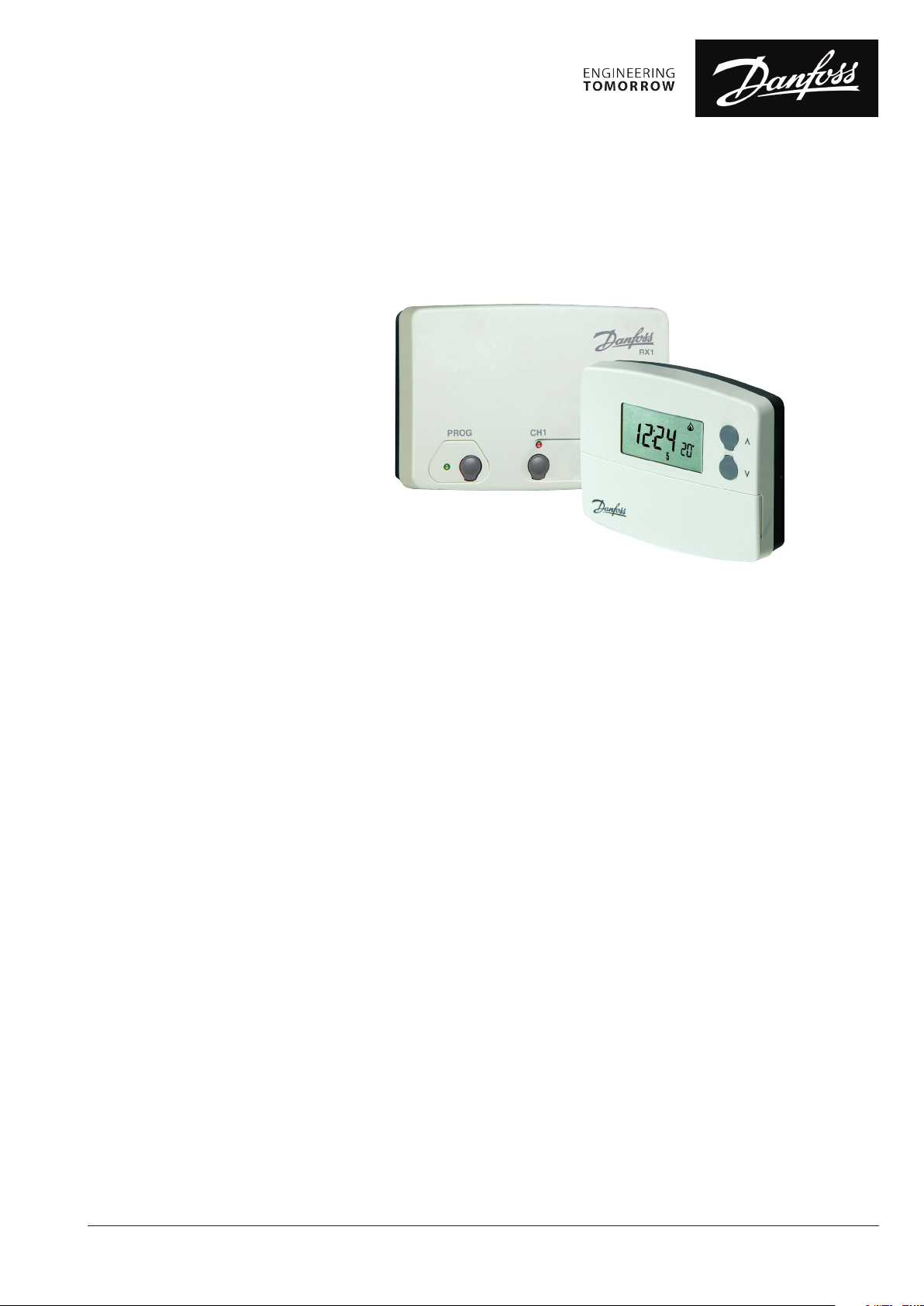
TP5001 Range
Programmable Room Thermostat
Features
The TP5001 is a microprocessor based
programmable room thermostat with many
advanced features. The range includes battery
and 230 volt powered hard-wired models and
battery powered wireless versions. All models
in the range utilise an advanced PI algorithm to
provide close and accurate temperature control to
reduce energy waste and ensure comfort under all
load conditions.
The TP5001 incorporates a factory set real time
clock, both date and time are set in the factory to
the appropriate time zone, eliminating the need
to set the time at installation or to change the
time in spring or autumn. This function is powered
from a separate lithium battery which lasts for the
lifetime of the product.
The calendar clock is also used to provide a service
due timer function which can be enabled by the
installer if required. If enabled, several operating
options are available ranging from audible & visual
service due warning to proportional reduction of
heating until the boiler is serviced and the service
due feature is reset by the installer.
The TP5001 is a 5-day / 2-day programmable
thermostat which also includes a feature which
allows two blocks of programmes to be set up
(A/B Programming), either programme can then
be assigned to any day of the week allowing the
programming to closer match the lifestyle of the
consumer, all without the need to go for a far
more complex 7-day unit.
Unlike earlier models, the TP5001 can be
congured by the installer to provide 2, 4 or 6
events per day, it can also be set up to provide
constant temperature control if required, again
this allows the thermostat to be matched with
consumers lifestyle.
Versions with programmable remote inputs are
also available. Remote inputs can be either remote
temperature sensing, (control or limit), or digital
inputs from window contacts, telephone operated
switches, card readers or building automation
systems.
For standard applications the product can be
installed and will work straight out of the box,
however there is a wide range of user and installer
options which allow the product operation to
be tuned to the specication requirements of
the system. Some of these options are hardware
settings made by DIL switches, but the majority
are software settings made in one of two advanced
programming modes.
Settings made by the installer or the end user are
stored for the life of the product in a non-volatile
memory chip which does not require power. This
same storage technique allows customer specic
programmes to be established as factory defaults,
but is only available for larger projects.
Signicant eort has been made to make the
product as energy ecient as possible, this
includes improving both on/o performance and
chrono-proportional performance, charts on page
4 detail the relative performance of each mode.
Programming of the TP5001 is as simple as it has
always been, just ve buttons and an intuitive MMI
ensure that the product is no more complicated to
the user than previous models.
© Danfoss HS | 09/2015 | 084v05 VDRMA51M
1
Page 2
Datasheet TP5001 Programmable Room Thermostat
Keyboard enabled
OFF
ON
Sw. N o.
Installer Hardware Settings
(Switches show factory setting)
1
Keyboard disabled
Reset disabled Reset enabled
2
Installer Advanced
Programming Settings
Option Description Factory Setting Other Setting
User Advanced Programming Options Use + or - key to scroll between options, use Λ or V keys to select option setting
1 Enable/disable A/B block programming 0 Disabled 1 Enabled
3 Automatic summer/winter time change 2 European rules
Time zone oset - UST models 00:00 Use UST clock setting ± 12 Hours oset from UST
4
Time zone oset - CET models 00:00 Use CET clock setting ± 12 Hours oset from CET
10 Set frost protection default temperature 8°C 5-30°C
11 Start-up type 0 Fixed time start-up
Optimum start control setting, maximum
pre-heat period based upon 2°C deviation
12
from next event temperature.
(Only accessible if option 11 is set to 2)
OSC or delay start function active
13
(Only accessible if option 11 is set to 1 or 2)
Option Description Factory Setting Other Setting
Installer Advanced Programming Options Use + or - key to scroll between options, use Λ or V keys to select option setting
30 Set range upper limit 30°C 40-50°C
31 Set range lower limit 5°C 5-40°C
32 Enable/disable O function at lower limit 0 Enabled 1 Disabled
33 Enable/disable On function at upper limit 0 Disabled 1 Enabled
34 Set chrono-proportional cycle rate 6 6 cycles per hour
35 Set integration time 2.5 2.50%
36 Set temperature override limit 0 No limit
37 Set time duration of override 0 Next event
38 Relay park status on battery low volt detect 0 Relay parked O 1 Relay parked On
40 Number of Events 6 6 Switching events per day
41 Operating Mode 5-2 5/2 day programming 24 24 Hour programming
70 Keyboard lock type 0 Normal Lock 1 Full lock
Random time on start-up (not battery
71
models)
72 Site ID number (user dened) 00 01 to 99
73 Thermostat ID number (user dened) 00 001 to 999
74 Date format for calendar clock 0 European (dd/mm/yy) 1 North American (mm/dd/yy)
81 Thermostat calibration bias 0 ±1.5K
Remote sensor conguration
90
(A models only)
Limit sensor set point adjustment
93
(Only accessible if Option 90 is set to 2)
Start-up (digital input) NO or NC
94
(Only accessible if Option 90 is set to 3)
1:00 60 minutes
0 First event of day only 1 All events
0 Disabled 1 Enabled
0 0, Disabled
27°C 20-50°C
NC, open circuit to change
0
to thermostat mode
0 Disabled
1 Manual time change
3 USA rules, post 2006
4 USA rules. pre-2007
1 Optimum start control
2 Delayed start-up
0:15 15 minutes
0:30 30 minutes
0:45 45 minutes
1:15 75 minutes
1:30 90 minutes
1:45 105 minutes
2:00 120 minutes
3 3 cycles per hour
9 9 cycles per hour
12 12 cycles per hour
5 5%
10 10%
1 Limited to ±2°C
2 Disabled, no override
1 1 hour
2 2 hours
3 3 hours
4 4 hours
1 Thermostat mode
2 2 Switching events per day
4 4 Switching events per day
1 Room/duct
2 Limit, (oor)
3 Start-up (digital input)
NO, close circuit to change to
1
thermostat mode
2
© Danfoss HS | 09/2015 | 084v05 VDRMA51M
Page 3

Datasheet
ErP
4
TP5001 Programmable Room Thermostat
Service Interval Timer
Specication and Ordering
The Service interval timer allows the installer to
select a service due date for the boiler, this can
be set at between 28 days and 366 days from the
current date.
Service due date is reached or passed
When the service due date is reached the visual
and audible warning are repeated each hour of
the day commencing at midday, but the duration
of the alarm is increased to 60 seconds, this can
Service due date is within 28 days
From 28 days prior to the service due date, a visual
warning will appear in the display and a buzzer will
sound for ten seconds each hour commencing at
midday, this can be cancelled for the current day
be cancelled for the current day by pressing any
button. All override and programming buttons
are disabled and depending upon service interval
timer setting, heating can be restricted to 15, 30 or
45 minutes in each programmed hour.
by pressing any button.
Option Service Interval Timer Function
Setting 0 Disabled, (factory default)
Setting 1 Active, visual and audible warning, no heat reduction
Setting 2 Active, visual and audible warning, heat reduced to 45 minutes per hour
Setting 3 Active, visual and audible warning, heat reduced to 30 minutes per hour
Setting 4 Active, visual and audible warning, heat reduced to 15 minutes per hour
Thermostat Features
Hard-wired, built-in sensor
Hard-wired, remote sensor inputs
Wireless, built-in sensor
Wireless, built-in sensor complete
with RX1 receiver
Wireless, remote sensor
5/2 day or 24 hour programmable room thermostat Yes, selectable by installer
2, 4 or 6 events per day with optional A/B programming Yes, selectable by installer
Factory pre-set programmes Yes, one for weekdays, another for weekends
Factory set calendar clock Automatic summer/wintertime change
Time accuracy ± 1 minute per year
Memory back-up, time and all user and installer settings Retained for life of product
Temperature range 5-30°C
Programmable frost thermostat function Yes
Control output, derived from PI algorithm On/O or Chrono-proportional, 3, 6, 9 or 12 cycles per hour
Switching dierential in On/O mode ±1°C
Installer selectable advanced programming options Yes, refer to installation instructions for list
Installer selectable service interval timer Yes, 28 to 366 days from current date
Programmable range limitation Yes, max and min
Electronic keyboard lock Yes, full or part
Power Supply 2 x AA alkaline cells 230V, 50Hz
Switching action of output relay SPDT (voltage free)
Switch rating of output relay 3 (1) A, 10-230V N/A 3(1)A, 10-230V
Transmission frequency (RF models) N/A 433.92MHz N/A
Transmission range (RF models) N/A 30m max. N/A
Dimensions, mm 110 wide x 88 high x 28 deep
Design standard EN60730-2-9, (EN300220 for RF)
(1)
Can be congured by installer for remote temperature sensor, limit sensor, window contact or telephone activated switch contact.
(2)
Remote sensor is supplied as an accessory, if remote room sensor is required order TS2 sensor, code 087N681100
(3)
RX receiver requires 230 volt power supply
(3)
(1) (2)
Type
Sales Code
Type
Sales Code
Type
Sales Code
Type
Sales Code
Type
Sales Code
Battery Models 230V Models
Hard-wired Wireless Hard-wired
TP5001
087N791001
TP5001A
087N791101
TP5001RF
087N791201
TP5001RF + RX1
087N791401
TP5001ARF
087N791301
TP5001M
087N791701
TP5001MA
087N791801
ErP Class
Product
Class
ERP Class
The products represented within this document are classied according to, and allow completion of, the Energy Related Product
(ErP) Directive System Package che and the ErP system data label. ErP Labelling obligation is applicable from 26th September
2015.
ErP Class Product Function and ErP Description Additional eciency gain
IV
© Danfoss HS | 09/2015 | 084v05 VDRMA51M
TPI Room Thermostat, for use with on/off output heaters
An electronic room thermostat that controls both thermostat cycle rate
and in-cycle on/o ratio of the heater proportional to room temperature.
TPI control strategy reduces mean water temperature, improves room
temperature control accuracy and enhances system eciency.
2%
3
Page 4

Datasheet
1 ON
2 ON
10
11
12
13
14
15
16
17
18
19
20
21
22
0
1 2 3 4 5 6 7 8 9 10 11 12
Time (Hours)
Room Temperature (C)
10
11
12
13
14
15
16
17
18
19
20
21
22
0 1 2 3 4 5 6 7 8 9 10 11 12
Time (Hours)
Room Temperature (C)
TP5001 Programmable Room Thermostat
Wiring
TP5001
S1/D
S2/E
1 2 3
NC
OFF
NO
COM
Heating
Load
ON
Remote Input
(TP5001A and
TP5001MA only)
RX Receiver Wiring (RF Models)
RX1
RX2 & RX3
1) For mains voltage operated systems link terminal 2 to mains live supply.
2) Power supply to unit must not be switched by timeswitch.
ELECTRONICS
N L
ELECTRONICS
C 123 4 5
A
B
L
N
1 2
COM
3
4
ZONE
COM
ZONE
1 OFF
1 ON
TERMINAL 6
RX3 ONLY
6
ZONE
ZONE
ZONE
ZONE
1 OFF
3 ON
TP5001M
Electronics
B
C
N
N
L
L
Remote Input
(TP5000MA Si only)
Please note:
On230V version the power supply is connected to L and N.
1 2 3
NC
OFF
COM
NO
ON
Heating
Load
Remote Input Options
S1/D
S2/E
Congured for
remote room
sensor or limit
sensor
S1/D
S2/E
Window or
teleswitch
contact
(NO or NC)
Congured for
window contact or
other contact such
as teleswitch
S2
S1
E
D
S1/D
S2/E
Window
contact (NC)
Teleswitch
contact (NC)
Congured for
window contact
and other contact
such as teleswitch
Thermal Performance
On/O Control
Chrono-Proportional Control
Danfoss Randall Ltd.
Ampthill Road
Bedford MK42 9ER
Tel: 0845 1217 400
Fax: 0845 1217 515
Email: danfossrandall@danfoss.com
Website: www.danfoss-randall.co.uk
Danfoss can accept no responsibility for possible errors in catalogues, brochures, and other printed material. Danfoss reserves the right to alter its products without notice. This also applies to products already
on order provided that such alterations can be made without subsequent changes being necessary in specifications already agreed.
All trademarks in this material are property of the respective companies. Danfoss and the Danfoss logotype are trademarks of Danfoss A/S. All rights reserved.
4
© Danfoss HS | 09/2015 | 084v05 VDRMA51M
(Chrono 6)
 Loading...