

Page 1
Datasheet
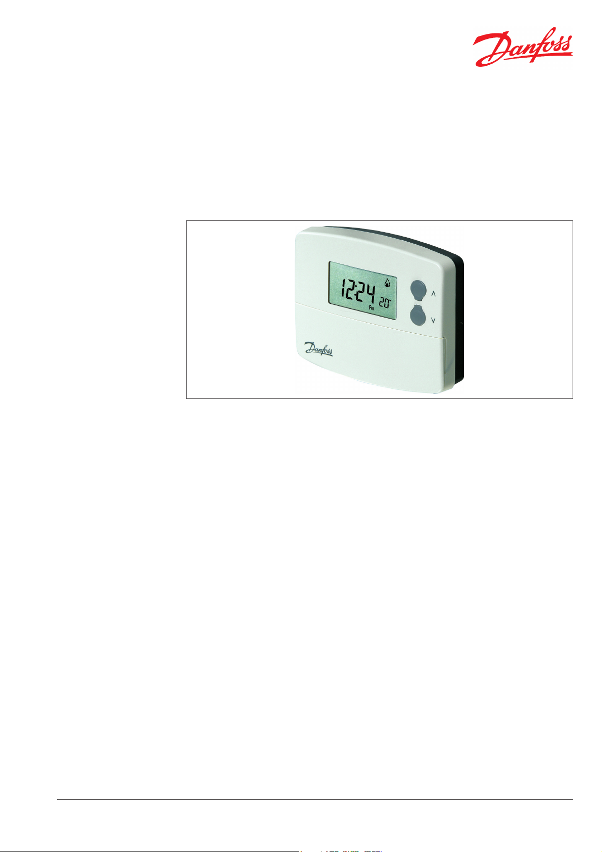
TP5000M Si
Programmable Room Thermostat
Features
The TP5000M Si is a microprocessor based
programmable room thermostat with many
advanced features. All models in the range
utilise an advanced PI algorithm to provide close
and accurate temperature control to reduce
energy waste and ensure comfort under all load
conditions.
The TP5000M Si incorporates a factory set real time
clock, both date and time are set in the factory to
the appropriate time zone, eliminating the need
to set the time at installation or to change the
time in spring or autumn. This function is powered
from a separate lithium battery which lasts for the
lifetime of the product.
The calendar clock is also used to provide a service
due timer function which can be enabled by the
installer if required. If enabled, several operating
options are available ranging from audible & visual
service due warning to proportional reduction of
heating until the boiler is serviced and the service
due feature is reset by the installer.
The TP5000M Si is a 5-day / 2-day programmable
thermostat which also includes a feature which
allows two blocks of programmes to be set up
(A/B Programming), either programme can then
be assigned to any day of the week allowing the
programming to closer match the lifestyle of the
consumer, all without the need to go for a far
more complex 7-day unit.
this allows the thermostat to be matched with
consumers lifestyle.
Versions with programmable remote inputs are
also available. Remote inputs can be either remote
temperature sensing, (control or limit), or digital
inputs from window contacts, telephone operated
switches, card readers or building automation
systems.
For standard applications the product can be
installed and will work straight out of the box,
however there is a wide range of user and installer
options which allow the product operation to
be tuned to the speci cation requirements of
the system. Some of these options are hardware
settings made by DIL switches, but the majority
are software settings made in one of two advanced
programming modes.
Settings made by the installer or the end user are
stored for the life of the product in a non-volatile
memory chip which does not require power. This
same storage technique allows customer speci c
programmes to be established as factory defaults,
but is only available for larger projects.
Signi cant e ort has been made to make the
product as energy e cient as possible, this
includes improving both on/o performance and
chrono-proportional performance, charts on page
4 detail the relative performance of each mode.
Unlike earlier models, the TP5000M Si can be
con gured by the installer to provide 2, 4 or 6
events per day, it can also be set up to provide
constant temperature control if required, again
Part No. 698v01 08/07
Programming of the TP5000M Si is as simple
as it has always been, just ve buttons and an
intuitive MMI ensure that the product is no more
complicated to the user than previous models.
1
Page 2
Datasheet TP5000M Si Programmable Room Thermostat
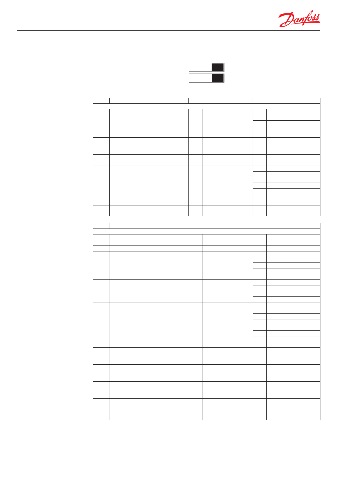
Installer Hardware Settings
(Switches show factory setting)
Installer Advanced
Programming Settings
Sw. No.
Keyboard disabled
1
Reset disabled Reset enabled
2
Option Description Factory Setting Other Setting
User Advanced Programming Options Use + or - key to scroll between options, use Λ or V keys to select option setting
1 Enable/disable A/B block programming 0 Disabled 1 Enabled
3 Automatic summer/winter time change 2 European rules
Time zone o set - UST models 00:00 Use UST clock setting ± 12 Hours o set from UST
4
Time zone o set - CET models 00:00 Use CET clock setting ± 12 Hours o set from CET
10 Set frost protection default temperature 5°C 5-30°C
11 Start-up method 0 Fixed time start-up
Optimum start control setting, maximum
pre-heat period based upon 2°C deviation
12
from next event temperature.
(Only accessible if option 11 is set to 2)
OSC or delay start function active
13
(Only accessible if option 11 is set to 1 or 2)
Option Description Factory Setting Other Setting
Installer Advanced Programming Options Use + or - key to scroll between options, use Λ or V keys to select option setting
30 Set range upper limit 30°C 40-50°C
31 Set range lower limit 5°C 5-40°C
32 Enable/disable O function at lower limit 1 Enabled 0 Disabled
33 Enable/disable On function at upper limit 0 Disabled 1 Enabled
34 Set chrono-proportional cycle rate 3 3 cycles per hour
35 Set integration time 2.5 2.50%
36 Set temperature override limit 0 No limit
37 Set time duration of override 0 Next event
40 Number of Events 6 6 switching events per day
41 Operating Mode 5-2 5/2 day programming 24 24 hour programming
70 Keyboard lock type 0 Normal Lock 1 Full lock
71 Random time on start-up 0 Disabled 1 Enabled
72 Site ID number (user de ned) 00 01 to 99
73 Thermostat ID number (user de ned) 00 001 to 999
74 Date format for calendar clock 0 European (dd/mm/yy) 1 North American (mm/dd/yy)
81 Thermostat calibration bias 0 ±1.5K
Remote sensor con guration
90
(A models only)
Limit sensor set point adjustment
93
(Only accessible if Option 90 is set to 2)
Start-up (digital input) NO or NC
94
(Only accessible if Option 90 is set to 3)
OFF
ON
Keyboard enabled
0:15 15 minutes
0 First event of day only 1 All events
0 0, Disabled
27°C 20-50°C
NC, open circuit to change
0
to thermostat mode
0 Disabled
1 Manual time change
3 USA rules, post 2006
4 USA rules. pre-2007
1 Optimum start control
2 Delayed start-up
0:30 30 minutes
0:45 45 minutes
1:00 60 minutes
1:15 75 minutes
1:30 90 minutes
1:45 105 minutes
2:00 120 minutes
0 On/O
6 6 cycles per hour
9 9 cycles per hour
12 12 cycles per hour
55%
10 10%
1 Limited to ±2°C
2 Disabled, no override
1 1 hour
2 2 hours
3 3 hours
4 4 hours
1 Thermostat mode
2 2 switching events per day
4 4 switching events per day
1 Room/duct
2 Limit, ( oor)
3 Start-up (digital input)
NO, close circuit to change to
1
thermostat mode
2
Part No. 698v01 08/07
Page 3

Datasheet
TP5000M Si Programmable Room Thermostat
Service Interval Timer Service due date is reached or passed
The service interval timer allows the installer to
select a service due date for the boiler, this can
be set at between 28 days and 366 days from the
current date.
When the service due date is reached the visual
and audible warning are repeated each hour of
the day commencing at midday, but the duration
of the alarm is increased to 60 seconds, this can
Service due date is within 28 days
From 28 days prior to the service due date, a visual
warning will appear in the display and a buzzer will
sound for ten seconds each hour commencing at
midday, this can be cancelled for the current day
be cancelled for the current day by pressing any
button. All override and programming buttons
are disabled and depending upon service interval
timer setting, heating can be restricted to 15, 30 or
45 minutes in each programmed hour.
by pressing any button.
Option Service Interval Timer Function
Setting 0 Disabled, (factory default)
Setting 1 Active, visual and audible warning, no heat reduction
Setting 2 Active, visual and audible warning, heat reduced to 45 minutes per hour
Setting 3 Active, visual and audible warning, heat reduced to 30 minutes per hour
Setting 4 Active, visual and audible warning, heat reduced to 15 minutes per hour
Speci cation and Ordering
Thermostat Features
Hard-wired, built-in sensor
Hard-wired, remote sensor inputs
5/2 day or 24 hour programmable room thermostat Yes, selectable by installer
2, 4 or 6 events per day with optional A/B programming Yes, selectable by installer
Factory pre-set programmes Yes, one for weekdays, another for weekends
Factory set calendar clock Automatic summer/wintertime change
Time accuracy ± 1 minute per year
Memory back-up, time and all user and installer settings Retained for life of product
Temperature range 5-30°C
Programmable frost thermostat function Yes
Control output, derived from PI algorithm On/O or Chrono-proportional, 3, 6, 9 or 12 cycles per hour
Switching di erential in On/O mode ±1°C
Installer selectable advanced programming options Yes, refer to installation instructions for list
Installer selectable service interval timer Yes, 28 to 366 days from current date
Programmable range limitation Yes, max and min
Electronic keyboard lock Yes, full or part
Power supply 230V, 50Hz
Switching action of output relay SPDT (voltage free)
Switch rating of output relay 3 (1) A, 10-230V
Dimensions, mm 110 wide x 88 high x 28 deep
Design standard EN60730-2-9
(1)
Can be con gured by installer for remote temperature sensor, limit sensor, window contact or telephone activated switch contact.
(2)
Remote sensor is supplied as an accessory, if remote room sensor is required order TS2 sensor, code 087N681100.
(1) (2)
Type
Sales Code
Type
Sales Code
230V models
Hard-wired
TP5000M Si
087N791700
TP5000MA Si
087N791800
Part No. 698v01 08/07
3
Page 4

Datasheet
2
)
2
TP5000M Si Programmable Room Thermostat
Wiring
TP5000M Si
Electronics
C
N
L
123
NC
OFF
COM
NO
B
N
ON
Heating
Load
Please note:
On 230V version the power supply is connected to L and N.
On the 24V version the power supply is connected to A and B.
Remote Input Options
S1
S2
S1
S2
Window or
teleswitch
contact
(NO or NC)
S1
S2
Window
contact (NC)
Teleswitch
contact (NC)
S1
S2
S1LS2
Remote Input
(TP5000MA Si only)
Remote Input
(TP5000MA Si only)
Con gured for
remote room
sensor or limit
sensor
Thermal Performance
Danfoss can accept no responsibility for possible errors in catalogues, brochures, and other printed material. Danfoss reserves the right to alter its products without notice. This also applies to products already
on order provided that such alterations can be made without subsequent changes being necessary in specifications already agreed.
All trademarks in this material are property of the respective companies. Danfoss and the Danfoss logotype are trademarks of Danfoss A/S. All rights reserved.
22
21
20
19
18
17
16
15
Room Temperature (C)
14
13
12
11
10
012345678910111
Con gured for
window contact or
other contact such
as teleswitch
Time (Hours
Con gured for
window contact
and other contact
such as teleswitch
On/O Con trol
22
21
20
19
18
17
16
15
Room Temperature (C)
14
13
12
11
10
012345678910111
Chrono-Proportional Control
Time (Hours)
(Chrono 6)
Danfoss Randall Ltd.
Ampthill Road
Bedford MK42 9ER
Tel: 0845 1217 400
Fax: 0845 1217 515
Email: danfossrandall@danfoss.com
Website: www.danfoss-randall.co.uk
4
Part No. 698v01 08/07
 Loading...