

Page 1
MAKING MODERN LIVING POSSIBLE
Danfoss Heating
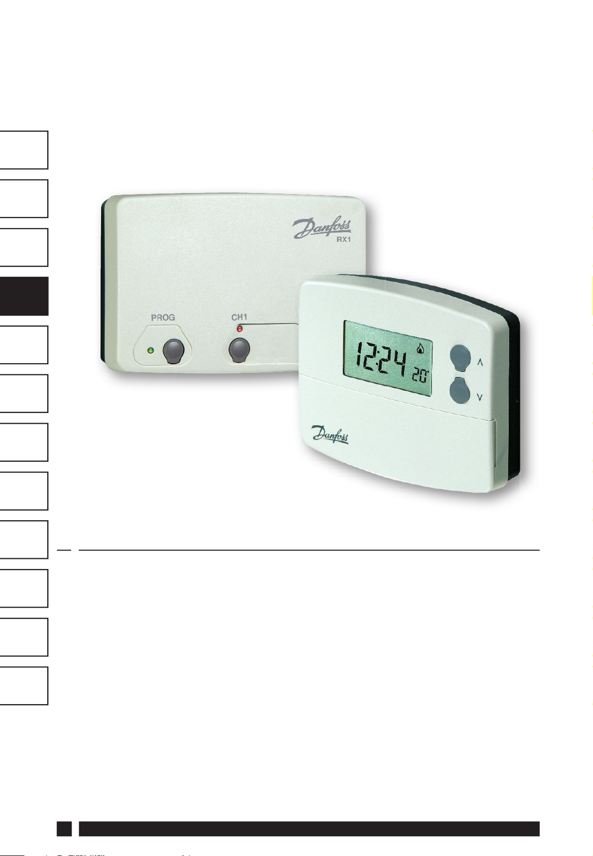
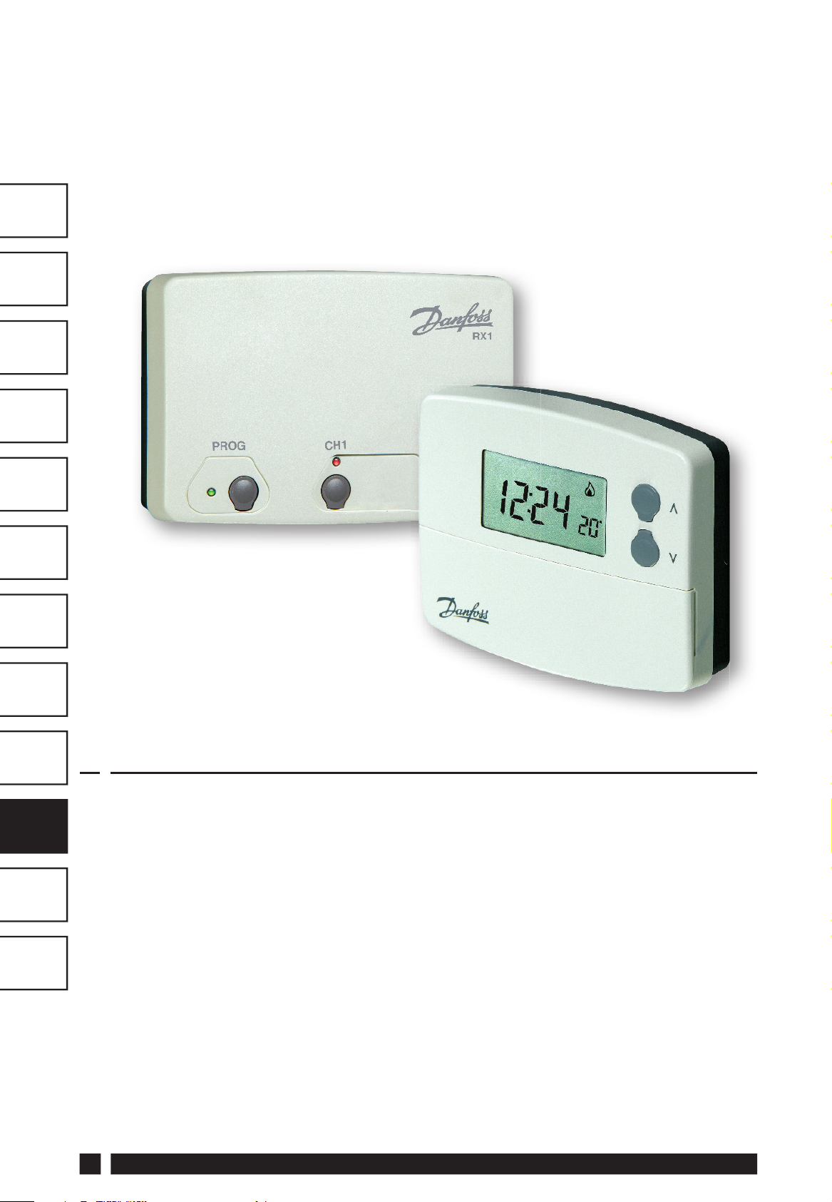
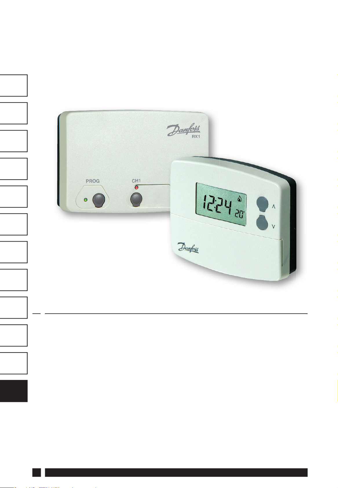
TP4000 Range
Electronic programmable room thermostat
Installation Guide
Page 2

For a large print version of these instructions
please call Marketing on 0845 121 7400.
®
Certification Mark
Danfoss can accept no responsibility for possible errors in catalogues, brochures, and other
printed material. All trademarks in this material are property of the respective companies.
Danfoss and the Danfoss logotype are trademarks of Danfoss A/S. All rights reserved.
2
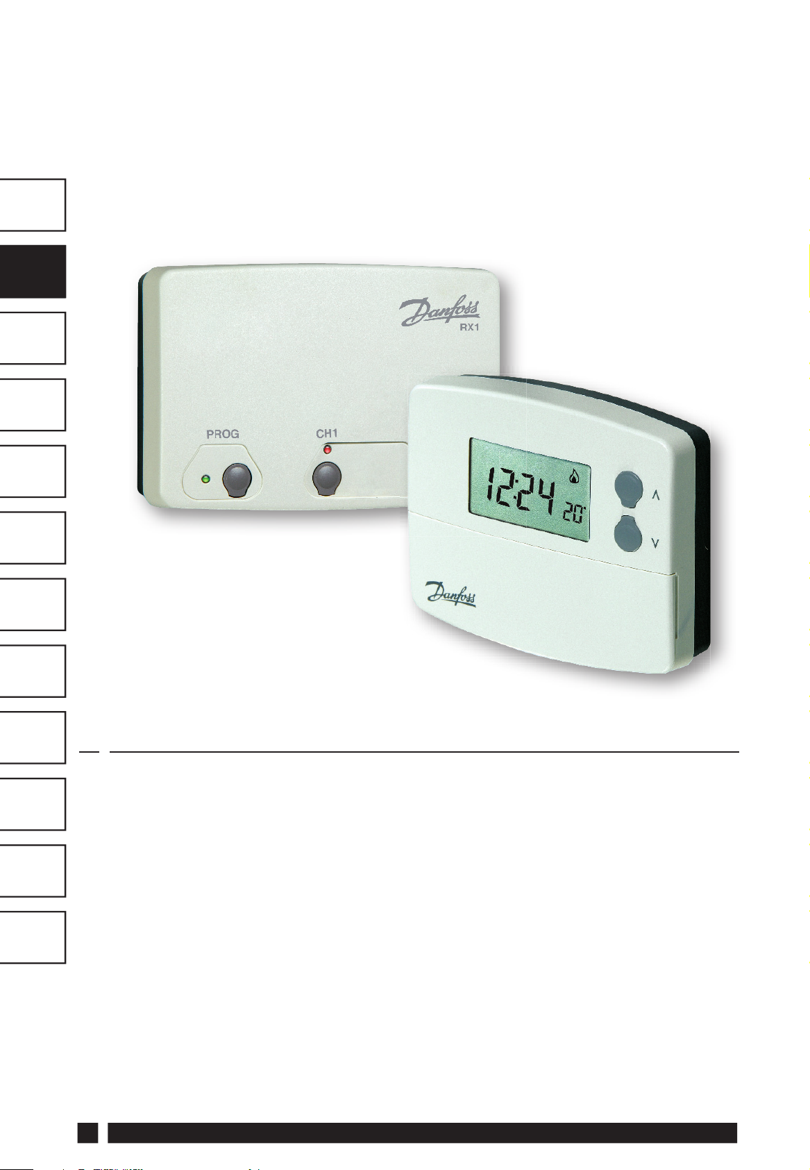
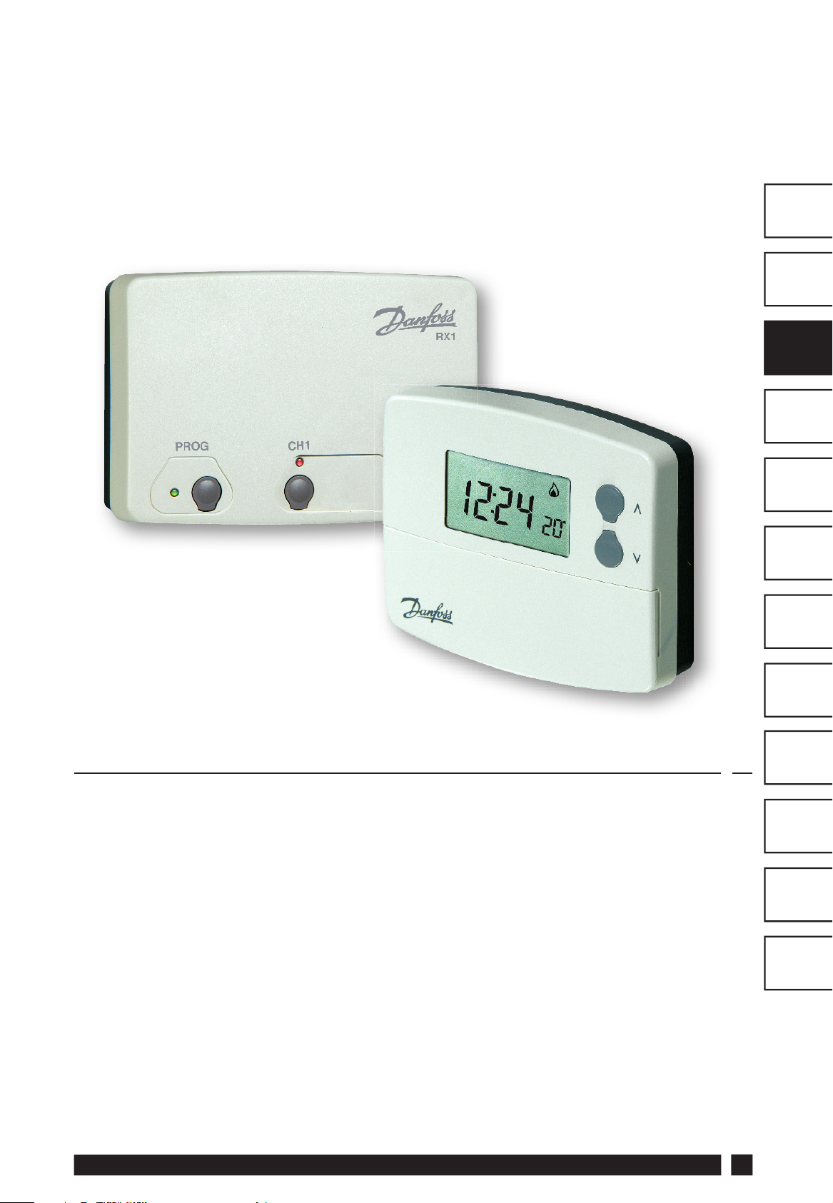
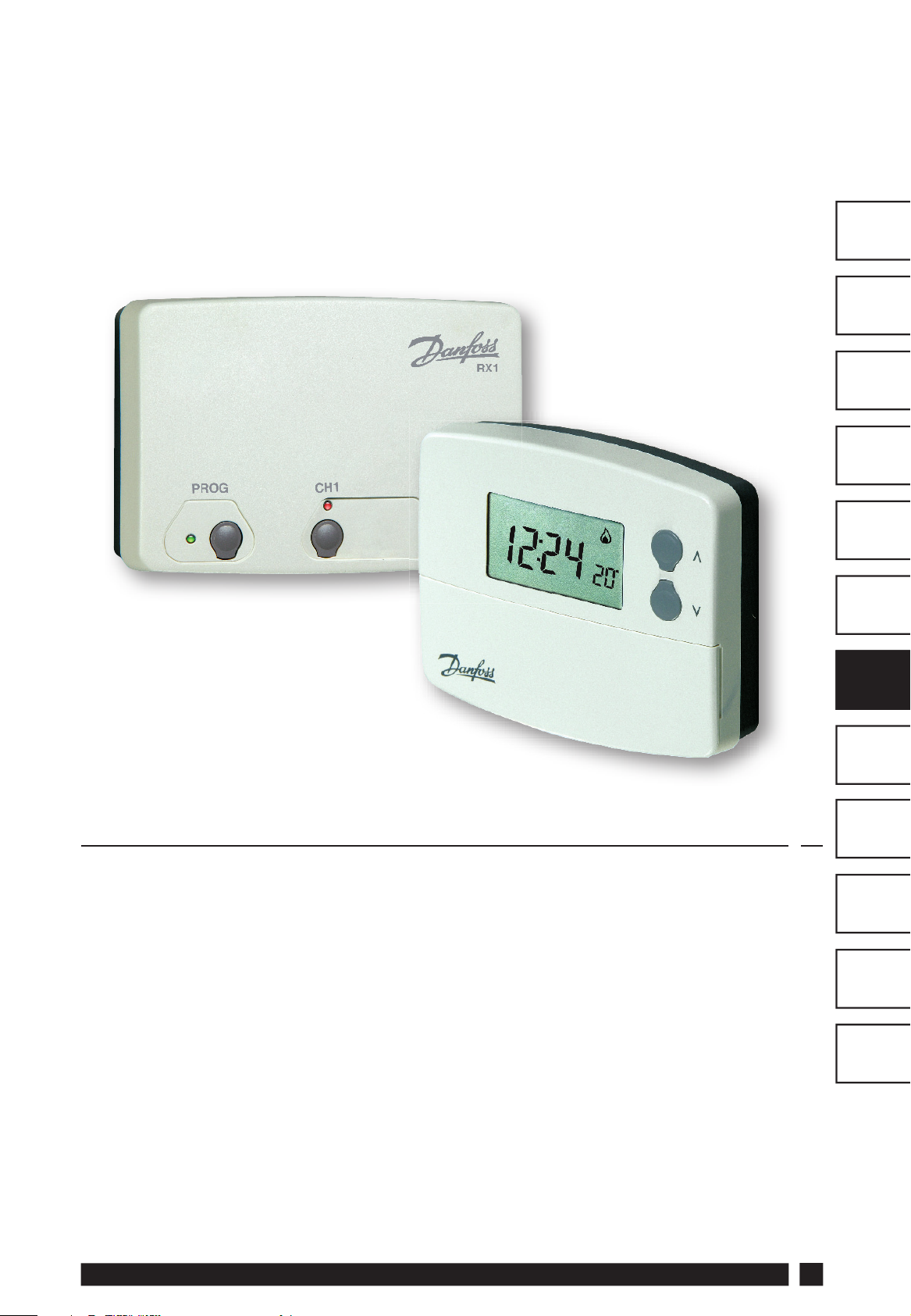
TP4000
Page 3
TP4000 Range
Electronic Programmable Room Thermostat
Installation Guide
GB
GB
FR
ES
NL
GR
PL
Index
1.0 Product Specifi cation.........................................................................4
2.0 Installation ..............................................................................................5
2.1 Thermostat Wiring (Hard wired model only) ........................5
2.2 RX Receiver Wiring (RF models only) ......................................6
3.0 Commissioning (RF models only) ................................................6
4.0 TP4000/TP4000 RF Programming ...............................................7
CZ
TR
HR
RO
HU
LT
Danfoss Heating
3
Page 4
GB
GB
FR
ES
Please Note:
This product should only be installed by a qualifi ed
electrician or competent heating installer and should
be in accordance with the current edition of the IEEE
wiring regulations.
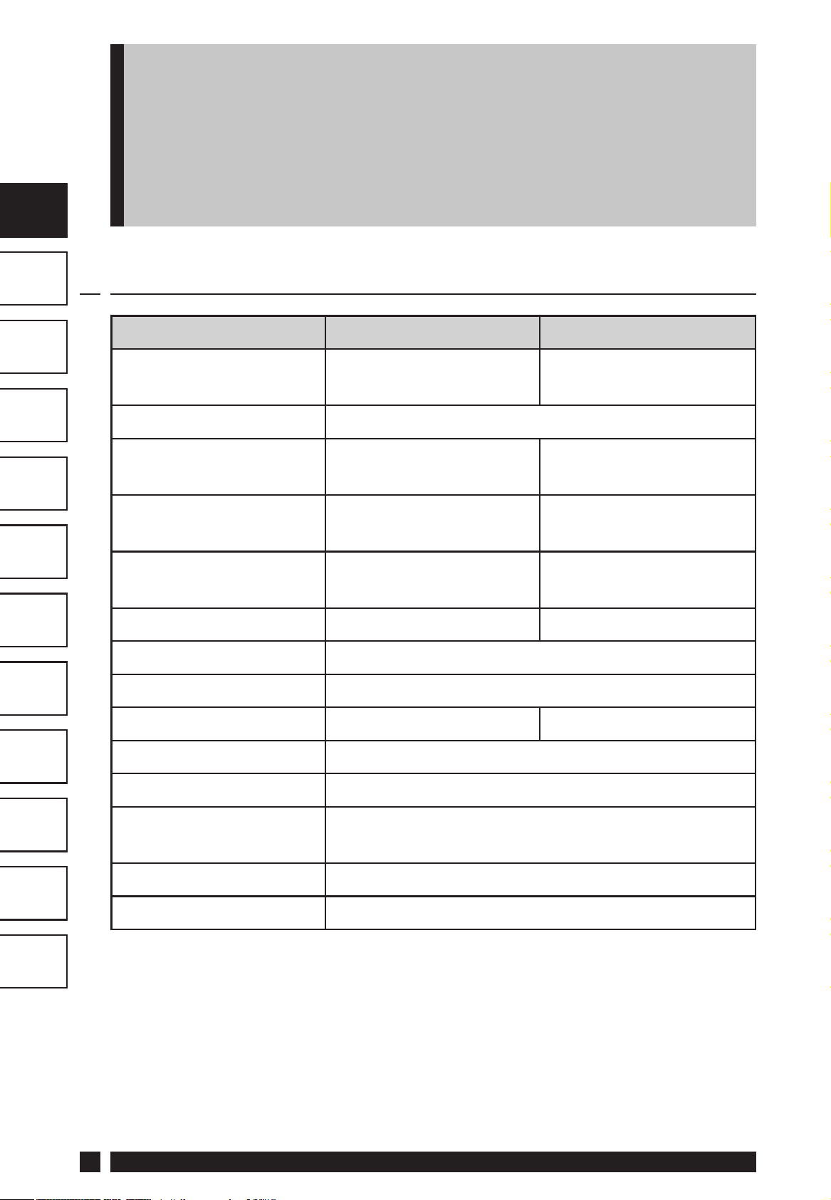
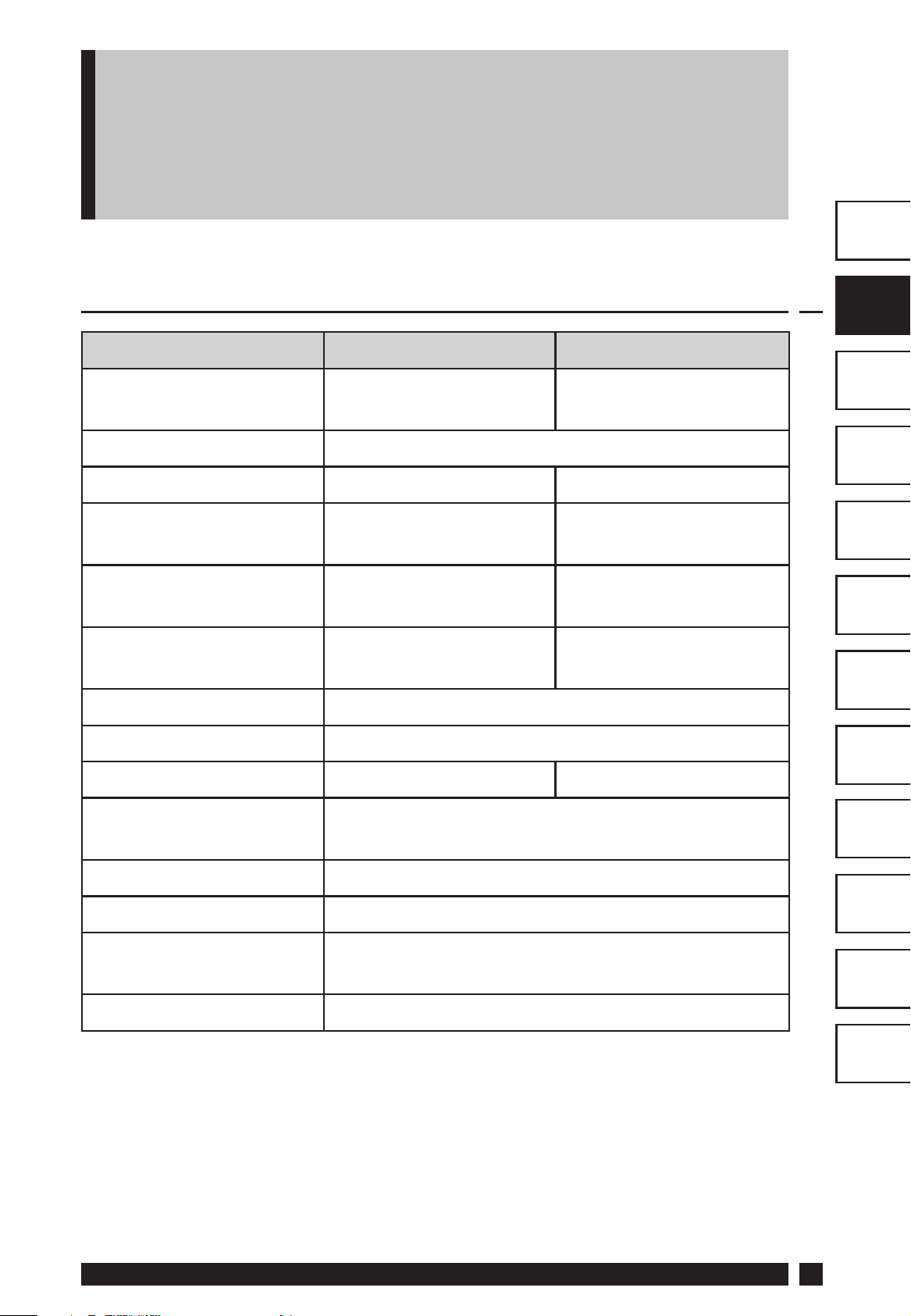
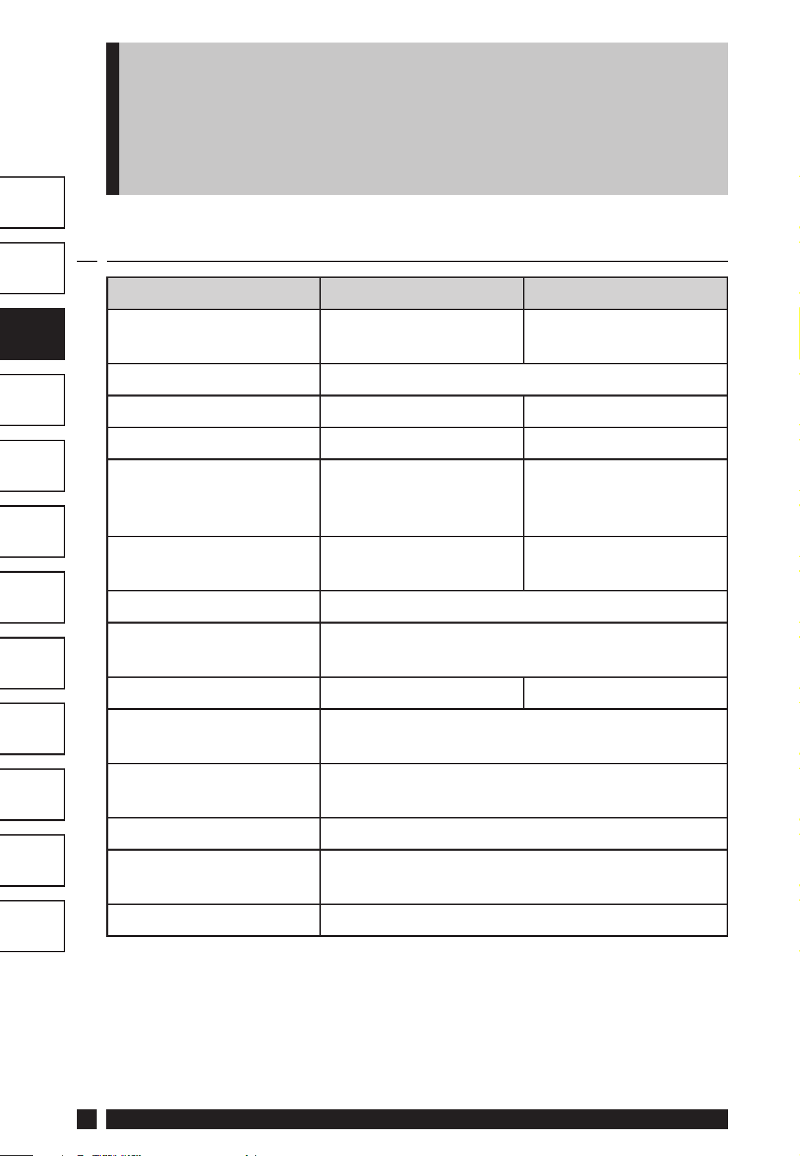
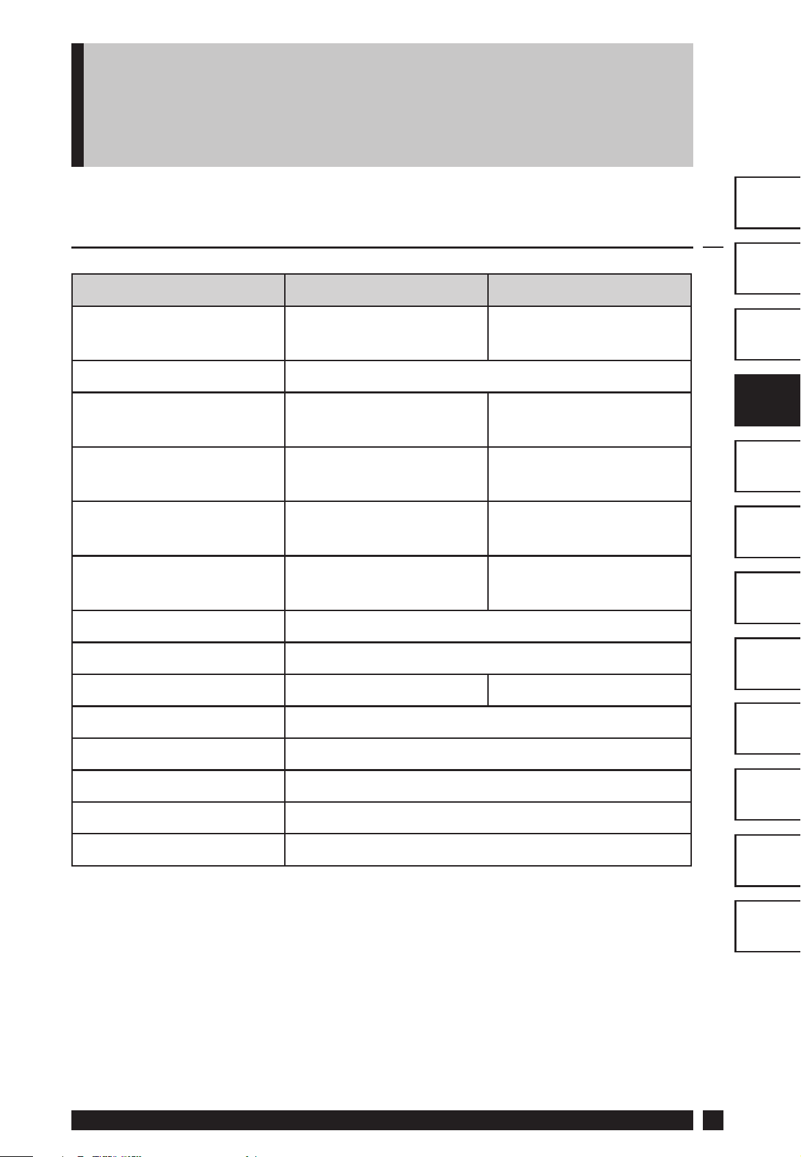
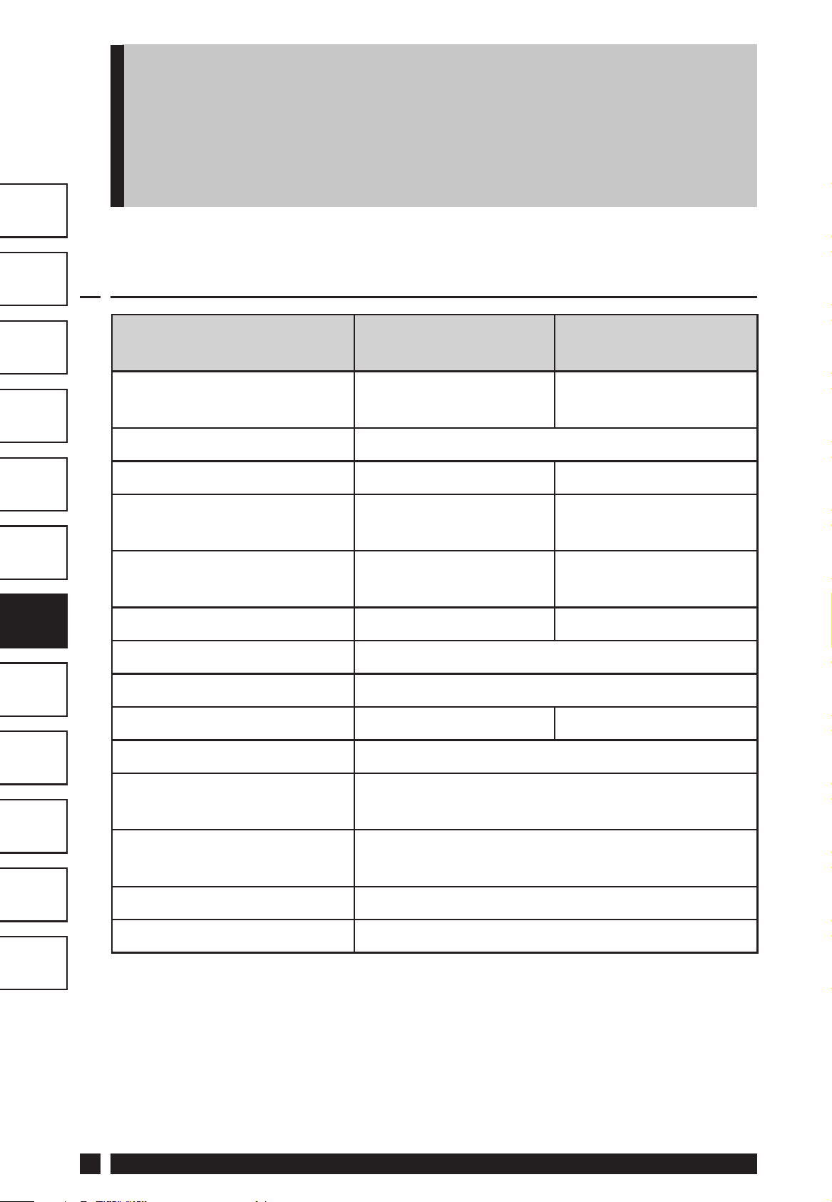
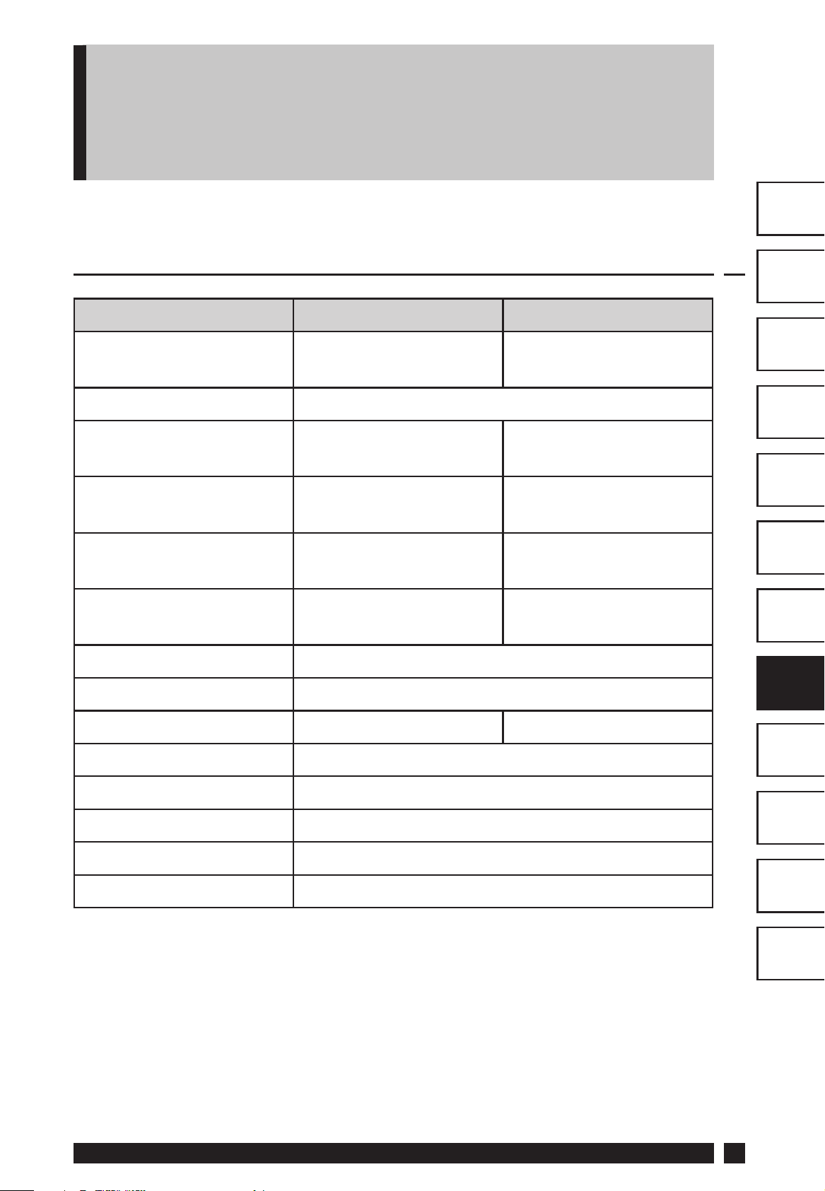
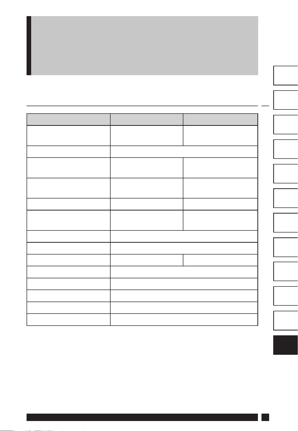
1.0 Product Specifi cation
Thermostat features TP4000 TP4000 RF
Power supply 2 x AA/MN1500/LR
alkaline cells
2 x AA/MN1500/LR
alkaline cells
NL
GR
PL
CZ
TR
HR
RO
Memory back-up 1 min for battery change
Switching action of
output relay
Switch rating of relay
contact
Transmission frequency
(RF Models)
Transmission range 30m max
Temperature range Off , 5-30°C
Dimensions, mm 110 wide, 88 high, 28 deep
Design standard EN60730-2-9 EN300220
Rated impulse voltage 2.5kV
Ball hardness test 75°C
Control pollution
situation
1 x SPDT, Type 1B N/A
3(1)A, 10-230Vac N/A
433.92MHz
Degree 2
HU
LT
Temperature accuracy ±1°C
Time accuracy ±1 min. per month
Important note RF products: Ensure that there are no large metal
objects, such as boiler cases or other large appliances, in line of
sight between the transmitter and receiver as these will prevent
communication between thermostat and receiver.
4
TP4000
Page 5
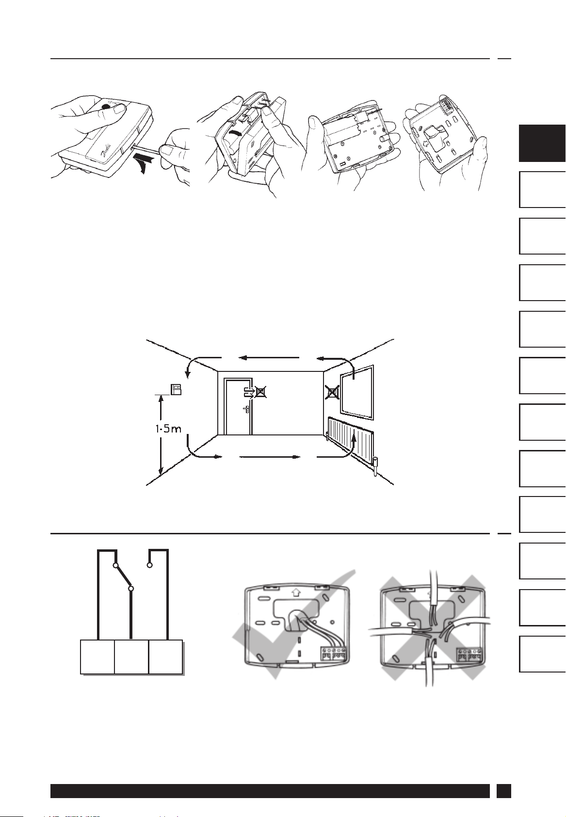
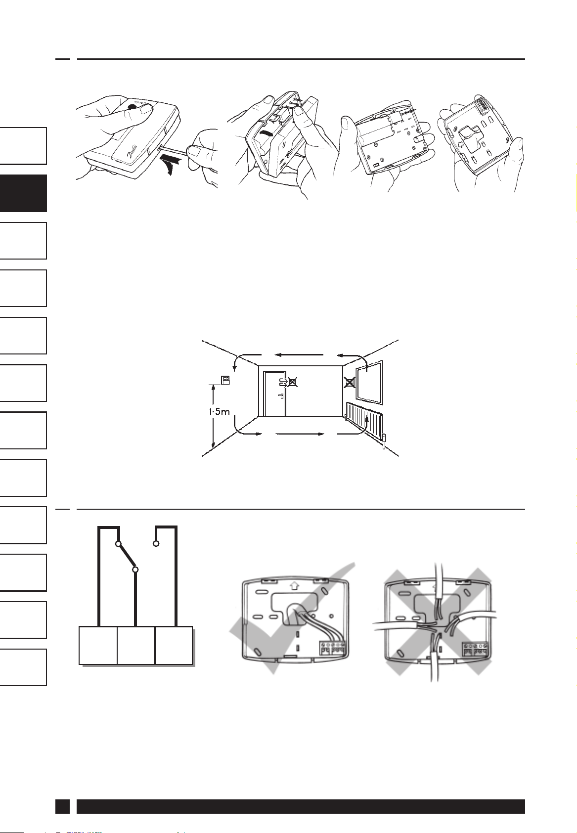
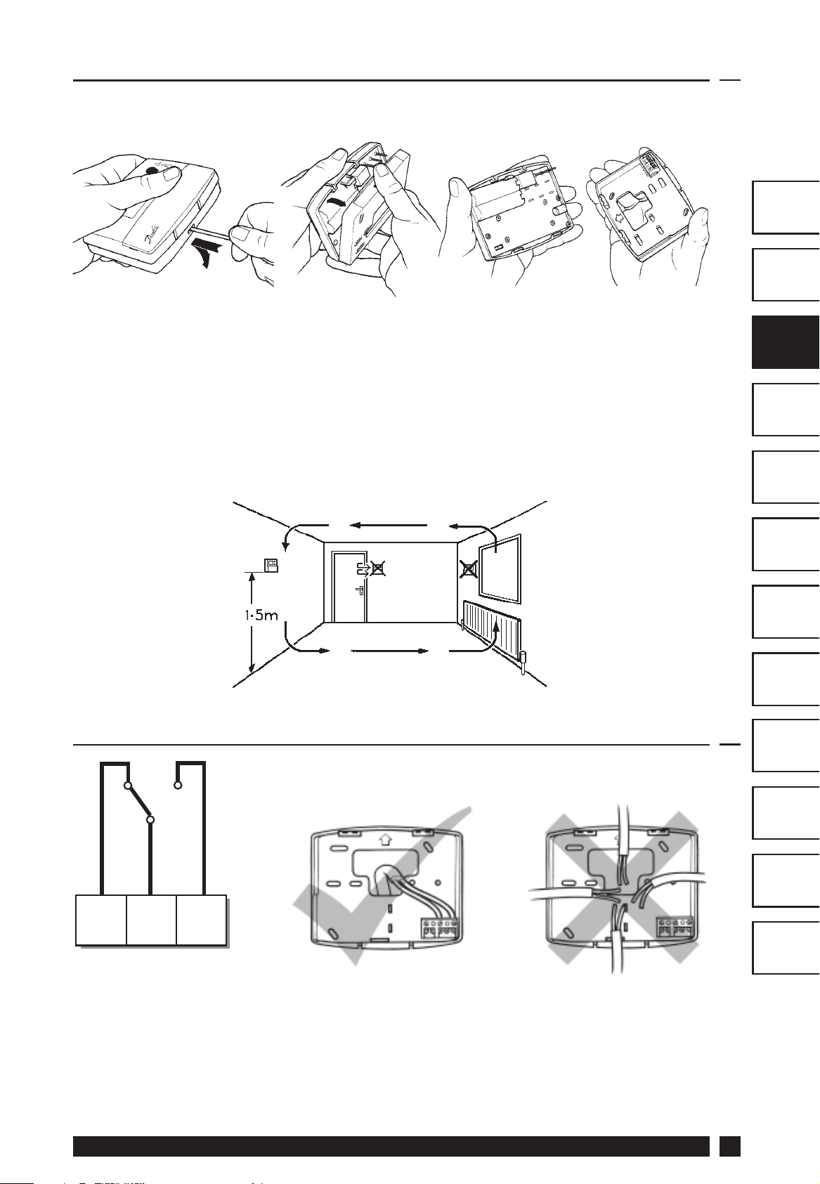
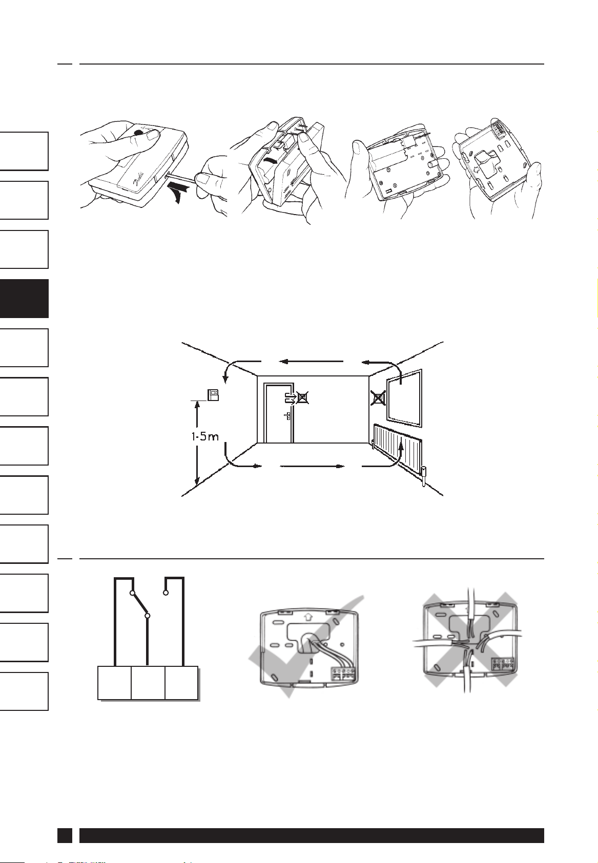
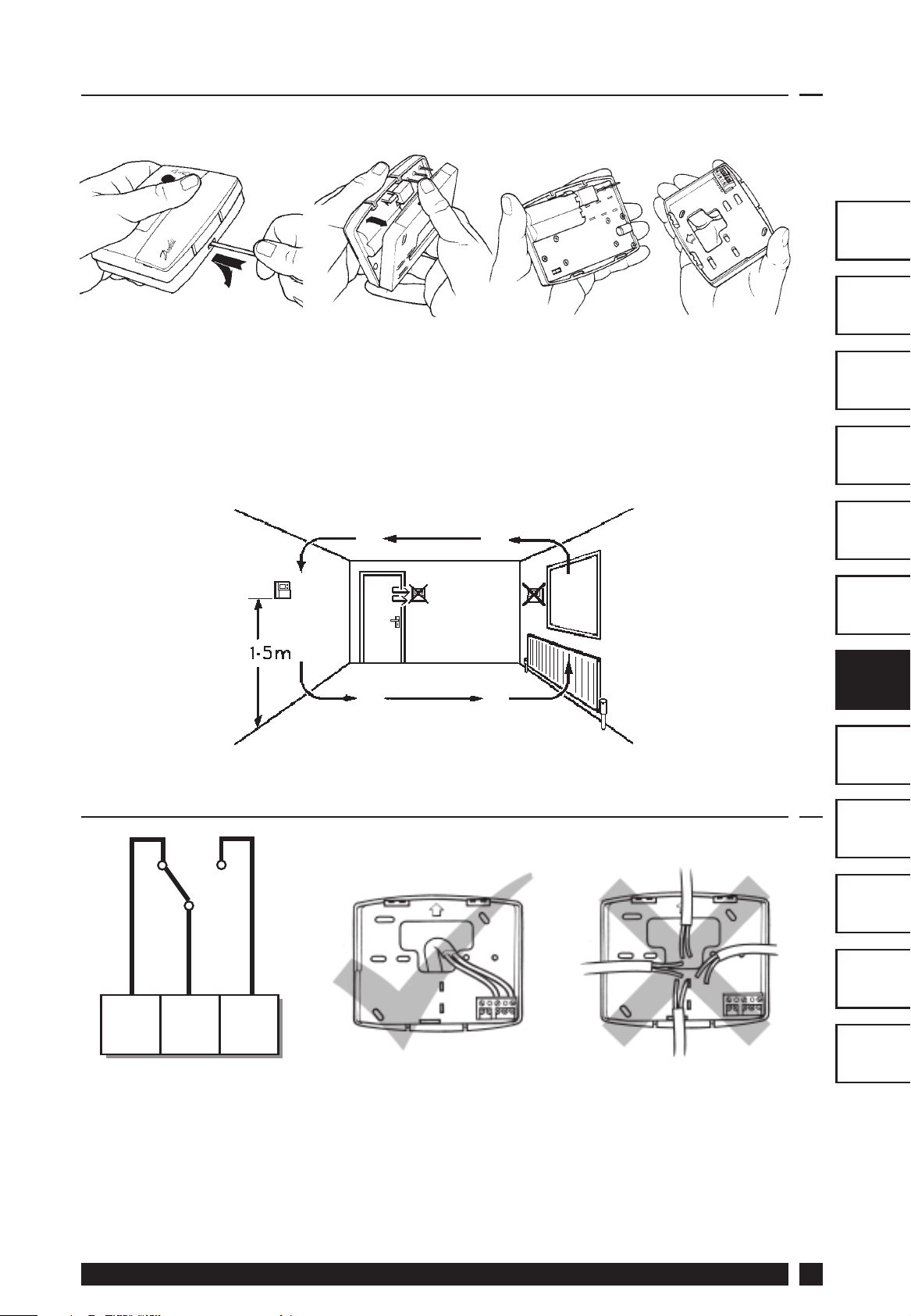
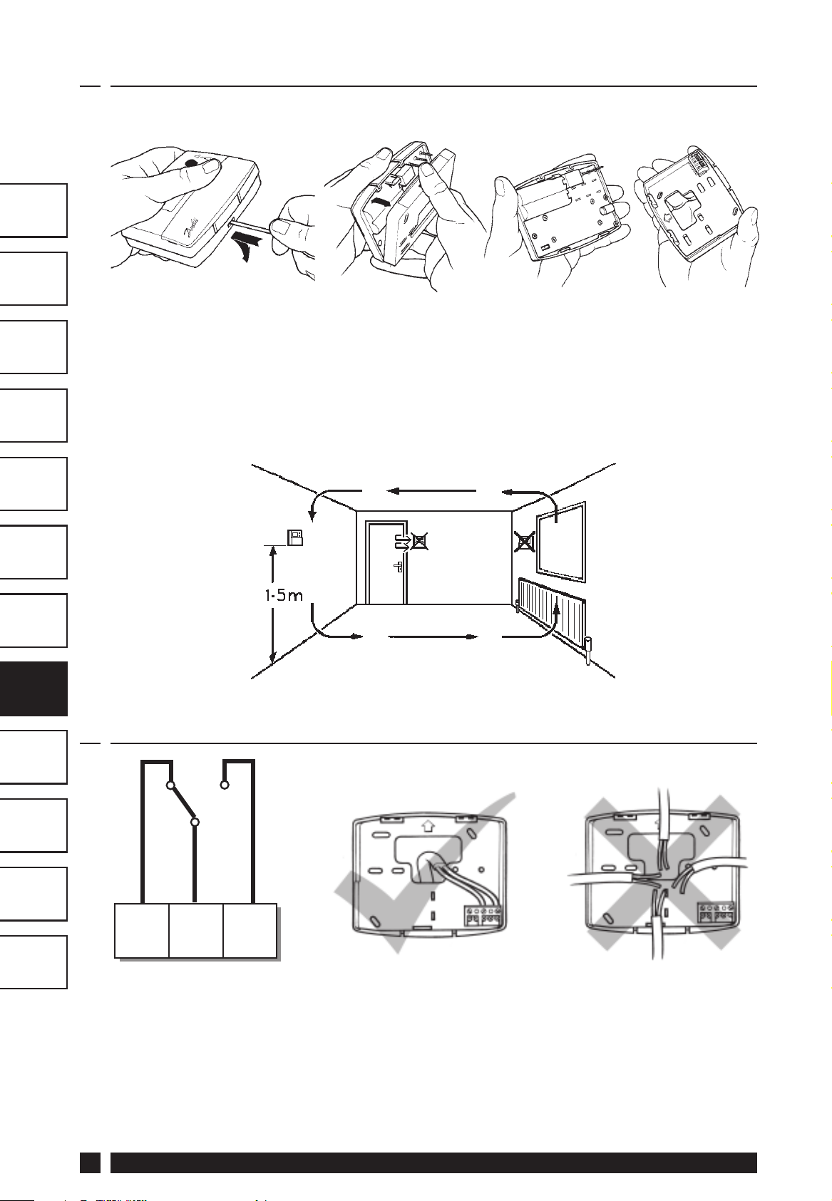
2.0 Installation
· First, remove the wallplate from the back of the unit.
· From the top left hand corner of the wallplate, there must be
clearances of at least 150mm to the right, 15mm to the left,
30mm above and 100mm below in order to mount the plug-in
module.
GB
GB
FR
ES
· Fix at a height of approximately 1.5m from the fl oor, away from
draughts or heat sources such as radiators, open fi res or direct
sunlight.
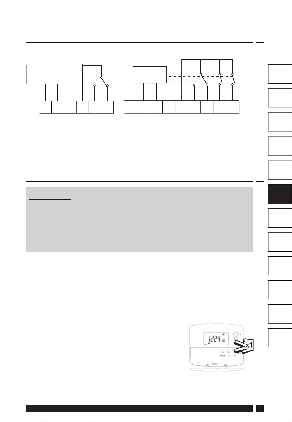
2.1 Thermostat Wiring (Hard wired model only)
NL
GR
PL
CZ
TR
HR
N/C
1
OFF
Some existing thermostats will have a Neutral and/or Earth wire
connected. These are not required by the TP4000 and must NOT be
connected to any TP4000 terminals. Instead they should be made
!
electrically safe and coiled in the recess at the back of the TP4000.
Danfoss Heating
N/O
23
COM ON
RO
HU
LT
5
Page 6
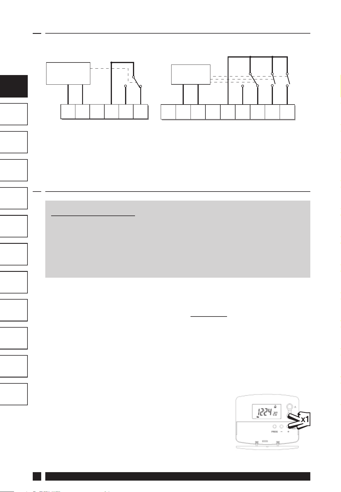
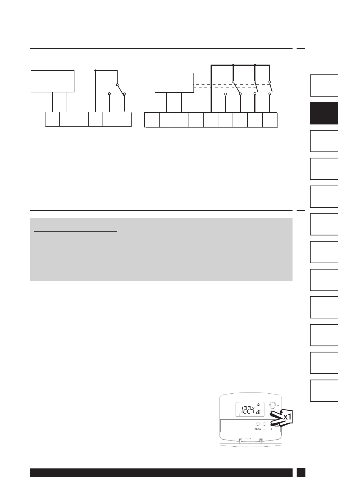
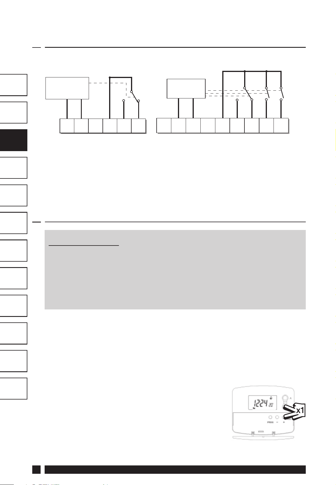
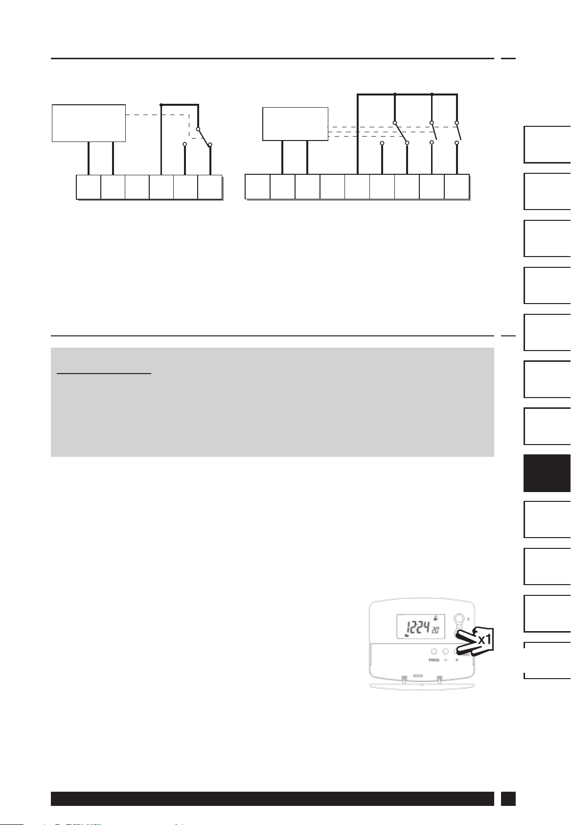
2.2 RX Receiver Wiring (RF models only)
GB
GB
FR
ES
NL
GR
RX1
ELECTRONICS
COM
3
ZONE
1 ON
4
ZONE
1 OFF
A
L
N
1) For mains voltage operated systems link terminal 2 to mains live supply.
2) Power supply to unit must not be switched by timeswitch.
12
RX2 & RX3
ELECTRONICS
C1
B
L
N
345
2
COM
ZONE
1 ON
ZONE
1 OFF
ZONE
2 ON
3.0 Commissioning (RF models only)
IMPORTANT
TERMINAL 6
RX3 ONLY
6
ZONE
3 ON
PL
CZ
TR
HR
RO
HU
On initial installation, or if the batteries have been removed
from the unit for more than 1 minute before beginning
programming or commissioning the TP4000 unit; it is essential
that the RESET button be pressed to ensure the factory preset
programmes are set and the system is fully operational.
If the thermostat and the receiver have been supplied together
in a combined pack, the units have been paired in the factory
and no commissioning is required (RX1 only).
To make the RX receiver learn the thermostat’s signal, follow steps 1-5
below.
Step 1
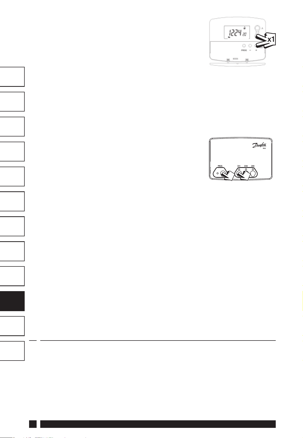
TP4000-RF - Reset the unit by pressing the recessed reset button.
LT
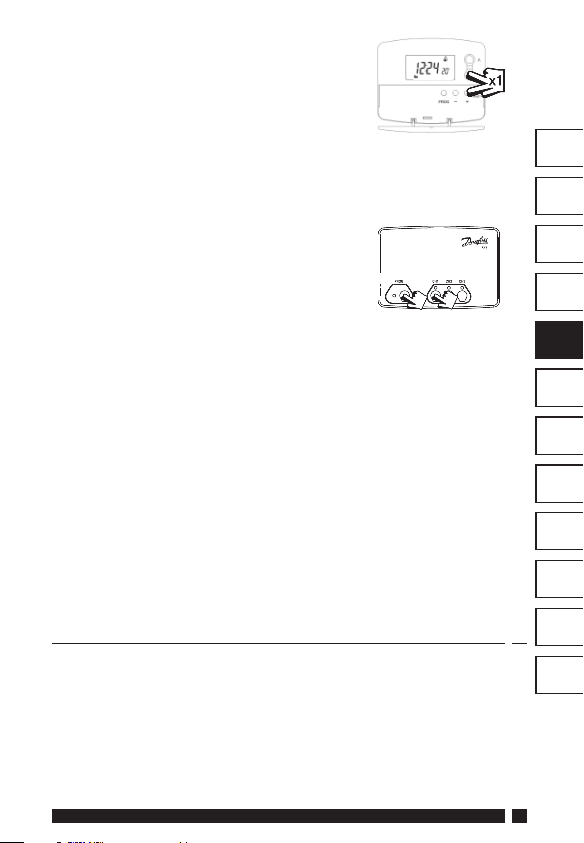
Step 2
Press and hold V and + buttons for 3 seconds
(TP4000 RF now transmits unique signal
continuously for 3 minutes).
6
TP4000
Page 7
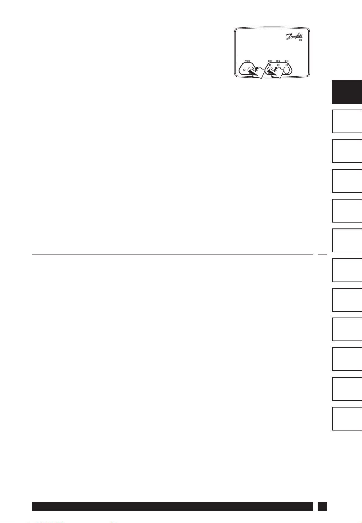
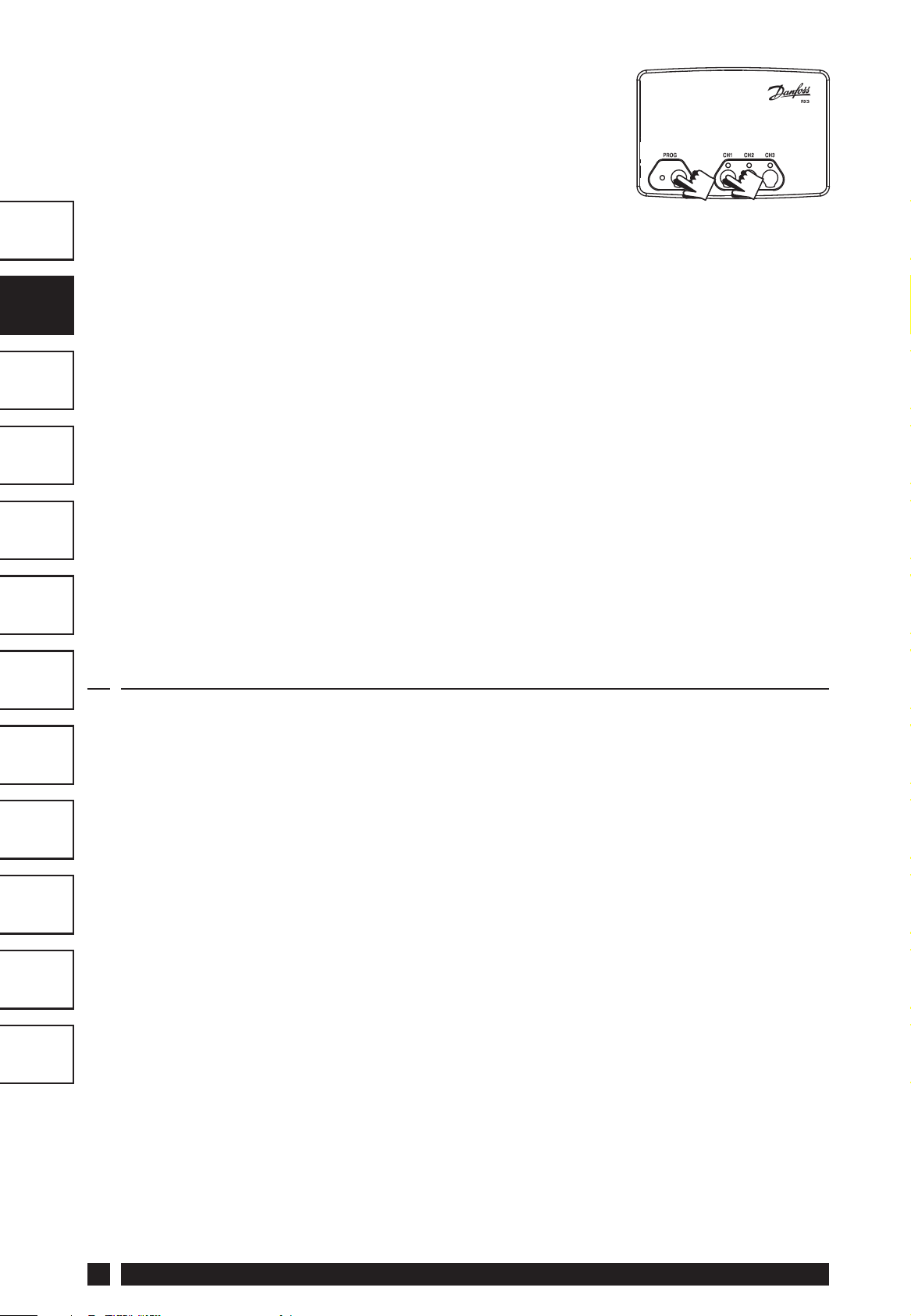
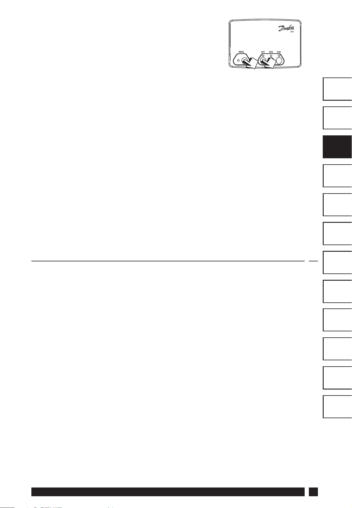
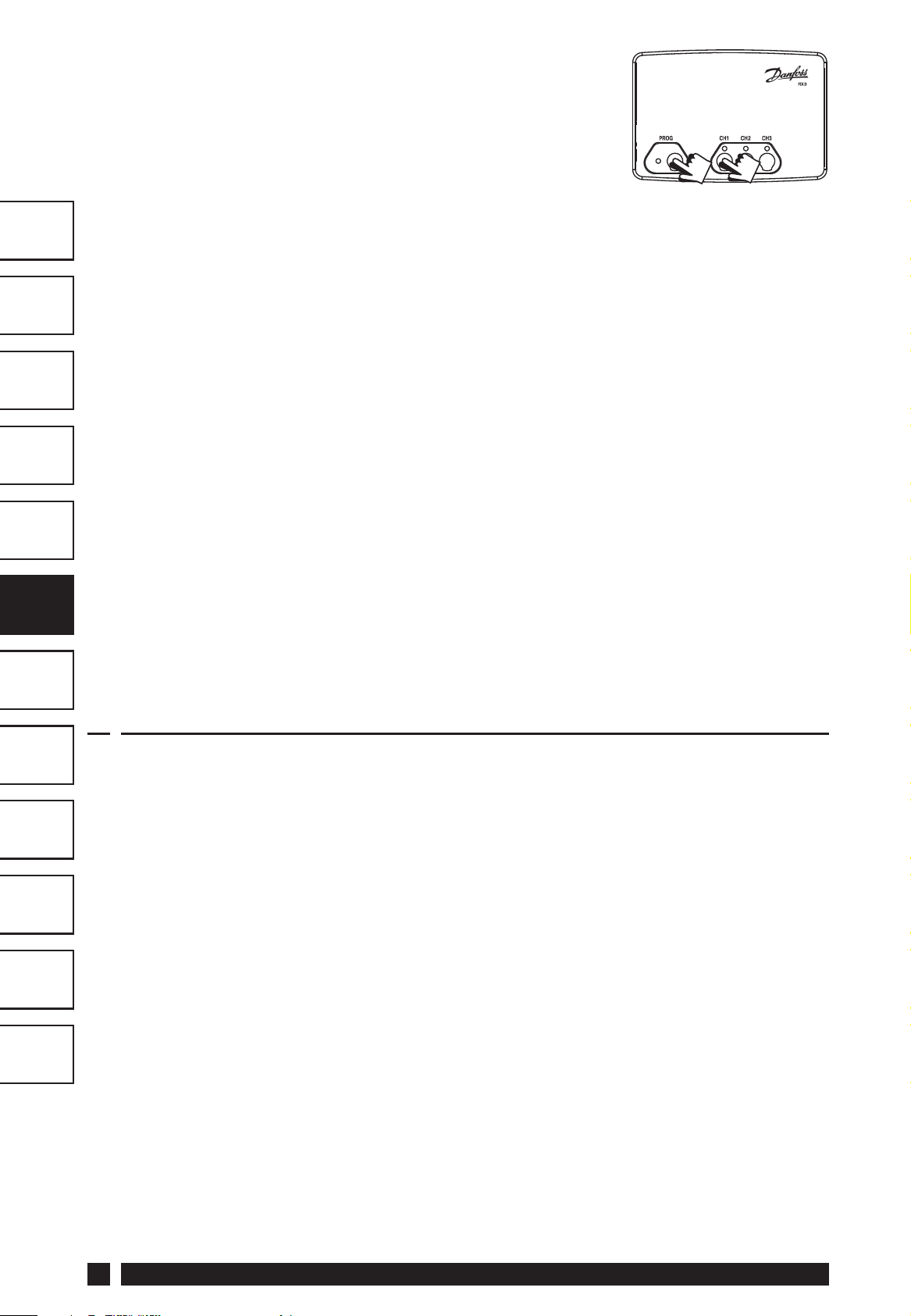
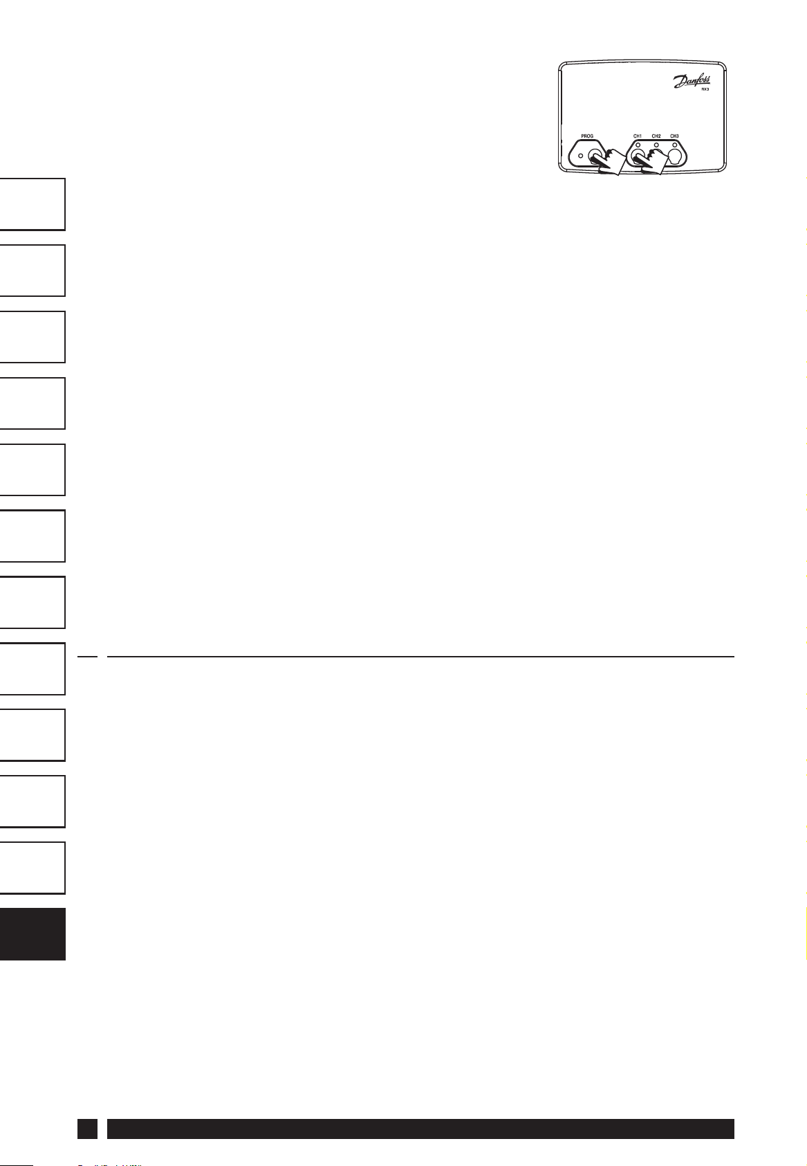
Step 3
RX1 - Press and hold buttons PROG and CH1
for 3 seconds until green light fl ashes once.
Step 4
RX2 (if applicable)
Stat 1 - perform steps 1-3 and 5.
Stat 2 - perform steps 1-2 and then press PROG and CH2 on RX2.
GB
GB
RX3 (if applicable)
Stat 1 - perform steps 1-3 and 5.
Stat 2 - perform steps 1-2 and then press PROG and CH2 on RX3
then step 5.
Stat 3 - perform steps 1-2 and then press PROG and CH3 on RX3.
Step 5
TP4000-RF - Press V or Λ to select temperature - the unit will revert
back to operating mode.
4.0 TP4000/TP4000 RF Programming
For details of this function, please refer to the user instructions.
FR
ES
NL
GR
PL
CZ
TR
HR
RO
HU
LT
Danfoss Heating
7
Page 8
TP4000 Range
Thermostat d’ambiance électronique programmable
GB
FR
FR
ES
NL
GR
PL
Instructions d’installation
CZ
TR
HR
RO
HU
LT
Index
1.0 Spécifi cations ........................................................................................9
2.0 Installation ........................................................................................... 10
2.1 Câblage ............................................................................................ 10
2.2 Câblage du récepteur RX (modèles RF uniquement).....11
3.0 Mise en service (modèles RF uniquement) .................................. 11
4.0 Programmation TP4000/TP4000-RF ........................................ 12
8
TP4000
Page 9
Remarque:
Ce produit doit être installé exclusivement par un électricien
qualifi é ou un installateur de chauff age compétent et doit
être conforme à la version en vigueur des réglementations de
câblage IEEE.
1.0 Spécifi cations
Caractéristiques TP4000 TP4000 RF
GB
FR
FR
Alimentation
Réserve mémoire 1 minute, pour changer les piles
Type de contact
Caractéristique de
contact
Fréquence de l’émetteur
(modèles RF)
Portée de l’émetteur
(modèles RF)
Plage de températures Off , 5-30°C
Dimensions, mm 110 larg, 88 haut, 28 épaiss
Normes de fabrication EN60730-2-9 EN300220 for RF
Tension de choc
nominale
2 piles alcalines x
AA/MN1500
1 x SPDT, Type 1B S/O
3(1)A, 10-230Vac S/O
S/O 433.92MHz
S/O 30m max
2.5kV
2 piles alcalines x
AA/MN1500
ES
NL
GR
PL
CZ
TR
HR
Essai à la bille 75°C
Niveau de recyclage Degré 2
Précision de la
±1°C
température
Précision de l’horloge ±1 min. par mois
Note importante concernant les systèmes RF : Veiller à ce qu’aucun
gros objet métallique (caisson de chaudière ou autre gros appareil
domestique) ne fasse obstacle aux communications entre le thermostat
et le récepteur.
Danfoss Heating
RO
HU
LT
9
Page 10
GB
FR
FR
ES
2.0 Installation
• Retirez tout d’abord la plaque murale de l’arrière de l’appareil.
• Par rapport au coin gauche supérieur de la plaque murale, vous
devez disposer d’espacements d’au moins 150 mm à droite, 15
mm à gauche, 30 mm au-dessus et 100 mm en-dessous afi n de
pouvoir monter le module enfi chable.
NL
GR
PL
CZ
TR
HR
• Fixez l’appareil à une hauteur d’environ 1,5 m du sol, à l’écart des
courants d’air ou des sources de chaleur telles que radiateurs,
feux ouverts ou lumière directe du soleil.
2.1 Câblage
RO
HU
LT
10
N/C
1
OFF
Certains thermostats existants compteront un câble Neutre et/ou Terre
connecté. Ces derniers ne sont pas nécessaires au modèle TP4000 et NE
doivent PAS être connectés à l’une des bornes du TP4000. Ils doivent
!
en revanche être isolés et enroulés dans le renfoncement à l’arrière du
TP4000.
N/O
23
COM ON
TP4000
Page 11
2.2 Câblage du récepteur RX
(modèles RF uniquement)
RX1
Electronique
L
N
1) Pour les systèmes à alimentation secteur, relier la borne 2 à la tension.
2) L’alimentation électrique du thermostat ne doit pas être activée par un
temporisateur.
12
COM
3
Zone 1
Marche
4
Zone 1
Arrét
RX2 et RX3
Electronique
B
N
C1
L
A
345
2
COM
Zone 1
Marche
Zone 1
Arrêt
Zone 2
Marche
6
Zone 3
Marche
Borne 6 RX3
uniquement
3.0 Mise en service (modèles RF uniquement)
GB
FR
FR
ES
NL
GR
IMPORTANT
A la première installlation , ou si les piles ont été retirées plus de
1 minutes du thermostat avant la programmation du TP 4000 ,
il est essentiel d’appuyer sur la touche RESET afi n de remettre
les réglages d’usine et assurer un bon fonctionnement.
Si le thermostat et le récepteur ont été livrés en un seul ensemble,
les unités ont été couplées en usine et aucune mise en service
n’est nécessaire (RX1 uniquement).
Pour coupler manuellement le récepteur au thermostat émetteur , suivre
les cinq étapes suivantes.
Etape 1 TP4000-RF
Remettre le thermostat à zéro en appuyant sur le bouton de remise
à zéro encastré.
PL
CZ
TR
HR
RO
HU
LT
Etape 2 Appuyer et maintenir enfoncées les
touches V et + pendant 3 secondes (le TP4000
RF Si émet alors un signal unique en continu
pendant 3 minutes)
Danfoss Heating
11
Page 12
Etape 3 RX1
Appuyer et maintenir enfoncées les touches
PROG et CH1 pendant 3 secondes jusqu’à ce
que le témoin lumineux vert clignote une fois.
Etape 4 RX2 (le cas échéant)
GB
FR
FR
ES
NL
GR
PL
CZ
Stat 1 - eff ectuer les opérations 1-3 et 5.
Stat 2 - eff ectuer les opérations 1-2 puis appuyer sur PROG et CH2
sur RX2.
RX3 (le cas échéant)
Stat 1 - eff ectuer les opérations 1-3 et 5.
Stat 2 - eff ectuer les opérations 1-2 puis appuyer sur PROG et CH2 sur
RX3 puis eff ectuer l’opération 5.
Stat 3 - eff ectuer les opérations 1-2 puis appuyer sur PROG et CH3 sur
RX3.
Etape 5 TP4000-RF
Appuyer sur V ou Λ pour choisir la température – le thermostat
revient à son mode de fonctionnement.
4.0 Programmation TP4000/TP4000-RF
TR
HR
RO
HU
LT
Voir la notice utilisateur pour plus de détail.
12
TP4000
Page 13
TP4000 Range
Cronotermostato
Instrucciones de instalació
GB
FR
ES
ES
NL
GR
PL
Indice
1.0 Especifi caciones ................................................................................ 14
2.0 Instalación ............................................................................................ 15
2.1 Cableado ........................................................................................ 15
2.2 Cableado del receptor RX (únicamente en modelos RF) ... 16
3.0 Puesta en marcha (únicamente modelos RF)............................... 16
4.0 Programación TP4000/TP4000RF ............................................. 17
CZ
TR
HR
RO
HU
LT
Danfoss Heating
13
Page 14
GB
FR
Observe que:
Este producto deberá ser instalado solamente por un electricista
cualifi cado o por un instalador de calefacción competente
y deberá instalarse de acuerdo con la edición vigente de las
normas de cableado de la IEEE.
1.0 Especifi caciones
Especifi caciones TP4000 TP4000 RF
ES
ES
NL
GR
PL
CZ
TR
Alimentación
Respaldo de batería 1 minuto, para cambio de batería
Tipo de contacto
Carga de los contactos 3(1)A, 10-230Vac N/D
Frecuencia de
transmisión
(en los modelos RF)
Alcance de transmisión
(en los modelos RF)
Rango de temperatura OFF, 5-30°C
Dimensiones generales
(mm)
Norma de fabricación EN60730-2-9 EN300220
2 pilas AA / MIN 1500
/ LR 6
1 x SPDT N/D
N/D 433.92MHz
N/D Máximo 30 m
110 An, 88 Al, 29 Pr
2 pilas AA / MIN 1500
/ LR 6
HR
RO
HU
LT
Tensión nominal del
impulso
Ensayo de presión con
bola
Control antipolución Grado 2
Precisión de
temperatura
Exactitud en la hora ±1 min. p/mes
Nota importante acerca de los productos RF: Asegúrese de que no
haya grandes objetos metálicos tales como equipos calentadores de
agua u otros grandes artefactos que obstaculicen la línea de visión entre
el transmisor y el receptor pues impedirían la comunicación entre el
termostato y el receptor.
14
2.5kV
75°C
±1°C
TP4000
Page 15
2.0 Instalación
· En primer lugar, quitar la placa mural de la parte trasera de la
unidad.
· Desde la esquina superior izquierda de la placa mural, debe haber
GB
FR
un espacio libre de al menos 150mm a la derecha, de 15mm a la
izquierda, de 30mm arriba y de 100mm abajo con el fi n de montar
el módulo enchufable.
· Montarlo a una altura de aproximadamente 1,5 m desde el
suelo, lejos de corrientes de aire o de fuentes de calor tales como
radiadores, fuegos descubiertos o rayos solares directos.
2.1 Cableado
ES
ES
NL
GR
PL
CZ
TR
HR
N/C
1
OFF
Algunos termostatos existentes tendrán un cable Neutro y/o un cable
de conexión a Tierra. Estos cables no son necesarios para el TP4000
y NO deben conectarse a ningún terminal del TP4000. En lugar de
!
eso los cables deberán aislarse eléctricamente de modo seguro y
enrollarse dentro de un hueco en la parte trasera del TP4000.
Danfoss Heating
N/O
23
COM ON
RO
HU
LT
15
Page 16
2.2 Cableado del receptor RX
(únicamente en modelos RF)
GB
FR
ES
ES
NL
GR
PL
RX1
Electrónica
L
N
1) Para sistemas que funcionen con tensión de red, conecte la alimentación al terminal 2.
2) La alimentación eléctrica a la unidad no debe interrumpirse con un temporizador.
12
COMÚN
3
4
ZONA 1 APAGADA
ZONA 1 ENCENDIDA
RX2 y RX3
Electrónica
B
N
C1
L
A
2
COMÚN
345
ZONA 1 APAGADA
ZONA 1 ENCENDIDA
ZONA 2 ENCENDIDA
TERMINAL 6
ÚNICAMENTE
EN RX3
6
ZONA 3 ENCENDIDA
3.0 Puesta en marcha (únicamente modelos RF)
CZ
TR
HR
RO
HU
LT
IMPORTANTE
En la primera instalación , ó si se han quitado las pilas de la
unidad durante más de 1 minuto antes de empezar a programar
la unidad TP4000; es fundamental presionar el boton RESET
para asegurar que estan fi jados los programas establecidos de
fábrica y el sistema funciona completamente.
Si el cronotermostato y el receptor han sido suministrados como
un conjunto (Kit), ambos han sido emparejados en la fábrica y la
puesta en marcha no es necesaria (sólo RX1).
Para sintonizar el receptor RX en la frecuencia de la señal del
cronotermostato, siga los pasos 1 al 5 que se indican a continuación.
Paso 1 TP4000-RF - Reinicie la unidad
pulsando el pulsador de reinicio embutido.
Paso 2 Pulse y mantenga pulsados V y +
durante 3 segundos (el TP4000 RF transmite
ahora una señal única y continua durante 3
minutos).
16
TP4000
Page 17
Paso 3 RX1 - Pulse y mantenga pulsados
PROG y CH1 durante 3 segundos hasta que la
luz verde emita un destello.
Paso 4 RX2 (si es aplicable)
Receptor 1 - ejecute los pasos 1 a 3 y 5.
Receptor 2 - los pasos 1 y 2 y luego pulse PROG y CH2 en el RX2.
GB
RX3 (si es aplicable)
Receptor 1 - ejecute los pasos 1 a 3 y 5.
Receptor 2 - ejecute los pasos 1 y 2, seguidamente pulse PROG y
CH2 en el RX3 y luego ejecute el paso 5.
Receptor 3 - ejecute los pasos 1 y 2 y luego pulse PROG y CH3 en
el RX3.
Paso 5 TP4000-RF
Pulse V o Λ para seleccionar la temperatura; la unidad volverá al modo
operativo.
4.0 Programación TP4000/TP4000RF
Para ver los detalles de esta función, por favor, lease las instrucciones
de usuario.
FR
ES
ES
NL
GR
PL
CZ
TR
Danfoss Heating
HR
RO
HU
LT
17
Page 18
TP4000 Range
Programmeerbare kamer thermostaat
GB
FR
ES
NL
NL
GR
PL
Installatie handleiding
CZ
TR
HR
RO
HU
LT
Index
1.0 Technische specifi caties ................................................................ 19
2.0 Montage ................................................................................................ 20
2.1 Aansluiting ....................................................................................20
2.2 Aansluiting van de RX-ontvanger (alleen bij RF-modellen) .... 21
3.0 Inbedrijfstelling (alleen RF-modellen) ................................... 21
4.0 TP4000/TP4000RF Instellen ........................................................ 22
18
TP4000
Page 19
N.B.:
Dit product dient alleen te worden geïnstalleerd door een erkend
elektrotechnicus of een vakkundige verwarmingsinstallateur
conform de thans geldende IEEE-voorschriften voor bedrading.
1.0 Technische specifi caties
Omschrijving TP4000 TP4000 RF
Voeding
2 x AA / MN1500
Alkaline batterijen
Programma backup 1 minuut, voor wisselen batterijen
SPDT Type 1B
Relaiscontact
potentiaalvrij
Maximum
10-230Vac, 3(1)A n.v.t.
contactbelasting
Bedrijfsfrequentie
n.v.t. 433.92MHz
(RF-modellen)
Zendbereik
n.v.t. 30m max.
(RF-modellen)
2 x AA / MN1500
Alkaline batterijen
n.v.t.
GB
FR
ES
NL
NL
GR
PL
CZ
Temperatuurbereik Off , 5-30°C
Afmetingen (bxhxd) 110 x 88 x 29mm
Constructienorm EN60730-2-9 EN300220
Nominale piekspanning 2,5kV
Kogeldruktest 75°C
Stralingsniveau Graad 2
Nauwkeurigheid ±1°C
Tijdnauwkeurigheid ±1 min. per maand
Belangrijk voor RF-modellen: Let erop dat zich geen grote metalen
voorwerpen zoals ketels of andere grote apparaten in de zichtlijn tussen
thermostaat en ontvanger bevinden, aangezien de communicatie
tussen thermostaat en ontvanger hierdoor wordt verhinderd.
TR
HR
RO
HU
LT
Danfoss Heating
19
Page 20
GB
FR
ES
2.0 Montage
• Verwijder eerst de wandplaat van de achterkant van de
thermostaat.
• Monteer de wandplaat op een hoogte van ca. 1,5 m vanaf de
vloer, niet op de tocht en uit de buurt van warmtebronnen zoals
radiatoren, open haard of direct zonlicht.
NL
NL
GR
PL
CZ
TR
HR
• Rondom de wandplaat dient een vrije ruimte van minimaal 140
mm te worden aangehouden.
2.1 Aansluiting
RO
HU
LT
20
N/C
1
OFF
Op sommige bestaande thermostaten kan een Nul- en/of Aardedraad
zijn aangesloten. Deze zijn niet nodig op de TP4000 en mogen NIET op
de klemmen van de TP4000 worden aangesloten. Zij moeten worden
!
geïsoleerd en worden opgerold in de uitsparing van de TP4000.
N/O
23
COM ON
TP4000
Page 21

2.2 Aansluiting van de RX-ontvanger
(alleen bij RF-modellen)
RX1
Electronica
L
N
1) Bij systemen met netvoeding dient klem 2 te worden aangesloten op de fase van
de netvoeding.
2) De voeding van de ontvanger mag niet via een schakelklok lopen.
12
COM
3
ZONE 1 AAN
4
ZONE 1 UIT
RX2 en RX3
Electronica
B
N
C1
L
A
345
2
COM
ZONE 1 AAN
ZONE 1 UIT
6
ZONE 2 AAN
Aansluitpunt 6
(alleen RX3)
ZONE 3 AAN
3.0 Inbedrijfstelling (alleen RF-modellen)
BELANGRIJK - Bij eerste inbedrijfstelling, of wanneer
de batterijen langer dan 1 minuut uit de thermostaat zijn
GB
FR
ES
NL
NL
GR
PL
verwijderd, is het noodzakelijk dat de thermostaat gereset
wordt.
Dit om er zeker van te zijn dat de fabieksinstellingen van de
thermostaat zijn teruggezet, en de thermostaat klaar is voor
gebruik.
Als de thermostaat en de ontvanger samen als een gecombineerd
pakket zijn geleverd, zijn zij in de fabriek reeds op elkaar
afgestemd en is inbedrijfstelling niet nodig (alleen RX1).
Afstemmen van de RX-ontvanger op de frequentie van het
thermostaatsignaal: volg onderstaande stappen 1-5.
Stap 1 TP4000-RF
Reset de thermostaat door de resetknop in
de uitsparing in te drukken.
CZ
TR
HR
RO
HU
LT
Stap 2 Houd de knoppen V en + gedurende
3 seconden ingedrukt (de TP4000-RF zendt
nu gedurende 3 minuten continu een uniek
signaal uit).
Danfoss Heating
21
Page 22

Stap 3 RX1
Houd de knoppen PROG en CH1 gedurende
3 seconden ingedrukt tot het groene lampje
1 maal oplicht.
Stap 4 RX2 (indien van toepassing)
GB
FR
ES
NL
NL
GR
PL
CZ
Thermostaat 1 - voer stappen 1-3 en 5 uit.
Thermostaat 2 - voer stappen 1-2 uit en druk vervolgens op PROG
en CH2 op de RX2.
RX3 (indien van toepassing)
Thermostaat 1 - voer stappen 1-3 en 5 uit.
Thermostaat 2 - voer stappen 1-2 uit en druk vervolgens op PROG
en CH2 op de RX3. Voer daarna stap 5 uit.
Thermostaat 3 - stappen 1-2 uit en druk vervolgens op PROG en
CH3 op de RX3.
Stap 5 TP4000-RF
Druk op V of Λ om de temperatuur te selecteren - de thermostaat
schakelt weer in de bedrijfsstand.
4.0 TP4000/TP4000RF Instellen
TR
HR
RO
HU
LT
Raadpleeg de handleiding voor meer uitleg over deze functie.
22
TP4000
Page 23

TP4000 Range
Ηλεκτρονικός προγραμματιζόμενος
θερμοστάτης χώρου
Оδηγίες εγκατάστασης
GB
FR
ES
NL
GR
GR
PL
CZ
Περιεχόμενα
1.0 Προδιαγραφή ..................................................................................... 24
2.0 Εγκατάσταση ......................................................................................25
2.1 Ηλεκτρική σύνδεση .................................................................... 25
2.2 Σύνδεση RX δέκτη (μόνο για τους τύπους RF) .................. 26
3.0 Οδηγίες ρύθμισης (μόνο για τους τύπους RF) .....................26
4.0 Προγραμματισμός TP4000/TP4000 RF .................................. 27
TR
HR
RO
HU
LT
Danfoss Heating
23
Page 24

GB
FR
ES
Παρακαλούμε σημειώστε:
Αυτό το προϊόν θα πρέπει να εγκαθίσταται από ειδικευμένο
ηλεκτρολόγο ή αρμόδιο θερμικό εγκαταστάτη και θα πρέπει
να είναι σύμφωνο με την ισχύουσα έκδοση των κανονισμών
ηλεκτρικών εγκαταστάσεων του ΙΕΕΕ.
1.0 Προδιαγραφή
Χαρακτηριστικά TP4000 TP4000 RF
Mπαταρίες λειτουργίας 2 x AA / MN 1500
αλκαλικές
2 x AA / MN 1500
αλκαλικές
NL
GR
GR
PL
CZ
TR
HR
RO
Διάρκεια μνήμης 1 λεπτό, για αλλαγή μπαταρίας
Τύπος επαφής ρελέ
Τάση ρελέ 3(1)A, 10-230 Vac
Συχνότητα μετάδοσης
(μόνο για τους τύπους RF)
Εμβέλεια μετάδοσης
Περιοχή θερμοκρασιών Off , 5-30°C
Διαστάσεις
(μήκος x ύψος x βάθος)
Προδιαγραφές
σχεδιασμού
Ονομαστική τάσης
ώθησης
Δοκιμή σφαιρικής πίεσης 75°C
Κατάσταση ελέγχου
ρύπανσης
SPDT τύπος 1Β N/A
N/A
N/A
N/A
110 mm x 88 mm x 29 mm
EN60730-2-9 EN300220
2.5kV
Degree 2
433.92MHz
30m max
HU
LT
Ακρίβεια θερμοκρασίας ±1°C
Ακρίβεια χρόνου ±1 min. tο μήνα
Σημαντική σημείωση για τους τύπους RF: Εξασφαλίστε ότι δεν
υπάρχει κανένα μεγάλο μεταλλικό αντικείμενο που παρεμβάλλεται,
όπως οι περιπτώσεις λεβήτων ή άλλες μεγάλες συσκευές, μεταξύ της
συσκευής πομπού και του δέκτη σήματος, έτσι ώστε να αποτρέπεται
ή πιθανόν διαταραχή επικοινωνίας μεταξύ θερμοστάτη και δέκτη.
24
TP4000
Page 25

2.0 Εγκατάσταση
· Πρώτα, αφαιρέστε το πάνελ από το πίσω μέρος της μονάδας.
· Από την πάνω αριστερή γωνία του πάνελ πρέπει να υπάρχουν
GB
FR
ελεύθερες αποστάσεις τουλάχιστον 150 mm προς τα δεξιά, 15
mm προς τα αριστερά, 30 mm προς τα επάνω και 100 mm προς
τα κάτω για την εγκατάσταση του θηλυκωτού δομοστοιχείου.
· Στερεώστε σε ύψος περίπου 1,5 m από το δάπεδο μακριά από
ρεύματα ή πηγές θερμότητας όπως σώματα καλοριφέρ, γυμνή
φλόγα ή άμεσο ηλιακό φως.
2.1 Ηλεκτρική σύνδεση
ES
NL
GR
GR
PL
CZ
TR
N/C
1
OFF
Μερικοί υπάρχοντες θερμοστάτες έχουν συνδεδεμένο τον
ουδέτερο αγωγό και/ή τον αγωγό γείωσης. Αυτοί οι αγωγοί δεν
απαιτούνται από το TP4000 και ΔΕΝ πρέπει να συνδέονται σε
!
ακροδέκτες TP4000, αλλά θα πρέπει να καθίστανται ηλεκτρικά
ασφαλείς και να συστρέφονται στην εσοχή στο πίσω μέρος του
TP4000.
Danfoss Heating
N/O
23
COM ON
HR
RO
HU
LT
25
Page 26

2.2 Σύνδεση RX δέκτη (μόνο για τους τύπους RF)
GB
FR
ES
NL
GR
GR
RX1
ELECTRONICS
L
N
1) Στο τερματικό συνδεσμολογίας χρησιμοποιείστε το σημείο 2 για την σύνδεση
φάσης τροφοδοσίας.
2) Η παροχή ηλεκτρικού ρεύματος στη μονάδα δεν πρέπει να διακόπτεται από το
χρονοδιακόπτη.
12
COM
3
ZONE
1 ON
4
ZONE
1 OFF
A
RX2 & RX3
ELECTRONICS
C1
B
L
N
345
2
COM
ZONE
1 ON
ZONE
1 OFF
ZONE
2 ON
TERMINAL 6
RX3 ONLY
6
ZONE
3 ON
3.0 Οδηγίες ρύθμισης (μόνο για τους τύπους RF)
PL
CZ
TR
HR
RO
HU
LT
ΣΗΜΑΝΤΙΚΟ
Στην αρχική εγκατάσταση, ή εάν οι μπαταρίες έχουν αφαιρεθεί
από τη μονάδα για περισσότερο από 1 λεπτό πριν από το
προγραμματισμό τη ρύθμιση της μονάδας TP4000, είναι
απαραίτητο ότι το κουμπί επαναφοράς RESET πρέπει να
πατηθεί για τη εξασφάλιση επαναφοράς του εργοστασιακού
προγράμματος και τη πλήρη ετοιμότητα λειτουργίας.
Εάν η θερμοστάτης και ο δέκτης έχουν παραδοθεί μαζί μέσα σε
συνδυασμένη συσκευασία, οι μονάδες έχουν συντονιστεί και
ρυθμιστεί από το εργοστάσιο και δεν απαιτείται καμία ρύθμιση
(τύπος RX1 μόνο)
Για τη ρύθμιση συντονισμού σήματος του δέκτη RX με τον θερμοστάτη
ακολουθείστε τα παρακάτω βήματα 1-5
26
TP4000
Page 27
Βήμα 1
ΤΡ4000-RF - Επαναρυθμίστε τη μονάδα με τη
συμπίεση του κουμπί επαναφοράς reset.
Βήμα 2
Πιέστε κρατήστε τα V και + κουμπιά για 3
δευτερόλεπτα (Ο TP4000 RF διαβιβάζει τώρα ένα μοναδικό σήμα
συνεχώς για 3 λεπτά).
Βήμα 3
RX1 - Πιέστε και κατήστε πατημένα τα κουμπιά
PROG και CH1 για 3 δευτερόλεπτα μέχρι να
ανάψει μια φορά η πράσινη λυχνία
Βήμα 4
RX2 (εφόσον υπάρχει)
Στάδιο 1 - εκτελέστε τα βήματα 1-3 και 5.
GB
FR
ES
NL
GR
GR
Στάδιο 2 - εκτελέστε τα βήματα 1-2 και μετά πατήστε PROG και CH2
για τον RX2.
RX3 (εφόσον υπάρχει)
Στάδιο 1 - εκτελέστε τα βήματα 1-3 και 5.
Στάδιο 2 - εκτελέστε τα βήματα 1-2 και μετά πατήστε PROG και CH2
για τον RX3 και μετά πατήστε
Στάδιο 2 - εκτελέστε τα βήματα 1-2 και μετά πατήστε PROG και CH3
για τον RX3.
Βήμα 5
TP4000-RF - Πατήστε V ή Λ για να επιλέξτε την θερμοκρασία - η
μονάδα θα επανέλθει πίσω στη κανονική θέση λειτουργίας.
Βήμα 5
4.0 Προγραμματισμός TP4000/TP4000 RF
PL
CZ
TR
HR
RO
HU
Για τις λεπτομέρειες αυτής της λειτουργίας, παρακαλώ δείτε στις
οδηγίες χρήσης.
Danfoss Heating
LT
27
Page 28

TP4000 Range
Elektroniczny programowalny termostat
pokojowy
GB
FR
ES
NL
GR
GR
PL
PL
CZ
Instrukcja montażu
TR
HR
RO
HU
LT
Index
1.0 Specyfi kacja ........................................................................................ 29
2.0 Instalacja ............................................................................................... 30
2.1 Podłączanie przewodów .......................................................... 30
2.2 Połączenia elektryczne odbiornika RX (tylko modele RF) ... 31
3.0 Dostrajanie (tylko modele RF) ....................................................31
4.0 TP4000/TP4000 RF Programowanie ........................................ 32
28
TP4000
Page 29

Prosimy pamiętać:
Produkt ten powinien być instalowany wyłącznie przez
wykwalifi kowanego elektryka lub instalatora ogrzewania.
Montaż należy przeprowadzać zgodnie z aktualnymi przepisami
dotyczącymi przewodów elektrycznych IEEE.
1.0 Specyfi kacja
Specyfi kacja TP4000 TP4000 RF
GB
FR
Zasilanie
Podtrzymanie pamięci 1 minuta, dla wymiany baterii
Typy wbudowanych
przekaźników
Obciążalność styków 3(1)A, 10-230Vac
Częstotliwość transmisji
(modele częstotliwości
radiowej - RF)
Odległość komunikacji
Zakres temperatury Off , 5-30°C
Wymiary (mm) 110 dł., 88wys., 29 szer.
Zgodno
Znamionowe napiecie
impulsu
ść z normą EN60730-2-9 EN300220
2 x AA / MN 1500 / LR
6 Baterie
1 x SPDT, Type 1B N/A
N/A
N/A
2.5kV
2 x AA / MN 1500 / LR
6 Baterie
N/A
433,92MHz
30m max
ES
NL
GR
PL
PL
CZ
TR
HR
Test twardości 75°C
Dokładność regulacji ±1°C
Dokładność czasu ±1 min. miesięcznie
Ważna uwaga dot. wyrobów częstotliwości radiowej (RF):
dopilnować, aby na linii wzroku między nadajnikiem, a odbiornikiem nie
znajdowały się duże przedmioty metalowe, takie jak obudowy bojlerów
lub inne duże urządzenia, gdyż mogą one uniemożliwić łączność między
termostatem a odbiornikiem.
Danfoss Heating
RO
HU
LT
29
Page 30

GB
FR
ES
2.0 Instalacja
· Najpierw usuń pokrywę z tylnej części urządzenia.
· Aby zamontować przewód, w lewym górnym rogu pokrywy musi
znajdować się wolny obszar o wymiarach przynajmniej 150 mm z
prawej strony, 15 mm z lewej, 30 mm powyżej i 100 mm poniżej
pokrywy.
NL
GR
PL
PL
CZ
TR
HR
· Zamontuj urządzenie w odległości około 1,5 m od podłogi, z dala
od przeciągów oraz źródeł ciepła, takich jak grzejniki, otwarty
ogień czy bezpośrednie światło słoneczne.
2.1 Podłączanie przewodów
RO
HU
LT
30
N/C
1
OFF
Niektóre termostaty mają podłączony przewód zerowy oraz/lub
przewód uziomowy. Przewody te nie są wymagane dla modelu TP4000
i NIE NALEŻY ich podłączać do żadnych złączy TP4000. Należy je
!
natomiast zaizolować, zwinąć i umieścić we wnęce z tyłu urządzenia.
N/O
23
COM ON
TP4000
Page 31
2.2 Połączenia elektryczne odbiornika RX
(tylko modele RF)
RX1
ELECTRONICS
L
N
1) W systemach na zasilanie sieciowe końcówkę 2 należy podłączyć do fazy.
2) Zasilanie urządzenia nie może w żadnym przypadku być włączane przez
przełącznik czasowy.
12
COM
3
ZONE
1 ON
4
ZONE
1 OFF
RX2 oraz RX3
ELECTRONICS
B
N
C1
L
A
345
2
COM
ZONE
1 ON
ZONE
1 OFF
ZONE
2 ON
3.0 Dostrajanie (tylko modele RF)
WAŻNE
TERMINAL 6
RX3 ONLY
6
ZONE
3 ON
GB
FR
ES
NL
GR
PL
PL
Przy pierwszym uruchomieniu, lub gdy baterie zostały wyjęte
z jednostki na ponad 1 minutę przed programowaniem
jednostki TP4000, ważne jest żeby przycisk RESET był wciśnięty
dla zapewnienia, że aktywne są ustawienia fabryczne a system
jest w pełni operacyjny.
Jeżeli termostat i odbiornik zostały dostarczone w jednym
zestawie, wówczas urządzenia te zostały dostrojone fabrycznie i
dostrojenie nie jest wymagane (tylko RX1).
Celem dostrojenia odbiornika RX do częstotliwości sygnału termostatu
należy wykonać wskazane niżej czynności 1-5.
Czynność 1 TP4000-RF
Zresetować urządzenie naciskając znajdujący
się we wgłębieniu przycisk reset.
CZ
TR
HR
RO
HU
LT
Czynność 2 Nacisnąć i przytrzymać przez
3 sekundy przyciski V oraz + (teraz TP4000RF zaczyna wysyłać w sposób ciągły przez 3
minuty unikatowy sygnał).
Danfoss Heating
31
Page 32
Czynność 3 RX1
Nacisnąć i przytrzymać przez 3 sekundy
przyciski PROG oraz CH1, aż do czasu
jednorazowego zamigotania zielonego
światełka.
GB
FR
ES
NL
GR
PL
PL
CZ
Czynność 4 RX2 (ewentualnie)
Stat 1 - wykonać czynności 1-3 oraz 5.
Stat 2 - wykonać czynności 1-2 a następnie nacisnąć PROG oraz
CH2 na RX2.
RX3 (ewentualnie)
Stat 1 - wykonać czynności 1-3 oraz 5.
Stat 2 - wykonać czynności 1-2 a następnie nacisnąć PROG oraz CH
2 na RX3, a następnie czynność 5.
Stat 3 - wykonać czynności 1-2 a następnie nacisnąć PROG oraz CH
3 na RX3.
Czynność 5 TP4000-RF
Nacisnąć V lub Λ celem wyboru temperatury – urządzenie powróci
do trybu operacyjnego.
4.0 TP4000/TP4000 RF Programowanie
TR
HR
RO
HU
LT
Szczegółowe informacje na temat tej funkcji znajdują się w instrukcji
obsługi użytkownika.
32
TP4000
Page 33
TP4000 Range
Elektronický programovatelný prostorový
termostat
Instalační příručka
GB
FR
ES
NL
GR
PL
CZ
CZ
Obsah
1.0 Specifi kace výrobku ........................................................................ 34
2.0 Instalace ................................................................................................ 35
2.1 Elektrické zapojení termostatu .............................................. 35
2.2 Elektrické zapojení přijímače RX
(pouze pro modely RF) ...................................................................... 36
3.0 Uvedení do provozu (pouze pro modely RF) ......................31
4.0 TP4000/TP4000 RF programování ........................................... 37
TR
HR
RO
HU
LT
Danfoss Heating
33
Page 34
GB
FR
Vezměte prosím na vědomí:
Tento výrobek by měl být nainstalován pouze kvalifi kovaným
elektrikářem nebo způsobilým topenářem a instalace by měla být
provedena v souladu s aktuálním vydáním elektroinstalačních
předpisů IEEE.
1.0 Specifi kace výrobku
ES
NL
GR
PL
CZ
CZ
TR
Charakteristika
termostatu
Elektrické napájení 2 alkalické články
Zálohování paměti 1 minuta pro výměnu baterie
Spínání výstupního relé
Spínací parametry
reléového kontaktu
Přenosová frekvence
(vysokofrekvenční modely)
Dosah přenosu nevztahuje se max. 30 m
Teplotní rozsah 5-30°C
Rozměry v mm šířka 110, výška 88, hloubka 28
Konstrukční norma EN60730-2-9 EN300220
TP4000 TP4000 RF
2 alkalické články
AA/MN1500/LR
1 x SPDT, typ 1B
3(1)A, 10-230 V AC nevztahuje se
nevztahuje se 433.92MHz
AA/MN1500/LR
nevztahuje se
HR
RO
HU
LT
Jmenovité impulsní napětí 2.5kV
Zkouška tvrdosti podle
Brinella
Klasifi kace pro regulaci
znečištění
Přesnost teploty ±1°C
Časová přesnost ±1 min. za měsíc
Důležitá poznámka k vysokofrekvenčním výrobkům: Zajistěte, aby
ve vizuální linii mezi vysílačem a přijímačem nebyly žádné velké kovové
předměty, jako např. skříně kotlů či bojlerů nebo jiné velké spotřebiče,
neboť výskyt těchto zařízení by bránil v přenosu dat mezi termostatem
a přijímačem.
34
75°C
stupeň 2
TP4000
Page 35
2.0 Instalace
· Nejprve odstraňte nástěnnou destičku ze zadní části jednotky.
· Od horního levého rohu nástěnné destičky musí být prostor
alespoň 150 mm doprava, 15 mm doleva, 30 mm nahoru a 100
mm dolů, aby bylo možno namontovat spínací modul.
· Namontujte zařízení ve výšce 1,5 m od podlahy, mimo proudění
GB
FR
ES
vzduchu nebo zdroje tepla jako jsou radiátory, otevřený oheň
nebo přímé sluneční světlo.
2.1 Elektrické zapojení termostatu
NL
GR
PL
CZ
CZ
TR
HR
N/C
1
OFF
!
Danfoss Heating
COM ON
Některé stávající termostaty mají nulový a/nebo uzemňovací vodič.
Tyto vodiče nejsou požadovány pro termostat TP4000 a NESMĚJÍ
být připojeny k žádným svorkám zařízení TP4000. Namísto toho je
potřeba tyto vodiče elektricky zajistit a svinout ve výklenku v zadní
části jednotky TP4000.
RO
N/O
HU
23
LT
35
Page 36

2.2 Elektrické zapojení přijímače RX
(pouze pro modely RF)
GB
FR
ES
NL
GR
PL
RX1
ELECTRONICS
COM
3
ZONE
1 ON
4
ZONE
1 OFF
A
L
N
1) Pro systémy pracující na síťové napětí připojte svorku 2 k síťovému napájení.
2) Napájení do jednotky nesmí být spínáno časovým spínačem.
12
RX2 & RX3
ELECTRONICS
C1
B
L
N
345
2
COM
ZONE
1 ON
ZONE
1 OFF
ZONE
2 ON
TERMINAL 6
RX3 ONLY
6
ZONE
3 ON
3.0 Uvedení do provozu (pouze pro modely RF)
DŮLEŽITÉ UPOZORNĚNÍ
Před zahájením programování či kontrolou TP4000, při
CZ
CZ
TR
HR
RO
HU
LT
počáteční instalaci nebo v případě vyjmutí baterií z termostatu
více než na 1 minutu, je nutné resetovat přístroj. Resetování
uskutečníte tlačítkem RESET a slouží k zajištění továrního
nastavení programů a zajištění funkčnosti systému
Jestliže byl termostat a přijímač dodán společně v rámci jednoho
balíčku, byly tyto jednotky spárovány již ve výrobním závodě a
jejich uvádění do provozu není potřeba (pouze pro RX1).
Abyste zajistili, že přijímač RX bude identifi kovat signál termostatu,
proveďte kroky 1-5 uvedené níže.
Krok 1
TP 4000 RF – Proveďte nové nastavení jednotky stisknutím
zapuštěného tlačítka reset.
Krok 2
Stiskněte a držte tlačítka V a + po dobu 3 sekund
(termostat TP 4000 RF bude nyní vysílat unikátní
signál nepřetržitě po dobu 3 minut).
36
TP4000
Page 37

Jestliže byl termostat a přijímač dodán společně
v rámci jednoho balíčku, byly tyto jednotky
spárovány již ve výrobním závodě a jejich
uvádění do provozu není potřeba (pouze pro
RX1).
Abyste zajistili, že přijímač RX bude identifi kovat signál termostatu,
proveďte kroky 1-5 uvedené níže.
Krok 1
TP 4000 RF – Proveďte nové nastavení jednotky stisknutím
zapuštěného tlačítka reset.
Krok 2
Stiskněte a držte tlačítka V a + po dobu 3 sekund (termostat TP 4000 RF
bude nyní vysílat unikátní signál nepřetržitě po dobu 3 minut).
Krok 3
RX1 - Stiskněte a držte tlačítka PROG a CH1 po dobu 3 sekund,
dokud jednou neblikne zelené světlo.
Krok 4
RX2 (je-li třeba)
GB
FR
ES
NL
GR
PL
CZ
CZ
Stat 1 - proveďte kroky 1-3 a 5.
Stat 2 - proveďte kroky 1-2, a poté stiskněte PROG a CH2 na RX2.
RX3 (je-li třeba)
Stat 1 - proveďte kroky 1-3 a 5.
Stat 2 - proveďte kroky 1-2, a poté stiskněte PROG a CH2 na RX3,
poté následuje krok 5.
Stat 3 - proveďte kroky 1-2, a poté stiskněte PROG a CH3 na RX3.
Krok 5
TP4000-RF - Stiskněte V nebo Λ pro zadání teploty – jednotka se vrátí
zpět do provozního režimu.
4.0 TP4000/TP4000 RF programování
TR
HR
RO
HU
LT
Detailní informace o funkcích jsou popsány v uživatelském návodu.
Danfoss Heating
37
Page 38

TP4000 Range
programlanabilir oda termostatı
GB
FR
ES
NL
GR
PL
Montaj Yönergeleri
CZ
TR
TR
HR
RO
HU
LT
Indeks
1.0 Ürün Özellikleri ................................................................................ 39
2.0 Kurulum ................................................................................................ 40
2.1 Termostat Kablo Bağlantısı ....................................................... 40
2.2 RX Alıcı Kablolaması (RF modelleri için) ............................... 41
3.0 Devreye Alma (RF modelleri için) ............................................ 41
4.0 TP 4000/TP 4000 RF Programlama ..........................................42
38
TP4000
Page 39
Lütfen Not Ediniz:
Bu ürün sadece vasıfl ı bir elektrikçi yada yetkili bir ısıtma
tesisatçısı tarafından kurulmalıdır ve IEEE kablo döşeme
mevzuatının mevcut baskısıyla uygunluk içerisinde olmalıdır.
1.0 Ürün Özellikleri
Termostat özellikleri TP4000 TP4000 RF
GB
FR
Güç girişi
2xAA/MN1500/LR
alkalin hücreleri
Hafıza yedekleme Batarya şarjı için 1 dak.
Çıktı rölesinin değiştirme
1 x SPDT, Tip 1B
eylemi
Röle temasının
3(1)A, 10-230Vac N/A
değiştirme derecesi
İletim frekansı
N/A 433.92MHz
(RF modelleri)
İletim aralığı
N/A 30m maks.
(RF modelleri için)
Sıcaklık aralığı Kapalı, 5-30°C
Boyutlar, mm 110 en, 88 yükseklik, 28 derinlik
Tasarım standardı EN60730-2-9 EN300220
Nominal darbe voltajı 2.5kV
2xAA/MN1500/LR
alkalin hücreleri
N/A
ES
NL
GR
PL
CZ
CZ
TR
TR
HR
Bilye sertliği testi 75°C
Kontrol kirliliği durumu Derece 2
Sıcaklık hassasiyeti ±1°C
Zaman hassasiyeti ±1 min. başına etkinlikler ay
RF modelleri için önemli not: sinyal iletici ile thermostat arasında
büyük metal nesnelerin olmadığından emin olunuz. Bu tip ürünler
termostat ile verici arasındaki iletişimi engellemektedir.
Danfoss Heating
RO
HU
LT
39
Page 40
GB
FR
ES
2.0 Kurulum
• İlk olarak, duvar plakasını birimin arkasından çıkarınız.
· Takmalı modülü monte etmek için duvar plakasının üst sol
köşesinden itibaren en az 150mm sağa doğru, 15mm sola doğru,
30mm yukarı doğru ve 100mm aşağı doğru açıklıklar olmalıdır.
· Zeminden yaklaşık 1.5m yükseklikte, borulardan yada
NL
GR
PL
CZ
TR
TR
HR
radyatörler, açık ateşler yada doğrudan güneş ışığı gibi ısı
kaynaklarından uzakta sabitleyiniz.
2.1 Termostat Kablo Bağlantısı
RO
HU
LT
40
N/C
1
OFF
Birtakım mevcut termostatların bağlı Nötr ve/veya Topraklama
kablosu olacaktır. Bunlar, TP4000 tarafından gerekmemektedir
ve herhangi TP4000 terminaline bağlanmaMAlıdır. Bunun yerine
!
elektriksel olarak güvenli hale getirilmeli ve TP4000’ün arkasındaki
oyuğa sarılmalıdır.
N/O
23
COM ON
TP4000
Page 41
2.2 RX Alıcı Kablolaması (RF modelleri için)
RX1
ELECTRONICS
COM
3
ZONE
1 ON
4
ZONE
1 OFF
L
N
1) Elektrik şebekesi voltajıyla çalışan sistemler için terminal 2’yi elektrik şebekesine
bağlayınız.
2) Birime gelecek güç zaman ayarlı anahtarla açılıp kapatılmamalıdır.
12
RX2 & RX3
ELECTRONICS
B
N
C1
L
A
345
2
COM
ZONE
1 ON
ZONE
1 OFF
ZONE
2 ON
TERMINAL 6
RX3 ONLY
6
ZONE
3 ON
3.0 Devreye Alma (RF modelleri için)
GB
FR
ES
NL
GR
ÖNEMLI
TP 4000’i devreye alırken; pil ilk defa monte edilirken veya
piller bir dakikadan fazla süreyle termostattan çıkarılmış ise
termostatın fabrika ayarlarında çalışmasını sağlamak amacı ile
RESET butonuna bastığınızdan emin olunuz.
Termostat ve alıcı aynı paket içerisinde sizlere ulaştırılmış ise
bu ürünler çifl eştirilmiş ve devreye alam gerektirmemektedir.
(Sadece RX1 için).
Termostatın frekansını alıcıya ayarlamak için 1’den 5’e kadar olan
adımları izeleyiniz.
Adım 1 TP4000-RF
RESET butonuna basarak üniteyi resetleyin
PL
CZ
TR
TR
HR
RO
HU
Adım 2 V ve + butonunu 3 saniye boyunca
basılı tutunuz (TP4000-RF şimdi 3 dakika
boyunca sinyal iletecektir).
Danfoss Heating
LT
41
Page 42

GB
Adım 3 RX1
PROG ve CH1 butonlarını 3 saniye boyunca
yeşil ışık bir defa yanıncaya kadar basılı
tutunuz.
Adım 4 RX2 (uygulanabilir ise)
Stat 1 - 1-3 ve 5 nolu admları tekrar ediniz.
Stat 2 - 1-2 nolu adımları tekrarladıktan sonra RX2 üzerindeki PROG
FR
ES
NL
GR
PL
CZ
ve CH2 tuşlarına basınız
RX3 (uygulanabilir ise)
Stat 1 - 1-3 ve 5 nolu admları tekrar ediniz
Stat 2 - 1-2 nolu adımları tekrarladıktan sonra RX3 üzerindeki PROG
ve CH2 butonlarına basınız. Daha sonra adım 5’e geçiniz.
Stat 3 - 2 nolu adımları tekrarladıktan sonra RX 3 üzerideki PROG ve
CH3 tuşlarına basınız
Adım 5 TP4000-RF
V veya Λ butonlarına basarak sıcaklığı seçiniz – termostat çalışma
moduna geri dönecektir
4.0 TP 4000/TP 4000 RF Programlama
TR
TR
HR
RO
HU
LT
Bu özelliğin detayları için kullanıcı kılavuzuna bakınız
42
TP4000
Page 43

TP4000 Range
Elektronički programabilni sobni termostat
Upute za ugradnju
GB
FR
ES
NL
Index
1.0 Opis proizvoda ...................................................................................44
2.0 Ugradnja ............................................................................................... 45
2.1 Ožičenje termostata (samo ožičeni model) ....................... 45
2.2 RX Ožičenje prijamnika (samo bežični RF modeli) .......... 46
GR
PL
CZ
TR
HR
RO
HU
3.0 Puštanje u pogon (samo bežični RF moldeli) ...................... 46
4.0 TP4000/TP4000 RF Programiranje ........................................... 47
Danfoss Heating
LT
43
Page 44

GB
VAŽNO:
Ovaj proizvod mora biti ugrađen od strane ovlaštenog
električara ili certifi ciranog instalatera grijanja i mora biti u
skladu s važećom odredbom IEEE ožićenja.
1.0 Opis proizvoda
FR
ES
NL
GR
PL
CZ
TR
Karakteristike
termostata
Napajanje 2 x AA/MN1500/LR
Memorijska zadrška 1 min za promjenu baterija
Preklop
Opterećenje na
kontaktima
Transmission frequency
(RF Models)
Transmission range 30m max
Područje podešavanja Off , 5-30°C
Dimenzije, mm 110 širina, 88 visina, 28 dubina
Standard dizajna EN60730-2-9 EN300220
TP4000 TP4000 RF
2 x AA/MN1500/LR
alkalne baterije
1 x SPDT, Type 1B N/A
3(1)A, 10-230Vac N/A
alkalne baterije
433.92MHz
HR
RO
HU
LT
Nominalni impuls
napona
Test tvrdoće kuglom 75°C
Kontrola zagađenja Stupanj 2
Temperaturna
preciznost
Vremenska preciznost ±1 min. per month
Važno za bežične RF proizvode: Osigurajte da nema većih metalnih
predmeta, kao što su spremnici kotlova ili drugi veći predmeti, u liniji
između odašiljača i prijamnika jer bi to moglo omesti komunikaciju
između termostata i prijamnika
2.5kV
±1°C
44
TP4000
Page 45

2.0 Ugradnja
· Prvo, maknite poklopac sa stražnjeg dijela termostata.
· Od gornjeg lijevog ćoška stražnjeg poklopca morate ostaviti
najmanje 150mm praznine na desno, 15 mm na lijevo, 30 mm
gore i 100mm dolje kako bi mogli montirati thermostat.
· Učvrstite ga na visini od otprilike 1.5m od poda, dalje od izvora
GB
FR
ES
topline kao što su radijatori, otvorena vatra Ili direktne sunčeve
zrake.
2.1 Ožičenje termostata (samo ožičeni model)
NL
GR
PL
CZ
TR
HR
RO
N/C
1
OFF
Neki postojeći termostati će već imati spojeno N i/ili uzemljenje.
To nije potrebno za TP4000 i NE SMIJE biti spojeno na bilo koji od
TP4000 terminala. Umjesto toga moraju biti zaštićeni tako da ih
!
savinemo iza podnožja termostata.
Danfoss Heating
N/O
23
COM ON
HU
LT
45
Page 46

2.2 RX Ožičenje prijamnika
(samo bežični RF modeli)
GB
FR
ES
NL
GR
PL
RX1
ELEKTRONIKA
ELECTRONICS
L
N
1) Za termostate napajane 230V spojiti fazu na priklljučak 2.
2) Napajanje termostata ne smije se isključivati a vremenskom sklopkom
(uklopnim satom).
12
COM
3
ZONE
1 ON
4
ZONE
1 OFF
A
RX2 & RX3
ELEKTRONIKA
ELECTRONICS
C1
B
L
N
345
2
COM
ZONE
1 ON
ZONE
1 OFF
ZONE
2 ON
TERMINAL 6
RX3 ONLY
6
ZONE
3 ON
3.0 Puštanje u pogon (samo bežični RF moldeli)
VAŽNO
CZ
TR
HR
RO
HU
LT
Na početnoj instalacji, ili ako su baterije bile uklonjene iz
uređaja više od 1 minute, prije početka programiranja ili
puštanja uređaja TP4000 u pogon, bitno je pritisnuti tipku
RESET kako bi se osiguralo da su tvornički podešeni programi
postavljeni i da sustav u potpunosti funkcionira.
Ako su termostat i prijamnik bili isporučeni u zajedničkom
pakiranju, uređaji su bili upareni u tvornici i nije potrebno
posebno puštanje u pogon (samo za RX1).
Kako biste postigli da RX prijamnik prepozna signal termostata slijedite
korake od 1 do 5.
Korak 1
TP4000-RF - Resetirajte uređaj pritiskom na utisnutu reset tipku.
Korak 2
Pritisnite i držite tipke V i + 3 sekunde (TP4000
RF sada kontinuirano odašilje jedinstveni signal
3 minute).
46
TP4000
Page 47

Korak 3
RX1 - Pritisnite i držite tipke PROG i CH1 3
sekunde dok zeleno svijetlo ne zasvijetli
jednom.
Korak 4
RX2 (if applicable)
Stat 1 - izvedite korake 1-3 i 5.
GB
Stat 2 - izvedite korake 1-2 i zatim pritisnite PROG i CH2 na RX2.
RX3 (ako postoji)
Stat 1 - izvedite korake 1-3 i 5.
Stat 2 - izvedite korake 1-2 i zatim pritisnite PROG i CH2 na RX3 i
potom korak 5
Stat 3 - izvedite korake 1-3 i zatim pritisnite press PROG i CH3 na
RX3.
Step 5
TP4000-RF - Pritisnite tipke V ili Λ za odabir temperature – uređaj će
se vratiti na normalni način rada
4.0 TP4000/TP4000 RF Programiranje
Za pojedinosti ove funkcije, pogledajte korisničke upute.
FR
ES
NL
GR
PL
CZ
TR
Danfoss Heating
HR
RO
HU
LT
47
Page 48
GB
FR
ES
NL
TP4000 Range
Termostat electronic de cameră programabil
Instrucţiuni de instalare
GR
PL
CZ
TR
HR
RO
HU
Index
1.0 Datele tehnice ale produsului ................................................... 49
2.0 Instalare.................................................................................................50
2.1 Schema de conectare a termostatului
(numai pentru modelele cu fi re) ............................................ 50
LT
2.2 Schema de conectare a receptorului RX
(numai modelele RF) .................................................................. 51
3.0 Punerea in funcţiune (numai modelele RF) ......................... 51
4.0 Programarea TP4000/TP4000 RF .............................................. 52
48
TP4000
Page 49

Observaţii:
Acest produs trebuie să fi e instalat numai de către un electrician
autorizat sau un instalator specializat în sistemele de încălzire
şi în conformitate cu prevederile IEEE privind conectarea
electrică.
1.0 Datele tehnice ale produsului
Caracteristicile
termostatului
TP4000 TP4000 RF
GB
FR
Alimentare cu energie
electrică
Copie de siguranţă a
memoriei
Tip contact
Caracteristica releului
de ieşire
Frecvenţă emiţător
(modele RF)
Raza de acţiune a
emiţătorului
Interval de temperaturi Off , 5-30°C
Dimensiuni, mm 110 Lăţime, 88 înălţime, 28 grosime
Standard de design EN60730-2-9 EN300220
2 baterii alcaline AA/
MN1500/LR6
1 minut necesar pentru schimbarea bateriei
1 releu de ieşire SPDT,
Tip 1B
3(1)A, 10-230Vac N/A
2 baterii alcaline AA/
MN1500/LR6
N/A
433.92MHz
30m max
ES
NL
GR
PL
CZ
TR
HR
Tensiune nominală
de şoc
Test de duritate Brinell 75°C
Grad de reciclare Gradul 2
Precizia temperaturii ±1°C
Precizia ceasului ±1 minut / lună
Observaţie importantă privind produsele RF: Asiguraţi-vă că
între emiţător şi receptor nu sunt interpuse obiecte metalice de mari
dimensiuni, precum carcase de boilere sau alte aparate de mari
dimensiuni, deoarece acestea ar putea afecta comunicarea între
termostat şi receptor
Danfoss Heating
2.5kV
RO
HU
LT
49
Page 50

GB
FR
2.0 Instalare
· Îndepărtaţi, mai întâi, placa de fi xare pe perete situată în partea
din spate a termostatului.
ES
NL
GR
PL
CZ
TR
HR
· Spaţiul liber care trebuie asigurat faţă de colţul stânga sus al
plăcii de fi xare pe perete: minim 150 mm spre dreapta, 15 mm
spre stânga, 30 mm deasupra şi 100 mm dedesubt. Acesta este
necesar în vederea montării modulului plug-in.
· Montaţi termostatul la o înălţime de aproximativ 1,5 m de
podea, într-un loc ferit de curent sau surse de căldură, cum ar fi
radiatoarele, fl ăcările deschise sau lumina directă a soarelui.
RO
HU
LT
2.1 Schema de conectare a termostatului
(numai pentru modelele cu fi re)
N/C
normal
închis
1
OFF
50
N/O
normal
deschis
23
COM ON
TP4000
Page 51

Unele termostate existente pe piaţă pot fi prevăzute cu un cablu de Nul şi/sau
Împământare conectat.
Acestea nu sunt necesare pentru funcţionarea modelului TP4000 şi NU trebuie să
!
fi e conectate la bornele acestuia. În schimb, acestea trebuie să fi e izolate electric
şi înfăşurate în degajarea situată în partea din spate a termostatului TP4000.
2.2 Schema de conectare a receptorului RX
(numai modelele RF)
RX1
COMPONENTE
ELECTRONICE
NL
1) Pentru sistemele alimentate de la reţeaua electrică, asiguraţi conexiunea între
borna 2 şi reţeaua de alimentare cu energie electrică.
2) Alimentarea cu energie electrică a unităţii nu trebuie să fi e activată prin
intermediul cronometrului.
12
COM
3
ZONA
1 ON
4
ZONA
1 OFF
COMPONENTE
ELECTRONICE
A
RX2 & RX3
C1
B
L
N
345
2
COM
ZONA
1 ON
ZONA
1 OFF
ZONA
2 ON
Borna 6 Numai
receptor RX3
6
ZONA
3 ON
GB
FR
ES
NL
GR
PL
CZ
3.0 Punerea în funcţiune (numai modelele RF)
IMPORTANT
În timpul instalării iniţiale sau în cazul în care bateriile au fost
scoase din aparat pentru mai mult de 1 minut înainte de a
începe procedura de programare sau de punere în funcţiune
a termostatului TP4000, apăsaţi tasta RESET pentru a verifi ca
dacă a fost efectuată setarea din fabrică a programelor şi dacă
sistemul este operaţional.
Dacă termostatul şi receptorul au fost incluse în acelaşi set
de livrare, compatibilitatea acestora a fost testată în fabrică
şi punerea în funcţiune nu mai este necesară (numai pentru
receptorul RX1).
TR
HR
RO
HU
LT
Pentru a seta receptorul RX să recunoască semnalul termostatului,
efectuaţi paşii 1-5 de mai jos.
Danfoss Heating
51
Page 52
GB
Pasul 1
TP4000-RF – Resetaţi aparatul apăsând tasta
de resetare adâncită
Pasul 2
Ţineţi apăsate tastele V şi + timp de 3 secunde
(TP4000 RF transmite un semnal unic şi continuu timp de 3 minute).
FR
ES
NL
GR
PL
CZ
TR
Pasul 3
RX1 – Ţineţi apăsate tastele PROG şi CH1 timp de 3 secunde până ce
ledul de culoare verde începe să lumineze intermitent.
Pasul 4
RX2 (dacă este cazul)
Receptor 1 - efectuaţi paşii 1-3 şi 5.
Receptor 2 - efectuaţi paşii 1-2 şi apăsaţi tastele
PROG şi CH2 de pe receptorul RX2.
RX3 (if applicable)
Receptor 1 - efectuaţi paşii 1-3 şi 5.
Receptor 2 - efectuaţi paşii 1-2 şi apăsaţi tastele PROG şi CH2 de pe
receptorul RX3, apoi efectuaţi operaţiunea descrisă la
pasul 5.
Receptor 3 - efectuaţi paşii 1-2 şi apăsaţi tastele PROG şi CH2 de pe
receptorul RX3.
HR
RO
HU
LT
Pasul 5
TP4000-RF – Apăsaţi tasta V sau Λ pentru a selecta temperatura –
aparatul revine la modul de funcţionare.
4.0 Programarea TP4000/TP4000 RF
Pentru mai multe informaţii cu privire la această funcţie, consultaţi
manualul de utilizare.
52
TP4000
Page 53

TP4000 - Termékválaszték
Elektronikus programozható szobatermosztát
Beszerelési Utasítás
GB
FR
ES
NL
GR
PL
Tartalomjegyzék
1.0 A termék műszaki adatai ............................................................. 54
2.0 Beépítés ................................................................................................. 55
2.1 Termosztát elektromos bekötése
(csak a vezetékes modell) ................................................................ 55
2.2 RX Vevő elektromos bekötése (csak az RF modellek)..... 56
3.0 Üzembehelyezés (csak RF modellek) ...................................... 56
CZ
TR
HR
RO
HU
LT
4.0 TP4000/TP4000 RF programozása ........................................... 57
Danfoss Heating
53
Page 54

GB
FR
ES
Figyelem:
Ezen termék beépítését kizárólag képzett villanyszerelő vagy
szakképzett fűtésszerelő végezheti el. A beépítés feleljen meg
az IEEE elektromos huzalozási előírások érvényes kiadásának.
1.0 A termék műszaki adatai
Termosztát jellemzői TP4000 TP4000 RF
Energiaellátás 2 x AA/MN1500/
LR alkáli elemek
2 x AA/MN1500/
LR alkáli elemek
NL
GR
PL
CZ
TR
HR
RO
Memóriatárolás elemcserénél 1 perc
Kimeneti relé
Relé kontaktus terhelhetősége 3(1)A, 10-230V ~ -
Átviteli frekvencia (csak RF modell) - 433.92MHz
Átviteli távolság - Max. 30 méter
Hőmérséklet tartomány KI, 5-30°C
Méretek, mm 110 széles, 88 magas, 28 mély
Tervezési szabvány EN60730-2-9 EN300220
Névleges feszültség impulzus 2.5kV
Brinnel-féle keménységi próba 75°C
Szennyezés védelem 2, fokozat
Hőmérséklet pontossága ±1°C
Idő pontossága ±1 perc per hónap
1xSPDT, 1B típus -
HU
LT
Fontos megjegyzés az RF termékekhez:
Biztosítsa, hogy az adó és a vevő között légvonalban ne legyenek
nagy fémtárgyak, mint például bojlerek vagy más nagyméretű
készülékek, mivel azok megakadályozzák a termosztát és a vevő közötti
kommunikációt.
54
TP4000
Page 55

2.0 Beépítés
· Először távolítsa el az egység aljzatát.
· A termosztát test (dugaszolható modul) felszereléséhez az aljzat
bal felső sarkához viszonyítva legalább 150 mm férőhelynek
kell lenni jobbra, 15 mm–nek balra, 30 mm-nek felfelé és 100
mm–nek lefelé.
GB
FR
ES
· Rögzítse az egységet a padlótól hozzávetőleg 1.5 méter
magasságban, huzattól, hőforrástól (például radiátor), tűztől,
vagy közvetlen napsütéstől védett helyre.
2.1 Termosztát elektromos bekötése
(csak vezetékes modell)
NL
GR
PL
CZ
TR
HR
N/C
1
KI
Némelyik meglévő termosztáthoz egy nulla és/vagy egy föld vezeték
is be van kötve. A TP4000 készüléknek ezekre nincs szüksége, így
ezek a vezetékek egyik TP4000 termosztátba sem köthetők be.
!
Elektromosan szigetelje a vezetékeket és helyezze azokat feltekerve a
TP4000 hátlapján található mélyedésbe.
Danfoss Heating
N/O
23
COM BE
RO
HU
LT
55
Page 56

Z
E
2.2 Az RX Vevő elektromos bekötése
(csak az RF modelleknél)
GB
FR
ES
NL
GR
PL
RX1
ELEKTRONIKA
NL
1) Hálózati táplálású rendszereknél kösse a hálózati tápvezetéket a 2
csatlakozóhoz.
2) Az egység energiaellátását nem kapcsolhatja időkapcsoló.
12
COM
3
ZÓNA
1 BE
4
ZÓNA
1 KI
A
RX2 & RX3
ELEKTRONIKA
C1
B
L
N
345
2
COM
ZÓNA
1 BE
ZÓNA
1 KI
ZÓNA
2 BE
6. CSATLAKO
CSAK RX3 ES
6
ZÓNA
3 BE
3.0 Üzembehelyezés (csak RF modelleknél)
CZ
TR
HR
RO
HU
LT
F O N T O S
Első felszereléskor, vagy ha a TP4000 egység programozásának
vagy üzembe helyezésének elkezdése előtt az elemeket több
mint egy percre eltávolították, a RESET gomb megnyomása
alapvető fontosságú a gyári programok betöltéséhez és a
rendszer teljes működésnek biztosításához.
Ha a termosztát és a vevő együtt, egy csomagban kerül
leszállításra, akkor az egységek párosítása már gyárilag
megtörtént, és nincs szükség üzembe helyezésre (csak RX1
esetén).
Kövesse az alábbi (1 – 5) lépéseket, hogy az RX vevő felismerje a
termosztát jelét.
1. Lépés
TP4000-RF - A készülék beállításához nyomja meg a besüllyesztett
RESET gombot.
56
TP4000
Page 57

2. Lépés
Nyomja meg és tartsa nyomva a V és +
gombokat három másodpercig.
(Ekkor a TP4000 RF folyamatosan egyedi jelet
küld 3 percig.)
3. Lépés
GB
RX1 - Nyomja meg és tartsa nyomva a PROG
és CH1 gombokat 3 másodpercre, amíg a zöld
fény egyszer felvillan.
4. Lépés
RX2 (amennyiben alkalmazzák))
1 – végezze el az 1-3. és az 5. lépéseket.
2 – végezze el az 1-2. lépéseket, és azután nyomja meg a PROG és
CH2 gombot az RX2 egységen.
RX3 (amennyiben alkalmazzák)
1 – végezze el az 1-3. és az 5. lépéseket.
2 –végezze el az 1-2. lépéseket, és azután nyomja meg a PROG és
CH2 gombot az RX3 egységen, és azután végezze el az 5. lépést.
3 –végezze el az 1-2. lépéseket, és azután nyomja meg a PROG és
CH3 gombot az RX3 egységen.
FR
ES
NL
GR
PL
CZ
5. Lépés
TP4000-RF - A hőmérséklet kiválasztásához nyomja meg a V vagy Λ
gombot – az egység visszatér a program üzemmódba.
4.0 A TP4000/TP4000 RF Programozása
A készülék programozását a Használati Utasítás tartalmazza.
TR
HR
RO
HU
LT
Danfoss Heating
57
Page 58
TP4000 serijos
Elektroninis programuojamas
kambario termostas
GB
FR
ES
NL
GR
PL
CZ
Montuotojo instrukcija
TR
HR
RO
HU
LT
Dalykinė rodyklė
1.0 Produkto specifi kacijos ................................................................. 59
2.0 Montavimas .........................................................................................60
2.1 Termostato laidai (ne RF modeliams) ................................... 60
2.2 Imtuvo laidai (tik RF modeliams) ........................................... 61
3.0 Derinimas (tik RF modeliai) ......................................................... 61
4.0 TP4000/TP4000 RF programavimas ........................................ 62
58
TP4000
Page 59
DĖMESIO:
Šį prietaisą gali montuoti tik kvalifi kuotas elektrikas arba
šildymo įrangos montuotojo specialistas. Montavimas turi būti
atliekamas pagal galiojančias IEEE elektros įrangos montavimo
taisykles.
1.0 Produkto specifi kacijos
Termostato savybės TP4000 TP4000 RF
Maitinimas 2 x AA/MN1500/LR
šarminė
2 x AA/MN1500/LR
šarminė
GB
FR
ES
Atminties palaikymas 1 min. baterijos pakeitimui
Išėjimo relės perjungimas
Relės kontakto
perjungimo dydžiai
Siųstuvo dažnis (tik RF) 433.92MHz
Siųstuvo diapazonas daugiausia 30
Temperatūros ribos IŠJ., 5 – 30°C
Matmenys, mm 110 plotis, 88 aukštis, 28 gylis
Konstrukcijos standartas EN60730-2-9 EN300220
Išmatuota impulso įtampa 2.5kV
Patvarumo testas 75°C
Taršos kontrolės padėtis 2 laipsnio
1 x SPDT, Tipas 1B N/A
3(1)A, 10 – 230 V N/A
metrų
NL
GR
PL
CZ
TR
HR
RO
Temperatūros tikslumas ±1°C
Laiko tikslumas ±1 min.
Svarbu pažymėti: užtikrinkite, kad nebūtų didelių metalinių dalių,
kaip, pavyzdžiui, katilai arba kiti dideli įrenginiai, (matomumo linijoje)
tarp termostato ir imtuvo, kadangi jie trukdys ryšiui tarp termostato ir
imtuvo.
Danfoss Heating
HU
LT
59
Page 60

GB
FR
ES
2.0 Montavimas
· Pirmiausia nuimkite dangtelį iš užpakalinės prietaiso pusės.
· Modulio sumontavimui nuo kairiojo viršutinio tvirtinimo prie
sienos plokštelės krašto turi būti palikti atstumai: ne mažiau
kaip 150 mm į dešinę, 15 mm į kairę, 30 mm į viršų ir 100 mm į
apačią;
NL
GR
PL
CZ
TR
HR
· Prietaisą tvirtinkite maždaug 1,5 m aukštyje nuo grindų tokioje
vietoje, kur prietaiso neveiktų skersvėjis, šilumos šaltiniai
(radiatoriai, židiniai su atvira liepsna), tiesioginiai saulės
spinduliai;
2.1 Termostato laidai (ne RF modeliams)
RO
HU
LT
60
N/C
1
OFF
Kai kurie termostatai turi neutralų ir/arba įžeminimo laidą. Jie yra
nereikalingi TP4000 ir NETURI būti jungiami prie TP4000 jungčių.
Laidus reikia elektriškai apsaugoti ir suvyniojus paslėpti.
!
N/O
23
COM ON
TP4000
Page 61

2.2 Imtuvo laidai (tik RF modeliams)
RX1
Elektronika
L
N
1) Elektros tinkle veikiančioms sistemoms prijunkite gnybtą 2 prie elektros tiekimo
tinklo.
2) Energijos tiekimas prietaisui negali būti įjungiamas laiko relės pagalba.
12
COM
3
Zona 1
On (ĮJ.)
4
Zona 1
O (ĮŜJ)
A
RX2 & RX3
Elektronika
C1
B
L
N
345
2
COM
ZONA 1 ļJUNGTA
GNYBTAS 6
TIK RX3
6
ZONA 2 ļJUNGTA
ZONA 1 IŠJUNGTA
ZONA 3 ļJUNGTA
3.0 Derinimas (tik RF modeliai)
GB
FR
ES
NL
GR
SVARBU
Pirmą kartą montuojant arba išėmus baterijas ilgesniam negu 1
min. laikui, prieš pradedant TP4000 termostato programavimą
arba įjungimą, svarbu, kad RESET (NUSTATYMO) mygtukas
būtų nuspaustas, norint užtikrinti, kad gamintojo nustatytos
programos veikia ir sistema pilnai paruošta darbui.
Jei termostatas ir imtuvas buvo pristatyti kartu, bendroje
pakuotėje, tai prietaisai buvo suderinti gamykloje, todėl
derinimas nereikalingas. (Tik RX1).
Norint suderinti RX imtuvą su termostato signalo dažniu, vadovaukitės
žemiau pateiktais žingsniais 1-5.
1 žingsnis
TP4000-RF - Perkraukite prietaisą, paspausdami giliau įtaisytą
perkrovimo mygtuką.
PL
CZ
TR
HR
RO
HU
LT
2 žingsnis
Paspauskite ir laikykite V ir + mygtukus tris
sekundes (TP4000 RF dabar pastoviai perduoda
specifi nį signalą 3 minutes).
Danfoss Heating
61
Page 62
GB
3 žingsnis
RX1 - Paspauskite ir laikykite mygtukus PROG
ir CH1 3 sekundes, kol vieną kartą sumirksės
žalia lemputė.
4 žingsnis
RX2 (jei naudojama)
1 būsena - atlikite žingsnius 1-3 ir 5.
FR
ES
NL
GR
PL
CZ
2 būsena - atlikite žingsnius 1-2 ir tada paspauskite PROG ir CH2 ant
RX2.
RX3 (jei naudojama)
1 būsena - atlikite žingsnius 1-3 ir 5.
2 būsena - atlikite žingsnius 1-2 ir tada paspauskite PROG ir CH2 ant
RX3 tada 5 žingsnį.
3 būsena - atlikite žingsnius 1-2 ir tada paspauskite PROG ir CH3 ant
RX3.
5 žingsnis
TP4000-RF - Paspauskite V arba Λ kad nustatytumėte temperatūrą
– prietaisas dabar grįš į veikimo režimą.
4.0 TP4000/TP4000 RF programavimas
TR
HR
RO
HU
LT
Plačiau apie šią funkciją skaitykite Vartotojo instrukcijoje.
62
TP4000
Page 63

Danfoss Heating
63
Page 64

Danfoss Randall Ltd.
Ampthill Road
Bedford MK42 9ER
Tel: 0845 1217 400
Fax: 0845 1217 515
Email: danfossrandall@danfoss.com
Website: www.danfoss-randall.co.uk
Part No. 40811v04 11/09
 Loading...