

Page 1
TP2, 3, 4, 5
Electronic Programmable Room Thermostats
Battery Powered (with voltage free contacts)
INSTALLATION & USER INSTRUCTIONS
TECHNICAL SPECIFICATION
Control Temperature Range : 5-30°C
Power Supply : 2 x AA / MN 1500 / LR6 High Quality
Alkaline Batteries
Switch Action : 1 x SPDT, type 1B
Switch Rating : 220/240Vac, 50/60Hz, 6(2)A
Temperature Accuracy : ± 1°C
Timing Accuracy : ± 1 min/month
Enclosure Rating : IP20
Max. Ambient Temperature : 45°C
Designed to meet BS EN60730-2-9
Overall Dimensions : 99 wide x 81mm high x 34 deep
Control Pollution Situation : Degree 2
Rated Impulse Voltage : 2.5Kv
Ball Pressure Test : 75°C
Power Reserve : 1 minute for battery change
This product complies with the following EC Directives
Electro-Magnetic Compatibility Directive.
(EMC) (89\336\EEC), (92\31\EEC)
Low Voltage Directive.
(LVD) (73\23\EEC), (93\68\EEC)
:
FEATURES
● Controls central heating systems to provide different room
temperatures up to 6 times a day.
● The TP3 and TP5 have one programme for Monday to Friday,
with a different programme for Saturday and Sunday.
● TP2 and TP3 have minimum temperature setting of 16°C, ideal
for use in elderly persons accommodation.
● Setting the TP4 and TP5 to the lowest temperature will
effectively switch off the heating, whilst providing frost protection
for the controlled area.*
● A constant low temperature is easily selected while away from
home, for example, when on holiday.
● Battery operated. Ideal for low voltage control circuits, e.g.
some combi-boilers, as well as for mains voltage circuits.
Batteries can be changed without loss of programme.
● Wiring conversion chart for common room thermostats included.
* This low temperature selection should not be used for Frost
Protection if some parts of the heating system are in an exposed
location.
INSTALLATION INSTRUCTIONS
NEW INSTALLATION
Choose a fixing position where the thermostat will sense the room
temperature without being affected by draughts or heat sources
such as radiators, open fires or direct sunlight. Fix at height of
approximately 1.5 metres from the floor.
Cable entry is from behind if fitted to a single gang flush box, or
from above, below or from the left if surface fixed cable is used.
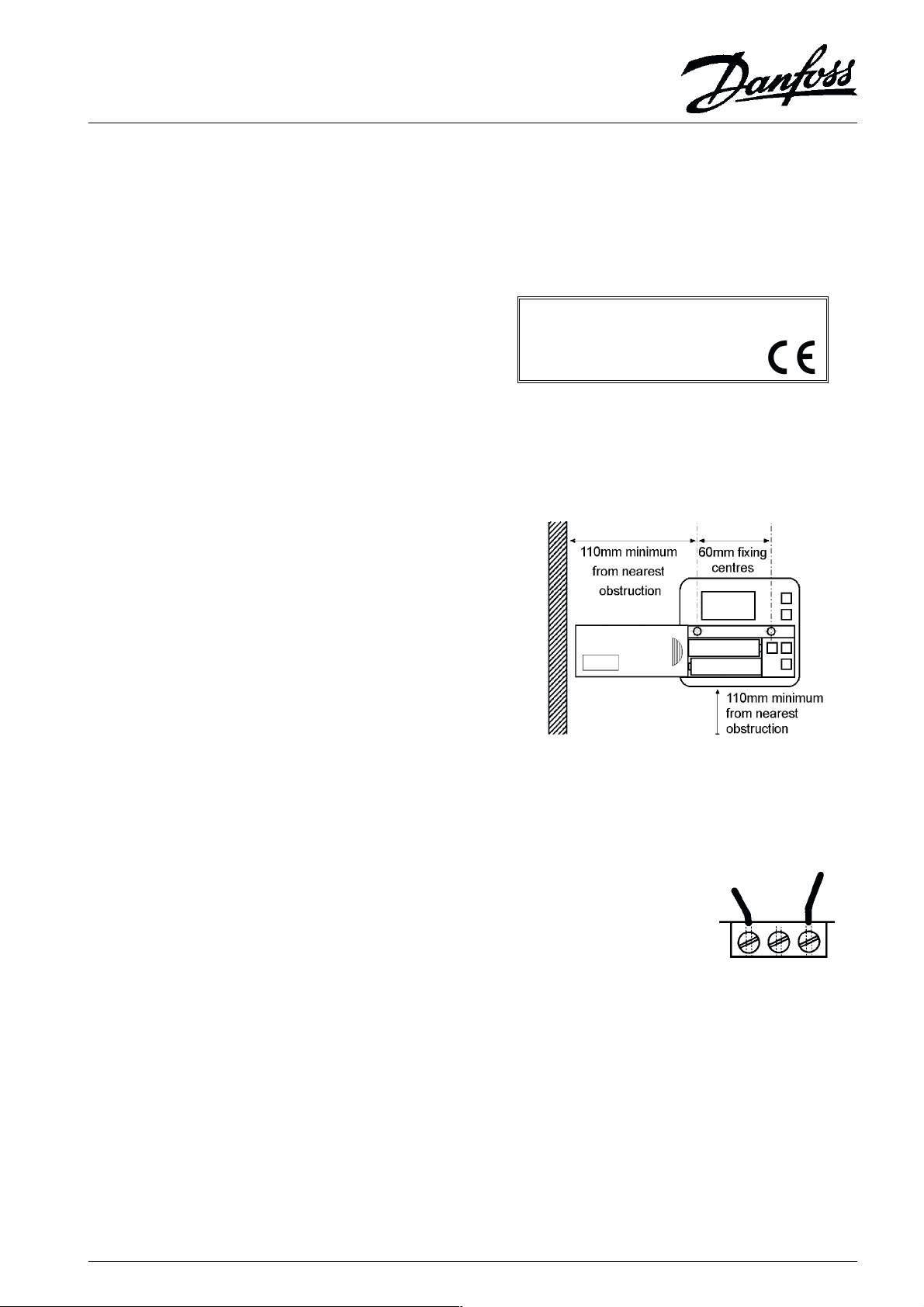
Fig.1. shows fixing hole dimensions and the clearance required for
the removal of the sliding cover, and for air flow over the sensor.
Standard M3.5 screws are used to fix the thermostat to a flush box,
or No.6 woodscrews and wall plugs of adequate length should be
used for surface fixing.
Fig.1. Fixing centre and clearances.
REPLACING AN ORDINARY ROOM THERMOSTAT
Switch OFF the power to the central
heating system.
Carefully note which wire colours are
connected to which terminal numbers
of the existing thermostat.
If the existing thermostat has no
indication of the numbers of each of
its terminals then a qualified electrician
should be called before proceeding
any further.
Remove the existing thermostats
mounting plate from the wall, and
prepare the wall to receive the
Programmable Room Thermostat. Refer to Fig.1. for dimensions.
Connect the wires to the new thermostat referring to the wiring
conversion chart overleaf.
NOTE:
Some existing thermostats will have a Neutral wire and/or an Earth
wire connected. These wires must NOT be connected to the new
terminals, but made electrically safe and coiled in the recess at the
back of the new thermostat. If in any doubt about the function of every
wire connected to the existing thermostat, call a qualified electrician for
advice.
Switched
output
ON OFF COM
3 2 1
Fig.2. Terminals on rear
of unit
Live
input
1
Page 2
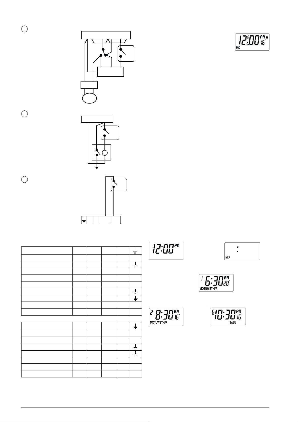
TYPICAL CIRCUIT DIAGRAMS
1
N L
ROOM STAT
REPLACEMENT
IN HEATSHARE
SYSTEM
BOILER
PUMP
2
NEUTRAL LIVE
ZONE CONTROL
3
COMBI BOILER
CONTROL
TIME CONTROL
DHW HTG
ON OFF ON
CYL.
STAT
3 PORT VALVE
MAINS
1
3
CONTROL CIRCUIT
TP
ZONE
VALVE
1
3
TP
USER INSTRUCTIONS
INITIAL START-UP
Slide the battery cover to the left to reveal
the programming buttons. Slide the cover
1
TP
3
further left to reveal the batteries. Remove
the paper insulator from between the
batteries and contacts. Reset the unit as
described below. The blank display changes
to that shown in Fig.3. (if the actual air
temperature in proximity of the unit is higher than 16°C the flame
symbol will not be displayed. The day will only appear on models
TP3 and TP5.) Slide the battery cover to the right but leave the
buttons visible
.
Fig.3. RUN mode
RESET
The unit may be reset to 12:00PM (MO) and the factory set
programme by pressing and holding down the four buttons,
temperature s and t, time + and -, until the display goes blank.
SETTING THE CLOCK
Press the PROGRAMME button once; the colon is no longer
flashing, (see Fig.4.). Use the + and - button to set the time. Hold
down a button to change the time quickly; press and release a
button to change the time by one minute. When the time and AM
or PM are correct, press the PROGRAMME button to start the
clock. On models TP2 and TP4 "Set Day" (Fig.5.) does not occur.
If you have a TP3 or TP5, now only the day and the colon are on
display, (Fig.5.). Use the + or - button to select the correct day.
Press PROGRAMME to display the first setting (Fig.6.).
REVIEWING THE EXISTING SETTINGS AND
PROGRAMMING YOUR OWN
Now each press of the PROGRAMME button shows, in, turn, the
set times, (six with the TP2 and TP4, twelve with the TP3 and TP5),
together with their associated control temperatures. Figs. 6 to 8
show the display of various settings in the sequence. The time and/
or temperature of each setting may be altered to your own
requirements using the + and - (time) and s and t (temperature)
buttons.
N L OUT IN
BOILER TERMINALS
WIRING CONVERSIONS (see key to manufacturer below)
ON OFF COM N
TP2, 3, 4, 5 3 2 1 - -
PET1 (P) TP1 (R) 1 2 L N
CM5000 (H) B C A - RD3, RD3A, (R) 2 - 1 4 R504 (R) 1 2 3 N RTC, RTM (D) RSR/M (R) 1 2 3 N
RADI (L) 2 3 1 RTE (D) 2 3 1 4 T6060B, T6160B (H) 3 4 1 2 -
ON OFF COM N
TP2, 3, 4, 5 3 2 1 - T4160B (H) 3 - 1 2 TLX 2259 (S) 1 - 3 4
TLX 2356 (S) 1 2 3 SRT2 (SW) 3 2 1 - 5
PRT1 (P) H - L N PRT2 (P) H - TL N -
Fig.4. Set time
➟➟➟➟
➟➟
➟➟➟➟
Fig.7. Setting 2.
➟➟
➟
➟➟
Fig.6. Setting 1.
➟➟➟➟➟➟
➟➟➟
➟➟➟➟➟➟
Fig.5. Set day. TP3 & TP5 only.
Fig.8. Last setting.
➟➟
➟
➟➟
RUN
(
D) Drayton
(H) Honeywell
(L) Landis & Gyr
(P) Potterton
2
(R) Randall
(S) Satchwell/Sunvic
(SO) Sopac
(SW) Switchmaster
Page 3

FACTORY PRE-SET PROGRAMMES
TP2, TP4 (Everyday)
TP3, TP5 (Monday to Friday)
Setting Time Temp. °C Setting Time Temp. °C
1 6:30am 20 1 7:00am 20
2 8:30am 16 2 10:00am 16
3 12:30pm 19 3 12:00pm 19
4 1:30pm 16 4 2:00pm 16
5 5:30pm 21 5 5:00pm 21
6 10:30pm 16 6 10:30pm 16
TP3, TP5 (Saturday to Sunday)
TYPICAL USER SET PROGRAMME
for models TP4 & TP5
BATTERY REPLACEMENT
When the batteries approach the end of
their life, a battery symbol blinks in the
display (Fig.10.). When this symbol appears
both batteries should be replaced with high
quality alkaline cells. 15 days after the
battery symbol starts to blink, the thermostat
will switch off. While the battery symbol is
blinking the batteries may be changed
without loss of time or programme.
Have the new batteries unwrapped and ready, slide the battery
cover fully off to the left, remove the old batteries and insert the
new ones WITHIN ONE MINUTE. Replace and slide close the the
battery cover. The thermostat will continue to function according to
the automatic programme. Should the display ever go blank during
normal operation the batteries will need to be renewed, the unit
reset, and the time (and day) and programmes reset if required.
Fig.11.
Setting Time Temp. °C
1 6:00am 21
2 9:00am 5
3 12:30pm 5
4 1:30pm 5
5 4:00pm 21
6 10:00pm 5
This programme provides two
heating periods, morning and
evening and effectively
switches the heating off
during the day and overnight.
LIMITS OF ADJUSTMENT FOR TIME SETTINGS
Time setting 1 can be at any time of the day or night, but would
normally be in the morning.
Each of the time settings 2 to 6 can be at any time between the
proceding setting and 1.59am.
Time settings 2 to 5 can be set later than the next setting, but doing
this changes the next setting as well....
....E.g. changing setting 2 in any of the above to 3.00pm would also
change setting 3 and 4 to 3.00pm.
This feature prevents times being set out of sequence. If you wish to
return to the pre-set programme reset the unit as described above.
EVERYDAY OPERATION
When all six or twelve time/temperature settings have been checked
and/or altered, ensure the Programmable Room Thermostat is in
the RUN mode with the colon blinking (see Fig.1.) before sliding
the cover shut.
MANUAL OVERRIDE
If you wish to temporarily change the control
temperature from the automatic setting, there
is no need to re-programme the thermostat;
just press the up or down button until the
temperature you want is displayed. An up or
down arrow will appear in the display (Fig.9.)
to remind you that you have over-ridden the
programmed temperature. The unit will revert
to programmed temperature at the start of the next programmed
event.
Fig.9.
CONSTANT LOW TEMPERATURE CONTROL
To set the thermosat to control at its low setting (5°C to 16°C
depending on model) for 24 hours a day press both s and t buttons
at the same time. The display will show the blinking colon, the low
setting and the snowflake symbol (fig 10). To return to the automatic
programme press the s and t buttons together again.
Fig.10.
3
Page 4

Danfoss Randall can accept no responsibility for possible errors in catalogues, brochures and other printed material, and reserves the right to alter its products without notice.
This also applies to products already on order provided that such alterations can be made without subsequent changes being necessary in specifications already agreed.
Danfoss Randall Limited
Ampthill Road
Bedford
MK42 9ER
Tel: (01234) 364621 Fax: (01234) 271474
Email: danfossrandall@danfoss.com
Website: www.danfoss-randall.co.uk
4
Part No: 6890 Issue 8 07/01
 Loading...