

Data sheet
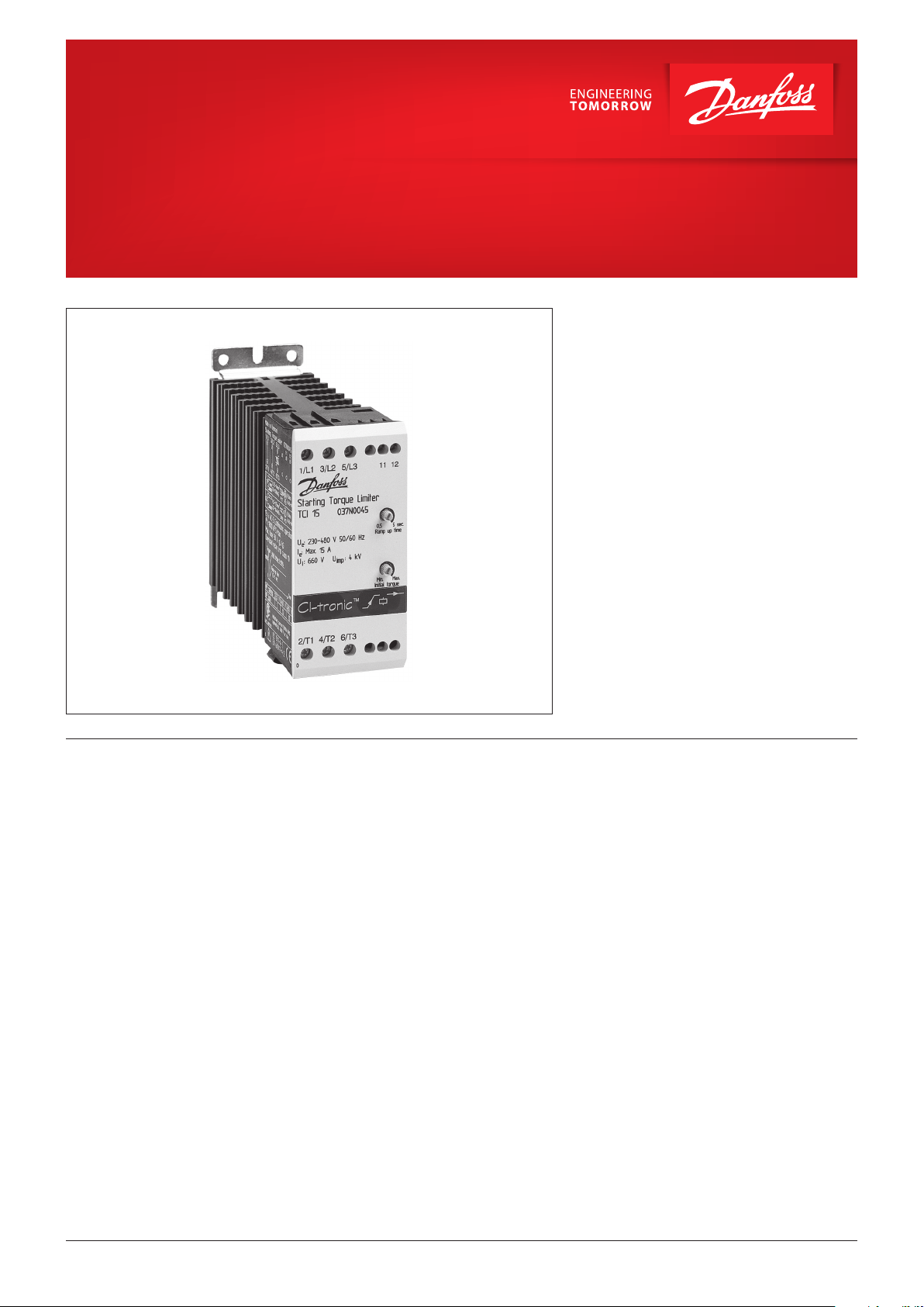
Starting Torque Limiter
Type TCI (Soft Start)
Starting Torque Limiters are designed for the soft
starting of single and tree phase AC motors.
The controller allows smooth starting of all AC
induction motors thus eliminating the damaging
eff ects of high starting torque surges.
The TCI controller is easily installed between a
standard motor starter and the motor, and
features adjustable ramp-up time and initial
torque.
Typical applications are conveyors, fans,
compressors etc.
Features • Ramp-Up time adjustable from 0.5 – 5 sec.
• Initial torque adjustable up to 85%
• Single and three phase operation
• LED Status indication
• Unlimited start/stop operations per hour
• IP20 Protection
• Compact modular design
• DIN rail mountable
• EN 60947-4-2
• CE, CSA, NRTL/C and C-tick
© Danfoss | DCS (az) | 2018.02
IC.PD.C50.E3.02 | 1
Data sheet | Starting Torque Limiter, Type TCI (Soft Start)
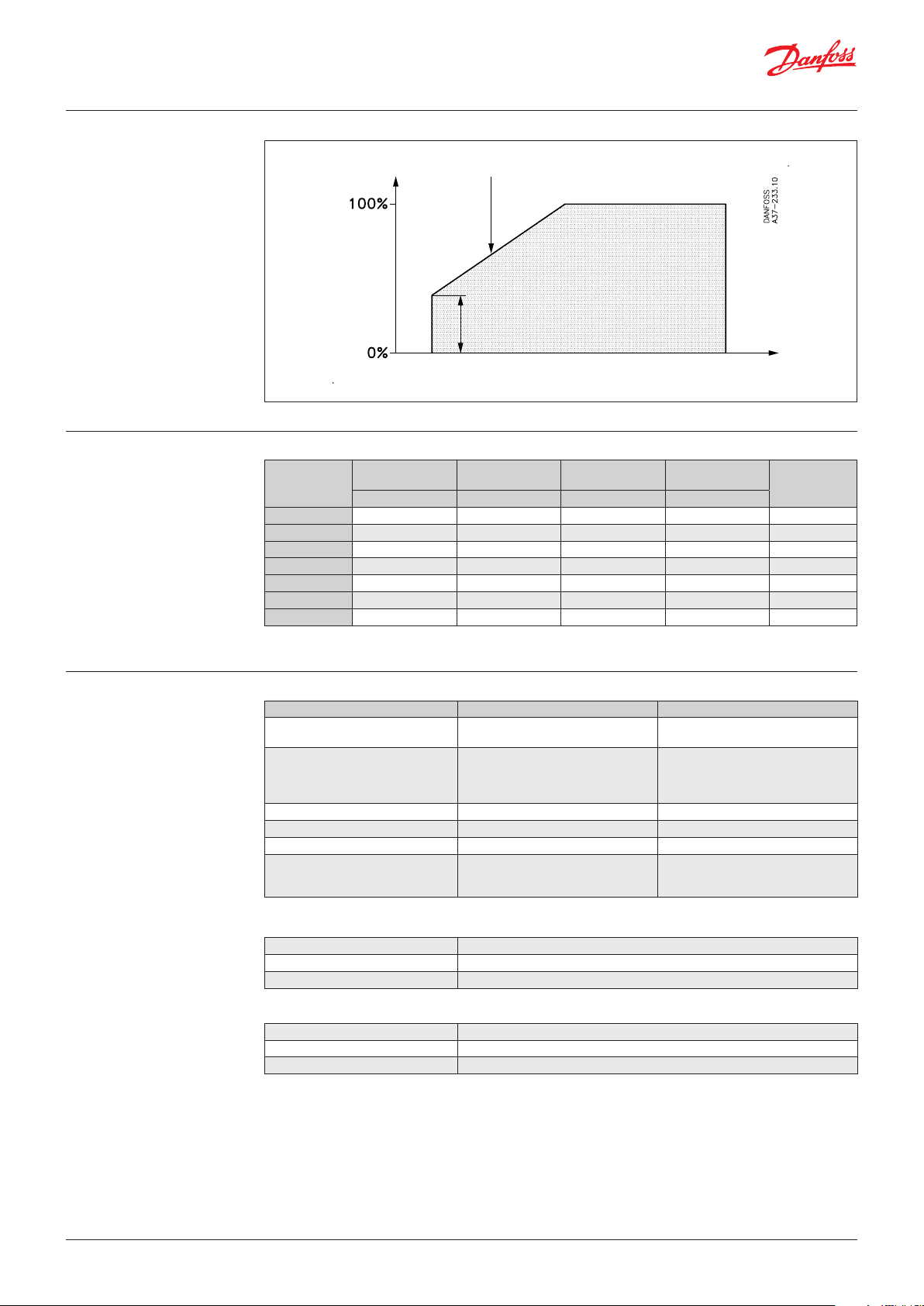
Adjustments
Selection Guide
Motor torque
(voltage)
Ramp-up time
0.5 – 5 sec.
Time
Initial torque
Up to 85% of nominal torque
Operational
Type
TCI 15 208 – 240 15 4.0 kW / 5.5 HP 45 037N0045
TCI 25 208 – 240 25 7.5 kW / 10 HP 45 037N0046
TCI 15 400 – 480 15 7.5 kW / 10 HP 45 037N0045
TCI 25 400 – 480 25 11 kW / 15 HP 45 037N0046
TCI 15 480 – 600 15 7.5 kW / 10 HP 45 037N0047
TCI 25 480 – 600 25 18.5 kW / 25 HP 45 037N0048
TCI 25 690 V AC ) 25 18.5 kW / 25 HP 45 037N0049
1
) 037N0049 for 690 V AC is not CSA/NRTL/C approved
Voltage
[V AC ] [A] [kW] [mm]
Motor current
max.
Motor power
max.
Dimensions
Code no.
Technical Data
Control Circuit Specifi cations TCI 15 TCI 25
Operational current
AC 3, AC 53a and AC 58a (motor load)
Motor size at:
208 – 240 V AC
400 – 480 V AC
480 – 600 V AC
Minimum operational current 50 mA
Overload current profi le X-Tx: 8-3
Overload relay trip class Class 10
Semiconductor protection fusing
type 1 co-ordination
type 2 co-ordination It (t = 10 ms)
15 A 25 A
0.1 – 4.0 kW (0.18 – 5 HP)
0.1 – 7,5 kW (0.18 – 10 HP)
0.1 – 7.5 kW (0.18 – 10 HP)
100 A gL/gG
6300 As
0.1 – 7,5 kW (0.18 – 10 HP)
0.1 – 11 kW (0.18 – 15 HP)
0.1 – 18 kW (0.18 – 25 HP)
100 A gL/gG
6300 As
Control specifi cations
Ramp-up time Adjustable from 0,5 – 5 seconds
Initial torque Adjustable from 0 – 85% of nominal torque
EMC immunity Meets requirements of EN50082-1 and EN 50082-2
Insulation specifi cations
Rated insulation voltage, U
Rated impulse withstand voltage, U
Installation category III
i
660 V
4 KV
imp
© Danfoss | DCS (az) | 2018.02
IC.PD.C50.E3.02 | 2

Data sheet | Starting Torque Limiter, Type TCI (Soft Start)
Technical Data
(continued)
Functional diagram
Thermal specifi cations and environment
Power dissipation, continuously duty 1 W/A
Power dissipation, intermittent duty 1 W/A. x duty cycle
Operating temperature range -5 – 40 °C
Cooling method Natural convection
Mounting Vertical (see also general mounting instructions)
Max. temperature with limited current 60 °C, see derating for high temperatures in chart below
Storage temperature range -20 – 80 °C
Protection degree / pollution degree IP20 / IP3
Materials
Housing Self extinguishing PPO UL94V1
Heat sink Aluminum black anodized
Base Electroplated steel
Line voltage (L1, L2, L3)
Motor voltage ( T1, T2, T3)
LED 1
LED 2
Soft start function As soon as the TCI controller is connected to
mains voltage, it soft starts the motor according
to the settings.
Ramp up
During ramp up, the controller will gradually
increase the voltage to the motor until it reaches
full line voltage. The motors speed will depend
on the actual load on the motor.
A motor with little or no load will reach full
speed before the voltage has reached its
maximum value.
Wiring
Single phase motor Three phase motor
Initial torque
The initial torque is used to set the initial starting
voltage. This way it is possible to adapt the
controller to an application requiring a higher
starting torque.
© Danfoss | DCS (az) | 2018.02
IC.PD.C50.E3.02 | 3

Data sheet | Starting Torque Limiter, Type TCI (Soft Start)
Overload and
Short Circuit Protection
Dimensions
[mm] (inch)
Overload and short circuit protection is easily
achieved by installing a circuit breaker on the
line side of the motor controller. Select the circuit
breaker from the table according to motor full
load current.
380 – 415 V AC
Soft start type
TCI 15
TCI 25
Motor full load
current
[A] [kA] [kA]
0.10 – 0.16 047B3140 50 50
0.16 – 0.25 047B3141 50 50
0.25 – 0.40 047B3142 50 50
0.40 – 0.63 047B3143 50 50
0.63 – 1.0 047B3144 50 50
1.0 – 1.60 047B3145 50 50
1.6 – 2.5 047B3146 50 50
2.5 – 4.0 047B3147 50 50
4.0 – 6.3 047B3148 50 50
6.3 – 10.0 047B3149 50 10
10 – 16 047B3150 10 5
14.5 – 20.0 047B3151 8 3
18 – 25 047B3152 8 3
Danfoss
CTI 25M
Be aware of the maximum prospective short
circuit current breaking capacity. For further
information please refer to the data sheet on the
circuit breaker.
Max. prospective short-circuit current Icc
Co-ordination 1 Co-ordination 2
© Danfoss | DCS (az) | 2018.02
IC.PD.C50.E3.02 | 4

Danf
already on order pro
All trademarks in this material are property of the respec
Operating at high
temperatures
If the ambient temperature exceeds 40 °C the
current must be derated according to table.
380 - 415 V AC
Ambient
temperature
°C [A] [A] [A] [A]
50 15 25 15, 100% duty-cycle 25, 100% duty-cycle
60 15 20 15, 100% duty-cycle 25, 80% duty-cycle
Continues current Duty-cycle rating (15 min. max. on-time)
TCI 15 TCI 25 TCI 15 TCI 25
Overheat protection
Mounting instructions
If required the controller can be protected
against overheating by inserting a thermostat in
the slot on the right-hand side of the controller.
Order: UP 62 thermostat 037N0050
The thermostat is connected in series with the
control circuit of the main contactor. When the
temperature of the heat sink exceeds 100 °C the
main contactor will be switched OFF. A manual
reset is necessary to restart this circuit.
oss can accept no responsibility for possible errors in catalogues, brochures and other printed material. Danfoss reserves the right to alter its products without notice. This also applies to products
vided that such alterations can be made without subsequential changes being necessary eady agreed.
© Danfoss | DCS (az) | 2018.02
tive companies. Danfoss and the Danfoss logotype are trademarks of Danfoss A/S. All rights reserved.
IC.PD.C50.E3.02 | 5
 Loading...