

Page 1
MAKING MODERN LIVING POSSIBLE
Technical Information
Series T90
Transit Mixer Drive System
powersolutions.danfoss.com
Page 2

Technical Information Series T90 Transit Mixer Drive System
Contents
Series T90
Transit Mixer Drive
Transit Mixer Pump
Series T90
Transit Mixer Motor
Series 90
General Description .......................................................................................................................................3
General Description .......................................................................................................................................4
Technical Specications ............................................................................................................................... 6
Operating Parameters ..................................................................................................................................8
System Design Parameters .......................................................................................................................10
Features ...........................................................................................................................................................11
Control ..............................................................................................................................................................13
Inatallation Drawings ..................................................................................................................................14
General Description .....................................................................................................................................17
Inatallation Drawings ..................................................................................................................................18
L1207419 • Rev BA • October 20142
Page 3

Technical Information Series T90 Transit Mixer Drive System
General Description
General
Product Features
System Features
The new Transit Mixer Drive System from Danfoss is based on more than 30 years‘
experience in the worldwide use of drum drive systems in transit mixers. Innovative
electronics suitable for mobile use, combined with reliable technology, are the result of this
development.
Danfoss oers, as a single supplier, complete systems for drum sizes from 6-18m³
[8-24 yd
3
] from one source.
The smart system resets the standard relating to the market requirements for reliability and
simple handling.
• Hydrostatic transmission
- overall size 055, 075 and 100 cm³ [3.35, 4.49 and 6.10 in3]
- rotational group proven over millions in units
- noise reduction by 12 dB (A)
- exemplary reductions in overall volume and weight
• Operating units
- external and cab-mounted station
- simple installation and wiring
- electric plug connections suitable for mobile use
- no adjustments,“Plug and Perform“
• direction of rotation and speed via latched rotary switch on the cab-mounted or
external station
• identical operating elements on the cab-mounted and external stations
• external station pushbutton: STOP/START the drum
• external station pushbutton: STOP/START the drum with the cab-mounted station
active
• cab-mounted station pushbutton: change over to external station and vice versa
• status reporting from the cab-mounted and external stations via LEDs
• active cab-mounted station during transit means the external station is switched o
• constant drum speed with variable pump-drive speed
• constant drum speed, irrespective of the loading of the drum
• exact repeatability of the drum speed by means of a latched rotary switch
• automatic maximum drum-speed limitation
A convincing, reliable and smart system solution from Danfoss which
(at present) is still missing from your transit mixer?
Contact us! Our worldwide sales organization is ready to serve you.
L1207419 • Rev BA • October 2014 3
Page 4
Technical Information Series T90 Transit Mixer Drive System
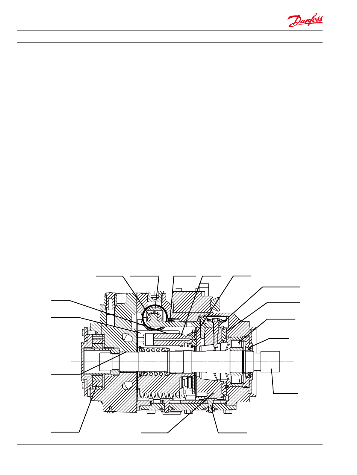
Servo piston Servo armPiston Slipper
General Description
Series T90 Family of
Pumps
Danfoss provides Series T90 as an advanced type of axial piston variable displacement
pumps for concret mixers, the development of which is based on more than 30 years
of our experience in applying our products in the global market. The new T90 axial piston variable displacement pumps are derived from the sophisticated earlier type of S90
pumps, and are suitable for extended concrete mixer applications.
Series T90 variable displacement pumps are compact, high power density units. All
models utilize the parallel axial piston/slipper concept in conjunction with a tiltable
swashplate to vary the pump’s displacement. Reversing the angle of the swashplate reverses the ow of oil from the pump and thus reverses the direction of rotation of the
motor output.
Series T90 pumps include an integral charge pump which is manually controlled to provide system replenishing and cooling oil ow, as well as control uid ow.
• Series T90 axial piston pumps are designed with the most advanced technology
• With optional sizes 055, 075, 100
• Installation: SAE standard ange
• Axial piston design of high eeciency
• Proved reliability and excellent performance
• Compact, light weight
• Worldwide sales and services
• Metric standard threads for main ports (A and B)
Design Series T90 pump cross-section
Slider block
Bushing
Cylinder block
Rear bushing
Charge pump
Feedback linkage
Cradle bearing
Roller bearing
Shaft seal
Input shaft
Cradle guideSwash plate
L1207419 • Rev BA • October 20144
Page 5
Technical Information Series T90 Transit Mixer Drive System
General Description
Pictorial Circuit Diagram
Control handle
Reversible variable
displacement pump
Input shaft
Pump swashplate
This conguration shows a hydrostatic transmission using a Series T90 axial piston
variable displacement pump and a Series 90 xed displacement motor.
Displacement control valve
Heat exchanger bypass valve
Orice check
valve
Servo control cylinder
Servo control cylinder
Heat Exchanger
Charge pressure relief valve
Multi-function valve
To
pump
case
Charge pump
Multi-function valve
Reservoir
Vacuum gauge
Purge relief valve
Fixed displacement motor
Motor swashplate
Loop ushing valve
P400053
Output shaft
working loop (high pressure)
System Schematic
M1
M4
M5
M
M2
Pump Motor
working loop (low pressure)
M3
S
Suction line
AA
BB
L2
Control uid
L2 M1
M3
L1
M2
Case drain uid
P400054
L1207419 • Rev BA • October 2014 5
Page 6
Technical Information Series T90 Transit Mixer Drive System
Technical Specications
Features
Operating Parameters
Feature Unit 055 075 100
Displacement
Flow at rated speed
(theoretical)
Torque at maximum
displacement (theoretical)
Mass moment of inertia of
rotating components
cm³
[in³]
l/min
[US gal/min]
N•m/bar
[lbf•in/1000 psi]
kg•m²
[slug•ft²]
55
[3.35]
215
[57]
0.88
[530]
0.0060
[0.0044]
75
[4.59]
236
[62]
1.19
[730]
0.0100
[0.0074]
100
[6.10]
300
[79]
1.59
[970]
0.0171
[0.0126]
Weight (with control opt. MA) kg [lb] 40 [88] 49 [108] 68 [150]
Mounting (per SAE J744) Flange SAE C
Rotation Right hand or Left hand rotation
Main ports: 4-bolts split-ange
(per ISO 6162)
mm
[in]
25.4
[1.0]
25.4
[1.0]
25.4
[1.0]
Main port conguration Twin Ports
Case drain ports
UNF thread (in.)
1.0625–12 1.0625–12 1.0625–12
(SAE O-ring boss)
Other ports SAE O-ring boss
Input Shafts Splined, 21 teeth Splined, 23 teeth Splined, 23 teeth
Parameters Unit 055 075 100
Input speed
Minimum
-1
Rated 3900 3150 3000
min
(rpm)
400 400 400
Maximum 4250 3350 3200
System pressure
Continuous
Maximum 420 [6090]
bar [psi]
400 [5800]
Minimum low loop pressure 10 [650]
Suction port pressure (charge pump inlet)
Minimum
Minimum(cold start) 0.2 [24]
(abs)
bar
[in. Hg vac.]
0.7 [9]
Case pressure
Continuous
Maximum(cold start) 5.0 [73]
bar [psi]
3.0 [44]
L1207419 • Rev BA • October 20146
Page 7

Technical Information Series T90 Transit Mixer Drive System
Technical Specications
Fluid Specications
Viscosity mm²/sec (cSt) [SUS]
Minimum 7 [49]
Recommended range 12-80 [70-370]
Maximum 1600 [7500]
Temperature range °C [°F]
Minimum -40 [-40]
Rated 104 [220]
Maximum intermittent 115 [240]
Filtration
Cleanliness 22/18/13 or higher standard ISO 4406
Eciency (suction line ltration)
=75 (β10≥2)
β
35-45
L1207419 • Rev BA • October 2014 7
Page 8

Technical Information Series T90 Transit Mixer Drive System
Operating Parameters
Input Speed
System Pressure
Minimum speed is the lowest input speed recommended during engine idle condition.
Operating below minimum speed limits the pump’s ability to maintain adequate flow
for lubrication and power transmission.
Rated speed is the highest input speed recommended at full power condition.
Operating at or below this speed should yield satisfactory product life.
System pressure is the dierential pressure between high pressure system ports. It is
the dominant operating variable aecting hydraulic unit life. High system pressure,which
results from high load, reduces expected life. Hydraulic unit life depends on the speed and
normal operating, or weighted average, pressure that can only be determined from a duty
cycle analysis.
Application pressure is the high pressure relief or pressure limiter setting normally
dened within the order code of the pump. This is the applied system pressure at which
the drive-line generates the maximum calculated pull or torque in the application.
Maximum working pressure is the highest recommended Application pressure.
Maximum working pressure is not intended to be a continuous pressure. Propel systems
with application pressures at, or below, this pressure should yield satisfactory unit life
given proper component sizing.
All pressure limits are differential pressures referenced to low loop (charge) pressure.
Subtract low loop pressure from gauge readings to compute the differential.
Case Pressure
Fluid Selection
Under normal operating conditions, the rated case pressure must not be exceeded
3 bar (44 psi). During cold start case pressure must be kept below maximum intermittent
case pressure 5 bar (73 psi). Size drain plumbing accordingly.
CCaution
Possible component damage or leakage
Operation with case pressure in excess of stated limits may damage seals, gaskets,
and/or housings, causing external leakage. Performance may also be affected since
charge and system pressure are additive to case pressure.
Ratings and performance data are based on operating with hydraulic fluids containing
oxidation, rust and foam inhibitors. These fluids must possess good thermal and
hydrolytic stability to prevent wear, erosion, and corrosion of motor components.
Never mix hydraulic fluids of different types.
Fire resistant fluids are also suitable at modified operating conditions. Please see
Hydraulic Fluids and Lubricants Technical Information, 520L0465, for more information.
The following hydraulic fluids are suitable:
• Hydraulic Oil DIN 51 524-2 - HLP
• Hydraulic Oil DIN 51 524-3 - HVLP
• SAE J183 API CD, CE and CF
L1207419 • Rev BA • October 20148
Page 9

Technical Information Series T90 Transit Mixer Drive System
Operating Parameters
Temperature and
Viscosity
Filtration System
The high temperature limits apply at the hottest point in the transmission, which is
normally the motor case drain. The system should generally be run at or below the
quoted rated temperature.The maximum intermittent temperature is based on
material properties and should never be exceeded.
Cold oil will generally not affect the durability of the transmission components, but
it may affect the ability of oil to flow and transmit power; therefore temperatures
should remain 16 °C [30 °F] above the pour point of the hydraulic fluid.The minimum
temperature relates to the physical properties of component materials. Size heat
exchangers to keep the fluid within these limits. Danfoss recommends testing to verify
that these temperature limits are not exceeded.
For maximum efficiency and bearing life, ensure the fluid viscosity remains in the
recommended range. The minimum viscosity should be encountered only during
brief occasions of maximum ambient temperature and severe duty cycle operation.
The maximum viscosity should be encountered only at cold start.
To prevent premature wear, ensure only clean fluid enters the hydrostatic transmission
circuit. A filter capable of controlling the fluid cleanliness to ISO 4406 class 22/18/13
(SAE J1165) or better, under normal operating conditions, is recommended.
These cleanliness levels can not be applied for hydraulic fluid residing in the component
housing/case or any other cavity after transport.
The selection of a filter depends on a number of factors including the contaminant
ingression rate, the generation of contaminants in the system, the required fluid
cleanliness, and the desired maintenance interval. Filters are selected to meet the
above requirements using rating parameters of efficiency and capacity.
Reservoir
Case Drain
Filter efficiency can be measured with a Beta ratio¹ (βX). For simple suction-filtered
closed circuit transmissions and open circuit transmissions with return line filtration,
a filter with a β-ratio within the range of β
= 75 (β10 ≥ 2) or better has been found to
35-45
be satisfactory.
The hydrostatic system reservoir should accommodate maximum volume changes
during all system operating modes and promote de-aeration of the fluid as it
passes through the tank. A suggested minimum total reservoir volume is 5⁄8 of the
maximum charge pump flow per minute with a minimum fluid volume equal to ½ of
the maximum charge pump flow per minute. This allows 30 seconds fluid dwell for
removing entrained air at the maximum return flow. This is usually adequate to allow
for a closed reservoir (no breather) in most applications.
Locate the reservoir outlet (charge pump inlet) above the bottom of the reservoir to
take advantage of gravity separation and prevent large foreign particles from entering
the charge inlet line. Position the reservoir inlet (fluid return) to discharge below the
normal fluid level, toward the interior of the tank. A baffle (or baffles) will further
promote de-aeration and reduce surging of the fluid.
A case drain line must be connected to one of the case outlets (L1 or L2) to return
internal leakage to the system reservoir.
L1207419 • Rev BA • October 2014 9
Page 10

Technical Information Series T90 Transit Mixer Drive System
System Design Parameters
Shaft Loads
The table below indicates the bearing life in B
hours.These data are based on the condition
10
where the pump is operated with system pressure at 240bar[3500 psi], input speed at
1800RPM, with max. displacement and no external thrust/radial shaft loads. Nearly
equal amounts of foward vs. reverse swashplate operation is experienced. The charge
pump is of standard displacement and is a standard charge pressure pump.
T90 piston pumps are designed with
bearings that can accept some external
radial and thrust loads. The external shaft
radial load limits are a function of the load
position and orientation, and operating
conditions of the motor.
Shaft life
Parameter Bearing life – B10 hours
55 22 090
75 22 970
100 22 670
The maximum allowable radial load (Re) is
based on the maximum external moment
(Me) and the distance (L) from the
mounting ange to the load. It may be
determined using the following table and
formula.
Radial/thrust load position
0°Re
90°
Re
270°
Re
Re
inTout
T
L
Formula :
Re = Me / L
180°Re
Pump swashplate
P400055
All external shaft loads aect bearing life. In applications where external shaft loads
cannot be avoided, minimize the impact by positioning the load at 90° or 270° as shown
in the gure.
Contact your Danfoss representative for an evaluation of unit bearing life, if
• you have continuously applied external loads exceeding 25 % of the maximum allowable
radial load (Re)
• or the pump swashplate is positioned on one side of center all or most of the time.
• bearing life B10 is critical.
Use of tapered output shafts or clamp-type couplings is recommended where radial
shaft loads are present.
Allowable external shaft load
Parameters 055 075 100
External moment (Me)
N•m [lbf•in]
Maximum shaft thrust in (T
Maximum shaft thrust in (T
)
in
N [lbf]
out
N [lbf]
101
[893]
3340
[750]
)
910
[204]
118
[1043]
4300
[996]
930
[209]
126
[1115]
5160
[1160]
1000
[224]
L1207419 • Rev BA • October 201410
Page 11

Technical Information Series T90 Transit Mixer Drive System
System Design Parameters
Shaft Availability and
Torque Ratings
Shaft availability and torque ratings
Shaft description 055 075 100
21 teeth
16/32 pitch spline
23 teeth
16/32 pitch spline
Filtration Suction ltration
The suction ltration is placed in the
circuit between the reservoir and inlet to
the charge pump, as shown below.
Filter with block alarm is recommended
Multi-Function Valves
1130
[10 000]
—
— —
1580
[14 000]
1580
[14 000]
Suction ltration
Hydraulic uid reservoir
To low
loop and
control
Charge pump
Ajustable
charge pressure relief valve
To pump case
Manometer
Filter
P102 003E
M1
M4
M5
M3
To control
A
A
Port
Multifunction valve
A
Bypass hex
ajustment
M
Port
B
M2
B
S
L2
Multifunction valve
Charge
pressure
relief valve
P400056
L1207419 • Rev BA • October 2014 11
Page 12

Technical Information Series T90 Transit Mixer Drive System
Features
Charge Pump
Manual Displacement
Control (MDC)
Charge ow is required on all Series T90 pumps applied in closed circuit installations. The
charge pump provides ow to make up internal leakage, maintain a positive pressure in
the main circuit, provide ow for cooling and ltration, replace any leakage losses from
external valving or auxiliary systems, and to provide ow and pressure for the control
system.
Many factors inuence the charge ow requirements and the resulting charge pump size
selection. These factors include system pressure, pump speed, pump swashplate angle,
type of uid, temperature, size of heat exchanger, length and size of hydraulic lines,control
response characteristics, auxiliary ow requirements, hydrostatic motor type, etc.When
initially sizing and selecting hydrostatic units for an application, it is frequently not
possible to have all the information necessary to accurately evaluate all aspects of charge
pump size selection.
Recommend charge pump sizes and speed limits
Charge pump size
cm³ [in³]
20 [1.20] 3600
Rated speed
min-1 (rpm)
Operation
The manual displacement control converts a mechanical input signal to a hydraulic
signal that tilts the cradle swashplate through an angular rotation varying the pump’s
displacement from full displacement in one direction to full displacement in the
opposite direction.
The manual displacement control has a mechanical feedback mechanism which moves
a servo valve in the proper relationship to the input signal and the angular position of
the swashplate. The control is designed so that the angular rotation of the swashplate
is proportional to the mechanical input signal. The control is designed with an internal
override mechanism which allows the mechanical input to be moved at a faster rate
than the movement of the swashplate without damage to the control.
Features and benets of the manual displacement control:
• Precision parts provide repeatable, accurate displacement settings with a given input
signal.
• The manual displacement control is a high gain control: With only small movement of
the control handle (input signal), the servo valve moves to full open position porting
maximum ow to the servo cylinder. This is a high response system with low input
force.
• The integral override mechanism allows rapid changes in input signal without
damaging the control mechanism.
• The double-acting servo piston is coupled to a spring centering mechanism. The
servo control valve is spring centered such that with no input signal the servo valve
is open centered and thus no uid is ported to the servo cylinder.
• Benets:
- Pump returns to neutral after prime mover shuts down.
- Pump returns to neutral if external control linkage fails at the control handle or
if there is a loss of charge pressure.
L1207419 • Rev BA • October 201412
Page 13

Technical Information Series T90 Transit Mixer Drive System
Features
Manual Displacement
Control (MDC)
Manual displacement control schematic
A – 0 – B
T P
M5
Feedback
from
swashplate
M4
P400057
External control handle requirements
• Torque required to move handle
to maximum displacement is
0.68 to 0.9 N•m [6 to 8 lbf•in].
• Torque required to hold handle
at given displacement is
0.34 to 0.57 N•m [3 to 5 lbf•in].
• Torque required to overcome the
override mechanism is 1.1 to 2.3 N•m
[10 to 20 lbf•in] with the maximum
torque required for full forward to
full reverse movement.
Cross-section
Control handle input signal
P400058
M5
M4 P
T
T
Pump displacement vs. control lever rotation
100 %
-24° to 30°
"A"
-35
Max
Displacement
-2
"0"
100 %
Handle degree
2
35
24° to 30°
P400059
Max
"B"
• Maximum allowable input torque is
17 N•m [150 lbf•in].
Control lever rotation range
a 0.5° - 4.5°
b 24° - 30°
Volumetric eciencies of the system will have impacts on the start- and end
inputcommands.
Pump output ow direction and control lever rotation
Input shaft rotation CW CCW
Handle rotation A CCW B CW A CCW B CW
Port A ow (M1) Out In In Out
Port B ow (M2) In Out Out In
Servo cylinder M5 M4 M5 M4
Refer to Installation drawings for handle connection requirements
L1207419 • Rev BA • October 2014 13
Page 14

Technical Information Series T90 Transit Mixer Drive System
Control
High Current Electric
Displacement Control
(HCEDC)
Option PH and PJ
Operation
The HCEDC uses two solenoid operated, proportional-pressure reducing valves to
control the pilot pressure to a 4-way servo valve, which ports hydraulic pressure to
either side of a double acting servo piston. The servo piston tilts the cradle swashplate,
thus varying the pump’s displacement from full displacement in one direction to full
displacement in the opposite direction. Each solenoid valve acts independently for
forward or reverse operation; therefore, the electronic controller must be able to
accommodate two independent pilot valve signal outputs.
The control has a mechanical feedback mechanism which moves the servo valve in
relation to the input signal and the angular position of the swashplate. The electrical
displacement control is designed so the angular rotation of the swashplate (pump
displacement) is proportional to the electrical input signal. Swashplate position
changes due to load variation are sensed by feedback linkage system connected to
the swashplate and control valve. This will activate the valve and supply pressure
to the servo piston, maintaining the swashplate in its commanded position. The
solenoids are equipped with manual override capability thereby allowing the pump
to be commanded to maximum angle in either direction. This is done by depressing
the plunger on the top of the solenoid. Manual operation of the control override is
intended for system troubleshooting only.
High current electric displacement control schematic
Electric Characteristics
(CCW) AS SEEN FROM SHAFT (CW) AS SEEN FROM SHAFT
Active Solenoid A B A B
Pressurized port X1 X2 X1 X2
System port A ow In Out (M1) Out (M1) In
System port B ow Out (M2) In In Out (M2)
Servo port active 2 (M5) 1 (M4) 2 (M5) 1 (M4)
Options PH PJ
Starting current “a” 350mA 178mA
Maximum current “b” 850mA 440mA
L1207419 • Rev BA • October 201414
Page 15

Technical Information Series T90 Transit Mixer Drive System
Control
High Current Electric
Displacement Control
(HCEDC)
Option PH and PJ
-Continued
PH PJ
Maximum current 850mA 440mA
PWM frequency 100 - 200 Hz
Coil resistance @ 20 ºC
9.0 W 35.6 W
The Option PJ coils have an IP 69 K environmental protection rating. The coils include a
uni-directional, polarity diode which protects downstream electronic components from
power surges originating from the coil. Therefore, care must be taken to not reverse the “+”
and “–“ terminals. Failure to do so will damage the diode and render the coil unusable. The
coils have a “1” and “2” molded in the connector for proper identication of the poles.
The Option PH (12V) and Option PJ (24V) controls can be distinguished by the color of the
shroud. The 24V Option PJ has a yellow shroud while the 12V Option PH has a blue shroud.
L1207419 • Rev BA • October 2014 15
Page 16

Technical Information Series T90 Transit Mixer Drive System
Installation Drawings
Manual Displacement Control(MDC), endcap twin portsSize 055
M2
138.8
[5.46]
134.2
[5.28]
Port S :
Charge pump inlet
1-5/16-12UN-2B
27.8
Split ange boss
Ports A and B
1.00 - 6000 psi
Per ISO 6162
M12 x 1.75
Minimum full thread 24mm
"X"
Gauge port
syetem pressure B
9/16-18UNF-2B
117.6
[4.63]
[1.09]
57.2
[2.25]
Approximate
center of
gravity
287.8
[11.33]
"Y"
246.8
[9.72]
Case drain L1
1-1/16-12UN-2B
(0.92)
Case drain L2
1-1/16-12UN-2B
156.8
[6.17]
231.8
[9.13]
7.9
47.6
[1.87]
12.7
[0.50]
33.8
[1.33]
31.3
Max.
22.86 Min.
[0.900]
Spline data:
Pitch diameter = 33.338 [1.3125]
Pressure Angle = 30°
Number of teeth= 21
120.5
Pitch = 16/32
[4.74]
ANSI B92.1-1970, class 5,
llet root, side t
Coupling must not protrude
beyond this point
M10
[10.000]
Ø28.7
[1.36]
[1.13]
Ø34.42
0
-0.05
Ø 127
"Z"
[+0.00]
[-0.02]
[Ø 5]
4x
Approximate
center of
gravity
Ø83 Min.
[Ø3.27]
95.2
57.3
[3.75]
86.24
[3.395]
Ø 14.27
[Ø 0.56]
[2.25]
+0.25
-0.13
[+0.01]
[-0.005]
89.9
[3.54]
CCW CW
57.25
[2.254]
View "Z"
43.7
[1.72]
108.7
[4.28]
Case drain L2
1-1/16-12UN-2B
mm [in]
85.2
[3.355]
Neutral
position
Gauge port M5
servo pressure
9/16-18UNF-2B
Ø 50.8±0.3
[Ø 2.0±0.01]
Maximum
displacement
B
30°
A
Maximum
displacement
View "Y"
Manual displacement control handle
dimensions
A-A
minimum
30°
minimum
Gauge port M4
servo pressure
9/16-18UNF-2B
169
[6.65]
Ø 6.73±0.13
[Ø 0.265±0.005]
Ø 25.4±0.3
[Ø 1.0±0.01]
Ø 41.3±0.3
[Ø 1.6±0.01]
73
[2.87]
View "X"
Gauge port M2
Charge pressure B
9/16-18UNF-2B
Multifunction
valve
Charge pressure
relief valve
M2
M1
B
S
A
P400060
41.7
[1.64]
3x
Gauge port M3
Charge pressure
9/16-18UNF-2B
Multifunction
valve
M3
M10
Gauge port M1
Charge pressure A
9/16-18UNF-2B
L1207419 • Rev BA • October 201416
Page 17

Technical Information Series T90 Transit Mixer Drive System
Installation Drawings
Manual Displacement Control(MDC), endcap twin portsSize 075
mm [in]
1.00 - 6000 psi
Per ISO 6162
bolt M21 x 1.75
Minimum full thread 24mm
139.6
[5.50]
129.5
[5.10]
124.2
[4.89]
27.8
[1.09]
Spline ange port
"X"
Case drain L1
1-1/16-12UN-2B
57.2
[2.25]
Approximate
center of
gravity
247.7
[247.74]
"Y"
AA
14.15
[0.557]
2
Case drain L2
242.2
[9.54]
View "Y"
1-1/16-12UN-2B
155.7
[6.13]
305.14
[12.013]
Gauge port M4
servo pressure
9/16-18UNF-2B
141.7
[5.58]
Coupling must not protrude beyond
7.9
this point
[0.31]
12.45
[12.45]
38.9
M10
[1.53]
28.5
[10.000]
Max.
Ø34.16
Min.
20
[0.787]
Spline data:
Pitch diameter =
Pressure Angle = 30°
Number of teeth= 23
Pitch = 16/32
ANSI B92.1-1970, class 5,
llet root, side t
Ø 0.8
Max.
[0.03]
[1.345]
36.513 [1.4375]
"Z"
41.7
[1.64]
[1.48]
Ø37.59
0
-0.05
[+0.00]
[-0.02]
[Ø 5]
Ø 127
4x
[Ø 0.565±0.007]
Charge pressure
relief valve
Gauge port M3
Charge pressure
9/16-18UNF-2B
155.7
[6.13]
Appr.
center of
gravity
95.5
[3.76]
Ø 14.34±0.18
57.25
[2.254]
View "Z"
94.2
[3.71]
CCW CW
4x 57.25
[2.254]
94
[3.70]
Charge pressure
relief valve
M4
M3
40.6
[1.60]
View "X"
110.7
[4.36]
Case drain L2
1-1/16-12UN-2B
Gauge port M2
Charge pressure B
9/16-18UNF-2B
Ø 94
M5
M2
B
[3.7]
Min.
91.7
[3.61]
Maximum
displacement
Neutral
position
Maximum
displacement
Gauge port M5
servo pressure
9/16-18UNF-2B
Manual displacement control handle
Ø 50.8±0.3
[Ø 2.0±0.01]
B
30°
minimum
A
30°
minimum
A
M1
Gauge port M1
Charge pressure A
9/16-18UNF-2B
dimensions
172.2
[6.78]
81.2
[3.20]
Charge pressure
relief valve
A-A
Ø 6.73±0.13
[Ø 0.265±0.005]
Ø 25.4±0.3
[Ø 1.0±0.01]
Ø 41.3±0.3
[Ø 1.6±0.01]
3x
P400061
L1207419 • Rev BA • October 2014 17
Page 18

Technical Information Series T90 Transit Mixer Drive System
Gauge port M2
Installation Drawings
Manual displacement control (MDC) endcap twin portsSize 100
mm [in]
164.7
[6.48]
153.7
[6.05]
Port S :
Charge pump inlet
1-5/8-12UN-2B
27.8
Split ange boss
Ports A and B
1.00 - 6000 psi
Per ISO 6162
M12 x 1.75
Minimum full thread 24mm
"X"
syetem pressure B
9/16-18UNF-2B
[5.45]
138.32
[1.09]
57.15
[2.25]
Approximate
center of
gravity
338.3
[13.33]
"Y"
280.4
[11.04]
Case drain L1
1-1/16-12UN-2B
(0.8)
Case drain L2
1-1/16-12UN-2B
180.3
[7.1]
277.8
[10.93]
7.9
[1.87]
12.4
[0.49]
28.5
Spline data:
Pitch diameter =
Pressure Angle = 30°
Number of teeth= 23
Pitch = 16/32
160.9
ANSI B92.1-1970, class 5,
[6.34]
llet root, side t
Coupling must not protrude
47.6
beyond this point
M10
38.9
[10.000]
[1.53]
Max.
Ø34.16
[1.345]
20 Min.
[0.787]
36.513 [1.4375]
"Z"
[1.48]
Ø37.59
0
-0.05
Ø 127
Approximate
center of
gravity
Ø101.3 Min.
[+0.00]
[-0.02]
[Ø 5]
108.8
4x
[Ø3.99]
[4.28]
101.4
Ø 14.27
[Ø 0.56]
57.25
[3.99]
+0.25
-0.13
[+0.01]
[-0.005]
[2.25]
View "Y" View "X"
Gauge port M4
servo pressure
9/16-18UNF-2B
View "Z"
107.95
[4.25]
CCW CW
57.25
[2.25]42[1.65]
Charge pressure
relief valve
119.6
[4.71]
Case drain L2
1-1/16-12UN-2B
Gauge port M2
Charge pressure B
9/16-18UNF-2B
[3.95]
100.36
Neutral
position
Gauge port M5
servo pressure
9/16-18UNF-2B
Ø 50.8±0.3
[Ø 2.0±0.01]
Maximum
displacement
B
A
Maximum
displacement
Manual displacement control handle
30°
minimum
30°
minimum
dimensions
A-A
204.6
[8.06]
Ø 6.73±0.13
[Ø 0.265±0.005]
Ø 25.4±0.3
[Ø 1.0±0.01]
Ø 41.3±0.3
[Ø 1.6±0.01]
87.66
[3.45]
Charge pressure
relief valve
M2
[1.3]
33.02
Gauge port M3
servo pressure
9/16-18UNF-2B
Charge pressure
relief valve
3x
M3
M10
B
S
A
M1
Gauge port M1
Charge pressure A
9/16-18UNF-2B
P400062
L1207419 • Rev BA • October 201418
Page 19

Technical Information Series T90 Transit Mixer Drive System
General Description
Series 90 Family of
Motors
Features
Specications
Series 90 motors also use the parallel axial piston/slipper design in conjunction with a
xed or tiltable swashplate. They can intake/discharge uid through either port; they are
bidirectional. They also include an optional loop ushing feature that provides additional
cooling and cleaning of uid in the working loop.
Parameter 055 MF 075 MF 100 MF
Types of mounting (SAE ange
size per SAE J744)
Port connections Twin, axial Twin, axial Twin
Output shaft options Spline, tapered, straight Spline, tapered, straight Spline, tapered, straight
Loop ushing
Speed sensor
Standard Optional
Parameter 055 MF 075 MF 100 MF
Swashplate Fixed Fixed Fixed
Max. displacement
cm³/rev [in³/rev]
Maximum corner power
kW [hp]
Theoretical torque
N•m/bar [lbf•in/1000 psi]
Weight
kg [lb]
Mass moment of inertia
kg•m² [slug•ft²]
SAE C SAE C SAE C
55 [3.35] 75 [4.57] 100 [6.10]
164 [220] 176[236] 224 [300]
0.88 [530] 1.19 [730] 1.59 [970]
22 [49] 26 [57] 34 [74]
0.0060
[0.0044]
0.0100
[0.0074]
0.0171
[0.0126]
Operating Parameters
Parameter Unit 055 MF 075 MF 100 MF
Speed limits
Continuous (max. disp.)
Maximum (max. disp.) 4250 3350 3200
System pressure
Continuous
Maximum 420 [6090]
Flow ratings
Rated
(max. disp., rated speed)
Maximum
(max. disp., max. speed)
Case pressure
Continuous
Maximum (cold start) 5.0 [73]
L1207419 • Rev BA • October 2014 19
-1
(rpm)
min
bar [psi]
l/min [US gal/min]
bar [psi]
3900 3150 3000
400 [5800]
215 [57] 236 [62] 300 [79]
234 [62] 251 [66] 320 [85]
3.0 [44]
Page 20

Technical Information Series T90 Transit Mixer Drive System
Installation Drawings
S90M55
189.5
[7.46]
Port “B”
73.9 [2.91]
case outlet
76.2 [3.00]
case outlet
alternate position
1
End cap ports
1.00 in dia. 6000 psi
(4) bolt split flange
type per SAE J518
(code 62) except
20.8 [0.82] minimum
full thread depth
S90M75
41.78
[1.645]
41.78
[1.645]
Port “A”
103.6
[4.08]
0.875 – 14 straight
thread O-ring boss
per SAE J514 case
outlet port L2
57.25
[2.254]
(2) places
CCW
Port“B”
73.2
[2.88]
(2) places
CW
Port“A”
mm [in]
84.8
[3.34]
minimum
73.2
[2.88]
(2) places
57.25
[2.254]
(2) places
R. 7.4 ± 0.8
[0.29 ± 0.03]
(4) places
Approximate
center of
gravity
End cap ports:
options: 1 & 8
twin ported
1.00 dia. – 6000 psi
(4) bolt split
flange type per SAE
J518 (code 62) except
20.8 [0.82] minimum
full thread depth
option: D
1.00 – 6000 psi (4) bolt
split flange type per SAE
J518 (Code 62) except
M12 x 1.75 thread 0.87
[22] minimum full thread
41.78
[1.645]
41.78
[1.645]
S90M100
End cap ports
1.00 – 6000 psi (4) bolt
split flange type per SAE
J518 (Code 62) except
20.8 [0.82] minimum
full thread depth
Port "B"
Port "A"
41.78
[1.645]
41.78
[1.645]
Port "B"
Port "A"
1.0625 – 12 straight
thread O-ring boss
per SAE J514 case
outlet port L2
1
208.8
[8.22]
113.8
[4.48]
230.9
[9.09]
0.5625 – 18 straight thread
O-ring boss per SAE J514
shaft speed sensor port
1.0625 – 12 straight thread
O-ring boss per SAE J514.
case outlet (alternate
position) port L2
128
[5.04]
1
case outlet
(alternate
position)
1
95
[3.74]
case
outlet
92.2
[3.63]
case outlet
(alternative position)
3.25
[82.6]
case
outlet
82.6
[3.25]
57.25
[2.254]
(2) places
Port "B"
57.25
[2.254]
(2) places
CCW
CCW
Port "B"
CW
CW
Port "A"
Port "A"
(2) places
94
[3.70]
minimum
73.2
[2.88]
(2) places
57.25
[2.254]
(2) places
Approximate
center of
gravity
7.4 ± 0.8
[0.29 ± 0.031]
(4) places
73.2
[2.88]
Ø100.6
[Ø3.96]
minimum
73.2
[2.88]
(2) places
57.25
[2.254]
(2) places
R. 7.37 ± 0.76
[0.29 ± 0.03]
(4) places
Approximate
center of
gravity
73.2
[2.88]
(2) places
L1207419 • Rev BA • October 201420
Page 21

Technical Information Series T90 Transit Mixer Drive System
L1207419 • Rev BA • October 2014 21
Page 22

Products we o er:
Bent Axis Motors
Closed Circuit Axial Piston
Pumps and Motors
Displays
Electrohydraulic Power
Steering
Electrohydraulics
Hydraulic Power Steering
Integrated Systems
Joysticks and Control
Handles
Microcontrollers and
Software
Open Circuit Axial Piston
Pumps
Orbital Motors
PLUS +1® GUIDE
Proportional Valves
Sensors
Steering
Transit Mixer Drives
Danfoss Power Solutions is a global manufacturer and supplier of high-quality hydraulic and
electronic components. We specialize in providing state-of-the-art technology and solutions that
excel in the harsh operating conditions of the mobile o -highway market. Building on our extensive
applications expertise, we work closely with our customers to ensure exceptional performance for a
broad range of o -highway vehicles.
We help OEMs around the world speed up system development, reduce costs and bring vehicles to
market faster.
Danfoss – Your Strongest Partner in Mobile Hydraulics.
Go to www.powersolutions.danfoss.com for further product information.
Wherever o -highway vehicles are at work, so is Danfoss.
We o er expert worldwide support for our customers, ensuring the best possible solutions for
outstanding performance. And with an extensive network of Global Service Partners, we also provide
comprehensive global service for all of our components.
Please contact the Danfoss Power Solution representative nearest you.
Comatrol
www.comatrol.com
Schwarzmüller-Inverter
www.schwarzmueller-
Local address:
inverter.com
Turolla
www.turollaocg.com
Valmova
www.valmova.com
Hydro-Gear
www.hydro-gear.com
Daikin-Sauer-Danfoss
www.daikin-sauer-danfoss.com
Danfoss
Danfoss
Power Solutions (US) Company
2800 East 13th Street
Ames, IA 50010, USA
Phone: +1 515 239 6000
Danfoss can accept no responsibility for possible errors in catalogues, brochures and other printed material. Danfoss reserves the right to alter its products without notice. This also applies to products
already on order provided that such alterations can be made without subsequential changes being necessary in specifications already agreed.
All trademarks in this material are property of the respective companies. Danfoss and the Danfoss logotype are trademarks of Danfoss A/S. All rights reserved.
L1207419 • Rev BA • October 2014 www.danfoss.com © Danfoss A/S, 2014
Danfoss
Power Solutions GmbH & Co. OHG
Krokamp 35
D-24539 Neumünster, Germany
Phone: +49 4321 871 0
Danfoss
Power Solutions ApS
Nordborgvej 81
DK-6430 Nordborg, Denmark
Phone: +45 7488 2222
Power Solutions
(Shanghai) Co. Ltd.
Building #22, No. 1000 Jin Hai Rd
Jin Qiao, Pudong New District
Shanghai, China 201206
Phone: +86 21 3418 5200
 Loading...