

Page 1

Technical Information
Series T90 Axial Piston Motors
Size 055/075/100
www.danfoss.com
Page 2
Technical Information
Series T90 Axial Piston Motors
Revision history Table of revisions
Date Changed Rev
August 2021 Updated System pressure 0302
July 2021 Updated System pressure 0202
October 2020 4th edition - DITA layout, changed document number from BC00000366 0201
October 2017 3rd edition 0102
May 2016 2nd edition 0101
February 2016 1st edition AA
2 | © Danfoss | August 2021 BC195786485247en-000302
Page 3

Technical Information
Series T90 Axial Piston Motors
Contents
General Description
Series T90 Family of Pumps and Motors.................................................................................................................................. 4
Fixed Displacement Motor, SAE Mount....................................................................................................................................5
Series T90 Pictorial Circuit Diagram...........................................................................................................................................6
System Schematic............................................................................................................................................................................ 6
Technical Specifications
Overview..............................................................................................................................................................................................7
Features and Options......................................................................................................................................................................7
Specifications.....................................................................................................................................................................................7
Operating Parameters.....................................................................................................................................................................8
Fluid Specification............................................................................................................................................................................8
Operating Parameters
Input Speed........................................................................................................................................................................................ 9
Independent Braking System................................................................................................................................................. 9
System Pressure................................................................................................................................................................................9
Case Pressure...................................................................................................................................................................................10
Temperature.................................................................................................................................................................................... 10
Viscosity.............................................................................................................................................................................................10
System Design Parameters
Fluid and Filtration........................................................................................................................................................................ 11
Independent Braking System....................................................................................................................................................11
Reservoir............................................................................................................................................................................................11
Overpressure Protection............................................................................................................................................................. 12
Case Drain.........................................................................................................................................................................................12
Sizing Equations............................................................................................................................................................................. 12
Formulas...................................................................................................................................................................................... 12
External Shaft Loading and Bearing Life................................................................................................................................12
Applications with external shaft loads..............................................................................................................................13
Features and Options
Loop Flushing..................................................................................................................................................................................15
Speed Sensor...................................................................................................................................................................................16
Shaft Options...................................................................................................................................................................................18
Installation Drawings
T90M55 Fixed Motor SAE Mount..............................................................................................................................................19
T90M75 Fixed Motor SAE Mount..............................................................................................................................................21
T90M100 Fixed Motor SAE Mount........................................................................................................................................... 23
©
Danfoss | August 2021 BC195786485247en-000302 | 3
Page 4

Technical Information
Series T90 Axial Piston Motors
General Description
Series T90 Family of Pumps and Motors
Series T90 hydrostatic pumps and motors can be applied together or combined with other products in a
system to transfer and control hydraulic power. They are intended for closed circuit applications.
Series T90 variable displacement pumps are compact, high power density units. All models utilize the
parallel axial piston/slipper concept in conjunction with a tiltable swashplate to vary the pump's
displacement. Reversing the angle of the swashplate reverses the flow of oil from the pump and thus
reverses the direction of rotation of the motor output.
Series T90 pumps include an integral charge pump to provide system replenishing and cooling oil flow,
as well as control fluid flow. They also feature a range of auxiliary mounting pads to accept auxiliary
hydraulic pumps for use in complementary hydraulic systems. A complete family of control options is
available to suit a variety of control systems (mechanical, hydraulic, electric).
Series T90 motors also use the parallel axial piston/slipper design in conjunction with a fixed swashplate.
They can intake/discharge fluid through either port; they are bidirectional. They also include an optional
loop flushing feature that provides additional cooling and cleaning of fluid in the working loop.
Series T90 – advanced technology today
•
Three sizes of variable displacement pumps
•
Three sizes of fixed displacement motors
•
SAE mount configurations
•
Efficient axial piston design
•
Proven reliability and performance
•
Compact, lightweight
•
Worldwide sales and service
•
4 | © Danfoss | August 2021 BC195786485247en-000302
Page 5
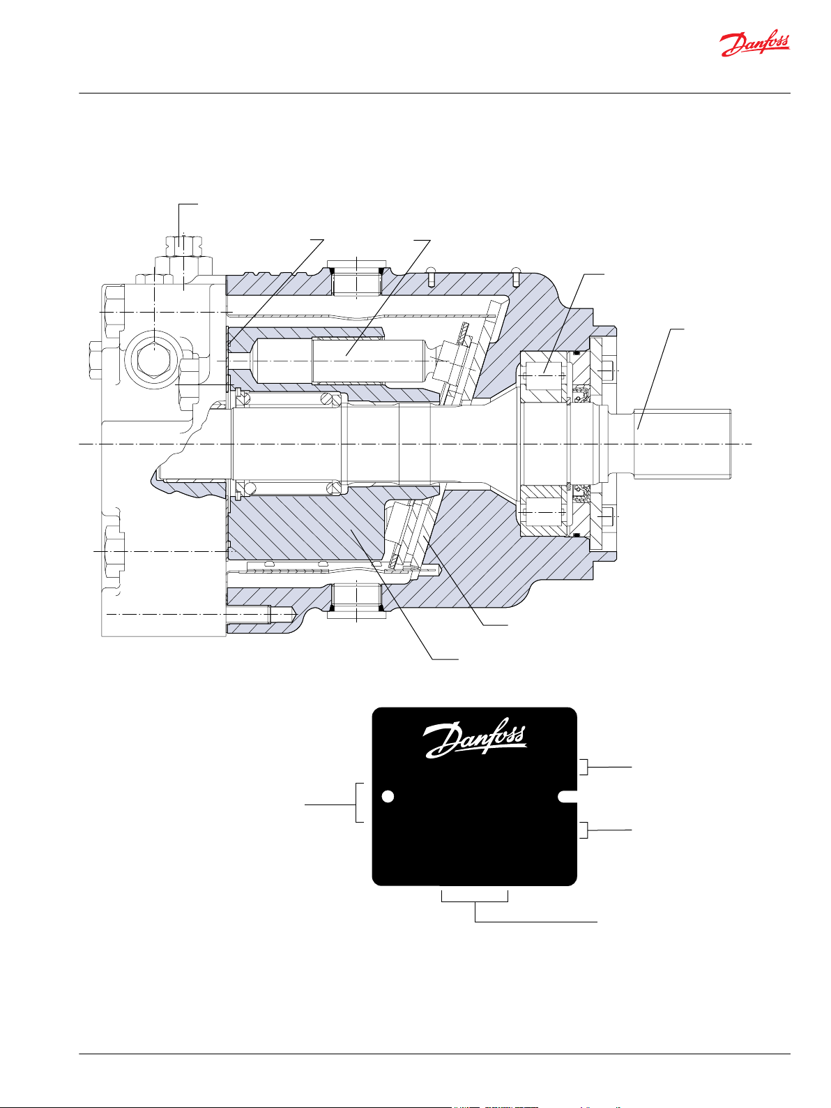
P100 490E
Loop flushing valve
Valve plate Piston
Roller bearing
Output shaft
Fixed swashplate
Cylinder block
Model-No./Ident-No.
Model Code
Serial-No.
Made in P.R.C
Model
Number
Serial
Number
Model
Code
Place of Manufacture
C - 00 - 13 - 67890
501829
P400717
T90 M 055 NC 0 N 8 N 0
C6 W 00 MBX 00 00 F0
Technical Information
Series T90 Axial Piston Motors
General Description
Fixed Displacement Motor, SAE Mount
Cross section
Name plate
©
Danfoss | August 2021 BC195786485247en-000302 | 5
Page 6
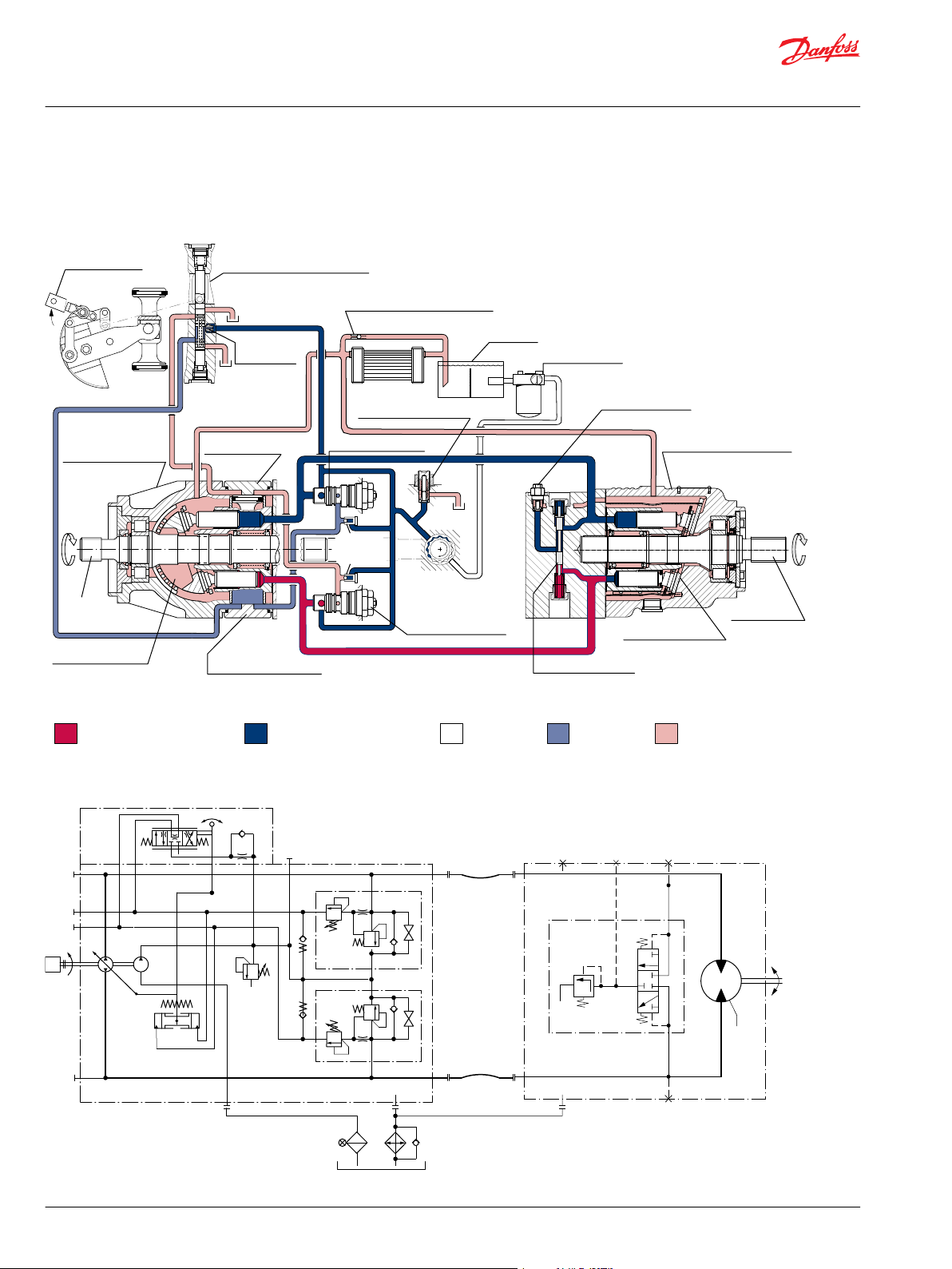
Pump Motor
Working loop (low pressure)
Control fluid
Suction line
Case drain fluid
Working loop (high pressure)
Motor swashplate
Loop flushing valve
Displacement control valve
Heat exchanger bypass valve
Reservoir
Vacuum gauge
Purge relief valve
Fixed displacement motor
Output shaft
Multi-function valve
Charge pump
To
pump
case
Servo
pressure
relief valves
Servo control cylinder
Pump swashplate
Input shaft
Reversible variable
displacement pump
Servo control cylinder
Heat exchanger
Multi-function valve
Charge pressure relief valve
Orificed check
valve
Control handle
P102 000
M
BB
L2
M2
M1
M4
M5
M3
A A
S
L2 M1
M2
L1
M3
P104 286E
Technical Information
Series T90 Axial Piston Motors
General Description
Series T90 Pictorial Circuit Diagram
The circuit diagram shows a hydrostatic transmission using a Series T90 axial piston variable
displacement pump and a Series T90 fixed displacement motor.
System Schematic
6 | © Danfoss | August 2021 BC195786485247en-000302
Page 7
Technical Information
Series T90 Axial Piston Motors
Technical Specifications
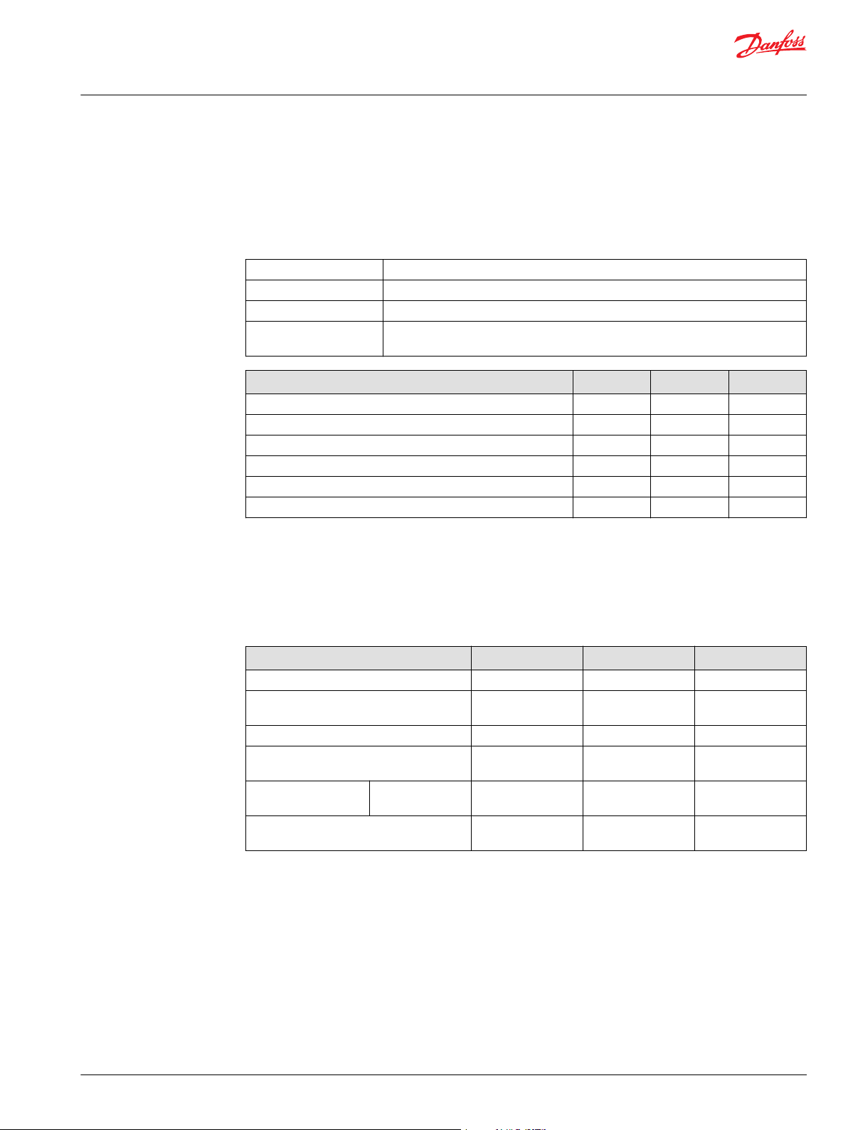
Overview
Specifications for the Series T90 motors are listed here for quick reference. For definitions and additional
information, see Operating Parameters on page 8.
Features and Options
Motor type In-line, axial piston, closed loop, positive displacement motors
Direction of rotation Bi-directional, see outline drawings for rotation vs. flow direction information
Installation position Discretionary: Housing must be filled with hydraulic fluid
Other system requirements Independent braking system, overpressure protection, suitable reservoir, proper
Parameter 055 MF 075 MF 100 MF
Types of mounting (SAE flange size per SAE J744) SAE C SAE C SAE C
Port connections Twin, axial Twin, axial Twin, axial
Output shaft options Spline Spline Spline
Control options — — —
Loop flushing • • •
Speed sensor o o o
filtration
Specifications
• Standard
o Optional
— Not available / not applicable
Parameter 055 MF 075 MF 100 MF
Swashplate Fixed Fixed Fixed
Max. displacement
cm³/rev [in³/rev]
Maximum corner power kW [hp] 142 [190] 175 235] 224 [300]
Theoretical torque
N•m/bar [lbf•in/1000 psi]
Weight
kg [lb]
Mass moment of inertia
kg•m² [slug•ft²]
SAE 22 [49] 26 [57] 34 [74]
55 [3.35] 75 [4.57] 100 [6.10]
0.88
[530]
0.0060 [0.0044] 0.0096 [0.0071] 0.0150 [0.0111]
1.19
[730]
1.59
[970]
©
Danfoss | August 2021 BC195786485247en-000302 | 7
Page 8
Technical Information
Series T90 Axial Piston Motors
Technical Specifications
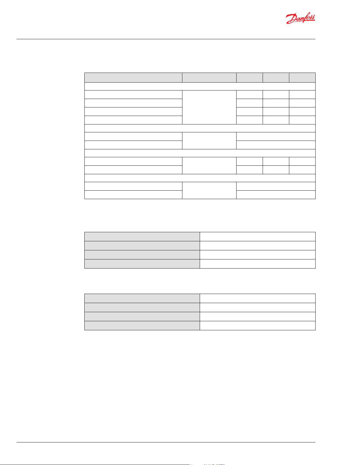
Operating Parameters
Parameter Unit 055 MF 075 MF 100 MF
Speed limits
Continuous (max. disp.) min-1(rpm) 3500 3150 3000
Maximum (max. disp.) 3700 3350 3200
Continuous (min. disp.) — — —
Maximum (min. disp.) — — —
System pressure
Maximum working pressure bar [psi] 350 [5076]
Maximum pressure 420 [6092]
Flow ratings
Rated (max. disp., rated speed) l/min [US gal/min] 175 [46] 236 [62] 300 [79]
Maximum (max. disp., max. speed) 185 [49] 251 [66] 320 [85]
Case pressure
Continuous bar [psi] 3 [44]
Maximum (cold start) 5 [73]
Fluid Specification
Viscosity
Intermittent
Minimum
Recommended range
Maximum (cold start)
1)
= Short term t < 1 min per incident and not exceeding 2 % of duty cycle based load-life.
1)
5 [42 ]
7 [49 ]
12 – 80 [66 – 370 ]
1600 [7500 ]
Temperature
Minimum (cold start)
Maximum continuous
Recommended range
Maximum Intermittent
1)
Cold start = Short term t > 3 min, p ≤ 50 bar [725 psi], n ≤ 1000 min-1 (rpm).
2)
At the hottest point, normally case drain port.
1)
2)
-40°C [-40°F]
104°C [220°F]
60 – 85°C [140 – 185°F]
115°C [240°F]
8 | © Danfoss | August 2021 BC195786485247en-000302
Page 9

W
Technical Information
Series T90 Axial Piston Motors
Operating Parameters
Input Speed
Minimum
speed
Rated speed is the highest input speed recommended at full power condition. Operating at or
Maximum
speed
During hydraulic braking and downhill conditions, the prime mover must be capable of providing
sufficient braking torque in order to avoid pump over speed. This is especially important to consider for
turbo-charged and Tier 4 engines.
For more information please see Pressure and Speed Limits, BC152886484313, when determining speed
limits for a particular application.
Independent Braking System
is the lowest input speed recommended during engine idle condition. Operating below
minimum speed limits the pump’s ability to maintain adequate flow for lubrication and
power transmission.
below this speed should yield satisfactory product life.
Operating conditions between rated and maximum speed should be restricted to less
than full power and to limited periods of time.
is the highest operating speed permitted. Exceeding maximum speed reduces product
life and can cause loss of hydrostatic power and braking capacity. For most drive
systems, maximum unit speed occurs during downhill braking or negative power
conditions.
Warning
Never exceed the maximum speed limit under any operating conditions.
System Pressure
Unintended vehicle or machine movement hazard. Exceeding maximum speed may cause a loss of
hydrostatic drive line power and braking capacity.
Machine manufacturer is responsible to provide a braking system, redundant to the hydrostatic
transmission, sufficient to stop and hold the vehicle or machine in the event of hydrostatic drive power
loss. The braking system must also be sufficient to hold the machine in place when full power is applied.
Hydraulic unit life depends on the speed and normal operating — or weighted average — pressure that
can only be determined from a duty cycle analysis.
System pressure is the differential pressure between high pressure system ports. It is the dominant
operating variable affecting hydraulic unit life. High system pressure, which results
from high load, reduces expected life.
Application
pressure
Maximum
working
pressure
is the high pressure relief or pressure limiter setting normally defined within the
order code of the pump. This is the applied system pressure at which the drive line
generates the maximum calculated pull or torque in the application.
is the highest recommended application pressure and is not intended to be a
continuous pressure. Propel systems with application pressures at, or below this
pressure should yield satisfactory unit life given proper component sizing.
Application pressures above maximum working pressure will only be considered
with duty cycle analysis and factory approval.
Pressure spikes are normal and must be considered when reviewing maximum
working pressure.
©
Danfoss | August 2021 BC195786485247en-000302 | 9
Page 10

Technical Information
Series T90 Axial Piston Motors
Operating Parameters
Case Pressure
Temperature
Maximum
pressure
Minimum low
loop pressure
Under normal operating conditions, the rated case pressure must not be exceeded. During cold start case
pressure must be kept below maximum intermittent case pressure. Size drain plumbing accordingly.
The auxiliary pad cavity of axial pumps configured without integral charge pumps is referenced to case
pressure. Units with integral charge pumps have auxiliary mounting pad cavities referenced to charge
inlet (vacuum).
Possible component damage or leakage.
Operation with case pressure in excess of stated limits may damage seals, gaskets, and/or housings,
causing external leakage. Performance may also be affected since charge and system pressure are
additive to case pressure.
The high temperature limits apply at the hottest point in the transmission, which is normally the motor
case drain. The system should generally be run at or below the quoted rated temperature.
The maximum intermittent temperature is based on material properties and should never be
exceeded.
Cold oil will generally not affect the durability of the transmission components, but it may affect the
ability of oil to flow and transmit power; therefore temperatures should remain 16 °C [30 °F] above the
pour point of the hydraulic fluid.
The minimum temperature relates to the physical properties of component materials.
Size heat exchangers to keep the fluid within these limits. Danfoss recommends testing to verify that
these temperature limits are not exceeded.
is the highest intermittent pressure allowed under any circumstances. Applications
with applied pressures between rated and maximum require factory approval with
complete application, duty cycle, and life expectancy analysis.
must be maintained under all operating conditions to avoid cavitation.
All pressure limits are differential pressures referenced to low loop (charge) pressure.
Subtract low loop pressure from gauge readings to compute the differential.
Viscosity
For maximum efficiency and bearing life, ensure the fluid viscosity remains in the recommended range.
The minimum viscosity should be encountered only during brief occasions of maximum ambient
temperature and severe duty cycle operation.
The maximum viscosity should be encountered only at cold start.
10 | © Danfoss | August 2021 BC195786485247en-000302
Page 11

W
Technical Information
Series T90 Axial Piston Motors
System Design Parameters
Fluid and Filtration
To prevent premature wear, it is imperative that only clean fluid enter the hydrostatic transmission
circuit. A filter capable of controlling the fluid cleanliness to ISO 4406 class 22/18/13 (SAE J1165) or better
under normal operating conditions is recommended.
The filter may be located either on the inlet (suction filtration) or discharge (charge pressure filtration)
side of the charge pump. The selection of a filter depends on a number of factors including the
contaminant ingression rate, the generation of contaminants in the system, the required fluid cleanliness,
and the desired maintenance interval. Filters are selected to meet the above requirements using rating
parameters of efficiency and capacity.
Filter efficiency may be measured with a Beta ratio (βX).
Filter βx-ratio is a measure of filter efficiency defined by ISO 4572. It is defined as the ratio of the number
of particles greater than a given diameter (“x” in microns) upstream of the filter to the number of these
particles downstream of the filter.
For simple suction-filtered closed circuit transmissions and open circuit transmissions with return line
filtration, a filter with a β-ratio within the range of β
satisfactory. For some open circuit systems, and closed circuits with cylinders being supplied from the
same reservoir, a considerably higher filter efficiency is recommended. This also applies to systems with
gears or clutches using a common reservoir. For these systems, a charge pressure or return filtration
system with a filter β-ratio in the range of β
Because each system is unique, only a thorough testing and evaluation program can fully validate the
filtration system. Please see Design Guidelines for Hydraulic Fluid Cleanliness BC152886482150, for more
information.
= 75 (β10 ≥ 2) or better has been found to be
35-45
= 75 (β10 ≥ 10) or better is typically required.
15-20
Independent Braking System
Reservoir
Warning
Unintended vehicle or machine movement hazard.
The loss of hydrostatic drive line power, in any mode of operation (forward, neutral, or reverse) may cause
the system to lose hydrostatic braking capacity. You must provide a braking system, redundant to the
hydrostatic transmission, sufficient to stop and hold the vehicle or machine in the event of hydrostatic
drive power loss.
The reservoir should be designed to accommodate maximum volume changes during all system
operating modes and to promote de-aeration of the fluid as it passes through the tank.
A suggested minimum total reservoir volume is 5/8 of the maximum charge pump flow per minute with a
minimum fluid volume equal to 1/2 of the maximum charge pump flow per minute. This allows 30
seconds fluid dwell for removing entrained air at the maximum return flow. This is usually adequate to
allow for a closed reservoir (no breather) in most applications.
The reservoir outlet to the charge pump inlet should be above the bottom of the reservoir to take
advantage of gravity separation and prevent large foreign particles from entering the charge inlet line. A
125 mm screen over the outlet port is recommended.
The reservoir inlet (fluid return) should be positioned so that flow to the reservoir is discharged below the
normal fluid level, and also directed into the interior of the reservoir for maximum dwell and efficient deaeration. A baffle (or baffles) between the reservoir inlet and outlet ports will promote de-aeration and
reduce surging of the fluid.
©
Danfoss | August 2021 BC195786485247en-000302 | 11
Page 12

Based on SI units
Input flow Q = (l/min)
Output torque M = (N•m)
Output power P = (kW)
Motor speed n = (min
-1
(rpm))
Based on US units
Input f low Q = (US gal/min)
Output torque M = (lbf•in)
Output power P = (hp)
Motor speed n = (min
-1
(rpm))
SI units [US units]
Vg= Displacement per revolution cm3/rev [in3/rev]
pO= Outlet pressure bar [psi]
pi= Inlet pressure bar [psi]
∆p = pO– pi(system pressure) bar [psi]
n = Speed min-1(rpm)
ηv= Volumetric eff ciency
ηm= Mechanical eff ciency
ηt= Overall eff ciency (ηv• ηm)
Variables
Vg• n
1000 • η
v
Q • 1000 • η
v
V
g
Vg• n
231 • η
v
Vg• ∆p • η
m
20 • π
Q • ∆p • η
t
600
Vg• ∆p • η
m
2 • π
Q • ∆p • η
t
1714
Q • 231• η
v
V
g
Technical Information
Series T90 Axial Piston Motors
System Design Parameters
Overpressure Protection
Series T90 motors (as well as other system components) have pressure limitations. As Series 90 motors
are not equipped with overpressure protection, it is necessary that relief valves or pressure limiters are
present elsewhere in the high pressure circuit to protect components from excessive pressures.
Series T90 pumps are designed with a sequenced pressure limiting system and high pressure relief
valves. When the preset pressure is reached, the pressure limiter system acts to rapidly de-stroke the
pump in order to limit the system pressure. For unusually rapid load application, the high pressure relief
valve function is available to also limit the pressure level. Refer to publication Series T90 Pumps Technical
Information Manual BC152886484177 for more information.
For systems with relief valves only, high pressure relief valves are intended for transient overpressure
protection and are not intended for continuous pressure control. Operation over relief valves for
extended periods of time may result in severe heat build up. High flows over relief valves may result in
pressure levels exceeding the nominal valve setting and potential damage to system components.
Case Drain
A case drain line must be connected to one of the case outlets (L1 or L2) to return internal leakage and
loop flushing flow to the system reservoir. The higher of the two case outlets should be used to promote
complete filling of the case. Since case drain fluid is typically the hottest fluid in the system, it is
advantageous to return this flow through the heat exchanger.
Sizing Equations
The following equations are helpful when sizing hydraulic motors. Generally, the sizing process is
initiated by an evaluation of the machine system to determine the required motor speed and torque to
perform the necessary work function. Refer to Selection of drive line components BLN-9985, for a more
complete description of hydrostatic drive line sizing. First, the motor is sized to transmit the maximum
required torque. The pump is then selected as a flow source to achieve the maximum motor speed.
Formulas
External Shaft Loading and Bearing Life
12 | © Danfoss | August 2021 BC195786485247en-000302
In vehicle propel drives with no external shaft loads where the system pressure is changing direction and
magnitude regularly and the operating parameters are within the limits, the normal L20 bearing life (80%
survival) will exceed the hydraulic life of the unit.
Page 13

P108 674E
Me
Re
Fb
L
0 R
e
180 R
e
90 R
e
270 R
e
Axis of swashplate
rotation
End view
of shaft
P101 433
Technical Information
Series T90 Axial Piston Motors
System Design Parameters
In non-propel drives such as vibratory drives, conveyor drives or fan drives, the operating pressure is
often constant. These drives have unique duty cycles compared to a propel drive. In these types of
applications a bearing life review is recommended.
In a bearing life analysis the following parameters are considered: Speed, pressure and external loads.
Other factors that affect life include fluid type, viscosity and cleanliness.
Shaft loading parameters
Re Maximum radial side load
Me Maximum external moment
L Distance from mounting flange to point of load
Shaft loading
External shaft load orientation
Applications with external shaft loads
Avoid external thrust (axial) loads in either direction whenever possible. Thrust loads could reduce the
bearing life in applications with low delta system pressure or when present in combination with radial
loading or bending moments.
External loads are found in applications where the motor is driven with a radial load on the shaft (i.e. belt
or gear driven) as well as installations with misalignment or improper concentricity between the motor
and drive coupling. All external loads will act to reduce the normal bearing life of a motor.
In applications where external radial shaft loads cannot be avoided, minimize the impact on bearing life
by orienting the load to the 180° position as shown in the figure below when possible. Use tapered
output shafts or clamped-type couplings where radial shaft loads are present.
Maximum allowable external shaft loads
Displacement cm3 055 075 100
External moment Me N•m 101 118 126
©
Danfoss | August 2021 BC195786485247en-000302 | 13
* No tapered shaft available
Page 14

Technical Information
Series T90 Axial Piston Motors
System Design Parameters
If continuous applied radial loads exceed 25% of the maximum allowable or thrust (axial) loads are
present, contact your Danfoss representative for a bearing life evaluation.
14 | © Danfoss | August 2021 BC195786485247en-000302
Page 15

W
Technical Information
Series T90 Axial Piston Motors
Features and Options
Loop Flushing
Warning
Unintended vehicle or machine movement hazard.
Excessive motor loop flushing flow may result in the inability to build required system pressure in some
conditions. Maintain correct charge pressure under all conditions of operation to maintain pump control
performance in hydrostatic systems.
An integral non-adjustable loop flushing valve is incorporated into Series 90 motors. Installations that
require fluid to be removed from the low pressure side of the system circuit because of cooling
requirements or contamination removal will benefit from loop flushing.
The integral loop flushing valve is equipped with an orificed charge pressure relief valve designed with a
cracking pressure of 16 bar [232 psi]. Valves are available with several orifice sizes to meet the flushing
flow requirements of all system operating conditions.
The total system charge pump flow should be of sufficient volume to accommodate:
The number of motors in the system
•
System efficiency under worst case conditions
•
Pump control requirements
•
External needs
•
Although charge pump sizing requires the consideration of many system variables, the following table
gives a recommendation of what charge pump displacement may be required to accommodate the
flushing flow of each available charge relief valve orifice.
©
Danfoss | August 2021 BC195786485247en-000302 | 15
Page 16

0
5
[1.3]10[2.6]
15
[4.0]
20
[5.3]
Low system pressure minus case pressure
bar [psi]
25
[6.6]
30
[8.0]
35
[9.2]
40
[10.6]
[508]
35
[363]
25
[218]
15
[73]
5
P109278
E4 E6 F0 F3 G0 G3
H0
N4
N6
A0
A3
B0
B3
C0
16 bar cracking pressure
13 bar cracking pressure
Case flow l/min [US gal/min]
P001 830
BA
Loop flushing
relief valve
Loop flushing
shuttle v alve
P101 426E
Technical Information
Series T90 Axial Piston Motors
Features and Options
Loop flushing flow curves
Recommended charge pump displacement
13 bar ± 8.5% cracking
Orifice option
Charge pump displacement
16 bar ± 8.5% cracking
pressure
N4
pressure
E4 8 cm³ [0.49 in³]
N6 E6 8 cm³ [0.49 in³]
A0 F0 11 cm³ [0.67 in³]
A3 F3 14 cm³ [0.85 in³]
B0 G0 17 or 20 cm³ [1.04 or 1.22 in³]
B3 G3 26 cm³ [1.59 in³]
C0 H0 34, 37, or 65 cm³ [2.07, 2.26, or 3.97 in³]
Schematic diagram of loop flushing valve
Speed Sensor
16 | © Danfoss | August 2021 BC195786485247en-000302
An optional speed sensor for direct measurement of speed is available. This sensor may also be used to
sense the direction of rotation.
A special magnetic ring is pressed onto the outside diameter of the cylinder block and a Hall effect sensor
is located in the motor housing. The sensor accepts supply voltage and outputs a digital pulse signal in
response to the speed of the ring. The output changes its high/low state as the north and south poles of
the permanently magnetized speed ring pass by the face of the sensor. The digital signal is generated at
frequencies suitable for microprocessor based controls.The sensor is available with different connectors
(see below).
Loop flushing valve cross section
Page 17

Speed sensor
Magnetic ring
Cylinder block
P101 429E
P001 492
Red
White
Black
Green
P002 108E
Technical Information
Series T90 Axial Piston Motors
Features and Options
Speed Sensor
Specifications
Supply voltage* 4.5 to 8.5 VDC
Supply voltage (regulated) 15 VDC max.
Required current 12 mA at 5 VDC, 1 Hz
Max. current 20 mA at 5 VDC, 1 Hz
Max. frequency 15 kHz
Voltage output (high) Supply -0.5 V min.
Voltage output (low) 0.5 V max.
Temperature range -40° to 110°C [-40° to 230°F]
* Do not energize the 4.5 to 8.5 VDC sensor with 12 VDC battery voltage. Use a regulated power supply. If
you need to energize the sensor with battery voltage, contact your Danfoss representative for a special
sensor.
Pulse frequency
055 075 100
Pulse per revolution 52 58 63
Speed sensor with Turck® Eurofast connector
Speed sensor with Packard® Weather-Pack connector
©
Danfoss | August 2021 BC195786485247en-000302 | 17
Page 18

Technical Information
Series T90 Axial Piston Motors
Features and Options
Shaft Options
Series T90 motors are available with a variety of splined, straight keyed, and tapered shaft ends. Nominal
shaft sizes and torque ratings are shown in the accompanying table.
Torque ratings assume no external radial loading. Continuous torque ratings for splined shafts are based
on spline tooth wear, and assume the mating spline has a minimum hardness of Rc 55 and full spline
depth with initial lubrication. Maximum torque ratings are based on fatigue and assume 200 000 load
reversals. The permissible continuous torque may approach the maximum rating if the spline is
immersed in circulating oil.
Series 90 shaft options
Shaft description Option code Torque rating Frame size availability
21 tooth, 16/32 pitch spline C6 Maximum:
23 tooth, 16/32 pitch spline C7 Maximum:
13 tooth, 8/16 pitch spline F1 Maximum:
14 tooth, 12/24 pitch spline S1 Maximum:
N•m in•lbf 055 075 100
1130 384 10 000 3400 • • •
Continuous:
1580 509 14 000 4500 — • •
Continuous:
1810 746 16 000 6600 — — •
Continuous:
735 283 6500 2500 • • •
Continuous:
• Available
— Not available
Recommended mating splines for Series T90 splined output shafts should be in accordance with ANSI
B92.1 Class 5. Danfoss external splines are modified class 5 fillet root side fit. The external spline major
diameter and circular tooth thickness dimensions are reduced to assure a clearance fit with the mating
spline. Contact your Danfoss representative for other splined shaft options.
18 | © Danfoss | August 2021 BC195786485247en-000302
Page 19

+0.000
[5.000
-0.002
+0.0
127.0
-0.05
"Y"
"X"
"W"
"Z"
Endcap ports
1.00 dia. – 6000 psi
(4) bolt split
flange type per
SAE J518 (code 62)
except 20.8 [0.82]
minimum full depth
41.78
[1.645]
41.78
[1.645]
11.2
[0.44]
88.4
[3.48]
Port “A”
Port “B”
View “Z”
(rear view)
axial ported
82.3
[3.24]
82.3
[3.24]
99
[3.88 ]
Port “A”
91.4
[3.60]
ports
“A” & “B”
Port “B”
0.5625 – 18 straight thread
O-ring boss per SAE J514
charge pressure gauge port M31
(to be used as gauge port only)
View “Z”
(rear view)
twin ported
0.875 – 14 straight thread
O-ring boss case
outlet port L1
1
0.5625 – 18 straight thread
O-ring boss per SAE J514
system pressure gauge port M11
Loop flushing relief valve
0.5625 – 18 straight thread
O-ring boss per SAE J514
system pressure gauge port M21
View “Y”
(top view)
103.6
[4.08]
7.87
[0.310]
228.9
[9.01]
Port
s “
A”& “B”
3.0
[0.12]
228.3
[8.99]
221.7
[8.73]
Approximate center
of gravity
12.7
[0.50]
R. 0.8 maximum
[0.03]
14.7
[0.58]
(4) places
132.1
[5.20]
Axial ported
Twin ported
Left side view
189.5
[7.46]
Port “B”
41.78
[1.645]
41.78
[1.645]
End cap ports
1.00 in dia. 6000 psi
(4) bolt split flange
type per SAE J518
(code 62) except
20.8 [0.82] minimum
full thread depth
Port “A”
View “W”
(bottom view)
103.6
[4.08]
0.875 – 14 straight
thread O-ring boss
per SAE J514 case
outlet port L2
1
P101 440
]
Loop flushing
shuttle valve
Technical Information
Series T90 Axial Piston Motors
Installation Drawings
T90M55 Fixed Motor SAE Mount
©
Danfoss | August 2021 BC195786485247en-000302 | 19
All SAE straight thread O-rings ports per SAE J1926 (fittings per SAE 514). Shaft rotation is determined by
viewing motor from output shaft end. Contact your Danfoss representative for specific installation
drawings
Page 20

Shaft option: K1
(keyed)
View “X”
(front view)
CCW
CW
Splined shaft options
(see table)
V dia.
U ± 0.5 [± 0.02]
T dia. maximum
R. 2.5 maximum
[0.1] 2 places
7.87 ± 0.381
[0.310 ± 0.015]
Coup ling must no t
protrud e beyond
this surface
47.62 ± 0.6
[1.875 ± 0.025]
Coup ling must no t
protrud e beyond
58.1 [2.29] maximum
7.938
x
38.1 [1.50] long
61.85 ± 0.64
[2.435 ± 0.025]
34.900 ± 0.025
[1.3740 ± 0.0010]
Speed senso r connector
Port “B”
Port “A”
Approximate
center of
gravity
R. 7.4 ± 0.8
[0.29 ± 0.03]
(4) places
57.25
[2.254]
(2) places
73.2
[2.88]
(2) places
84.8
[3.34]
minimum
73.2
[2.88]
(2) places
57.25
[2.254]
(2) places
73.9 [2.91]
case outlet
76.2 [3.00]
case outlet
alternate position
P101 441
[0.3125
] squa re key
+0.0
+0.0
-0.002
-0.05
Technical Information
Series T90 Axial Piston Motors
Installation Drawings
Splined output shaft options
Output shaft
option
S1 24.9
C6 29
Flow direction
Shaft rotation Flow direction
Clockwise (CW) Out In
Counterclockwise (CCW) In Out
Shaft diameter T Full spline
length U
27.9
[0.98]
[1.10]
32.5
[1.14]
[1.28]
Major diameterVPitch diameterWNumber of
teeth Y
31.13
[1.2258]
34.42
[1.3550]
29.634
[1.1667]
33.338
[1.3125]
14 12/24
21 16/32
Port “A” Port “B”
Pitch Z
20 | © Danfoss | August 2021 BC195786485247en-000302
Page 21

"Y"
"X"
"W"
"Z"
41.78
[1.645]
End cap ports: options 3 & 7
axial ported 1.00 –
6000 psi (4) bolt split
flange type per SAE J518
(code 62) except 20.8 [0.82]
minimum full thread depth
11.81
[0.465]
Port "B"
Port "A"
97
[3.82]
View "Z"
(rear view)
axial ported
41.78
[1.645]
View "Z"
(rear view)
twin ported
82.3
[3.24]
82.3
[3.24]
105.8
[4.16]
non-adjacent
charge relief
90.2
[3.55]
with out
charge relief
Port "A"
96.8
[3.81]
ports
"A" & "B"
0.5625 – 18 straight thread
O-ring boss
charge pressure
gauge port M3
1
1.0625 – 12 straight thread
O-ring boss per SAE J514
case outlet port L1
1
0.5625 – 18 straight
thread O-ring boss
system pressure
gauge port M1
1
Loop flushing relief valve
113.8
[4.48]
0.5625 – 18 straight
thread O-ring boss
per SAE J514
system pressure
gauge port M2
1
View "Y"
(top view)
246.1
[9.69]
Ports "A" & "B"
239.8
[9.44]
239
[9.41]
12.7
[0.50
Approximate
center of gravity
3.8
[0.15]
Ø127
[Ø5.000
R. 0.8 [0.03]
maximum
14.7
[0.58]
(4) places
141.2
[5.56]
Axial ported
Twin ported
Left side view
View "W"
(bottom view)
Port "A"
Port "B"
End cap ports:
options: 1 & 8
twin ported
1.00 dia. – 6000 psi
(4) bolt split
flange type per SAE
J518 (code 62) except
20.8 [0.82] minimum
full thread depth
option: D
1.00 – 6000 psi (4) bolt
split flange type per SAE
J518 (Code 62) except
M12 x 1.75 thread 0.87
[22] minimum full thread
41.78
[1.645]
41.78
[1.645]
208.8
[8.22]
113.8
[4.48]
0.5625 – 18 straight thread
O-ring boss per SAE J514
shaft speed sensor port
1
1.0625 – 12 straight thread
O-ring boss per SAE J514.
case outlet (alternate
position) port L2
1
P101 448
+0.000
-0.0
+0.00
-0.05
]
+0.0
-0.5
+0.0
-0.02
]
Port "B"
Loop
flushing
shuttle
valve
Technical Information
Series T90 Axial Piston Motors
Installation Drawings
T90M75 Fixed Motor SAE Mount
All SAE straight thread O-rings ports per SAE J1926 (fittings per SAE 514). Shaft rotation is determined by
viewing motor from output shaft end. Contact your Danfoss representative for specific installation
drawings
©
Danfoss | August 2021 BC195786485247en-000302 | 21
Page 22

3.25
[82.6]
case
outlet
CCW
CW
View "X"
(front view)
57.25
[2.254]
(2) places
73.2
[2.88]
(2) places
94
[3.70]
minimum
57.25
[2.254]
(2) places
82.6
[3.25]
case outlet
(alterna te
position)
Appr oximate
cent er of
gravity
7.4 ± 0.8
[0.29 ± 0.031]
(4) places
Port "B"
Speed sensor connector
Port "A"
Coupling must not
protr ude be yond
2.22 maximum
61.85
[2.435]
38.075 ± 0.025
[1.499 ± 0.001]
9.525
Shaft option K2
(keyed)
P101449
73.2
[2.88]
(2) places
[0.375
squar e key x 38.1 long
]
+0.000
-0.002
+0.0
-0.05
[1.5]
"U"
Splined shaf t options
(see table)
Coupling must not
protr ude be yond
this sur face
7.87
[0.310]
47.62 ± 0.64
[1.875 0.025]
R. 2.5 [0.10]
maximum
"T" dia.
maximum
"V" dia.
Technical Information
Series T90 Axial Piston Motors
Installation Drawings
Splined output shaft options
Output shaft
option
S1 24.9
C6 29
C7 32.3
Flow direction
Shaft rotation Flow direction
Clockwise (CW) Out In
Counterclockwise (CCW) In Out
Shaft
diameter
T
[0.96]
[1.14]
[1.27]
Full spline
length U
27.9
[1.10]
32.5
[1.28]
34.6
[1.37]
Major
diameter V
31.13
[1.2256]
34.42
[1.355]
37.59
[1.460]
Pitch
diameter W
29.634
Number of
Teeth Y
14 12/24
[1.667
33.336 [1.3125] 21 16/32
36.513
23 16/32
[1.4375]
Port “A” Port “B”
Pitch Z
22 | © Danfoss | August 2021 BC195786485247en-000302
Page 23

"Y"
"X"
"W"
"Z"
41.78
[1.645]
41.78
[1.645]
104.1
[4.10]
12.95
[0.510]
Port "A"
Port "B"
View "Z"
(rear view)
axial ported
92.2
[3.63]
92.2
[3.63]
109.4
[4.31]
with charge
relief
93.7
[3.69]
without
charge relief
0.5625 – 18 straight
thread O-ring boss
charge pressure
gauge port M3
1
103.6
[4.08]
ports
"A" & "B"
Port "A"
Port "B"
View "Z"
(rear view)
twin ported
273.3
[10.76]
Ports "A" & "B"
Axial ported
Twin ported
6.4
[0.25]
Left side view
153.9
[6.06]
14.2
[0.56]
(4) places
R. 0.8 [0.03]
maximum
127
[5.00
12.7
[0.50
272.3
[10.72]
265.7
[10.46]
Approximate
center of gravity
End cap ports
1.00 dia. – 6000 psi
(4) bolt split
flange type per SAE J518
(code 62) except 20.8 [0.82]
minimum full thread depth
0.5625 – 18 straight thread
O-ring boss per SAE J514
system pressure
gauge port M1
1
Loop flushing relief valve
0.5625 – 18 straight
thread O-ring boss per
SAE J514 system pressure
gauge port M2
1
1.0625 – 12 straight thread
O-ring boss per SAE J514
case outlet port L1
1
View "Y"
(top view)
128
[5.04]
End cap ports
1.00 – 6000 psi (4) bolt
split flange type per SAE
J518 (Code 62) except
20.8 [0.82] minimum
full thread depth
1.0625 – 12 straight
thread O-ring boss
per SAE J514 case
outlet port L2
1
41.78
[1.645]
41.78
[1.645]
Port "B"
View "W"
(bottom view)
128
[5.04]
230.9
[9.09]
Port "A"
P101 454
+0.0
-0.002
-0.05
+0.0
]
+0.0
-0.5
+0.00
-0.02
]
Loop
flushing
shuttle
valve
49.53
[1.95]
49.53
[1.95]
1.0625-12
straight thread
O-ring boss per
SAE J514
auxiliary
systems ports
module E only
Technical Information
Series T90 Axial Piston Motors
Installation Drawings
T90M100 Fixed Motor SAE Mount
All SAE straight thread O-rings ports per SAE J1926 (fittings per SAE 514). Shaft rotation is determined by
viewing motor from output shaft end. Contact your Danfoss representative for specific installation
drawings
©
Danfoss | August 2021 BC195786485247en-000302 | 23
Page 24

CCW
CW
View "X"
(front view)
Speed sensor c onnec tor
57.25
[2.254]
(2) places
73.2
[2.88]
(2) places
Ø100.6
[Ø3.96]
minimum
73.2
[2.88]
(2) places
57.25
[2.254]
(2) places
R. 7.37 ± 0.76
[0.29 ± 0.03]
(4) places
Appr oximate
cent er of
gravity
Port "A"
Port "B"
92.2
[3.63]
case outlet
(alterna tive position)
95
[3.74]
case
outlet
Coupling must not
protr ude be yond
2.33 maximum
61.85 ± 0.64
[2.435 ± 0.025]
Shaft option K3
(keyed)
44.425 ± 0.025
[1.749 ± 0.001]
9.525
P101 455
+0.0
-0.002
+0.0
-0.05
[0.375 ] [1.5]
squar e key x 38.1 long
"S" ± 0.64 [± 0.025]
Ø"V" ± 0.09 [± 0.0035]
"E" thread
"U" ±0.5 [± 0.02]
"F" maximum
"T" dia.
maximum
Splined shaf t options
(see char t)
7.87
[0.31]
R. 2.5 [0.10]
maximum
Coupling must not
protr ude be yond
this sur face
Technical Information
Series T90 Axial Piston Motors
Installation Drawings
Splined output shaft options
Output
shaft
option
S1 24.9
C7 32.3
F1 34.5
F2 34.5
Flow direction
Shaft rotation Flow direction
Clockwise (CW) Out In
Counterclockwise (CCW) In Out
shaft diameterTFull spline
length U
27.9
[0.98]
[1.10]
34.8
[1.27]
[1.37]
49.5
[1.36]
[1.95]
67.1
[1.36]
[2.64]
Major
diameter V
31.13
[1.2258]
37.59
[1.480]
43.94
[1.730]
43.94
[1.730]
Pitch diameterWNumber of
teeth Y
29.634
14 12/24 47.6
[1.1667]
36.513
23 16/32 47.6
[1.4375]
41.275
13 8/16 66.7
[1.6250]
41.275
13 8/16 84.3
[1.6250]
Port “A” Port “B”
Pitch Z Length S
[1.875]
[1.875]
[2.625]
[3.32]
24 | © Danfoss | August 2021 BC195786485247en-000302
Page 25

Danfoss
Power Solutions GmbH & Co. OHG
Krokamp 35
D-24539 Neumünster, Germany
Phone: +49 4321 871 0
Danfoss
Power Solutions ApS
Nordborgvej 81
DK-6430 Nordborg, Denmark
Phone: +45 7488 2222
Danfoss
Power Solutions (US) Company
2800 East 13th Street
Ames, IA 50010, USA
Phone: +1 515 239 6000
Danfoss
Power Solutions Trading
(Shanghai) Co., Ltd.
Building #22, No. 1000 Jin Hai Rd
Jin Qiao, Pudong New District
Shanghai, China 201206
Phone: +86 21 2080 6201
Products we offer:
Hydro-Gear
www.hydro-gear.com
Daikin-Sauer-Danfoss
www.daikin-sauer-danfoss.com
Cartridge valves
•
DCV directional control
•
valves
Electric converters
•
Electric machines
•
Electric motors
•
Gear motors
•
Gear pumps
•
Hydraulic integrated
•
circuits (HICs)
Hydrostatic motors
•
Hydrostatic pumps
•
Orbital motors
•
PLUS+1® controllers
•
PLUS+1® displays
•
PLUS+1® joysticks and
•
pedals
PLUS+1® operator
•
interfaces
PLUS+1® sensors
•
PLUS+1® software
•
PLUS+1® software services,
•
support and training
Position controls and
•
sensors
PVG proportional valves
•
Steering components and
•
systems
Telematics
•
Danfoss Power Solutions is a global manufacturer and supplier of high-quality hydraulic and
electric components. We specialize in providing state-of-the-art technology and solutions
that excel in the harsh operating conditions of the mobile off-highway market as well as the
marine sector. Building on our extensive applications expertise, we work closely with you to
ensure exceptional performance for a broad range of applications. We help you and other
customers around the world speed up system development, reduce costs and bring vehicles
and vessels to market faster.
Danfoss Power Solutions – your strongest partner in mobile hydraulics and mobile
electrification.
Go to www.danfoss.com for further product information.
We offer you expert worldwide support for ensuring the best possible solutions for
outstanding performance. And with an extensive network of Global Service Partners, we also
provide you with comprehensive global service for all of our components.
Local address:
Danfoss can accept no responsibility for possible errors in catalogues, brochures and other printed material. Danfoss reserves the right to alter its products without notice. This also applies to products
already on order provided that such alterations can be made without subsequent changes being necessary in specifications already agreed.
All trademarks in this material are property of the respective companies. Danfoss and the Danfoss logotype are trademarks of Danfoss A/S. All rights reserved.
©
Danfoss | August 2021 BC195786485247en-000302
 Loading...