

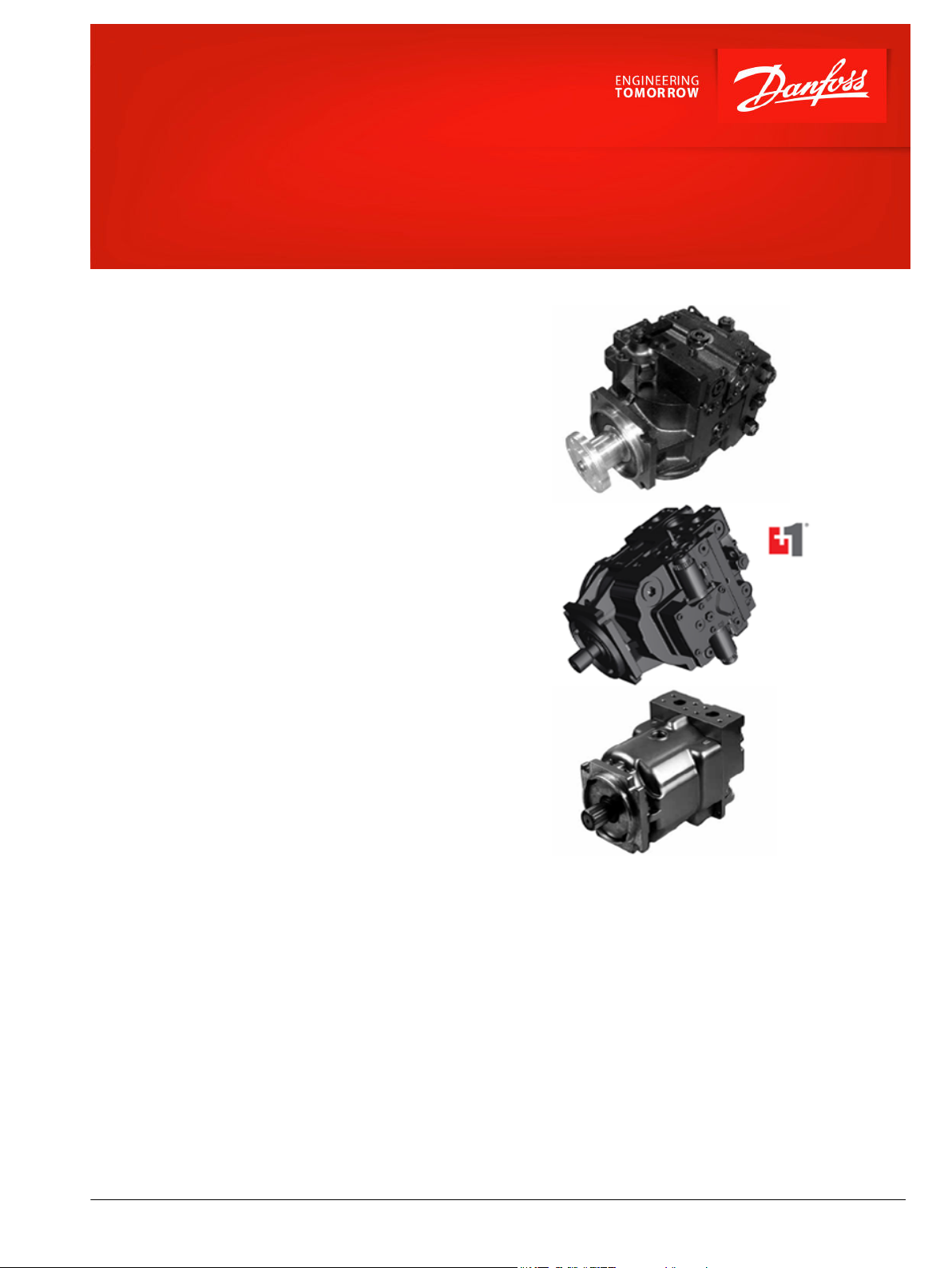
Data Sheet
T90 High Power Closed System
055/075/100 cm³
Danfoss T90 variable pump is on the base of S90
variable pump, combined with Danfoss’s the global
application of experience and the latest technology to
develop a new axial piston variable pump, it can
cooperate T90 motor or other hydraulic products of
hydraulic drive system to achieve the fluid
transmission and control, mainly used in closed
system.
Currently, Danfoss T90 products only for truck mixer
drum drive, but also walk close system of agricultural.
For the two applications, T90 has released different
configuration options for the user to select. please
refer pump type code.
Series T90 variable displacement pumps are compact,
high power density units. All models utilize the
parallel axial piston/slipper concept in conjunction
with a tiltable swashplate to vary the pump’s
displacement. Reversing the angle of the swashplate
re-verses the flow of oil from the pump and thus
reverses the direction of rotation of the motor output.
Series T90 pumps include an integral charge pump
which is manually controlled to pro-vide system
replenishing and cooling oil flow, as well as control
fluid flow.
Series T90 motors also use the parallel axial piston/
slipper design in conjunction with a fixed swashplate.
They can intake/discharge fluid through either port;
they are bidirectional. They also include an optional
loop flushing feature that provides additional cooling
and cleaning of fluid in the working loop.
Features
T90 Variable Displacement Pump
•
Proven reliability and performance
•
Compact, lightweight
•
Metric thread
•
MDC and EDC available
•
PLUS+1TM compliant controls and
sensors
T90 Fixed Displacement Motor
•
Proven reliability and performance
•
Same displacement with pump
•
Metric thread
•
Integral non-adjustable loop flushing
valve is incorporated
©
Danfoss | May 2021 AI152986483170en-000302 | 1
M4
M5
T P
Feedback
from
swashplate
A – 0 – B
Switch
Neutral
Start
P102 035E
0
Lever rotation
A
Displacement
100 %
a
-a
100 %
B
-b
b
P102 034E
-35 max.
35 max.
Feedback from
Swash plate
PTF00B
M14
1C2C
F00A
P003 478E
"0"
Current mA
Displacement
100 %
a b
-b -a
100 %
P102 026E
Data Sheet
T90 High Power Closed System
Technical Specifications
Features Unit
055 075 100
Size
Displacement cm3 [in3] 55 [3.35] 75 [4.59] 100 [6.10]
Input Speed Min.
Rated 3900 3150 3000
min
-1(rpm)
500 500 500
Max. 4250 3350 3200
System Pressure Continue
Min. 420 [6090]
bar [psi]
400 [5800]
Max. 10 [150]
Charge pump inlet pressure Continue
Min.
(Cold start)
Case pressure Continue
Max. 5.0 [75]
bar [in. Hg vac.]
(absolute)
bar [psi]
0.7 [9]
0.2 [24]
3.0 [40]
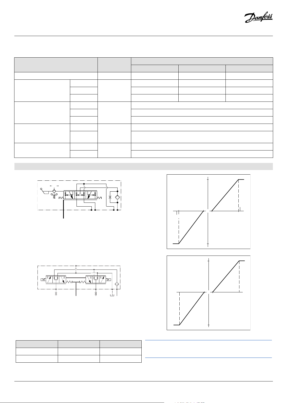
Control
MDC schematic
HCEDC schematic
Option A4 (12V) A5 (24V)
Start (a) 710mA 352mA
Maximum (b) 1640mA 820mA
2 | © Danfoss | May 2021 AI152986483170en-000302
For more product information please contact Danfoss professional sales
staff.
89.9
[3.54]
57.25
[2.254]
43.7
[1.72]
108.7
[4.28]
Approximate
center of
gravity
CCW CW
22.86 Min.
[0.900]
31.3 Max.
95.2
[3.75]
85.2
[3.355]
86.24
[3.395]
57.3
[2.25]
Ø 14.27
[Ø 0.56]
4x
+0.25
-0.13
[+0.01]
[-0.005]
Case drain L2
1-1/16-12UN-2B
Spline data:
Pitch diameter = 33.338 [1.3125]
Pressure Angle = 30°
Number of teeth= 21
Pitch = 16/32
ANSI B92.1-1970, class 5,
fillet root, side fit
P400585
Case drain L2
1-1/16-12UN-2B
Case drain L1
1-1/16-12UN-2B
246.8
[9.72]
57.2
[2.25]
231.8
[9.13]
120.5
[4.74]
287.8
[11.33]
47.6
[1.87]
33.8
[1.33]
12.7
[0.50]
7.9
138.8
[5.46]
M10
[10.000]
134.2
[5.28]
117.6
[4.63]
156.8
[6.17]
Approximate
center of
gravity
Split flange boss
Ports A and B
1.00 - 6000 psi
Per ISO 6162
M12 x 1.75
Minimum full thread 24mm
27.8
[1.09]
Port S :
Charge pump inlet
1-5/16-12UN-2B
Gauge port M2
syetem pressure B
9/16-18UNF-2B
Ø28.7
[1.13]
(0.92)
Ø34.42
[1.36]
Ø 127
[Ø 5]
0
-0.05
[+0.00]
[-0.02]
Ø83 Min.
[Ø3.27]
P400586
2
Spline flange port
Coupling must not protrude beyond
this point
94.2
[3.71]
Ø 94 Min.
[3.7]
94
[3.70]
40.6
[1.60]
4x 57.25
[2.254]
110.7
[4.36]
155.7
[6.13]
Ø37.59
[1.48]
M10
[10.000]
Ø34.16
[1.345]
95.5
[3.76]
91.7
[3.61]
57.25
[2.254]
Ø 14.34±0.18
[Ø 0.565±0.007]
Ø 0.8
Max.
[0.03]
28.5 Max.
4x
Case drain L2
1-1/16-12UN-2B
Case drain L1
1-1/16-12UN-2B
305.14
[12.013]
14.15
[0.557]
20
Min.
[0.787]
7.9
[0.31]
12.45
[12.45]
38.9
[1.53]
57.2
[2.25]
247.7
[247.74]
242.2
[9.54]
155.7
[6.13]
141.7
[5.58]
139.6
[5.50]
129.5
[5.10]
27.8
[1.09]
124.2
[4.89]
1.00 - 6000 psi
Per ISO 6162
bolt M21 x 1.75
Minimum full thread 24mm
Case drain L2
1-1/16-12UN-2B
Ø 127
[Ø 5]
0
-0.05
[+0.00]
[-0.02]
CCW CW
Approximate
center of
gravity
Spline data:
Pitch diameter = 36.513 [1.4375]
Pressure Angle = 30°
Number of teeth= 23
Pitch = 16/32
ANSI B92.1-1970, class 5,
fillet root, side fit
Appr.
center of
gravity
P400587
107.95
[4.25]
57.25
[2.25]42[1.65]
119.6
[4.71]
CCW CW
20 Min.
[0.787]
28.5 Max.
108.8
[4.28]
100.36
[3.95]
101.4
[3.99]
57.25
[2.25]
Ø 14.27
[Ø 0.56]
4x
+0.25
-0.13
[+0.01]
[-0.005]
Case drain L2
1-1/16-12UN-2B
Case drain L2
1-1/16-12UN-2B
280.4
[11.04]
57.15
[2.25]
277.8
[10.93]
160.9
[6.34]
338.3
[13.33]
47.6
[1.87]
38.9
[1.53]
12.4
[0.49]
7.9
164.7
[6.48]
M10
[10.000]
153.7
[6.05]
138.32
[5.45]
180.3
[7.1]
27.8
[1.09]
Ø34.16
[1.345]
(0.8)
Ø37.59
[1.48]
Ø 127
[Ø 5]
0
-0.05
[+0.00]
[-0.02]
Ø101.3 Min.
[Ø3.99]
Gauge port M2
syetem pressure B
9/16-18UNF-2B
Case drain L1
1-1/16-12UN-2B
Port S :
Charge pump inlet
1-5/8-12UN-2B
Approximate
center of
gravity
Split flange boss
Ports A and B
1.00 - 6000 psi
Per ISO 6162
M12 x 1.75
Minimum full thread 24mm
Spline data:
Pitch diameter = 36.513 [1.4375]
Pressure Angle = 30°
Number of teeth= 23
Pitch = 16/32
ANSI B92.1-1970, class 5,
fillet root, side fit
Approximate
center of
gravity
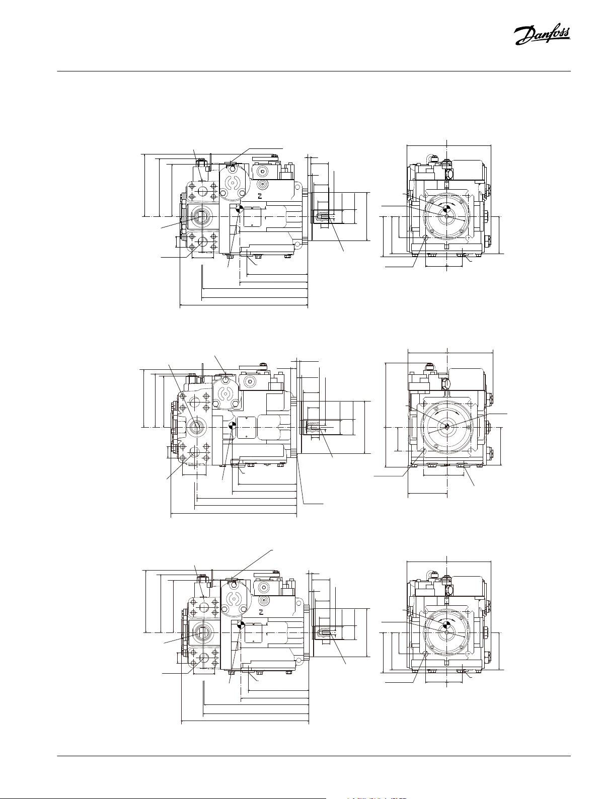
Data Sheet
T90 High Power Closed System
Series T90 Variable Axial Piston Pump : Dimensions (mm)
055 (55 cm3/rev) End cap option: 8A
075 (75 cm3/rev) End cap option: 8A
100 (100 cm3/rev) End cap option: 8A
©
Danfoss | May 2021 AI152986483170en-000302 | 3
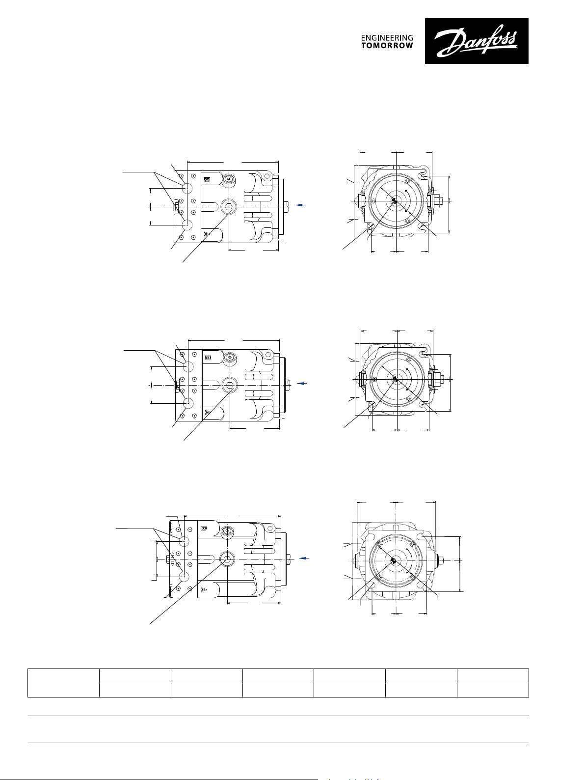
Series T90 Axial Piston Motor : Dimensions (mm)
P400588
82.3
[3.24]
CCW
CW
57.25
[2.254]
73.2
[2.88]
Ø85.5
[Ø3.37]
Min.
57.25
[2.254]
82.3
[3.24]
R 7.4 ± 0.8
[R 0.29 ± 0.031]
(4
x
)
Port
"B"
Port "A
"
73.2
[2.88]
Port "A"
Port "B"
41.78
[1.645]
41.78
[1.645]
189.6
[7.46]
103.5
[4.07]
"X"
"X" View
Split flange boss
Ports A and B
1.00 - 6000 psi
Per ISO 6162
M12 x 1.75
Minimum full thread 24mm
Case drain L2
7/8-14UN-2B
Case drain L2
Case drain L1
Approximate
c
enter of
gravity
P400589
82.6
[3.25]
CCW
CW
57.25
[2.254]
73.2
[2.88]
Ø94
[Ø3.70]
57.25
[2.254]
82.6
[3.25]
R 7.4 ± 0.8
[R 0.29 ± 0.031]
(4x)
73.2
[2.88]
41.78
[1.645]
41.78
[1.645]
208.8
[8.22]
113.8
[4.48]
"X"
Split flange boss
Ports A and B
1.00 - 6000 psi
Per ISO 6162
M12 x 1.75
Minimum full thread 24mm
Case drain L2
1-1/16-12UN-2B
Port "A
"
Port "B"
"X" View
Approximate
c
enter of
gravity
Min.
Case drain L2
Case drain L1
Port
"B"
Port "A
"
P400590
CCW
CW
57.25
[2.254]
73.2
[2.88]
Ø100.6
[Ø3.96]
Min.
73.2
[2.88]
57.25
[2.254]
R 7.4 ± 0.76
[R 0.29 ± 0.03]
(4x)
92.2
[3.63]
95
[3.74]
"X"
41.78
[1.645]
41.78
[1.645]
128
[5.04]
230.9
[9.09]
Split flange boss
Ports A and B
1.00 - 6000 psi
Per ISO 6162
M12 x 1.75
Minimum full thread 24mm
Port "B"
Port "A"
Case drain L2
1-1/16-12UN-2B
Approximate
c
enter of
gravity
Case drain L2
Case drain L1
Port
"B"
Port "A
"
"X" View
055 (55 cm3/rev)
075 (75 cm3/rev)
100 (100 cm3/rev)
Shaft diameter Full spline length Major diameter Pitch diameter Number of teeth Pitch
28.7 [1.13] 32.5 [1.28] 34.42 [1.355] 33.336 [1.3125] 21 16/32
Output shaft parameters
Splined shaft
Danfoss can accept no responsibility for possible errors in catalogues, brochures and other printed material. Danfoss reserves the right to alter its products without notice. This also applies to products
already on order provided that such alterations can be made without subsequent changes being necessary in specifications already agreed.
All trademarks in this material are property of the respective companies. Danfoss and the Danfoss logotype are trademarks of Danfoss A/S. All rights reserved.
4 | © Danfoss | May 2021 AI152986483170en-000302
 Loading...