

Page 1
Installation Instruction
Danfoss Self-limiting Heating Cables
ECpipeguard 10/25/33 (SLPG-10/26/33)
ECiceguard 18 (SLPG-15, SLIG-18)
EChotwatt 45/55/70 (SLHW-45/55/70)
ECpipeheat 10 (SLPH-10)
© Danfoss | FEC | 2019.02
Page 2

Page 3
Installation Instruction Danfoss Self-limiting Heating Cables
Installation Instruction
GB
© Danfoss | FEC | 2019.02 | 3088L8008 / VIAMQ502
Page 4
Installation Instruction Danfoss Self-limiting Heating Cables
Table of Contents
1. Introduction . . . . . . . . . . . . . . . . . . . . . . . . . . . . . . . . . . . . . . 4
2. Installation in General . . . . . . . . . . . . . . . . . . . . . . . . . . . . . . . . . 8
3. Installing Heating Elements . . . . . . . . . . . . . . . . . . . . . . . . . . . . . . 10
4. Application . . . . . . . . . . . . . . . . . . . . . . . . . . . . . . . . . . . . . . . 12
5. Finalizing the Installation . . . . . . . . . . . . . . . . . . . . . . . . . . . . . . . 16
1.1 Self-limiting Heating Cables . . . . . . . . . . . . . . . . . . . . . . . . . . . 5
1.2 Safety Instructions . . . . . . . . . . . . . . . . . . . . . . . . . . . . . . . . 5
1.3 Handling . . . . . . . . . . . . . . . . . . . . . . . . . . . . . . . . . . . . . 6
1.4 System Overview . . . . . . . . . . . . . . . . . . . . . . . . . . . . . . . . . 7
1.5 Functional Overview . . . . . . . . . . . . . . . . . . . . . . . . . . . . . . . 7
2.1 Fastening Methods . . . . . . . . . . . . . . . . . . . . . . . . . . . . . . . . 8
2.2 Calculating C-C Distance . . . . . . . . . . . . . . . . . . . . . . . . . . . . . 8
2.3 Calculating Cable Length . . . . . . . . . . . . . . . . . . . . . . . . . . . . . 9
2.4 Max. Cable Length . . . . . . . . . . . . . . . . . . . . . . . . . . . . . . . . 9
2.5 Planning the Installation . . . . . . . . . . . . . . . . . . . . . . . . . . . . . 10
2.6 Preparing the Installation Area . . . . . . . . . . . . . . . . . . . . . . . . . . 10
3.1 Installing Elements . . . . . . . . . . . . . . . . . . . . . . . . . . . . . . . . 11
4.1 Installation on Pipes . . . . . . . . . . . . . . . . . . . . . . . . . . . . . . . 12
4.2 Installation in pipes . . . . . . . . . . . . . . . . . . . . . . . . . . . . . . . 14
4.3 Installation Inside the Pipe . . . . . . . . . . . . . . . . . . . . . . . . . . . . 15
4.4 Installing on Roof and Gutters . . . . . . . . . . . . . . . . . . . . . . . . . . 15
5.1 Connecting a Thermostat . . . . . . . . . . . . . . . . . . . . . . . . . . . . . 17
1 Introduction
In this installation manual, the word “element” refers
to heating cables.
For other applications please contact your local
sales office.
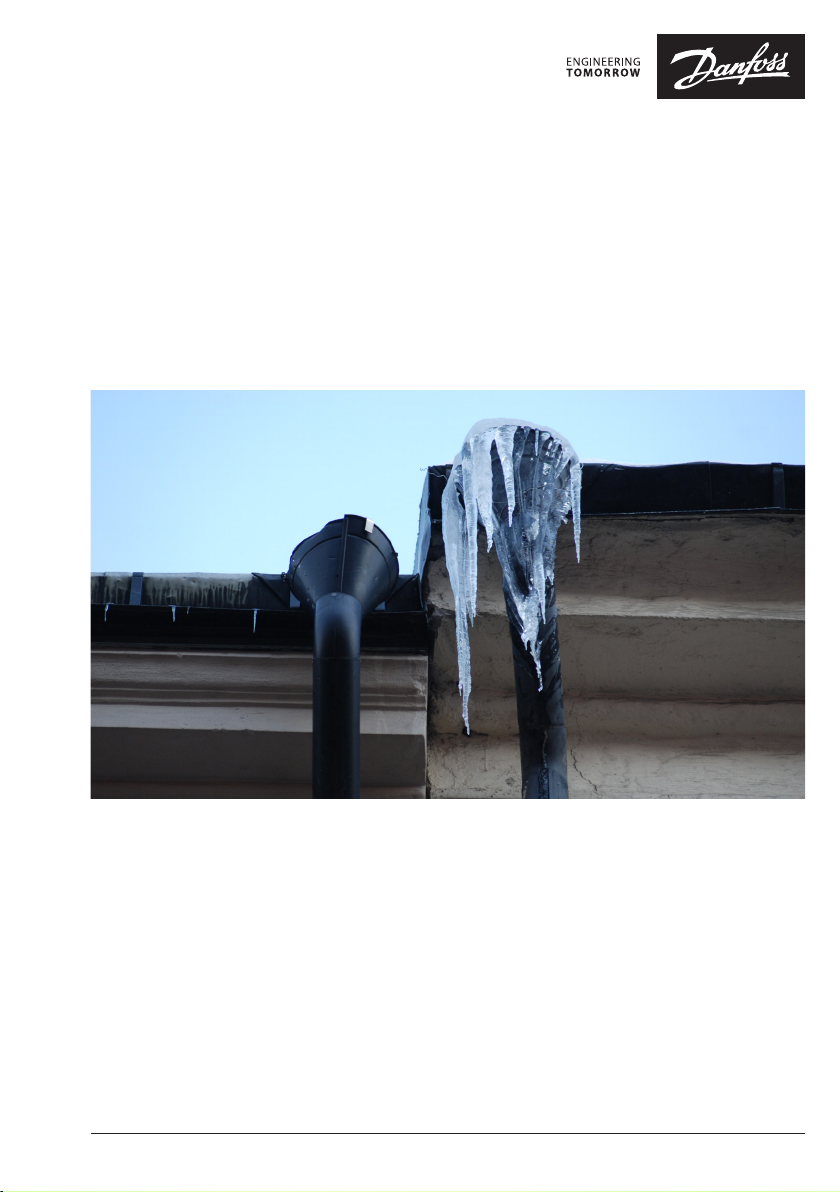
Frost protection of roof and gutter systems
- see section 4.4
Frost protection of pipe systems
- see section 4.1, 4.2, 4.3
088L8008 / VIAMQ5024 | © Danfoss | FEC | 2019.02
Page 5
Installation Instruction Danfoss Self-limiting Heating Cables
1.1 Self-limiting Heating Cables
Introduction
The heating cables are used mainly for ice and snow
melting on roofs and in gutters, down pipes, for
frost protection of pipes and for temperature maintenance of the hot-water supply.
There are 4 types of Danfoss self-limiting heating
cables with various effects depending on the application.
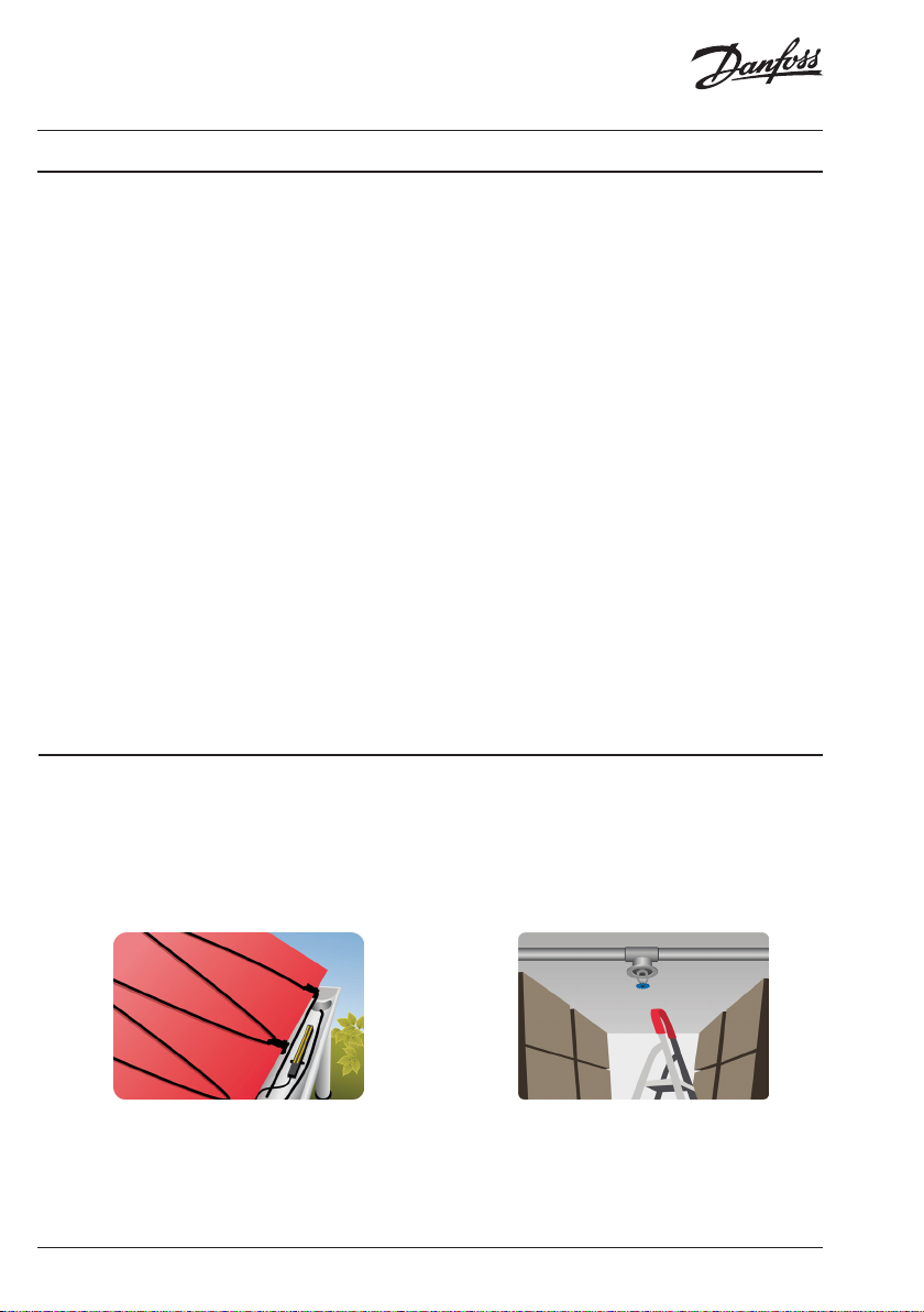
Cable Construction
Self-limiting heating cables are designed with a
temperature dependant resistant element between
two parallel copper bus wires.
When the bus wires are connected to the mains, a
current goes through the temperature dependant
resistant element which will then heat. As the element is heated the resistance value rises causing
the current to decline and heating is reduced. This
explains the self-limiting effect.
1
2
3
5
4
The regulation of the output takes place independently on the entire length of the cable according
to the actual ambient temperature.
If the ambient temperature rises the heating effect
of the cable is reduced. Due to this self-limiting
capability, overheating of the cable can be avoided,
also if two heating cables are touching or crossing.
As self-limiting heating cables always gives off a
certain amount of effect, it is recommended to
connect the heating cable to a thermostat to be
able to disconnect the current when heating is not
required.
Due to the parallel power supply the heating cable
can be shortened anywhere. This simplifies the
planning and installation.
1. Outer sheath
2. Screen
3. Insulation
4. Self-limiting heating element
5. Bus wires
GB
1.2 Safety Instructions
This appliance can be used by children aged from 8
years and above and persons with reduced physical,
sensory or mental capabilities or lack of experience
and knowledge if they have been given supervision
or instruction concerning use of the appliance in a
safe way and understand the hazards involved.
Children shall not play with the appliance. Cleaning
and user maintenance shall not be made by children without supervision.
© Danfoss | FEC | 2019.02 | 5088L8008 / VIAMQ502
Page 6
Installation Instruction Danfoss Self-limiting Heating Cables
Elements must always be connected by an authorised electrician using a fixed connection.
• De-energize all power circuits before installation and service.
• The connection to the power source must not
be directly accessible to the end user.
• Each heating cable screen must be earthed in
accordance with local electricity regulations and
Elements must always be installed according to
local building regulations and wiring rules as
well as the guidelines in this installation manual
• Any other installation may hamper element
functionality or constitute a safety risk, and
will void the warranty.
• Make sure that elements, cold leads, connection boxes, and other electrical components do
not come into contact with chemicals or flammable materials during or after installation.
Pipe Tracing
connected to a residual current device (RCD).
• Recommended RCD trip rating is 30 mA, but
may be up to 300 mA where capacitive leakage may lead to nuisance tripping.
• Heating elements must be connected via a
switch providing all pole disconnection.
• The element must be equipped with a correctly sized fuse or circuit breaker, e.g. 10/13 A
for a 1.5 mm2 cold lead and 16/20 A for a
2.5 mm2 cold lead.
• Sensor
• Heating Cable
• Insulation
• Fitting
• Valve
1.3 Handling
• If the heating cable is delivered on a cable
drum you should use a reliable holder for the
drum when unrolling the cable.
• Pull the heating cable straight of the drum.
The presence of a heating element must
• be made evident by affixing caution signs or
markings at the power connection fittings
and/or frequently along the circuit line where
clearly visible.
• be stated in any electrical documentation
following installation.
Never exceed the maximum heat density (W/m)
for the actual application.
• Avoid pulling violently, breaking or squeezing
the heating cable.
• Do not place the heating cable over sharp
objects or edges.
088L8008 / VIAMQ5026 | © Danfoss | FEC | 2019.02
Page 7

Installation Instruction Danfoss Self-limiting Heating Cables
• The heating cable must be protected against
excess strain and tension. Stepping on the cables or crossing the cables with vehicles should
be avoided, as this may damage the cables.
• The surface onto which the cable is to be in-
• Do not connect power to heating cable while
it is on the drum or shipping carton.
• When storing the cable, the ends must be
sealed to keep out moisture that could otherwise damage the cable.
stalled must be clean and free of sharp objects.
• Never secure the cable with metal or metal
strips.
1.4 System Overview
Cable Color Application Effect @ 230 V Dimension Cap Mechanical Class
ECpipeguard 10 Blue On pipes 10 W/m @ 10° C 5,5 x 11,8 mm TPE IEC 60800:M2
ECpipeguard 25 Red On pipes 25 W/m @ 10° C 5,5 x 11,8 mm TPE IEC 60800:M2
ECpipeguard 33 Brown On pipes 33 W/m @ 10° C 5,5 x 11,8 mm TPE IEC 60800:M2
ECiceguard 18 Black Roof & gutter 18 W/m @ 10° C 5,8 x 11,3 mm TPE, UV IEC 60800:M2
EChotwatt 45 Black On pipes 7 W/m @ 45° C 5,5 x 11,8 mm TPE IEC 60800:M2
EChotwatt 55 Green On pipes 8 W/m @ 55° C 5,8 x 11,8 mm TPE IEC 60800:M2
EChotwatt 70 Red On pipes 12 W/m @ 70° C 5,8 x 11,8 mm TPE IEC 60800:M2
ECpipeheat 10 Blue On / in pipes 10 W/m @ 10° C 5,3 x 7,7 mm TPE IEC 60800:M2
Voltage 220V - 240V AC
Minimum installation temperature -50° C.
Note:
• The stated effect is measured on the cable
installed on pipe under insulation.
• The Self-limiting cables have to be in good
thermal contact with the item to be heated.
Max. temperature ON = 65° C.
Max. temperature OFF = 85° C.
• When self-limiting cables are surrounded
by thermal conducting materials (water /
concrete, etc.) the effect may be double in
relation to the nominal value.
GB
1.5 Functional Overview
1. Element
2. C-C distance
3. Cold lead connection
4. Cold lead
5. Connection box (if any)
6. Sensor
7. Thermostat
© Danfoss | FEC | 2019.02 | 7088L8008 / VIAMQ502
Page 8

Installation Instruction Danfoss Self-limiting Heating Cables
2 Installation in General
2.1 Fastening Methods
Danfoss Aluminium Tape
For ensuring efficient heat transfer.
2.2 Calculating C-C Distance
For areas on roofs the C-C distance is the distance in
centimetres from the centre of one cable to the
centre of the next.
Area [m²]
C-C =
Cable length [m]
Cable output [W/m]
C-C =
Heat density [W/m²]
The max. C-C distance for roof and gutter systems is
10 cm.
C-C [cm] 20 W/m 25 W/m 30 W/m
5 366 457 -
7,5 244 305 366
10 183 229 274
x 100 cm
x 100 cm
W/m² @ 220 V
Spaceclip
For attaching cables and relieving from sharp edges.
W/m² @ 230 V
C-C [cm] 20 W/m 25 W/m 30 W/m
5 400 500 -
7,5 267 333 400
10 200 250 300
W/m² @ 240 V
C-C [cm] 20 W/m 25 W/m 30 W/m
5 436 544 -
7,5 290 363 436
10 218 272 327
ECiceguard 18
C-C [cm] 220 V 230 V 240 V
5 329 W/m² 360 W/m² 392 W/m²
7,5 219 W/m² 240 W/m² 262 W/m²
10 165 W/m² 180 W/m² 196 W/m²
088L8008 / VIAMQ5028 | © Danfoss | FEC | 2019.02
Page 9

Installation Instruction Danfoss Self-limiting Heating Cables
2.3 Calculating Cable Length
Please consider all of the below when calculating
the length of the heating cable:
• Heated pipe length
• Number of connections x 0,3 m heating cable.
• Number of specials x 0,5 m heating cable.
• Number of T-derivations x 1 m heating cable.
• Heating cable length for flanges, fittings and
measured pipe extensions.
2.4 Max. Cable Length
ECiceguard 10 (SLPG-10) ECiceguard 25 (SLPG-26) ECiceguard 33 (SLPG-33)
Max. heating cable length at 230 V
FUSE FUSE FUSE
Temperature 16 A 20 A 25 A 16 A 20 A 25 A 16 A 20 A 25 A
-30 °C 120 m 150 m 170 m 45 m 64 m 82 m 43 m 52 m 65 m
-15 °C 139 m 186 m 190 m 58 m 75 m 95 m 49 m 64 m 80 m
10 °C 205 m 205 m 205 m 88 m 117 m 120 m 70 m 90 m 98 m
ECiceguard 18
(SLIG-18, SLPG-15)
FUSE FUSE FUSE FUSE
Temperature 10 A 16 A 20 A 16 A 20 A 16 A 20 A 16 A 20 A
-30 °C 40 m 77 m 106 m 117 m 152 m 100 m 130 m 88 m 120 m
-15 °C 60 m 93 m 125 m - - - - - -
0 °C 80 m 110 m 135 m - - - - - -
10 °C 105 m 145 m 162 m 165 m 189 m 135 m 160 m 120 m 140 m
EChotwatt 45
(SLHW-45)
Max. heating cable length at 230 V
EChotwatt 55
(SLHW-55)
EChotwatt 70
(SLHW-70)
GB
ECpipeheat 10 (SLPH-10)(on pipe) ECpipeheat 10 (SLPH-10)(in pipe)
Max. heating cable length at 230 V
FUSE FUSE
Temperature 10 A 16 A 10 A 16 A
-20 °C 77 m - - 0 °C 96 m - - -
10 °C 100 m - 60 m -
© Danfoss | FEC | 2019.02 | 9088L8008 / VIAMQ502
Page 10

Installation Instruction Danfoss Self-limiting Heating Cables
2.5 Planning the Installation
Draw a sketch of the installation which shows
• element layout
• cold leads and connections
• junction box/cable well (if applicable)
• sensor
• connection box
• thermostat
Save the sketch
• Knowing the exact location of these components makes subsequent troubleshooting
and repair of faulty elements easier.
Bear in mind the following:
• Observe correct C-C distance (heating cables
only) - see section 2.2.
• Observe required installation depth and possible mechanical protection of cold leads.
• When installing more than one element,
never wire elements in series but route all
cold leads in parallel to the connection box.
2.6 Preparing the Installation Area
• Remove all traces of old installations, if applicable.
• Ensure that the installation surface is even,
stable, smooth, dry and clean.
• If necessary, fill out gaps around pipes,
drains, or walls or apply foil covering
• There must be no sharp edges, leaves, dirt or
foreign objects.
3 Installing Heating Elements
It is not recommended to install elements at temperatures below -5 °C.
At low temperatures, heating cables can become
rigid. After rolling out the element, briefly connect
it to the mains supply to soften the cable before
fastening.
Measuring Resistance
Measure, verify and record element resistance during installation.
• After unpacking
• After fastening the elements
• After the installation in finalized
Also measure if there is connection between the
two conductors or from the conductor to the metal
sheath.
088L8008 / VIAMQ50210 | © Danfoss | FEC | 2019.02
Page 11

Installation Instruction Danfoss Self-limiting Heating Cables
If the insulation resistance is not as labelled, the
element must be replaced.
• Check for short circuits by measuring between the two bus wires and the screen.
3.1 Installing Elements
The heating cables bending diameter must not be
less than 25 mm (32 mm for SLPG-18). The cable
must only be bended on the flat side.
For reduction of electricity consumption, we strongly recommend that it is possible to switch off the
heating cable, i.e. by using a ECtemp thermostat.
After installation the cable insulation resistance
must be measured and recorded.
At low temperatures the heating cable can become
stiff and difficult to work with. This problem can
be solved by connecting the unreeled cable to the
mains for a brief period of time.
GB
© Danfoss | FEC | 2019.02 | 11088L8008 / VIAMQ502
Page 12

Installation Instruction Danfoss Self-limiting Heating Cables
4 Application
4.1 Installation on Pipes
Frost protection of pipe systems [W/m]
Δt [K] Insulation [mm]
10 8 9 11 14 16 19 24 29 36 44 - -
20 5 6 7 8 9 11 14 16 19 24 28 36
20
30
40
30 4 5 5 6 7 8 10 12 14 17 19 25
40 4 4 5 5 6 7 8 9 11 13 15 19
50 3 4 4 5 5 6 7 8 9 11 13 16
10 12 14 17 20 24 29 37 44 - - - -
20 8 9 10 12 14 17 20 24 29 35 42 -
30 6 7 8 9 11 12 15 18 21 25 29 37
40 5 6 7 8 9 10 12 14 17 20 23 29
50 5 6 6 7 8 9 11 12 14 17 19 24
10 15 19 22 27 32 39 49 - - - - -
20 10 12 14 16 19 22 27 32 39 47 - -
30 8 9 11 12 14 17 20 23 28 33 39 50
40 7 8 9 10 12 14 16 19 22 26 31 39
50 6 7 8 9 10 12 14 16 19 22 26 32
15 20 25 32 40 50 65 80 100 125 150 200
Pipe diameter DN [mm]
Pipe tracing
• Sensor.
• Heating cable.
• Insulation.
• Fitting.
• Valve.
088L8008 / VIAMQ50212 | © Danfoss | FEC | 2019.02
Page 13

Installation Instruction Danfoss Self-limiting Heating Cables
There must always be as much insulation as possible on the pipe to reduce the heat loss.
The self-limiting heating cable may only be used for
installations with pipes of metal or plastic.
When installing heating cables on plastic pipes:
• Place a strip of aluminium tape on the pipe.
• Place the heating cable on the aluminium
tape.
• Secure the heating cables with aluminum
tape.
It is recommended that the entire cable is covered
with aluminum tape, to ensure efficient heat transfer to the plastic pipe.
The cable must be placed optimal on the 5 or 7
o’clock position of the pipe, thus mechanical strain
of the heating cable is prevented when e.g. the
insulators are working along the pipe.
WARNING!
230V AC HEATING CABLE
• When the heating cable is installed on pipes,
the insulation should be clearly marked with
a warning.
Installation on Special Flanges and Pumps
• Always observe the minimum tolerable bending diameter of 50 mm (64 mm for ECiceguard 18 (SLPG-15, SLIG-18)!
• Heating cables on specials, valves etc. should
always be positioned so that they are easily
assessable and replaceable in connection
with inspection and repair and so that it will
not be necessary to cut them! You can avoid
this problem when there is sufficient cable
wrapped in a spiral around the specials.
GB
© Danfoss | FEC | 2019.02 | 13088L8008 / VIAMQ502
Page 14

Installation Instruction Danfoss Self-limiting Heating Cables
1. Valve
2. Heating cable
3. Aluminium tape
4. Pipe
5. Pipe fitting
Installation Summary
Straight cables must be fitted as shown at 5 or 7
o’clock. Inpipe cables are fitted directly in the pipe with
compression gland. Cables wrapped around pipes are
attached as shown for every 20-30 cm of pipe with
aluminium tape (for large pipe diameters only).
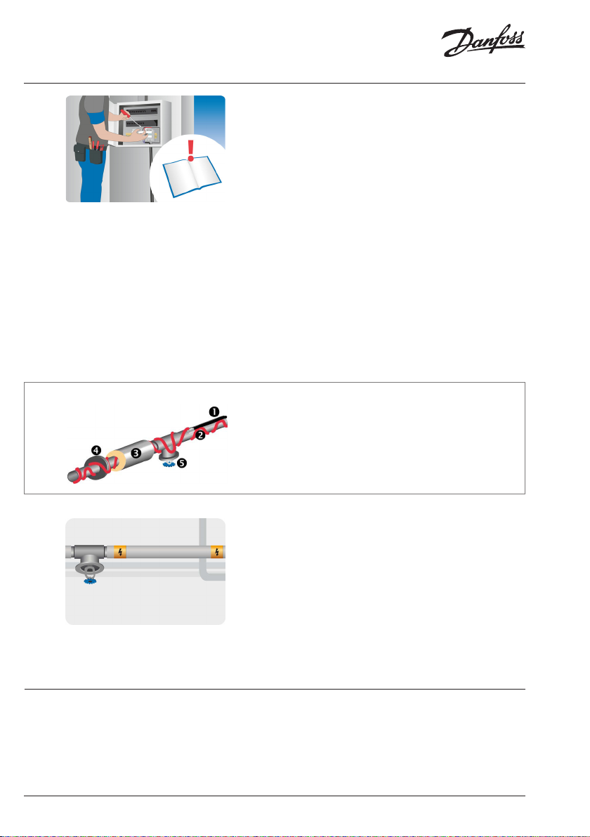
4.2 Installation in pipes
In-pipe Frost Protection
Extend cold leads/terminate cables, and place connections in a dry place. Mount connection box on or
close to pipe, and install thermostat next to pipe.
1. Insulation.
2. Heating cable.
3. Sensor (optional - not shown).
4. Fitting.
088L8008 / VIAMQ50214 | © Danfoss | FEC | 2019.02
Page 15

Installation Instruction Danfoss Self-limiting Heating Cables
• Installation of ECpipeheat 10 (SLPH-10) in
pipes is energy-saving, because the heating
cable is in direct contact with the fluid that is
to be heated.
• Do not use the heating cable in pipes with
inletwater pressure above 1 MPa (10 bar).
Please note that in this case the heating cable
must be connected via a fault current relay
(RCD), and it must be possible to disconnect
the heating cable.
• Never install the heating cable in taps and
valves.
4.3 Installation Inside the Pipe
1. Fit a T-shaped pipe of a generous size over the
pipe.
2. Fit the wadding (the item with male thread)
inside the T-shaped pipe.
3.
Push the heating cable through the wadding,
using lubricant to facilitate the installation. The
connection between heating cable and connecting cable must be outside the wadding.
4. Mount the Wadding in the following sequence:
• Mount the nut with the flat side facing
the connection.
• Mount the washer on the heating cable.
• Squeeze the rubber seal on the heating
cable.
• Never switch on power, before the pipe is filled.
• If the heating cable is damaged during installation, it must be replaced.
• When the heating cable is installed in pipes,
the pipe or insulation should be clearly
marked with a warning.
WARNING!
230V AC HEATING CABLE
5. Mount the male threaded part with the female
threaded part facing the end of the cable.
6. The heating cable must extended straight
through the T-shaped pipe.
7. Turn the wadding until it fits tightly
8. Insulate the pipe with at least 30 mm insulation or more if required.
GB
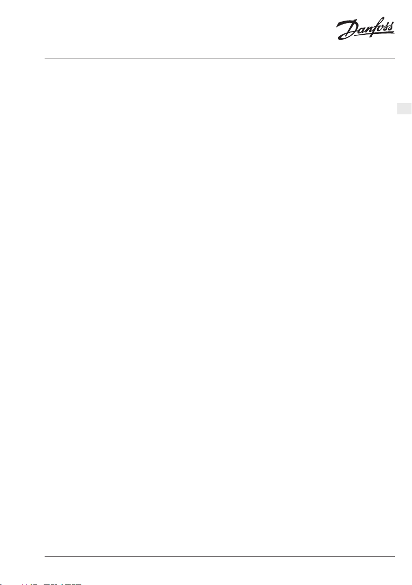
4.4 Installing on Roof and Gutters
To provide sufficient heat in gutters, the heat density and the number of cable lines, depends on the
design temperature and the gutter diameter.
1. Roof edge / eave
2. Gutter
3. Downpipe to frost-free well
4. Gutter valley
5. Flat roof with drain
6. Roof with baffles
7. Downpipe with open end
© Danfoss | FEC | 2019.02 | 15088L8008 / VIAMQ502
Page 16

Installation Instruction Danfoss Self-limiting Heating Cables
Design temperature Heat density Cable lines C-C
°C [W/m²] [No.] [cm]
0 to -5 200 - 250 1 8-9
-6 to -15 250 - 300 2 7
-16 to -25 300 - 350 2 6
-26 to -35 350 - 400 3 4-5
We recommend that you always use a controller for controlling the self-limiting heating cables to avoid
waste of energy.
Inform the end user to check for and remove sharp
edges, leaves, and dirt from the heated roof and
gutter systems every autumn.
5 Finalizing the Installation
Connecting cables
• Connect all cold leads and the sensor to the
connection box.
• See the installation manual for the thermostat.
Final check and documentation
• Make sure that the heat distributor (e.g.
roof, pipe) can withstand the heat from the
element. This is particularly important if the
element is connected to a thermostat that
does not allow configuration of maximum
temperature - see section 4.4.
• Document the following using text, drawings,
or photos:
• cable type, spacing, depth, layout,
circuit ID, sensors.
• location of connections between cold
lead and heating element.
• location of end caps (twin conductors
only).
• location of expansion joints, if any.
• Re-check and compare the insulation resistance.
088L8008 / VIAMQ50216 | © Danfoss | FEC | 2019.02
Page 17

Installation Instruction Danfoss Self-limiting Heating Cables
Hand-over to the end user
• Instruct the end-user or the daily supervisor
in the operation and maintenance of the
heating system.
• Before every period of continuous use, check
for faults in the distribution board, thermostat, and sensors.
5.1 Connecting a Thermostat
GB
If the element is connected to a thermostat such
as a ECtemp, configure basic settings according to
the table below and as described in the thermostat
installation manual.
Thermostat Max. load
Frost protection of roof and
gutter systems
ECtemp 316 16 A -7 °C < On < +3 °C -
ECtemp 330/610 16/10 A On < +3 °C On < +5 °C
ECtemp 850 2 x 15A Melting < +3°C & moisture -
If applicable, adjust the temperature limit in accordance with the manufacturer’s recommendations
in order to prevent damage to e.g. the floor or the
pipe.
• Note, however, that the limit must not exceed
the maximum temperature limit specified per
application (see section 4).
Frost protection of pipe
systems
© Danfoss | FEC | 2019.02 | 17088L8008 / VIAMQ502
Page 18

Installation Instruction Danfoss Self-limiting Heating Cables
Warranty
A 20-year full service warranty is valid for:
• heating cables incl. ECflex, ECsafe, ECsnow,
ECasphalt, ECaqua, ECbasic, ECmulti, ECsport
(DSM3), ECfreeze;
• heating mats incl. ECsnow, ECasphalt, ECflex,
ECsafe.
Not only does this warranty include costs of reparation or replacement, but also installation and floor
materials, such as damage to brickwork and tiles.
A 10-year product warranty is valid for:
• Danfoss Reflect, ECcell insulation plates.
A 5-year product warranty is valid for:
• self-limiting cables incl. ECiceguard,
ECpipeheat, ECpipeguard, EChotwatt.
Should you, against all expectations, experience a
problem with your Danfoss product, you will find
that Danfoss offers Danfoss warranty from the date
of purchase on the following conditions: During
the warranty period Danfoss shall offer a new
comparable product or repair the product in case
the product is found to be faulty by reason of defective design, materials or workmanship. The repair
or replacement shall be carried out free of charge
providing that the warranty claim is valid.
The decision to either repair or replace will be solely
at the discretion of Danfoss. Danfoss shall not be
The Danfoss warranty is granted to:
liable for any consequential or incidental damages
including, but not limited to, damages to property
or extra utility expenses. An extension of the warranty period following repairs undertaken cannot
be granted. The warranty shall be valid only if the
WARRANTY CERTIFICATE is completed correctly and
in accordance with the instructions, and provided
the fault is submitted to the installer or the seller
without undue delay and proof of purchase is provided. Please note that the WARRANTY CERTIFICATE
must be completed in English or local language.
Danfoss warranty shall not cover any damage
caused by incorrect conditions of use, incorrect
installation or if installation has been carried out
by non-authorized electricians. All work will be
invoiced in full if Danfoss is required to inspect or
repair faults that have arisen as a result of any of the
above. The Danfoss warranty shall not extend to
products which have not been paid in full. Danfoss
will, at all times, provide a rapid and effective
response to all complaints and inquiries from our
customers.
The warranty explicitly excludes all claims exceeding the above conditions.
For full warranty text visit www.danfoss.com,
www.danfoss.com/en/warranty/
Address Stamp
Product Art. No.
Laying out Date
& Signature Insulation [MΩ]
Connection Date
& Signature Insulation [MΩ]
088L8008 / VIAMQ50218 | © Danfoss | FEC | 2019.02
Page 19

Installation Instruction Danfoss Self-limiting Heating Cables
GB
© Danfoss | FEC | 2019.02 | 19088L8008 / VIAMQ502
Page 20

Installation Instruction Danfoss Self-limiting Heating Cables
088L8008 / VIAMQ50220 | © Danfoss | FEC | 2019.02
 Loading...