

Page 1

Montage- und Betriebsanleitung / Mounting and Installation Guide
Edelstahl Verteilersysteme / Stainless Steel Distribution Systems SGM,
SGCM, SGTZM, SGTZCM, E-SGTZCM
Danfoss vorgefertigte Edelstahl Verteilersysteme für Fussbodenheizung / Danfoss prefabricated solutions for floor heating
Multifamily
Verteilersysteme
mit Messstation /
distribution systems
with metering unit
Page 2

Montageanleitung / Installation Guide Verteilersysteme / distribution units - Multifamily
SGM
145H0527, 7 heating circuits
145H0527, 7 Heizkreise
SGTZCM E-SGTZCM
SGCM
145H0547, 7 heating circuits
145H0547, 7 Heizkreise
SGTZM
145H0567, 7 heating circuits
145H0567, 7 Heizkreise
145H0587, 7 heating circuits
145H0587, 7 Heizkreise
145H0607, 7 heating circuits
145H0607, 7 Heizkreise
1. INHALT / CONTENT
1.0 Inhalt / Content ........................................................................................................................................................................................................................2
2.0 Anschluss, Sicherheit, Handhabung / Connection, Safety, Handling ...................................................................................................................3
3.0 Installationsanleitung generell / Installation instructions, general .......................................................................................................................5
4.0 Produktvorstellung / Product introduction ...................................................................................................................................................................6
5.0 Schaltpläne / Diagrams ..................................................................................................................................................................................................... 11
6.0 Maßskizze & Anschluss / Dimensional sketch & Connection................................................................................................................................ 12
7.0 Hauptkomponenten / Main components ................................................................................................................................................................... 13
8.0 Montage / Mounting ........................................................................................................................................................................................................... 15
9.0 Montage im Einbauschrank / Mounting in recess box ........................................................................................................................................... 16
10.0 Einstellung und Inbetriebnahme / Adjustment and commissioning ................................................................................................................ 18
11.0 Regeltechnik - Fussbodenheizung / Control - Floor heating ................................................................................................................................23
12.0 Umwälzpumpe / Circulation pump ............................................................................................................................................................................... 29
13.0 Wartung / Maintenance ..................................................................................................................................................................................................... 30
14.0 EU Gutachten / EU Declaration of Conformity ........................................................................................................................................................... 31
15.0 Inbetriebnahmezertifikat / Commissioning Certificate .......................................................................................................................................... 32
2 | © Danfoss | Produced by Danfoss Redan A/S | 2017.05
VI.LZ.P1.5B
Page 3

Montageanleitung / Installation Guide Verteilersysteme / distribution units - Multifamily
2. ANSCHLUSS, SICHERHEIT, HANDHABUNG / CONNECTION, SAFETY HANDLING
GERMAN - DE
Anleitung
Bitte lesen Sie diese Anleitung vor der Installation und Inbetriebnahme des Verteilersystems sorgfältig durch. Der Hersteller übernimmt keine Haftung für Ausfälle oder Schäden, die durch das
Nichtbeachten der Hinweise in dieser Betriebsanleitung entstehen.
Lesen und befolgen Sie sämtliche Anweisungen, um Verletzungen
und/oder Sachschäden zu vermeiden. Das Überschreiten der empfohlenen Betriebsparameter erhöht beträchtlich das Risiko für Verletzungen und/oder Sachschäden.
Die Einbau-, Inbetriebnahme- und Wartungsarbeiten müssen von
(für Heizungs- und Anschlussarbeiten) qualifiziertem und autorisiertem Personal durchgeführt werden.
Sobald die Station eingebaut ist und sich in Betrieb befindet, besteht in der Regel keine Notwendigkeit, die Einstellungen oder andere
Funktionen zu verändern. Das Verteilersystem ist sehr betriebssicher und einfach zu bedienen.
Energiequelle
Das Verteilersystem mit Mess-Station ist in erster Linie für den
Anschluss an eine Fernwärmequelle ausgelegt. Alternative Energiequellen können verwendet werden, wenn die Betriebsbedingungen zu jeder Zeit derjenigen der Fernwärme entsprechen.
Anwendung
Die Danfoss Edelstahl Verteilersysteme für Mehrfamiliehäuser sind
vorgefertigte Heizkreisverteiler für Fußbodenheizung mit
eingebautem Messstation.
Die Verteilsysteme dienen zur Verteilung der Fußbodenheizung
und die Messstationen dienen zur Messung des Heizungsverbrauchs,
typischerweise für jede einzelne Wohnung in einem Wohnblock.
Werkstoffauswahl
Verwenden Sie nur Werkstoffe, die den lokalen Vorschriften entsprechen.
Korrosion
Der maximale Chlorgehalt des Mediums darf nicht mehr als 300
mg/l betragen. Wenn der empfohlene Chlorgehalt überschritten
wird, steigt das Korrosionsrisiko beträchtlich.
Lagerung und Handhabung
Vor dem Einbau muss/müssen die Verteilersystem(e) in einem trockenen und beheizten (d. h. frostfreien) Raum gelagert werden.
(Relative Luftfeuchtigkeit max. 80 % und Lagertemperatur 5–70 °C).
Die Verteilersysteme dürfen nicht höher als im Werk gestapelt
werden. Verteilersysteme, die in Kartons geliefert werden, müssen
an den Handgriffen der Verpackung angehoben werden. Zum Transportieren/Befördern über große Entfernungen müssen die Verteilersysteme auf Paletten platziert werden.
Heben Sie die Verteilersysteme nach Möglichkeit nicht an den Rohren
an, da dadurch Leckagen entstehen können.
ZIEHEN Sie die Anschlüsse nach dem Transport erneut FEST.
Anschluss
Eine Unterbrechung der gesamten Energieversorung zu der Station
muss jederzeit möglich sein, (hierunter auch Stromzufuhr).
Potentialausgleich / Erdung
Unter Potentialausgleich versteht man alle Maßnahmen zum Beseitigenelektrischer Potentialunterschiede (Kontaktspannungen),
die zwischen z.B zwei Rohrleitungen auftreten können. Der Potentialausgleich ist eine wichtige Maßnahme zum Schutz gegen elektrischen Schlag. Potentialausgleich reduziert Korrosion im Wärmetauscher, Durchlauferhitzer, Stationen und Sanitärinstallationen.
Potentialausgleich sollte nach den Bestimmungen 60364-4-41:
2007 und IEC 60364-5-54: 2011 erfolgen.
Bindungsstelle ist mit einem Erdungssymbol auf der rechten unteren Ecke der Montageplatte markiert und es gibt ein Loch in der
Montageplatte und ein Etikett mit Erdungssymbol.
Warnung! Heiße Oberflächen
Einige Teile des Verteilersystems können sehr heiß werden und Verbrennungen verursachen. Seien Sie sehr vorsichtig, wenn Sie sich in
der direkten Umgebung der Station befinden.
Notfälle
Im Falle von Feuer, Leckagen oder sonstigen Gefahren, sind, wenn
möglich, alle Energieversorgungsanschlüsse des Verteilersystems
zu schließen. Zudem ist Abhilfe durch professionelle Fachkräfte zu
schaffen.
Warnung vor Transportschäden
Beim Erhalt und vor dem Einbau ist das Verteilersystem auf eventuelle
Transportschäden zu prüfen. Das Verteilersystem ist mit größter Vorsicht und Sorgfalt zu bewegen und zu bedienen.
Hinweis – Festziehen der Anschlüsse
Vor dem Befüllen der Station mit Wasser sind ALLE Rohrleitungsanschlüsse festzuziehen, da sie von Vibrationen während des Transports
möglicherweise gelockert wurden und Leckagen entstanden sind.
Sobald die Station befüllt wurde und warm ist, sind ALLE Rohrleitungsanschlüsse erneut festzuziehen.
ZIEHEN SIE DIE ROHRLEITUNGSANSCHLÜSSE NICHT ZU FEST AN.
Handhabung
Wir empfehlen, beim Handhaben und Einbauen der Station
geeignetes und sicheres Schuhwerk zu tragen.
Entsorgung
Die Verteilersysteme bestehen aus Materialien, die nicht zusammen
mit dem Hausmüll entsorgt werden dürfen. Die gesammte Energieversorgung unterbrechen und bitte zerlegen Sie das Produkt zur
VI.LZ.P1.5B
Bitte bemerken:
Eingriffe und Nacharbeiten an unseren Komponenten führen zum
Verlust der Gewährleistung.
© Danfoss | Produced by Danfoss Redan A/S | 2017.05 | 3
Page 4

Montageanleitung / Installation Guide Verteilersysteme / distribution units - Multifamily
2. ANSCHLUSS, SICHERHEIT, HANDHABUNG / CONNECTION, SAFETY, HANDLING
ENGLISH - GB
Instructions
Please read these instructions carefully before installing and commissioning this unit. The manufacturer accepts no liability for loss or
damage resulting from failure to comply with these instructions for use.
Read and follow these instructions carefully to prevent the risk of physical injury and/or damage to property. Exceeding the recommended
operating parameters appreciably increases the risk of personal injury
and/or damage to property.
Installation, commissioning and maintenance must be carried out
by qualified and authorised personnel (both plumbing and electrical
work).
Once the system has been installed and is operating, there is normally
no need to alter the settings or other functions. The distribution system
unit is very reliable and easy to operate.
Heat source
The distribution system is primarily designed for connection to district
heating. Alternative energy sources can be used if the operating conditions are equivalent to district heating at all times.
Application
The Danfoss stainless stee l distribution systems for multi family houses
are prefabricated distribution units with incoorporated metering
station. The distribution systems ser ve to distribute floor heating and
the metering stations serve to measure the heating consumption,
typically for each single apartment in an apartment block.
Choise of materials
Only use materials that comply with local regulations.
Potential equalization/grounding
Potential equalization is an electrical equalizer connection to secure
against user contact with dangerous voltage, which may occur for
example between two piping systems. Potential equalization reduces corrosion in heat exchangers, water heaters, district heating
units and plumbing installations.
Potential bonding should be carried out according to 60364-4-41:
2007 and IEC 60364-5-54: 2011.
Bonding poing is marked on the mounting plate below right corner
with an earthing symbol and there will be a hole in the station
mounting plate and a label with earth symbol.
Warning! Hot surfaces
Parts of the unit may be very hot and can cause burn injuries.
Be very careful when you are in the immediate vicinity of the unit
Emergencies
In the event of fire, leaks or other hazards, immediately shut off all
sources of energy to the unit, if possible, and call for appropriate
assistance.
If the domestic hot water is discoloured or malodorous, shut off
all ball valves on the unit notify all users and call for professional
assistance without delay.
Warning about damage during transport
On reception of the unit, and before installing it, check for any evidence of damage during transport.
The unit must be handled and moved with the greatest care and
attention.
Corrosion
The maximum chlorine content of the medium must not be higher
than 300 mg/l. The risk of corrosion increases considerably if the recommended chlorine content is exceeded.
Storage
Before installation, the unit(s) must be stored in a dry, heated (i.e.
frostfree) room.
(Relative humidity max. 80% and storage temp. 5–70°C).
The units must not be stacked higher than the limit at the factory. Units
supplied in cardboard packaging must be lifted using the handles
incorporated in the packaging. Units must be placed on pallets for
transport/moving across large distances.
As far as possible, do not lift the unit by the pipes.
Retighten ALL pipe connections after transport/moving.
Disposal
Dispose of the packaging in accordance with the local regulations for
disposal of used packaging materials. The unit is made of materials
that cannot be disposed of together with household waste.
Close all energy sources and disconnect all connection pipes. Disconnect and dismantle the product for disposal in accordance with the applicable local regulations for the disposal of the individual components.
Connection
It must be possible to cut off all energy sources to the system – including electrical connections – at all times.
NB! - Tightening of connections
Before filling the unit with water, ALL pipe connections MUST be
retightened, as vibrations during transport may have caused leaks.
Once the unit has been filled and the system is hot, ALL pipe connections MUST be retightened once more. DO NOT OVERTIGHTEN THE
PIPE CONNECTIONS.
Handling
We recommend that you wear suitable safety footwear while
handling and installing the unit.
NOTE:
Interventions/rework on our components results in loss of
warranty.
4 | © Danfoss | Produced by Danfoss Redan A/S | 2017.05
VI.LZ.P1.5B
Page 5

Montageanleitung / Installation Guide Verteilersysteme / distribution units - Multifamily
3. INSTALLATIONSANLEITUNG GENERELL / INSTALLATION INSTRUCTIONS, GENERAL
GERMAN - DE ENGLISH - GB
Generell
Die Einbau-, Anschluss- und Wartungsarbeiten bei dem System dürfen nur von qualifiziertem und autorisiertem Personal durchgeführt
werden. Der Einbau muss immer gemäß den geltenden Vorschriften
und in Übereinstimmung mit dieser Anleitung erfolgen.
Das System muss so eingebaut werden, dass sie frei zugänglich ist
und ohne unnötige Unterbrechungen gewartet werden kann. Heben Sie das System an der Montage-/Rückplatte an. Befestigen Sie
ihn dann an einer stabilen Wand oder in den Einbauschrank, indem
Sie robuste Bolzen, Schrauben oder Spannbolzen in die vier Bohrlöchern in der Montage-/Rückplatte einsetzen und diese festziehen.
Spülen Sie vor der Inbetriebnahme die Hausverrohrung gründlich
durch, um Verunreinigungen zu entfernen. Prüfen und Reinigen Sie
auch die Schmutzfänger in der Station.
Prüfung und Anschlüsse
Ziehen Sie vor dem Befüllen des Systems mit Wasser erneut alle
Rohrleitungsanschlüsse fest, da sie von Vibrationen und Erschütterungen während des Transports möglicherweise gelockert wurden und Leckagen entstanden sind. Ziehen Sie, sobald das System
mit Wasser gefüllt wurde, die Rohrleitungsanschlüsse erneut fest,
bevor Druckprüfungen zur Erkennung von Leckagen durchgeführt
werden. Prüfen Sie nach der Erwärmung des Systems alle Anschlüsse
und ziehen Sie sie, sofern erforderlich, erneut fest.
Bitte beachten Sie, dass die Anschlüsse EPDM-Dichtungen aufweisen können.
Überwurfmuttern NICHT ZU FEST
Überwurfmuttern können zu Leckagen führen.
zu fest angezogene Überwurfmuttern oder durch das Versäumnis
schlüsse erneut festzuziehen, entstanden sind, fallen nicht unter die
Gewährleistung.
Aus diesem Grund ist es wichtig, dass Sie die
ANZIEHEN. Zu fest angezogene
Leckagen, die durch
, An-
General
The installation, connection and maintenance of the system must be
performed by qualified and authorised personnel. Installation must
always be performed in accordance with the applicable legislation
and in compliance with these instructions.
The system must be installed so that it is freely accessible and can be
maintained without unnecessary disruption. Lift the unit by its
mounting plate/rear section (to maximum extent do not lift the
unit by the pipes) and secure it to a solid wall or in the recess box
using expansion bolts or the like positioned in the two bore holes in
the mounting plate. It is recommended that at least two people are
involved in the installation.
Before commissioning, rinse all the pipes in the household piping
system thoroughly to remove any impurities, and check and clean
the dirt strainers in the unit.
Test and connections
Before filling the system with water, retighten all the pipe connections
because vibrations and shocks during transport and handling may
have caused leaks. Once the system has been filled with water, tighten
all the pipe connections once more before performing pressure test
for leaks. After heating of the system, check all the connections and
retighten if necessary.
Please note that the connections may feature EPDM rubber gaskets!
Therefore, it is important that you DO NOT OVERTIGHTEN the union
nuts. Overtightening may result in leaks.
Leaks caused by overtightening or failure to retighten connections
are not covered by the warranty.
VI.LZ.P1.5B
© Danfoss | Produced by Danfoss Redan A/S | 2017.05 | 5
Page 6

Montageanleitung / Installation Guide Verteilersysteme / distribution units - Multifamily
4. PRODUKTINTVORSTELLUNG / PRODUCT INTRODUKTION
GERMAN - DE ENGLISH - GB
Die Danfoss Edelstahl Verteilersysteme für Mehrfamiliehäuser sind
vorgefertigte Heizkreisverteiler für Fußbodenheizung mit
eingebauten Mengen- und Differenzdruckregler und Messstrecke
für den Einbau eines Wärmenmengenzählers.
Die Verteilsysteme dienen zur Versorgung der Fußbodenheizung
und die Messstationen dienen zur Erfassung des Heizungsverbrauchs,
typischerweise für jede einzelne Wohnung in einem Wohnblock.
Die Systeme sind eine ideale Lösung für die Versorgung von Heizung
in Wohnanlagen. Mit einer kleinen Station in jeder Wohnung wird
individuelle Abrechnung je Wohnung möglich.
Das Konzept ist energieträger-unabhängig, - d.h. realisierbar mit
sowohl Gas- oder Ölkessel, Nah- oder Fernwärme sowie
Wärmepumpen und Biomassekessel.
Die Systeme sind als Standardlösungen von 2 bis 12 Heizkreise
erhältlich und beinhalten alle einem Endstück mit manueller
Entlüftung und Entleerung.
Außerdem enthalten die Vorlaufverteiler eine Möglichkeit zur
Einstellung des Volumenstroms der einzelnen Heizkreise am
Durchflussmesser.
Weiterhin beeinhalten alle Systeme einem AB-PM Strangdifferenzdruckregler mit Durchflussbegrenzung und integriertem Regelventil,
SS-FH Manifold, Sicherheitsthermostat STW 55°C, TWA,
Entlüftungsventile und Schmutzfänger im Vorlauf und Rücklauf.
Die Lösungen SGCM, SGTZCM und E-SGTCCZM sind mit einem fest
verdrahtetem Heizkreisregler Masterregler FH-WC 230V und ThermoMotoren TWA-A NC gemäß Anzahl der Heizkreise versehen.
Dadurch wird Anschluss an Raumthermostate ermöglicht, - für
Einzelraumregelung.
Die Lösungen SGTZM, SGTZCM und E-SGTZCM sind mit Anschluß
für Hochtemperaturkreis in Fernwärme Vor- und Rücklauf versehen,
und ermöglicht damit Anschluss eines Handtuchheizkörpers.
Die Lösungen SGTZM und SGT ZCM ist zusätzlich mit hermostatischem
Mischkreis und E-SGTZCM mit elektronischem Mischkreis
ausgestattet.
Die Systeme können in Unterputzausführung mit Einbauschrank
oder in Aufputzausführung montiert werden.
Einbauschränke für Unterputzausführung sind in zwei Größen
erhältlich - H910/B690/T150 mm und H910/B850/T150 mm, - Die
Breite 690 mm passt zu Verteilersystemen mit bis zu 8 Heizkreisen.
Die Breite 850 mm passt zu Verteilersystemen mit bis zu 12
Heizkreisen.
The Danfoss stainless steel distribution systems for multi-family
houses are prefabricated distribution units for floor heating with
built-in volume and differential pressure controllers and measuring
section for energy measurement.
The distribution systems serve to distribute floor heating and the
metering stations serve to measure the heating consumption,
typically for each single apartment in an apartment block.
The system is the ideal solution for the supply of heating in apartment
blocks with a small station in each apartment, as it enables individual
energy billing for each apartment.
The system is independent of the energy source, - i.e. applicable
either with gas boiler or oil boiler, central or district heating as well
as heat pumps and biomass boilers.
The systems are available as standard solutions with 2 to 12
connections and include manual air vent and drain valve.
In addition the solutions include a flow meter to maintain the
designated flow rate.
The systems further more include an AB-PM combined automatic
balancing valve with flow limiter and integrated control valve, SS-FH
manifold, safety thermostat STW 55°C, TWA, air vents and strainer
in supply and return.
The solutions SGCM, SGTZCM and E-SGTCCZM are fitted with a
hard-wired master controller and thermo-actuators TWA-A NC in
according with the number of heating curcuits.
Thereby connection to room thermostats is enabled, - for singleroom control.
The solutions SGTZM and SGTZCM is further more supplied with
thermostatic mixing circuit and solution E-SGTZCM with electronic
mixing circuit.
The solutions SGTZM, SGTZCM and E-SGTZCM are supplied with
high-temperature connection in district heatung supply and return
and thereby enables connection of a towel dryer.
The distribution systems are used as built-in variants with a recess
box, or as on the wall mounted variants.
Recess boxes for built-in variants are available in two sizes H910/
W690/D150 mm and H910/W850/D150 mm. - Width 690 mm for
distribution systems with up to 8 connections and width 850 mm
for distribution systems with up to 12 connections.
Mounting feet for the recess boxes are available as an option.
Montagefüsse für die Unterputzkasten sind optional erhältlich.
6 | © Danfoss | Produced by Danfoss Redan A/S | 2017.05
VI.LZ.P1.5B
Page 7

Montageanleitung / Installation Guide Verteilersysteme / distribution units - Multifamily
4. PRODUKTVORSTELLUNG / PRODUCT INTRODUKTION
GERMAN - DE
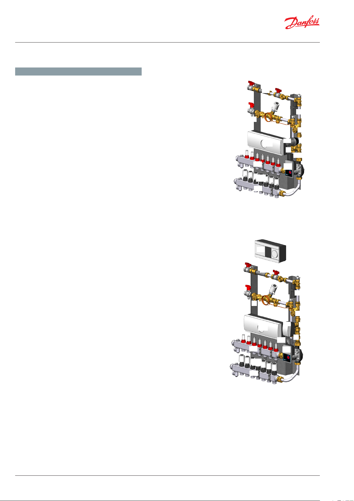
Typ SGM: Verteilersysteme mit AB-PM Strangdifferenzdruckregler
mit Durchflussbegrenzung und integriertem Regelventil, SS-FH
Fußbodenverteiler, Sicherheitsthermostat STW 55°C, TWA, Entlüftungsventile und Schmutzfänger im Vorlauf und Rücklauf.
ENGLISH - GB
Typ e
SGM: Distribution systems with AB-PM a combined automatic
balancing valve with flow limiter and integrated control valve,
SS-FH manifold, safety thermostat STW 55°C, TWA, air vents and
strainer in supply and return.
GERMAN - DE
Typ SGCM : Verteilersysteme mit AB-PM Strangdifferenzdruckregler
mit Durchflussbegrenzung und integriertem Regelventil, SS-FH
Fußbodenverteiler, Sicherheitsthermostat STW 55°C, TWA, Entlüftungsventile und Schmutzfänger im Vorlauf und Rücklauf. Mit
Einzelraumregelung.
ENGLISH - GB
Typ e
SGCM: Distribution systems with AB-PM a combined automatic
balancing valve with flow limiter and integrated control valve, SS-FH
manifold, safety thermostat STW 55°C, TWA, air vents and strainer in
supply and return. With single-room control.
SGM
145H0527, 7 heating circuits
145H0527, 7 Heizkreise
SGCM
145H0547, 7 heating circuits
145H0547, 7 Heizkreise
GERMAN - DE
Typ SGTZ M: Verteilersysteme mit AB-PM Strangdifferenzdruckregler
mit Durchflussbegrenzung und integriertem Regelventil, SS-FH
Fußbodenverteiler, Sicherheitsthermostat STW 55°C, High-TempAnschluss, TWA, Entlüftungsventile und Schmutzfänger im Vorlauf
und Rücklauf. Mit thermostatischem Mischkreis und
Hocheffizienzpumpe.
ENGLISH - GB
Typ e
SGTZM: Type SGTCM: Distribution systems with AB-PM a
combined automatic balancing valve with flow limiter and integrated
control valve, SS-FH manifold, safety thermostat STW 55°C, Hightemperature connection, TWA, air vents and strainer in supply and
return. With thermostatic mixing circuit and high efficiency pump.
SGTZM
145H0567, 7 heating circuits
145H0567, 7 Heizkreise
VI.LZ.P1.5B
© Danfoss | Produced by Danfoss Redan A/S | 2017.05 | 7
Page 8

Montageanleitung / Installation Guide Verteilersysteme / distribution units - Multifamily
4. PRODUKTVORSTELLUNG / PRODUCT INTRODUKTION
GERMAN - DE
Typ SGTZCM: Verteilersystem mit AB-PM Strangdifferenzdruckregler
mit Durchflussbegrenzung und integriertem Regelventil, SS-FH
Manifold, Sicherheitsthermostat STW 55°C, High-Temp-Anschluss,
TWA, Entlüftungsventile und Schmutz fänger im Vorlauf und Rücklauf.
Mit thermostatischem Mischkreis, Hocheffizienzpumpe und Einzelraumregelung.
ENGLISH - GB
Typ e
SGTZCM: Distribution systems with AB-PM a combined automatic
balancing valve with flow limiter and integrated control valve, SS-FH
manifold, safety thermostat STW 55°C, High-temperature connection,
TWA, air vents and strainer in supply and return. With thermostatic
mixing circuit, high efficienty pump and single-room control.
GERMAN - DE
Typ E-SGTZCM: Verteilersystem mit AB-PM Strangdifferenzdruckregler
mit Durchflussbegrenzung und integriertem Regelventil, SS-FH
Manifold, Sicherheitsthermostat STW 55°C, High-Temp-Anschluss,
TWA, Entlüftungsventile und Schmutzfänger im Vorlauf und Rücklauf.
Mit elektronisch geregeltem Mischkreis, Hocheffizienzpumpe und
Einzelraumregelung.
ENGLISH - GB
Typ e
E-SGTZCM: Distribution systems with AB-PM a combined
automatic balancing valve with flow limiter and integrated control
valve, SS-FH manifold, safety thermostat STW 55°C, High-temperature
connection, TWA, air vents and strainer in supply and return. With
electronic mixing circuit, high efficienty pump and single-room control.
SGTZCM
145H0587, 7 heating circuits
145H0587, 7 Heizkreise
E-SGTZCM
145H0607, 7 heating circuits
145H0607, 7 Heizkreise
GERMAN - DE
Die Losungen SGTZM, SGTZCM und E-SGTZCM sind mit Anschlüssen
fur einen Hochtemperaturkreis im Vor- und Rucklauf versehen und
ermoglichen dadurch den Betrieb eines Handtuchheizkorpers mit
einer hoheren Vorlaufttemperatur (ca. 60-70°) als die Vorlauftemperatur
der Fussbodenheizung, die ca. 45° nicht uberschreiten sollte.
ENGLISH - GB
The solutions SGTZM, SGTZCM and E-SGTZCM are supplied with
high-temperature connection in district heatung supply and return
and thereby enables connection of a towel dryer with a higher supply
temperature (approx. 60-70°) than the supply temperature for the
floor heating circuit, which must never exceed approx. 45°.
8 | © Danfoss | Produced by Danfoss Redan A/S | 2017.05
VI.LZ.P1.5B
Page 9

Montageanleitung / Installation Guide Verteilersysteme / distribution units - Multifamily
4. PRODUKTVORSTELLUNG / PRODUCT INTRODUKTION
Basic type Bestell-Nr.
Typ SGM, mit 2 Heizkreisen 145H0522
Typ SGM, mit 3 Heizkreisen 145H0523
Typ SGM, mit 4 Heizkreisen 145H0524
Typ SGM, mit 5 Heizkreisen 145H0525
Typ SGM, mit 6 Heizkreisen 145H0526
Typ SGM, mit 7 Heizkreisen 145H0527
Typ SGM, mit 8 Heizkreisen 145H0528
Typ SGM, mit 9 Heizkreisen 145H0529
Typ SGM, mit 10 Heizkreisen 145H0530
Typ SGM, mit 11 Heizkreisen 145H0531
Typ SGM, mit 12 Heizkreisen 145H0532
Typ SGCM, mit 2 Heizkreisen, mit Einzelraumregelung 145H0542
Typ SGCM, mit 3 Heizkreisen, mit Einzelraumregelung 145H0543
Typ SGCM, mit 4 Heizkreisen, mit Einzelraumregelung 145H0544
Typ SGCM, mit 5 Heizkreisen, mit Einzelraumregelung 145H0545
Typ SGCM, mit 6 Heizkreisen, mit Einzelraumregelung 145H0546
Typ SGCM, mit 7 Heizkreisen, mit Einzelraumregelung 145H0547
Typ SGCM, mit 8 Heizkreisen, mit Einzelraumregelung 145H0548
Typ SGCM, mit 9 Heizkreisen, mit Einzelraumregelung 145H0549
Typ SGCM, mit 10 Heizkreisen, mit Einzelraumregelung 145H0550
Typ SGCM, mit 11 Heizkreisen, mit Einzelraumregelung 145H0551
Typ SGCM, mit 12 Heizkreisen, mit Einzelraumregelung 145H0552
Typ SGTZM, mit 2 Heizkreisen, mit thermostatischem Mischkreis 145H0562
Typ SGTZM, mit 3 Heizkreisen, mit thermostatischem Mischkreis 145H0563
Typ SGTZM, mit 4 Heizkreisen, mit thermostatischem Mischkreis 145H0564
Typ SGTZM, mit 5 Heizkreisen, mit thermostatischem Mischkreis 145H0565
Typ SGTZM, mit 6 Heizkreisen, mit thermostatischem Mischkreis 145H0566
Typ SGTZM, mit 7 Heizkreisen, mit thermostatischem Mischkreis 145H0567
Typ SGTZM, mit 8 Heizkreisen, mit thermostatischem Mischkreis 145H0568
Typ SGTZM, mit 9 Heizkreisen, mit thermostatischem Mischkreis 145H0569
Typ SGTZM, mit 10 Heizkreisen, mit thermostatischem Mischkreis 145H0570
Typ SGTZM, mit 11 Heizkreisen, mit thermostatischem Mischkreis 145H0571
Typ SGTZM, mit 12 Heizkreisen, mit thermostatischem Mischkreis
Typ SGTZCM, mit 2 Heizkreisen, thermostatischer Mischkreis, Einzelraumregelung
Typ SGTZCM, mit 3 Heizkreisen, thermostatischer Mischkreis, Einzelraumregelung 145H0583
Typ SGTZCM, mit 4 Heizkreisen, thermostatischer Mischkreis, Einzelraumregelung 145H0584
Typ SGTZCM, mit 5 Heizkreisen, thermostatischer Mischkreis, Einzelraumregelung 145H0585
Typ SGTZCM, mit 6 Heizkreisen, thermostatischer Mischkreis, Einzelraumregelung 145H0586
Typ SGTZCM, mit 7 Heizkreisen, thermostatischer Mischkreis, Einzelraumregelung 145H0587
Typ SGTZCM, mit 8 Heizkreisen, thermostatischer Mischkreis, Einzelraumregelung 145H0588
Typ SGTZCM, mit 9 Heizkreisen, thermostatischer Mischkreis, Einzelraumregelung 145H0589
Typ SGTZCM, mit 10 Heizkreisen, thermostatischer Mischkreis, Einzelraumregelung 145H0590
Typ SGTZCM, mit 11 Heizkreisen, thermostatischer Mischkreis, Einzelraumregelung 145H0591
Typ SGTZCM, mit 12 Heizkreisen, thermostatischer Mischkreis, Einzelraumregelung 145H0592
Typ E-SGTZCM, mit 2 Heizkreisen, elektronischer Mischkreis, Einzelraumregelung 145H0602
Typ E-SGTZCM, mit 3 Heizkreisen, elektronischer Mischkreis, Einzelraumregelung 145H0603
Typ E-SGTZCM, mit 4 Heizkreisen, elektronischer Mischkreis, Einzelraumregelung 145H0604
Typ E-SGTZCM, mit 5 Heizkreisen, elektronischer Mischkreis, Einzelraumregelung 145H0605
Typ E-SGTZCM, mit 6 Heizkreisen, elektronischer Mischkreis, Einzelraumregelung 145H0606
Typ E-SGTZCM, mit 7 Heizkreisen, elektronischer Mischkreis, Einzelraumregelung 145H0607
Typ E-SGTZCM, mit 8 Heizkreisen, elektronischer Mischkreis, Einzelraumregelung 145H0608
Typ E-SGTZCM, mit 9 Heizkreisen, elektronischer Mischkreis, Einzelraumregelung 145H0609
Typ E-SGTZCM, mit 10 Heizkreisen, elektronischer Mischkreis, Einzelraumregelung 145H0610
Typ E-SGTZCM, mit 11 Heizkreisen, elektronischer Mischkreis, Einzelraumregelung 145H0611
Typ E-SGTZCM, mit 12 Heizkreisen, elektronischer Mischkreis, Einzelraumregelung 145H0612
145H0572
145H0582
Unterputzkasten Bestell-Nr.
Unterputzkasten H 910 x B 690 x T 150 mm 145H4335
Tür für Unterputzkasten 145H4335, H 910 x B 690 mm 145H4025
Unterputzkasten H 910 x B 850 x T 150 mm 145H4281
Tür für Unterputzkasten 145H4281, H 910 x B 850 mm 145H4297
VI.LZ.P1.5B
© Danfoss | Produced by Danfoss Redan A/S | 2017.05 | 9
Page 10

Montageanleitung / Installation Guide Verteilersysteme / distribution units - Multifamily
4. PRODUKT INTRODUKTION / PRODUCT INTRODUKTION
Basic type Code No
Type SGM, with 2 heating circuits 145H0522
Type SGM, with 3 heating circuits 145H0523
Type SGM, with 4 heating circuits 145H0524
Type SGM, with 5 heating circuits 145H0525
Type SGM, with 6 heating circuits 145H0526
Type SGM, with 7 heating circuits 145H0527
Type SGM, with 8 heating circuits 145H0528
Type SGM, with 9 heating circuits 145H0529
Type SGM, with 10 heating circuits 145H0530
Type SGM, with 11 heating circuits 145H0531
Type SGM, with 12 heating circuits 145H0532
Type SGCM, with 2 heating circuits, with single-room control 145H0542
Type SGCM, with 3 heating circuits, with single-room control 145H0543
Type SGCM, with 4 heating circuits, with single-room control 145H0544
Type SGCM, with 5 heating circuits, with single-room control 145H0545
Type SGCM, with 6 heating circuits, with single-room control 145H0546
Type SGCM, with 7 heating circuits, with single-room control 145H0547
Type SGCM, with 8 heating circuits, with single-room control 145H0548
Type SGCM, with 9 heating circuits, with single-room control 145H0549
Type SGCM, with 10 heating circuits, with single-room control 145H0550
Type SGCM, with 11 heating circuits, with single-room control 145H0551
Type SGCM, with 12 heating circuits, with single-room control 145H0552
Type SGTZM, with 2 heating circuits, with thermostatic mixing loop 145H0562
Type SGTZM, with 3 heating circuits, with thermostatic mixing loop 145H0563
Type SGTZM, with 4 heating circuits, with thermostatic mixing loop 145H0564
Type SGTZM, with 5 heating circuits, with thermostatic mixing loop 145H0565
Type SGTZM, with 6 heating circuits, with thermostatic mixing loop 145H0566
Type SGTZM, with 7 heating circuits, with thermostatic mixing loop 145H0567
Type SGTZM, with 8 heating circuits, with thermostatic mixing loop 145H0568
Type SGTZM, with 9 heating circuits, with thermostatic mixing loop 145H0569
Type SGTZM, with 10 heating circuits, with thermostatic mixing loop 145H0570
Type SGTZM, with 11 heating circuits, with thermostatic mixing loop 145H0571
Type SGTZM, with 12 heating circuits, with thermostatic mixing loop
Type SGTZCM, with 2 heating circuits, thermostatic mixing circuit, single room control
Type SGTZCM, with 3 heating circuits, thermostatic mixing circuit, single room control 145H0583
Type SGTZCM, with 4 heating circuits, thermostatic mixing circuit, single room control 145H0584
Type SGTZCM, with 5 heating circuits, thermostatic mixing circuit, single room control 145H0585
Type SGTZCM, with 6 heating circuits, thermostatic mixing circuit, single room control 145H0586
Type SGTZCM, with 7 heating circuits, thermostatic mixing circuit, single room control 145H0587
Type SGTZCM, with 8 heating circuits, thermostatic mixing circuit, single room control 145H0588
Type SGTZCM, with 9 heating circuits, thermostatic mixing circuit, single room control 145H0589
Type SGTZCM, with 10 heating circuits, thermostatic mixing circuit, single room control 145H0590
Type SGTZCM, with 11 heating circuits, thermostatic mixing circuit, single room control 145H0591
Type SGTZCM, with 12 heating circuits, thermostatic mixing circuit, single room control 145H0592
Type E-SGTZCM, with 2 heating circuits, electronic mixing circuit, single room control 145H0602
Type E-SGTZCM, with 3 heating circuits, electronic mixing circuit, single room control 145H0603
Type E-SGTZCM, with 4 heating circuits, electronic mixing circuit,single room control 145H0604
Type E-SGTZCM, with 5 heating circuits, electronic mixing circuit, single room control 145H0605
Type E-SGTZCM, with 6 heating circuits, electronic mixing circuit, single room control 145H0606
Type E-SGTZCM, with 7 heating circuits, electronic mixing circuit, single room control 145H0607
Type E-SGTZCM, with 8 heating circuits, electronic mixing circuit, single room control 145H0608
Type E-SGTZCM, with 9 heating circuits, electronic mixing circuit, single room control 145H0609
Type E-SGTZCM, with 10 heating circuits, electronic mixing circuit, single room control 145H0610
Type E-SGTZCM, with 11 heating circuits, electronic mixing circuit, single room control 145H0611
Type E-SGTZCM, with 12 heating circuits, electronic mixing circuit, single room control 145H0612
145H0572
145H0582
Recess boxes Code No
Recess box H 910 x W 690 x D 150 mm 145H4335
Door for recess box 145H4335, H 910 x W 690 mm 145H4025
Recess box H 910 x W 850 x D 150 mm 145H4281
Door for recess box 145H4281, H 910 x W 850 mm 145H4297
10 | © Danfoss | Produced by Danfoss Redan A/S | 2017.05
VI.LZ.P1.5B
Page 11

Montageanleitung / Installation Guide Verteilersysteme / distribution units - Multifamily
5. SCHALTPLÄNE / DIAGRAMS
SGM SGCM
DH Return
FW Rücklauf
DHSupply
FW Vorlauf
FH Supply
FH Vorlauf
Anzahl von Heizkreisen variiert
FH Return
Number of heating circuits may vary
FH Rücklauf
SGTZM
DH Return
SGTZCM
FW Rücklauf
DHSupply
FW Vorlauf
DH Return
FW Rücklauf
DHSupply
FW Vorlauf
FH Supply
FH Vorlauf
FH Return
FH Rücklauf
DH Return
FW Rücklauf
DHSupply
FW Vorlauf
Anzahl von Heizkreisen variiert
Number of heating circuits may vary
FH Supply
FH Vorlauf
FH Return
FH Rücklauf
ESGTZCM
FH Supply
FH Vorlauf
FH Return
FH Rücklauf
DH Return
FW Rücklauf
DHSupply
FW Vorlauf
Anzahl von Heizkreisen variiert
Number of heating circuits may vary
Anzahl von Heizkreisen variiert
Number of heating circuits may vary
FH Supply
FH Vorlauf
FH Return
FH Rücklauf
Anzahl von Heizkreisen variiert
Number of heating circuits may vary
4 Strangdifferenzdruckregler mit Durchflussbegrenzung AB-PM /
Combined automatic balancing valve with flow limiter and integrated control
valve, AB-PM
5 Schmutzfänger / Strainer
6 Rückschlagklappe / Non-return valve
7A Kugelhahn / Ball valve
7B Kugelhahn mit Fühlertasche / Ball valve with sensor pocket
7C Kugelhahn / Ball valve
10 Umwälzpumpe WILO YONOS 15/6 230V / Circulation pump Wilo Yonos 15/6
230V
17 Air vent / Entlüftung
19 Entleerungshahn mit manueller Entlüftung / Tapping point with manual air
vent
24 Passstück für Wärmemengenzähler / Fitting piece for heat meter
25 Elektronische Regler ECL Comfort / Electronic controller ECL Comfort
27 Anlegefühler / Sensor
29 FTC Thermostat oder Stellantrieb AMV) / FTC thermostat or AMV actuator)
30 Stellventil (RA-C oder VS2) / Valve (RA-C or VS2)
33 Anschluß Hochtemperaturkreis / High-temperature connection
52 Thermischer Stellantrieb TWA-Z / Thermal actuator TWA-Z
54 Sicherheitsthermostat / Safety thermostat
57 Netzstecker / Plug
58 Anschlussverteiler mit Durchflussmesser / Manifold with flow meter
90 Hauptregler Danfoss FH-WC / Hard-wired Master controller Danfoss FH-WC
90A Thermische Stellantrieb Danfoss TWA-A 230V / Thermal actuator Danfoss
TWA-A 230V
VI.LZ.P1.5B
© Danfoss | Produced by Danfoss Redan A/S | 2017.05 | 11
Page 12

Montageanleitung / Installation Guide Verteilersysteme / distribution units - Multifamily
6. MASSSKIZZE & ANSCHLUSS / DIMENSIONAL SKETCH & CONNECTION
MASSSKIZZE / DIMENSIONAL SKETCH
DH Return
FW Rücklauf
DHSupply
FW Vorlauf
754
FH Supply
FH Vorlauf
DH Return
FW Rücklauf
DHSupply
FW Vorlauf
FH Supply
FH Vorlauf
FH Return
FH Rücklauf
FH Return
FH Rücklauf
593
DH Return
FW Rücklauf
DHSupply
FW Vorlauf
FH Supply
FH Vorlauf
129
12 | © Danfoss | Produced by Danfoss Redan A/S | 2017.05
FH Return
FH Rücklauf
VI.LZ.P1.5B
Page 13

Montageanleitung / Installation Guide Verteilersysteme / distribution units - Multifamily
7. HAUPTKOMPONENTEN & ANSCHLUSS / MAIN COMPONENTS & CONNECTION
GERMAN - DE / ENGLISH - UK
4 Strangdifferenzdruckregler mit Durchflussbegrenzung AB-PM /
Combined automatic balancing valve with flow limiter and integrated
control valve, AB-PM
5 Schmutzfänger / Strainer
7A Kugelhahn / Ball valve
7B Kugelhahn mit Fühlertasche / Ball valve with sensor pocket
7C Kugelhahn / Ball valve
10 Umwälzpumpe WILO YONOS 15/6-130 230V / Circulation pump Wilo
Yonos 15/6-130 230V
17 Entlüftung / Air vent
19 Entleerungshahn und manueller Entlüfter / Tapping point with
manual air vent
24 Paßstück für Wärmemengenzähler / Fitting piece for heat meter
29 FTC Thermostat oder Stellantrieb AMV / FTC thermostat or actuator
AMV
30 Stellventil (RA-C oder VS2) / Valve (RA-C or VS2)
31 Thermischer Stellantrieb TWA-Z / Thermal actuator T WA-Z
33 Anschluß Hochtemperaturkreis / High-temperature connection
54 Sicherheitsthermostat / Safety thermostat
58 Anschlussverteiler mit Durchflussmesser / Manifold with flow meter
90 Hauptregler Danfoss FH-WC / Hard-wired Master controller Danfoss
FH-WC
90A Thermischer Stellantrieb Danfoss TWA-A 230V / Thermal actuator
Danfoss TWA-A 230V
SGM
SGCM
7A
7B
19
58
19
58
145H0527, 7 heating circuits
145H0527, 7 Heizkreise
7A
7B
7C
24
52
17
45
54
7C
24
52
4
5
17
54
5
17
54
17
5
SGTZM
19
58
19
19
90A
58
145H0547, 7 heating circuits
145H0547, 7 Heizkreise
7A
7B
5
58
90
24
52
54
7C
17
33
54
17
4
33
29
5
30
6
54
10
VI.LZ.P1.5B
19
58
145H0567, 7 heating circuits
145H0567, 7 Heizkreise
© Danfoss | Produced by Danfoss Redan A/S | 2017.05 | 13
Page 14
Montageanleitung / Installation Guide Verteilersysteme / distribution units - Multifamily
7. HAUPTKOMPONENTEN & ANSCHLUSS / MAIN COMPONENTS & CONNECTION
GERMAN - DE / ENGLISH - UK
4 Strangdifferenzdruckregler mit Durchflussbegrenzung AB-PM /
Combined automatic balancing valve with flow limiter and
integrated control valve, AB-PM
5 Schmutzfänger / Strainer
6 Rückschlagklappe / Non-return valve
7A Kugelhahn / Ball valve
7B Kugelhahn mit Fühlertasche / Ball valve with sensor pocket
7C Kugelhahn / Ball valve
10 Pumpe WILO YONOS 15/6-130 230V / Circulation pump Wilo
Yonos 15/6-130 230V
17 Entlüftung / Air vent
19 Entleerungshahn und manueller Entlüfter / Tapping point with
manual Air vent
24 Paßstück für Wärmemengenzähler / Fitting piece for heat meter
25 Elektronische Regler ECL Comfort / Electronic controller ECL
Comfort
27 Anlegefühler / Sensor
29 FTC Thermostat oder Stellantrieb AMV / FTC thermostat or
actuator AMV
30 Stellventil (RA-C oder VS2) / Valve (RA-C or VS2)
31 Thermischer Stellantrieb TWA-Z / Thermal actuator T WA-Z
33 Anschluß Hochtemperaturkreis / High-temperature connection
54 Sicherheitsthermostat / Safety thermostat
57 Netzstecker / Plug
58 Anschlussverteiler mit Durchflussmesser / Manifold with flow
meter
90 Hauptregler Danfoss FH-WC / Hard-wired Master controller
Danfoss FH-WC
90A Thermischer Stellantrieb Danfoss TWA-A 230V / Thermal actuator
Danfoss TWA-A 230V
SGTZCM
E-SGTZCM
7A
7B
5
19
19
145H0587, 7 heating circuits
145H0587, 7 Heizkreise
7A
7B
5
58
90A
58
25
24
24
52
90
4
52
4
33
33
7C
33
7C
17
33
17
29
54
5
30
6
54
10
54
5
17
17
14 | © Danfoss | Produced by Danfoss Redan A/S | 2017.05
19
19
90
58
90A
58
145H0607, 7 heating circuits
145H0607, 7 Heizkreise
29
54
10
30
6
VI.LZ.P1.5B
Page 15
Montageanleitung / Installation Guide Verteilersysteme / distribution units - Multifamily
8. MONTAGE / MOUNTING
GERMAN - DE
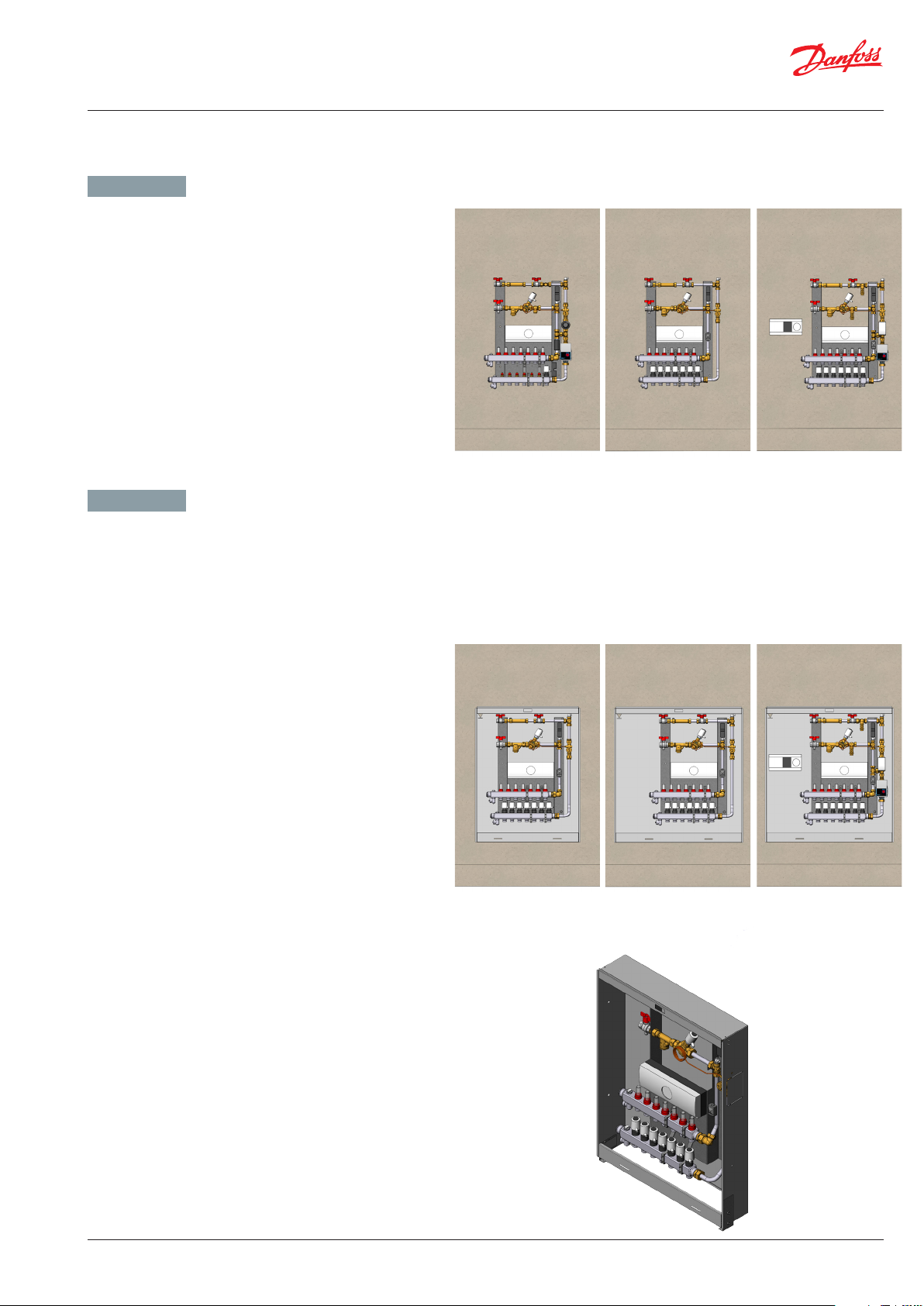
Die Systeme können in Unterputzausführung mit Einbauschrank
oder in Aufputzausführung direkt auf der Wand montiert
werden.
Einbauschränke für Unterputzausführung sind in zwei Größen
erhältlich
2-8 Kreise passen in den:
145H4335 Unterputzschrank H910/B690/T150 mm
9-12 Kreise passen in den:
145H4281 Unterputzschrank H910/B850/T150 mm
Montage auf der Wand / Mounting on wall
ENGLISH - GB
The distributors fits on the back plate of the recess boxes
and also be mounted on the wall.
The systems can be mounted in the wall in a recess box or
directly on the wall.
Recess boxes for built-in variants are available in two sizes:
2-8 circuits fits the:
145H4335: Recess box H910/W690/D150 mm
9-12 circuits fit the:
145H4281 Recess box H910/W850/D150 mm
Unterputzmontage in Einbauschrank / Recess mounting in recess box
VI.LZ.P1.5B
© Danfoss | Produced by Danfoss Redan A/S | 2017.05 | 15
Page 16
Montageanleitung / Installation Guide Verteilersysteme / distribution units - Multifamily
9. MONTAGE IM EINBAUSCHRANK / MOUNTING IN RECESS BOX
GERMAN - DE
Montage
Schließen Sie das Verteilersystem gemäß der folgenden Instruktion
und/oder gemäß den Hinweisen in dieser Anleitung an die Hausverrohrung an.
ENGLISH - GB
Mounting
Connect the distribution system to the household piping in accordance
with the labelling on the unit and/or in accordance with the instructions in this manual.
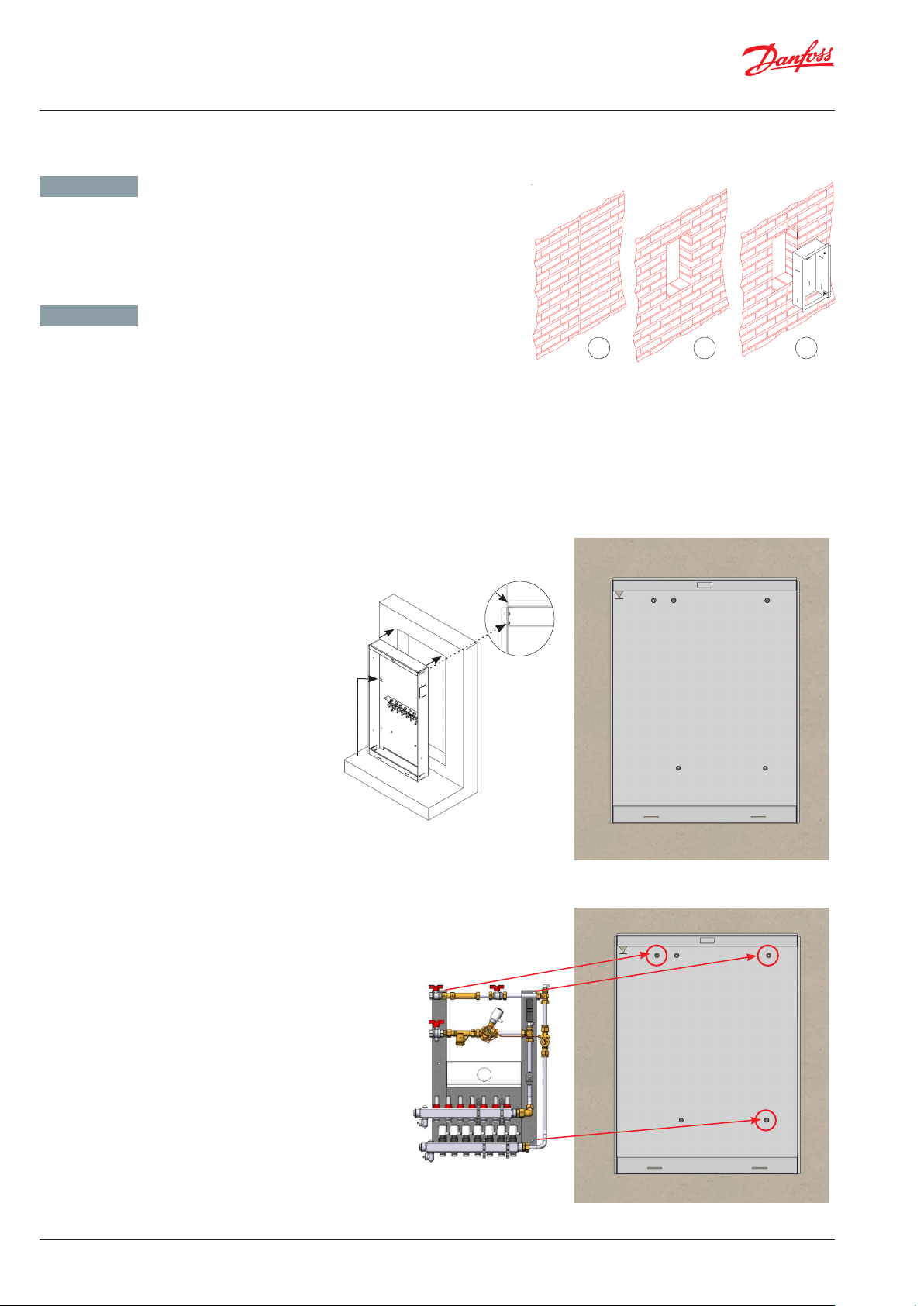
Schritt
Unterputzschrank wird eingemauert
oder in Leichtbauwand eingebaut.
Wall
Wand
Mur
1
1 2 3
Step
Recess box with rotatable mounting rail is
immured or built into lightweight partition wall
Schritt
Station wird in Unterputzschrank gelegt und mit 3
Muttern M8 und 3 Beilagscheiben M8x30 mm am
Einbauschrank befestigt.
Step
Mount unit into position with 3 M8 nuts and 3 washers
M8x30.
1000 mm
2
16 | © Danfoss | Produced by Danfoss Redan A/S | 2017.05
VI.LZ.P1.5B
Page 17
Montageanleitung / Installation Guide Verteilersysteme / distribution units - Multifamily
9. MONTAGE IM EINBAUSCHRANK / MOUNTING IN RECESS BOX
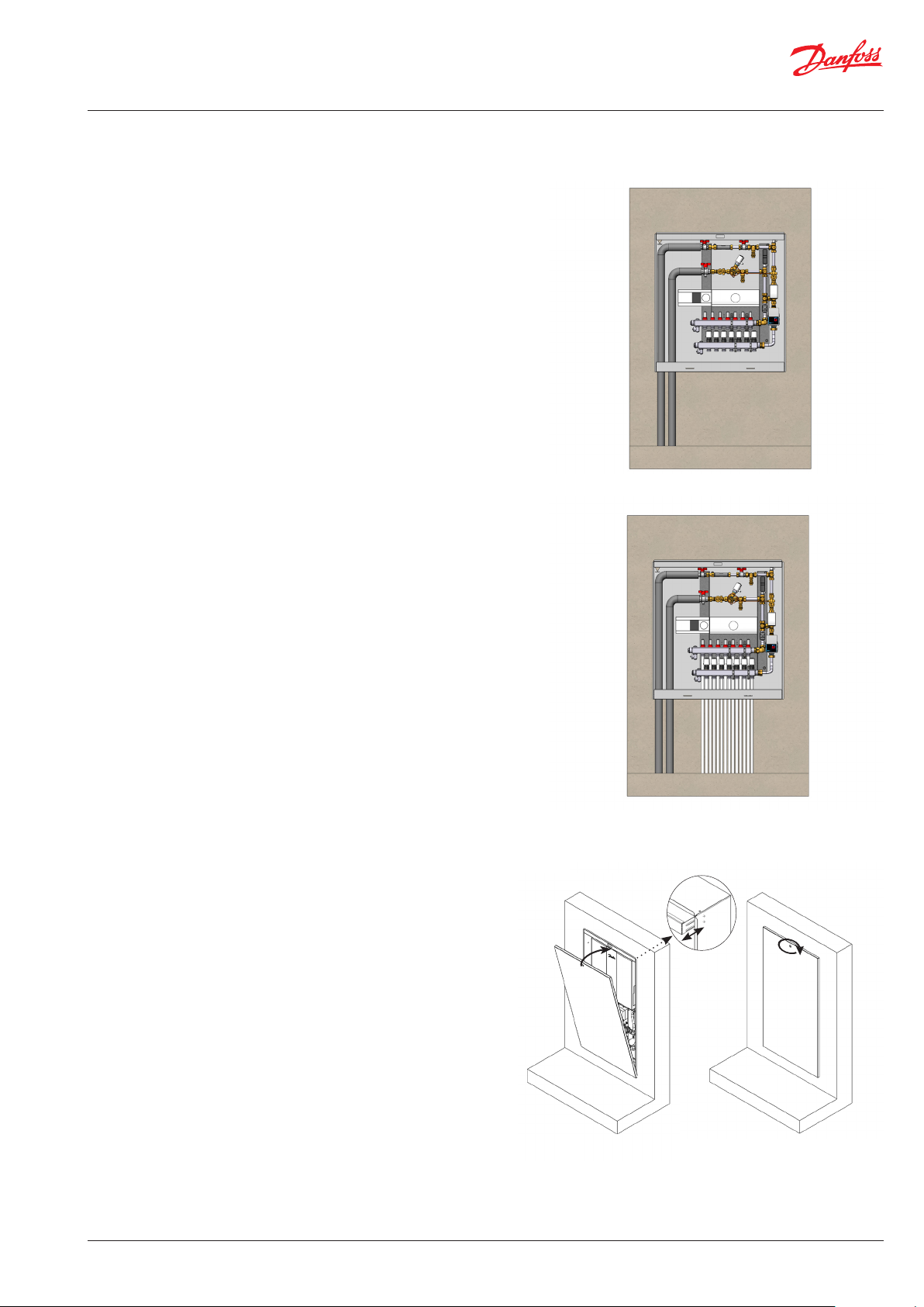
Schritt
Der Installateuer schließt die Hausverrohrung für FW Vorlauf und FW
Rücklauf an, und isoliert die Rohrleitungen.
Beachten Sie bitte immer bei der Einbau, daß genug Platz für
Rohranschluß ist.
Step
Installer connects the household pipes for DH supply and DH
return and insulates the pipes.
When installing, please ensure that there is enough space for
pipe connection.
Schritt
Befestigen Sie die Fußbodenheizungs-PEX-Rohre
ordnungsgemäß am Verteilerrohre.
Step
Fasten the floorheating PEX pipes properly to the manifolds.
Schritt
Tür wird montiert.
Beachten Sie bitte:
Schutzfolie auf dem Tür entfernen!
Step
Mount door.
Please note:
Remove protective foil on door!
VI.LZ.P1.5B
© Danfoss | Produced by Danfoss Redan A/S | 2017.05 | 17
Page 18
Montageanleitung / Installation Guide Verteilersysteme / distribution units - Multifamily
10. EINSTELLUNG UND INBETRIEBNAHME / ADJUSTMENT AND COMMISSIONING
GERMAN - DE ENGLISH - GB
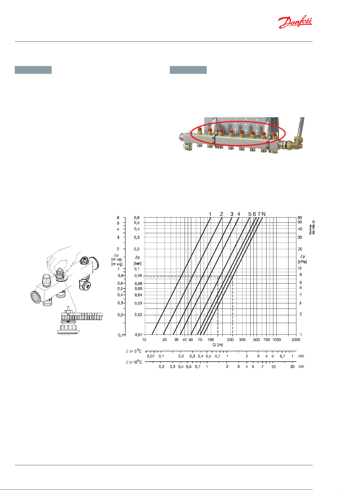
Verteiler mit Anschlüssen, mit Durchflussmesser
Durchflussmenge läss sich durch Drehen des Durchflussmessers
einstellen. Siehe bitte beigelegte Abbildungen.
Manifold with connecting pieces, with flow meter
Flow rate can be adjusted by turning the flowmeter. Please see enclosed pictures.
18 | © Danfoss | Produced by Danfoss Redan A/S | 2017.05
VI.LZ.P1.5B
Page 19

Montageanleitung / Installation Guide Verteilersysteme / distribution units - Multifamily
VI.LZ.P1.5B
von oben
© Danfoss | Produced by Danfoss Redan A/S | 2017.05 | 19
Page 20
Montageanleitung / Installation Guide Verteilersysteme / distribution units - Multifamily
10. EINSTELLUNG UND INBETRIEBNAHME / ADJUSTMENT AND COMMISSIONING
GERMAN - DE ENGLISH - GB
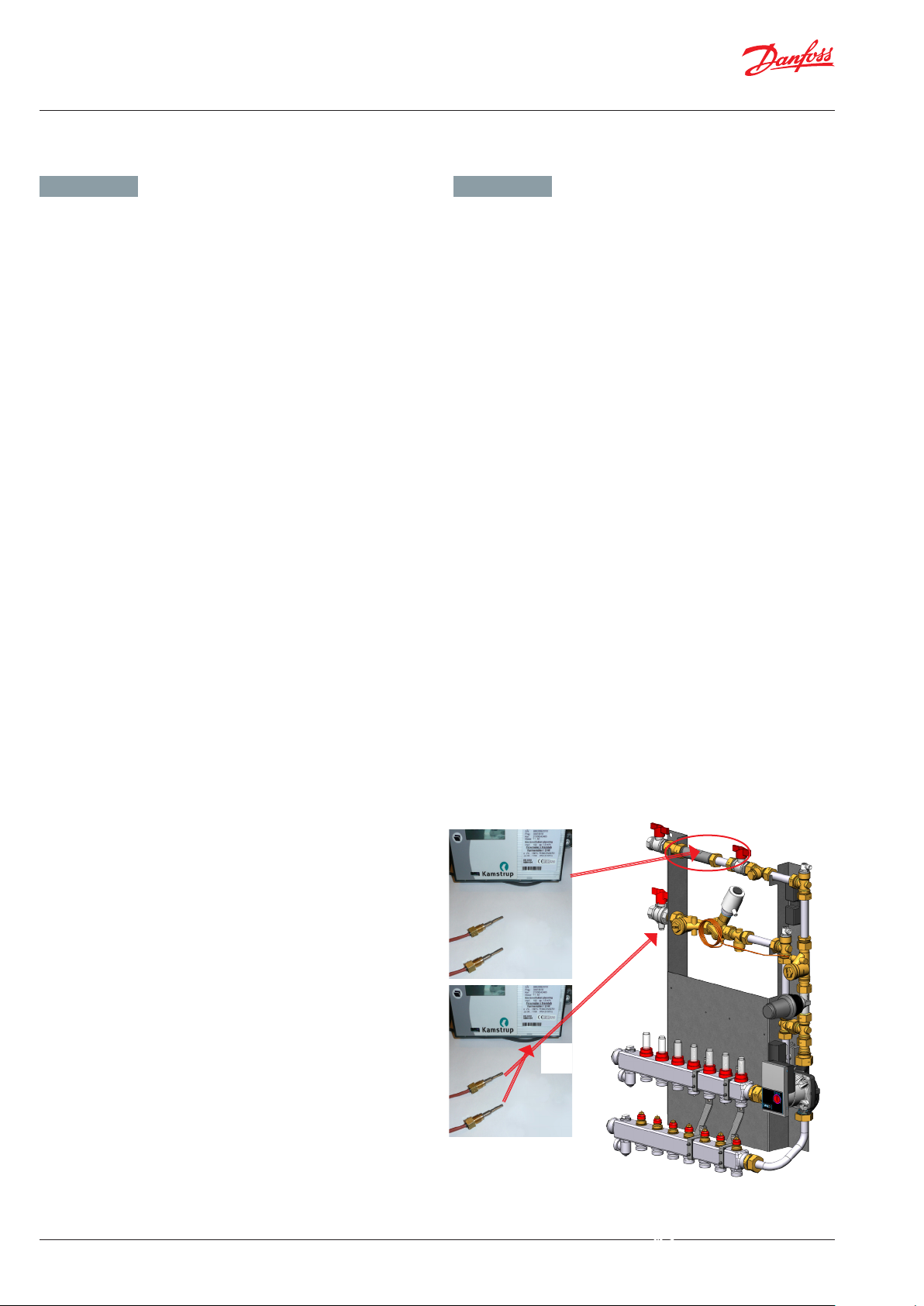
Wärmemengenzähler, Passstücke
Die Stationen sind mit Passstück für den Einbau eines Wärmemengenzählers in FW Rücklauf ausgerüstet.
Montage des Wärmemengenzählers
- Die Kugelhähne auf der Fernwärme- und Heizungsseiten
schließen.
- Verschraubungen (Mutter) am Passstück lösen und
Passstück entfernen.
- Wärmemengenzähler einsetzen und verschrauben Dichtungen nicht vergessen.
- Fühler einbauen - Dichtungen nicht vergessen.
- Nach Montage des Wärmemengenzählers sind alle Gewinde -
anschlüsse zu kontrollieren und gegebenenfalls nachzuziehen.
Der Wärmezähler besteht im Wesentlichen aus einem Durchflusszähler, zwei Temperaturfühlern für Einbau in Vor- und Rücklauf
sowie einem Mikroprozessor-Rechenwerk mit einem Display, auf
dem die verbrauchte Energie ablesbar ist.
Montage des Temperaturfühlers
Als Standard ist der Wärmezähler mit Temperaturfühlern für Rücklauftemperaturmessung versehen.
Die Multifamily Stationen sind mit Fühlertasche mit Anschluss
M10x1 für Direkteinbau des Temperaturfühlers in primär Vorlauf
ausgestattet (siehe Unten):
- Das Stopfen im Fühlertaschen abbauen, Pos. A.
- Der eine Temperaturfühler in die Fühlertasche einstecken
- Der Überwurfmutter des Fühlers festschrauben
Heat meter, fitting piece.
The units are equipped with fixed fitting piece size ¾” x 110 mm
for fitting of heat meter in the district heating return line.
Fitting of heat meter
- Close the ball valves on the district heating and the heating
sides.
- Loosen the union nuts at both ends of the fitting piece and
remove it.
- Fit the heat meter, - remember to insert gaskets.
- Mount sensor, - remember to insert gaskets.
- After mounting of heat meter remember to check and tighten
all pipe connections before commissioning the substation.
The heat meter consists of flow meter, two temperature sensors and
a microprocessor calculator for the calculation of energy consumption. On the LCD display of the calculator the energy consumption
can be read.
Mounting of temperature sensors
As standard the heat meter is supplied with temperature sensors
for measuring the return flow temperatures.
The multifamily units are prepared for mounting of temperature
sensors with M10x1 connection (see photoes below):
The supply flow sensor is mounted in the sensor pocket on DH
supply (pos A.)
- demount M10 plug (Pos. A)
- insert one temperature sensor in the sensor pocket
- tighten temperature sensor union nut
Der andere Fühler im Wärmemengenzählergehäuse auf FW Rücklauf
einbauen und festschrauben (Pos B).
Mount the return flow sensor in the heat meter housing (pos. B).
A
B
20 | © Danfoss | Produced by Danfoss Redan A/S | 2017.05
VI.LZ.P1.5B
Page 21
Montageanleitung / Installation Guide Verteilersysteme / distribution units - Multifamily
10. EINSTELLUNG UND INBETRIEBNAHME / ADJUSTMENT AND COMMISSIONING
GERMAN - DE ENGLISH - GB
Elektrischer Anschluss
Der elektrische Anschluss des Systems darf nur von autorisiertem
Personal durchgeführt werden.
Die Station muss an eine Netzversorgung mit 230 VAC angeschlossen werden.
Die Stromversorgung/der Anschluss muss gemäß den geltenden
Vorschriften und Anweisungen eingerichtet/vorgenommen werden.
Die Station muss an einen externen Schalter angeschlossen werden,
sodass sie für Wartungs-, Reinigungs und Reparaturarbeiten oder
bei Notfällen vom Netz getrennt werden kann.
Nicht vergessen, Potentialausgleich gemäß den geltenden lokalen
Vorschriften ausführen.
Montage von Außentemperaturfühler
Der Außentemperaturfühler wird lose mitgeliefert und muß bauseits
laut Abbildungen montiert werden.
Den Fühler immer an der kältesten gebäudewand (normalerweise
die Nordseite) befestigen.
Der Fühler darf nicht der Morgensonne ausgesetzt sein, und darf
nicht über Fenster, Türen, Luftabzügen oder anderen Wärmequellen,
sowie nicht unter Balkone und Dachtraufen angebracht werden.
Montagehöhe ungefähr 2,5 m über dem Boden.
Temperaturbereich: -50 bis 50° C
Elektrischer Anschluss
Die Leiter können beliebig angeschlossen werden.
Anschlusskabel: 2 x 0,4 - 1,5 mm²
Kabelende am Regler an die Klemmen 29 und 30 anschließen.
Regler / Controller ECL 310
Versorgungsspannung /
Power supply: 230 V a.c. - 50 Hz
Toleranzbereich der
Versorgungsspannung: 207 to 244 V a.c. (IEC 60038)
Leistungsaufnahme /
Power consumption: 5 VA
Belastung der Relaisausgänge /
Load on relay outputs: 4(2) A - 230 V a.c
Belastung der Triac-Ausgänge /
Load on triac outputs: 0,2 A - 230 V a.c.
Electrical connection
The electrical connection of the unit must be performed by aqualified
and authorised electrician in compliance with all applicable rules
and regulations.
The unit should be connected to a 230 V AC power supply.
The power supply / connection must be carried out in accordance
with the applicable regulations and instructions.
The unit must be wired and connected to an external main switchso
that it can be disconnected during maintenance, cleaning and
repairs or in the event of an emergency.
Do not forget to establish potential equalization in accordance
with the applicable regulations and instructions.
Mounting of outdoor sensor
The outdoor temperature sensor is delivered separately and must
be mounted on site according to the enclosed illustrations.
The outdoor sensor is always to be mounted on the coldest side of
the property (normally the north side of the property).
The sensor must not be exposed to the morning sun, and should not
be mounted above windows, doors, air vents or other heat sources,
and not under balconies and roof eaves.
Mounting height approx. 2.5 m above ground.
Temperature range: -50 to 50° C.
Electrical connections
Two wire non polarized (can be crossed).
Sensor cable: 2 x 0.4 - 1.5 mm².
Connect the cable ends to ECL controller in clamps 29 and 30.
Stellantrieb / Actuator AMV 140
Versorgungsspannung /
Power supply: 230 AC; +10 to –15 % - 50/60 Hz
Schutzart / Protection class: IP 42
Leistungsaufnahme /
Power consumption: 8 VA
Pumpe / Pump Yonos Para
Versorgungsspannung /
Power supply: 230 V AC – 50 Hz
Leistungsaufnahme /
Power consumption: Max. 31 Watt
Schutzart / Protection class: IP42
Für weitere Informationen siehe bitte beigelegte Anleitungen /
For further information please refer to the enclosed instructions.
VI.LZ.P1.5B
© Danfoss | Produced by Danfoss Redan A/S | 2017.05 | 21
Page 22

Montageanleitung / Installation Guide Verteilersysteme / distribution units - Multifamily
10. EINSTELLUNG UND INBETRIEBNAHME / ADJUSTMENT AND COMMISSIONING
GERMAN
Generell
Primärseitig sind die Systeme mit einem AB-PM Strangdifferenzdruckregler mit Durchflussbegrenzung ausgestattet, der als einen
Durchflussbegrenzer wirkt und den Durchfluss in Heizungsanlagen
ausgleicht.
Strangdifferenzdruckregler AB-PM mit Durchflussbegrenzung
Das AB-PM ist ein automatisches Kombiventil. Es fungiert als Differenzdruck- und Durchflussregler sowie als Zonenventil. Ein höherer
Druck wirkt auf die Oberseite der Regelmembran (5), während ein
niedrigerer Druck in der Rücklaufleitung dagegen über eine Impulsleitung (9) auf die Unterseite der Membranwirkt. Wenn unter
Teillast der verfügbare Druck steigt, schließt die Membran und sorgt
auf diese Weise für einen konstanten Differenzdruck im geregelten
Strang. Der Differenzdruckregler sorgt für einen konstanten Differenzdruck im geregelten Strang sowie im Reglerteil des AB-PM. Der
Reglerteil des AB-PM wirkt als Durchflussbegrenzer. Dies ermöglicht
die Einstellung des Auslegungsdurchflusses sowie des erforderlichen Differenzdrucks.
Der Durchfluss wird durch die Voreinstellung am AB-PM festgelegt
und basiert auf dem Druckbedarf des Strangs.
Wenn ein Stellantrieb auf dem Ventil montiert wird, lässt sich das
AB-PM als Zonenventil verwenden. Wenn das AB-PM an eine Raumregelung mit Zeitprogrammen angeschlossen wird, sind Funktionen
wie Nachtabsenkung, Urlaubsbetrieb usw. verfügbar.
ENGLISH
Generell
On the primary side the units are supplied with a combined automatic
balancing valve AB-PM, which acts a a flow liiter and balances the
flow in heating installations.
Combined automatic balancing valve AB-PM
AB-PM is a combined automatic balancing valve. It is working as
∆p controller, flow limiter and zone controller. Higher pressure acts
onthe upper side of the control diaphragm (5) while via an impulse
tube (9) lower pressure in the return pipe acts on the lower side of
the diaphragm. When available pressure increases at partial loads,
the membrane closes and thus keeps stable ∆p inside the controlled
loop. ∆p controller keeps constant differential pressure on the
controlled loop including the control part of AB-PM.
The control part of AB-PM is working as a flow limiter. This enables
to set both the design flow as well as needed ∆p. The flow rate is
defined by presetting AB-PM, based on pressure demand of the loop.
With actuator mounted on the valve, AB-PM can be used as zone
valve. When connected to the room controller with time programs,
functions such as night setback, holiday mode, etc become available.
Please refer to enclosed instruction manual for further information.
Siehe bitte beigelegte Instruktionsanleitung für weitere Informationen.
1. Spindel
2. Stopfbuchse
3. Voreinstellring
4. Kegel (Regelventil)
5. Membran
6. Hauptfeder
7. Hohlkegel (Druckregler)
8. Vulkanisierter Sitz (Druckregler)
9. Impulsleitung
1. Spindle
2. Stuffing box
3. Pointer
4. Control valve’s cone
5. Membrane
6. Main spring
7. Hollow cone (pressure controller)
8. Vulcanized seat (pressure controller)
9. Impulse tube
22 | © Danfoss | Produced by Danfoss Redan A/S | 2017.05
VI.LZ.P1.5B
Page 23

Montageanleitung / Installation Guide Verteilersysteme / distribution units - Multifamily
088R0248| 15.12.2005 | Version 03
11. REGELTECHNIK - FUSSBODENHEIZUNG / CONTROL - FLOOR HEATING
GERMAN - DE ENGLISH - GB
Die Verteilersysteme SGCM, SGTZCM und E-SGTZCM sind mit fest
verdrahtetem Heizkreisregler FH-WC 230 V und Thermo-Stellantrieben TWA-A NC gemäß Anzahl der Heizkreise versehen.
Dadurch wird Anschluss an elektronischen programmierbaren
Raumthermostaten ermöglicht.
Zusammen mit dem Raumthermostat wird der Thermo- Stellantrieb
TWA-A zum ON/OF Regelung der Anlage verwendet.
Elektrische Verbindung zwischen Thermo-Stellantrieb TWA-A und
Heizkreisregler FH-WC ist werkseitig hergestellt.
Weitere Verkabelung ist vor Ort herzustellen.
INSTRUCTIONS
TWA-A
For Danfoss RA valves
TWA-V
For Danfoss RAV/VMT valves
TWA NC
The distribution systems
SGCM, SGTZCM and E-SGTZCM
are provided
with hard-wired master controller FH-WC 230 V and thermo-actuators
TWA-A NC in accordance with the number of heating circuits.
Thereby connection to electronic programmable room thermo-
stats is enabled.
Together with the room thermostat the TWA-A thermo-actuator is
used for ON / OF control of the system.
Electrical wiring between thermo-actuator TWA-A and controller
FH-WC is made at the factory.
Further wiring must be made on site.
TWA-L
For Danfoss RAVL valves
TWA-K
For Heimeier/MNG/Oventrop
valves with M30 × 1.5 connection,
generally as per attached drawing.
Other valves must be veried
individually to ensure correct
valve closing measurement and
valve top geometry.
TWA-D
For Danfoss RTD valves
*) 24 V Class II transformer (SELV)
**) 230 V max. 3 A pre-fuse
VI.SB.H3.02 12-2005 Produced by Danfoss Industri Service 05.09 JJ-Bi.DS
Verteilersystem SGCM mit Thermo-Stellantrieben TWA-A NC /
Distribution system SGCM with thermo-actuator TWA-A NC
VI.LZ.P1.5B
© Danfoss | Produced by Danfoss Redan A/S | 2017.05 | 23
Page 24
Montageanleitung / Installation Guide Verteilersysteme / distribution units - Multifamily
11. REGELTECHNIK - FUSSBODENHEIZUNG / CONTROL - FLOOR HEATING
GERMAN - DE ENGLISH - GB
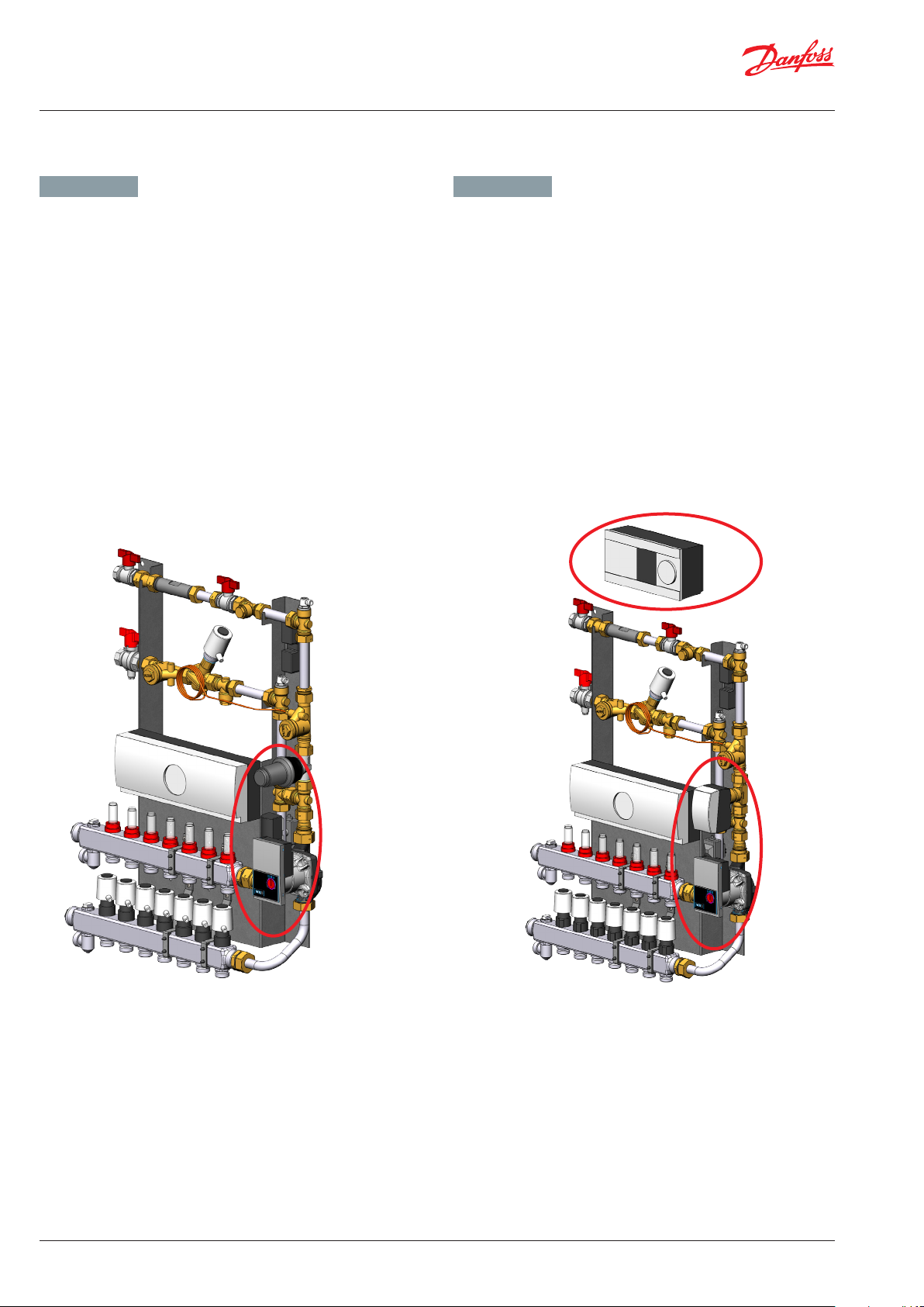
Mischkreis
Verteilersysteme SGTCM, SGTZCM und E-SGTZCM beeinhalten
einem Beimischkreis.
SGTCM und SGTZCM sind mit thermostatisch geregelten Mischk reis,
mit einer Umwälzpumpe, sowie einem FTC Thermostat zur regelung
der Vorlauftemperatur ausgestattet.
E-SGTZCM sind mit einem elektronisch geregelten Mischkreis mit
einer Umwalzpumpe, einem elektronischem Regler Typ ECL 310,
einem Stellantrieb Typ AMV 140 und einem VS2-Ventil zur Regelung
der Vorlauftemperatur ausgestattet.
Siehe bitte beigelegte Bedienungsanleitungen über Danfoss ECL
310 und Wilo Yonos Para Pumpe.
Mixing circuit
Distribution systems
integrated mixing circuit.
SCTCM and SGTZCM is supplied with a thermostatisch mixing circuit
with a circulation pump, as well as a FTC thermostat, which controls
the supply temperature.
E-SGTZCM is supplied with an electronic mixing circuit with a
circulation pump as well as a Danfoss electronic controller ECL 310,
which in combination with an actuator AMV 140 and VS2 valve controls
the supply temperature.
Please refer to enclosed instruction manuals for Danfoss ECL 310
and Wilo Yonos Para pump.
SGTCM, SGTZCM and E-SGTZCM
include an
145H0587, SGTZCM mit thermostatischem Mischkreis /
145H0587, SGTZCM with thermostatic mixing circuit
24 | © Danfoss | Produced by Danfoss Redan A/S | 2017.05
14 5H 06 07, E SGTZCM mit elektronischem Mischkreis /
145H0607, E-SGTZCM with electronic mixing circuit
VI.LZ.P1.5B
Page 25

Montageanleitung / Installation Guide Verteilersysteme / distribution units - Multifamily
11. REGELTECHNIK - FUSSBODENHEIZUNG / CONTROL - FLOOR HEATING
GERMAN - DE ENGLISH - GB
Thermostatische Regelung - FTC/RA-C
Die Vorlauftemperatur wird über ein Thermostat mit Anlege fühler,
Typ FTC, gemessen, der an der Vorlaufleitung angebracht ist.
In Verbindung mit einem 2-Wege-Ventil Typ RA-C wird die Temperatur der Fussbodenheizung geregelt.
Die Vorlauftemperatur wird über einen Anlegefühler gemessen,
der mit Hilfe der mitgelieferten Befestigung an der Rohrleitung
angebracht wird.
Der Schnappverschluss des Fühlerelementes sichert einen stabile
und sichere Montage am Ventilgehäuse.
Eigenschaften:
• Schließt bei steigenden Fühlertemperaturen
• Temperaturbereich 15-50°C (Fußbodenheizung)
• Gehäuse kann an der Vor- oder Rücklaufleitung
befestigt werden.
Siehe bitte beigelegte Bedienungsanleitung.
Fußbodenheizung:
Es ist überaus wichtig, daß die Vorlauftemperatur zu den Fussbodenheizkreis - unter Berücksichtigung des Komfortansprüche - so niedrig wie überhaupt möglich ist (ca. 30-35°.
Die Vorlauftemperatur soll nie 45°C überschreiten (IMMER die Instruktionen des Fussbodenlieferanten beachten).
Thermostatic control - FTC/RA-C
The supply temperature to the floor heating circuit is controlled
by the flow temperature controller FTC. The FTC is a self-acting
thermostatic sensor, which in combination with a 2-way valve body
type RA-N controls the the temperature for the floor heating circuit.
The water temperature is measured by a surface sensor, which is
easily mounted on the pipe with a strip (enclosed with the product).
The snap-lock connector of the sensor element secures a firm
connection to the valve.
Characteristics:
• Closes at rising sensor temperatures
• Temperature range 15-50° C (floor heating)
• Housing can be installed on the supply or return line
See enclosed instruction manual for further information.
Floor heating.
The supply temperature should typically be set to approx. 30–35°C,
which corresponds to pos. 2–2.5 on the thermostat (guiding value).
The supply temperature must never exceed 45°C. (In addition,
ALWAYS refer to the instructions from the floor supplier).
VI.LZ.P1.5B
Thermostat, Danfoss FTC
© Danfoss | Produced by Danfoss Redan A/S | 2017.05 | 25
Page 26

Montageanleitung / Installation Guide Verteilersysteme / distribution units - Multifamily
11. REGELTECHNIK - FUSSBODENHEIZUNG / CONTROL - FLOOR HEATING
Schaltdiagramm / Wiring diagram
26 | © Danfoss | Produced by Danfoss Redan A/S | 2017.05
VI.LZ.P1.5B
Page 27

Montageanleitung / Installation Guide Verteilersysteme / distribution units - Multifamily
© Danfoss | 2016.12
VI.KU.L4.9O | 1
AMV 130(H), AMV 140(H)
Operating Guide
11. REGELTECHNIK - FUSSBODENHEIZUNG / CONTROL - FLOOR HEATING
GERMAN
Elektronische Regelung - ECL
Für E-SGTZCM mit elektronischem Mischkreis wird die Temperatur für den Heizkreis elektronisch über eine Steuerung Danfoss
ECL 310, Applikation 230 gesteuert, in Kombination mit Stellantrieb AMV 140 und VS2 Ventil.
Die Vorlauftemperatur wird vom Regler in Abhängigkeit der Außentemperatur und der Heizkennlinie berechnet.
Mit hilfe eines ECL-Applikationssschlüssels (Plug- &-Play) kann eine ausgewählte Anwendung in den Regler ECL Comfort 210 geladen werden.
Der ECL-Applikationsschlüssel enthält Daten zu den Anwendungen
sowie Sprachen und Werkseinstellungen. Andere Anwendungen können aber mithilfe des ECL-Applikationsschlüssels geladen werden,
und Updates des Reglers sind mit neuer Anwendungssoftware auch
möglich.
Siehe bitte ECL Application Key Box mit ECL Comfort 210/310 Betriebsanleitung und Montageanleitung für weitere informationen.
Fußbodenheizung:
Es ist überaus wichtig, daß die Vorlauftemperatur zu den Fussbodenheizkreis
- unter Berücksichtigung des Komfortansprüche - so niedrig wie überhaupt
möglich ist (ca. 30-35°. Die Vorlauftemperatur soll nie 45° C überschreiten
(IMMER die Instruktionen des Fussbodenlieferanten beachten).
Stellantrieb + Ventil
Stationen mit Danfoss ECL Regler sind mit einem Durchgangsventil
VS 2 und einem elektrischen Stellantrieb Danfoss AMV 140, das dem
elektronischen Regler angeschlossen sind, ausgestattet.
ENGLISH
Electronic control - ECL
Für E-SGTZCM the temperature for the heating circuit is controlled
electronically by a Danfoss ECL 310 controller, application 230, in
combination with a AMV140 actuator and a VS2 valve.
The supply temperature ist calculated by the controller depending on
the outdoor temperature.
The ECL Comfort 310 controller is loaded with a selected application
by means of an ECL Application Key (Plug-&-Play). The Application Key
contains information about application, languages and factory settings.
Various applications can be loaded by means of the ECL Application Key,
and it is possible to update the controller with new application software.
The controller is factory preset to turn off the heating automatically in the
summer period. The controller settings can be changed in accordance with
the enclosed producer instructions for the mounted controller.
See ECL Application Key Box with ECL Comfort 210/310 user guide and
mounting guide, for further information.
Floor heating.
The supply temperature should typically be set to approx. 30–35°C, which
corresponds to pos. 2–2.5 on the thermostat (guiding value). The supply
temperature must never exceed 45° C. (In addition, ALWAYS refer to the
instructions from the floor supplier).
Actuator + valve
For stations fitted with a Danfoss ECL controller, an electronic actuator
AMV 140 and Danfoss 2-way valve VS2 will be fitted to the heating circuit.
AMV 140
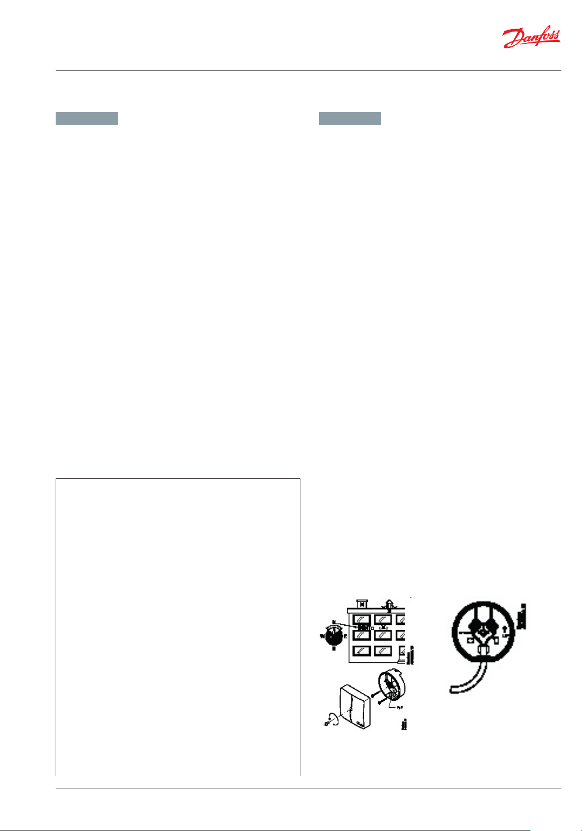
Der elektrische Stellantrieb ist werksseitig einer Funktionsprüfung
unterzogen worden. Bei Betriebsstörungen kann eine Handverstellung wie nachfolgend beschrieben durchgeführt werden.
1 Entferne die Abdeckung.
2 Stecke den Sechskantschlüssel in die Vorrichtung.
3 Drücke und halte den Knopf (auf der Unterseite
des Antriebs) während der Handverstellung
4 Ziehe das Werkzeug heraus.
5 Platziere die Abdeckung auf den Antrieb.
Achtung: Verstelle den Antrieb nicht unter Strom!
Anmerkung:
Ein ”klick” Geräusch nach der Inbetriebnahmedes
Antriebs bedeutet, dass das Getriebe in seine
normale Position gesprungen ist.
Für weitere information, siehe bitte beigelegte
Bedienungsanleitungen für AMV 13, VS2
AME 130, 140
AME 130H, 140H
ENGLISH
DANSK
DEUTSCH
NEDERLANDS
ITALIANO
MAGYAR
POLSKI
LIETUVIŲ K.
LATVISK I
РУССКИЙ
ČESKY
AMV + VZ 2 / VZL 2 AMV + VZ 3 / VZL 3 AMV + VZ 4 / VZL 4
Actuators for three point control
AMV 130, AMV 140, AMV 130H, AMV 140H
Motorer til 3-punkts styring
AMV 130, AMV 140, AMV 130H, AMV 140H
Stellantriebe für 3-Pkt.- Schmittsignall
AMV 130, AMV 140, AMV 130H, AMV 140H
Servomotoren met 3-puntssturing
AMV 130, AMV 140, AMV 130H, AMV 140H
Attuatore per il controllo a due punti
AMV 130, AMV 140, AMV 130H, AMV 140H
Szelepmozgatók hárompontos szabályozáshoz
AMV 130, AMV 140, AMV 130H, AMV 140H
Servopohony s tříbodovým regulačním signálem
AMV 130, AMV 140, AMV 130H, AMV 140H
Siłowniki sterowane sygnałem 3-punktowym
AMV 130, AMV 140, AMV 130H, AMV 140H
Pavaros trijų padėčių valdymui
AMV 130, AMV 140, AMV 130H, AMV 140H
Motori trīs punktu kontrolei
AMV 130, AMV 140, AMV 130H, AMV 140H
Электроприводы для аналогового регулирования
AMV 130, AMV 140, AMV 130H, AMV 140H
www.danfoss.com Page 4
www.danfoss.dk Page 5
www.danfoss.de Page 5
www.danfoss.nl Page 6
www.danfoss.com Page 6
www.danfoss.com Page 7
www.danfoss.cz Page 7
www.danfoss.pl Page 8
www.danfoss.lt Page 8
www.danfoss.com Page 9
www.danfoss.ru Page 9
AMV + AHQM
AMV 140
The electrical actuator has undergone a functional test from factory. In
case of operating disturbances manual override can be performed as
described below.
1 Remove the cover.
2 Insert the Allen key 6 into the spindle.
3 Press and hold the button (on the bottom side of the actuator) during manual
override.
4 Pull out the tool.
5 Place cover back on the actuator.
Caution: Do not manually operate the drive under power!
Remark:
A ”click” sound after energizing the actuator means that the
gear wheel has jumped into normal position.
For further information, see enclosed instructions for AMV 140, VS2
VI.LZ.P1.5B
© Danfoss | Produced by Danfoss Redan A/S | 2017.05 | 27
Page 28

Montageanleitung / Installation Guide Verteilersysteme / distribution units - Multifamily
1
Installation Guide
TWA-Z (Gen. 2011)
Heating Solutions VI.SB.I6.02 SMT/SI
TWA-Z & AB-QM
24 V Class III transformer (SELV)
230 V Max. 3 A pre-fuse
NO Normally Open
NC Normally Closed
NC
(Normally Closed)
IP 41
NO
Blue/Brown
NC
Blue/Brown
TWA-Z NO & AB-QM TWA-Z NC & AB-QM
11. REGELTECHNIK - FUSSBODENHEIZUNG / CONTROL - FLOOR HEATING
GERMAN - DE ENGLISH - GB
Sicherheitsthermostat / thermischer Stellantrieb TWA-Z
Bei Stationen für Fußbodenheizung ist der Heizkreis mit einem
Sicherheitsthermostat gegen Überhitzung ausgestattet. Bei Temperaturen über 55 °C schließt der Sicherheitsthermostat eines Ventil mittels eines thermischen Stellantriebes, Typ TWA-Z.
Der TWA-Z ist ein thermischer Stellantrieb zum Öffnen und
Schliessen von Ventilen.
Der Stellantrieb verfügt über eine Positionsanzeige für die Antriebsstange des Stellantriebs (siehe Abbildung).
Bei ausgefahrener Antriebsstange ist das Ventil geschlossen. Liegt
keine Kraft vom Stellantrieb an, öffnet die ventilinterne Feder das
Ventil.
Safety thermostat / thermal actuator TWA-Z
For protection against overheating the floor heating circuit can be
supplied with a safety thermostat. At temperatures above 55 °C the
safety thermostat and the thermal actuator TWA-Z, which is used
for ON/OFF controls of the heating system, will turn off the supply
flow to the heating circuit.
The actuator is equipped with a position indicator to show the position of the actuator stem (see below).
The valve is closed in stem down position.
Without actuator force the internal spring opens the valve.
Thermischer
Stellantrieb TWA-Z
28 | © Danfoss | Produced by Danfoss Redan A/S | 2017.05
VI.LZ.P1.5B
Page 29

Montageanleitung / Installation Guide Verteilersysteme / distribution units - Multifamily
Installation and operating instructions Wilo-Yonos PARA 02/12 4523676-01
Wilo-Yonos PARA
12. UMWÄLZPUMPE / CIRCULATION PUMP
GERMAN - DE ENGLISH - GB
Die Stationen SGCM, SGTZCM und E-SGTZCM sind mit Umwälzpumpe Wilo Yonos Para in dem Beimischkreis ausgestattet.
Die Bedienung der Pumpe erfolgt über den Bedienknopf. Durch
drehen des Knopfes können die unterschiedlichen Regelungsarten
ausgewählt und die Einstellung der Förderhöhe oder konstanten
Drehzahl vorgenommen werden.
Bei Systemen mit ECL Regler den roten Bedienknopf nach rechts
drehen (Differenzdruck konstant) und anfänglich auf “Max. Pos. “.
Stellen Sie dann die Pumpe in Abhängigkeit vom Heizbedarf des
Gebäudes auf die niedrigstmögliche Position - unter Berücksichtigung von Aspekten wie Kühlung und Leistungsaufnahme.
Entlüften:
Entlüften Sie das System mit den Entlüftungsventilen in der Station.
Die Pumpe verfügt auch über eine eingebaute Entlüftungsfunktion,
die verwendet werden kann, wenn das System entlüftet werden
muss.
Durch Drehen des Bedienknopfes in die Mittelstellung, auf das
Symbol für die Entlüftung, wird nach 3 Sekunden die Entlüftungsfunktion aktiviert. Die Dauer der Entlüftungsfunktion beträgt 10
Minuten und wird durch schnelles grünes Blinken der LED angezeigt. Während der Entlüftungsfunktion kann es zu Geräuschbildung
kommen. Der
Vorgangt kann auf Wunsch durch Drehen des Knopfes abgebrochen
werden.
Nach Ablauf der 10 Minuten stoppt die Pumpe und geht automatisch in die Regelungsart Differenzdruck Konstant max.
The stations SGCM, SGTZCM and E-SGTZCM are supplied with Wilo
Yonos Para circulation pump in the mixing circuit.
The pump is operated via the red control switch. By turning the knob,
different control modes can be selected and the setting of the discharge height or constant speed can be made.
On systems with ECL controller turn the red switch to the right (constant
differential pressure) and set it to “Max. pos.” initially. Then set the pump
to the lowest possible position, depending on the heating requirement
for the building - taking into account aspects such as cooling and power
consumption.
Venting:
Vent the system by using the vent valves in the unit.
The pump also features a built-in venting function, which can be
used when the system needs to be bled.
Turn the red switch to the vertical position. The pump will then run a
venting routine that lasts 10 minutes. There may be some noise during this phase. Once the 10-minute period is finished, reset the pump
according to the instructions above.
By turning the Red Knob to the symbol for venting in the middle position, the venting function is activated after 3 seconds. The venting
function lasts 10 minutes and is indicated wit quick green LED blinking. Noises may be heard during the venting function is running. The
process can be stopped if desired by turning the Red Knob.
After 10 minutes, the pump stops and goes automatically in Delta PC
max mode.
Danach muss die Regelungsart und die Förderhöhe ingestellt
werden, falls die Pumpe nicht bei ∆p-c max. weiter betrieben
werden soll.
Für weitere Informationen über Entlüftung der Pumpe u.s.w. sehen
Sie bitte beigelegtes Bedienerhandbuch:
WILO Yonos Para Einbau- und Betriebsanleitung
Afterwards, the control mode and the delivery head must be set if
not the pump will operate in Delta Pc max mode.
For additional information, see the enclosed manual:
Wilo Yonos PARA.
1 General
About this document
The language of the original operating instructions is English. All
other languages of these instructions are translations of theoriginal
operating instructions.These installation and operating instructions
are an integral part of the product. They must be kept readily
available at the place where the product is installed. Strict
adherence to theseinstructions is a precondition for the proper use
and correctoperation of the product.
The installation and operating instructions correspond to the
relevant version of the product and the underlying safety regulations
and standards valid at the time of going to print.EC declaration of
conformity:
A copy of the EC declaration of conformity is a component ofthese
operating instructions(f ig 8). If a technical modification is made on
the designs named therewithout our agreement or the declarations
made in the installation and operating instructions on
product/personnel safety
are not observed, this declaration loses its validity.
2 Safety
These operating instructions contain basic information which must
be adhered to during installation, operation and maintenance.
For this reason, these operating instructions must, without fail, be
read by the service technician and the responsible
specialist/operator before installation and operation.
It is not only the general safety instructions listed under the main
point “safety” that must be adhered to but also the special safety
instructions with danger symbols included under the following main
points.
DIfferenzdruck konstant
max. (∆p-c) /
Constant differential pres-
sure Max. pos.
Differenzdruck variabel
max. (∆p-v) /
Variable differential
pressure
Max. pos.
The new standard in High Efficiency
GB:Installation and operating instructions Wilo-Yonos PARA
Entlüftungsfunktion /
Venting Vertical pos.
VI.LZ.P1.5B
© Danfoss | Produced by Danfoss Redan A/S | 2017.05 | 29
Page 30

Montageanleitung / Installation Guide Verteilersysteme / distribution units - Multifamily
13. Wartung / Maintenance
GERMAN - DE ENGLISH - GB
Wartungsarbeiten
Sind nur von qualifizierten und autorisierten Personen durchzuführen.
Überprüfung
Es unterliegt es der sorgfaltspflicht der Betrieber, in regelmäßigen
Abständen Inspektionen und wenn nötig Instandhaltungsarbeiten
laut dieser und anderen Anleitungen durchführen zu lassen. Im
Rahmen der o. g. Wartungsarbeiten sind alle Schmutzfänger zu
reinigen, alle Verschraubungen und Verbindungen nachzuspannen und die Sicherheitsventile durch Drehen des Handgriffes in
die markierte Richtung zu überprüfen.
Maßnahmen nach Wartungsarbeiten
Nach den Wartungsarbeiten und vor dem Einschalten der Anlage:
– Alle gelösten Schraubenverbindungen auf festen Sitz überprüfen.
– Überprüfen, ob alle zuvor entfernten Schutzvorrichtungen,
Abdeckungen wieder ordnungsgemäß eingebaut sind.
– Arbeitsbereich säubern und evtl. ausgetretene Stoffe entfernen.
– Alle verwendeten Werkzeuge, Materialien und sonstige
Ausrüstungen aus dem Arbeitsbereich wieder entfernen.
– Energieversorgung einschalten und von Leckagen überwachen.
– Anlage entlüften.
– Wenn nötig die Anlage neu einstellen.
– Sicherstellen, dass alle Sicherheitseinrichtungen des Gerätes
und der Anlage wieder einwandfrei funktionieren.
Maintenance work
Is only to be carried out by qualified and authorised personnel.
Inspection
The water heater should be checked regularly by authorised person-
nel. Any necessary maintenance must be performed in accordance
with the instructions in this manual and other sets of instructions.
During service the dirt strainers are to be cleaned – including the
filter on the controller, all pipe connections must be tightened and
the safety valve must be function tested by turning the lever.
Measures after maintenance work
After maintenance work and before commissioning:
– Check that all screwed connections are tight.
– Check that all safety features, covers, that were removed, have
been replaced properly.
– Clean the working area and remove any spilled materials.
– Clear all tools, materials and other equipment from the working
area.
– Connect to energy supply and check for leaks.
– Vent the system.
– Carry out any necessary adjustment again.
– Make sure that all safety features on the device and the system
work properly.
30 | © Danfoss | Produced by Danfoss Redan A/S | 2017.05
VI.LZ.P1.5B
Page 31

Montageanleitung / Installation Guide Verteilersysteme / distribution units - Multifamily
14. EU GUTACHTEN / EU DECLARATION OF CONFORMITY
VI.LZ.P1.5B
© Danfoss | Produced by Danfoss Redan A/S | 2017.05 | 31
Page 32

Montageanleitung / Installation Guide Verteilersysteme / distribution units - Multifamily
15. INBETRIEBNAHMEZERTIFIKAT
Die Station ist die direkte Verbindung zwischen der Wärmeversorgung und der Hausinstallation.
Vor der Inbetriebnahme der Wohnungsstation ist die übrige Anlage gründlich zu spülen und die Dichtheit der Verbindungen ist zu überprüfen. Sobald das System mit Wasser gefüllt worden ist, müssen alle Rohrverbindungen, bevor Druckprobe auf Dichtheit, nachgezogen
werden. Die Schmutzfänger reinigen und die Einstellungen gemäss der Hinweise dieser Betriebsanleitung durchführen.
Beim Einbau sind alle örtlichen Standards und Vorschriften einzuhalten.
Installation und erste Inbetriebnahme dürfen nur von qualifizierten und autorisierten Personen durchgeführt werden.
Die Station ist in der Fabrik auf Dichtigkeit vor der Auslieferung geprüft worden, aber nach Transport, Handhabung und Aufheizen der Anlage
sind sämtliche Verschraubungen und Anschlusse zu kontrollieren und gegebenenfalls nachzuziehen. Bitte beachten Sie, dass die Verbindungen mit EPDM Gummidichtungen ausgeführt werden können. Deshalb ist es sehr wichtig die Überwurfmutter nicht zu überspannen,
da dies zu Undichtigkeiten führen kann. Der Hersteller übernimmt keine Haftung für Leckagen, die aus Überspannung zurückzuführen sind.
Diese Anlage wurde nachgezogen, angepasst und in Betrieb genommen
den:
von Installateur:
Datum/Jahre
Firmenname (Stempel)
32 | © Danfoss | Produced by Danfoss Redan A/S | 2017.05
VI.LZ.P1.5B
Page 33

Montageanleitung / Installation Guide Verteilersysteme / distribution units - Multifamily
15. COMMISSIONING CERTIFICATE
The unit is the direct link between the heating supply network and the household piping system. All supply pipes and the pipes in
the household piping system must be checked and rinsed before commissioning. Once the system has been filled with water, all pipe
connections
must be retightened before performing pressure test for leaks. The dirt strainers must be cleaned and the unit must be adjusted
in accordance with the instructions in this manual.
It is important to comply with all technical regulations and the applicable legislation in every respect.
Installation and commissioning must only be performed by trained, authorised personnel.
The unit is checked in the factory for leaks before delivery. Leaks are however possible due to vibrations caused by transport, hand-ling and
heating of the system and therefore it is important to check all connections and to retighten if necessarys before commissioning.
Please note that the connections may feature EPDM gaskets! Therefore it is important that you DO NOT OVER-TIGHTEN the connections.
Over-tightening may result in leaks. Leaks caused by ove-rtightening or failure to retighten connections are not covered by the warranty.
This unit has been retightened, adjusted and commissioned
on the:
by installer:
Date/Year
Company name (stamp)
VI.LZ.P1.5B
© Danfoss | Produced by Danfoss Redan A/S | 2017.05 | 33
Page 34

Montageanleitung / Installation Guide Verteilersysteme / distribution units - Multifamily
34 | © Danfoss | Produced by Danfoss Redan A/S | 2017.05
VI.LZ.P1.5B
Page 35

Montageanleitung / Installation Guide Verteilersysteme / distribution units - Multifamily
VI.LZ.P1.5B
© Danfoss | Produced by Danfoss Redan A/S | 2017.05 | 35
Page 36

Die in
Anw
oder
bereits in A
Danf
Danfoss GmbH, Heating Segment,
Te
l.: + 49 (0)69 97 53 30 44, CS@danfoss.de, www.heating.danfoss.de
Danfoss A
Te
Danfoss Ges.m.b
T
Carl-Legien-Straße 8, D-63073 Offenbach, Deutschland
G, Parkstraße 6, CH-4402 Frenkendorf, Schweiz
l.: +41 (0)61 510 00 19, CS@danfoss.ch, www.danfoss.ch
el: +43 (0)1 253 022 322, CS@danfoss.at, www.heating.danfoss.at
Katalogen, Prospekten und anderen schriftlichen Unterlagen, wie z.B. Zeichnungen und Vorschlägen enthaltenen Angaben und technischen Daten sind vom Käufer vor Übernahme und
endung zu prüfen. Der Käufer kann aus diesen Unterlagen und zusätzlichen Diensten keinerlei Ansprüche gegenüber Danfoss oder Danfoss Mitarbeitern ableiten, es sei denn, dass diese vorsätzlich
grob fahrlässig gehandelt haben. Danfoss behält sich das Recht vor, ohne vorherige Bekanntmachung im Rahmen des Angemessenen und Zumutbaren Änderungen an ihren Produkten – auch an
oss A/S. Alle Rechte vorbehalten.
36 | © Danfoss | Produced by Danfoss Redan A/S | 2017.05
.H., Heating Segment, Danfoss Straße 8, A-2353 Guntramsdorf, Österreich
uftrag genommenen – vorzunehmen.
Alle in dieser Publikation enthaltenen Warenzeichen sind Eigentum der jeweiligen Firmen. Danfoss und das Danfoss Logo sind Warenzeichen der
VI.LZ.P1.5B
 Loading...