

Page 1
Data Sheet
Safety relief valve
Type SFV 20-25
Designed for protection of vessels and other components
against excessive pressure
SFV 20 - 25 are standard, back pressure
dependent safety relief valves in angle-way
execution, specially designed for protection of
vessels and other components against
excessive pressure.
The valve is designed to meet the strict quality
demands and safety requirements for
refrigeration installations, specied by the
international classication societies.
The valve is recommended as an external and
internal safety relief valve in refrigeration
plants. The spring housing is closed tightly to
avoid refrigerant leakage.
The inlet ow diameters of the valves are:
• 18 mm (
• 23 mm (1 in.) for SFV 25
The valves can be delivered with set pressures
between 10 and 25 bar (145 and 363 psig).
Standard pressure setting valves having "TÜV
Pressure Setting Certicate" with each valve,
are also available.
Features
• Applicable for the refrigerants HCFC, HFC,
R717 (Ammonia), R744 (CO2) within a
temperature range of –30°C / +100°C (–22°F /
+212°F).
• Classication: DNV, CRN, BV, EAC etc. To get
an updated list of certication on the
products please contact your local Danfoss
Sales Company.
3
⁄4 in.) for SFV 20
AI175286423559en-000701
Page 2
Safety relief valve, Type SFV 20-25
Media
Refrigerants
Applicable for the refrigerants HCFC, HFC, R717 (Ammonia), R744 (CO2) within a temperature range of -30 °C/+100
°C (-22 °F/+212 °F)
• Flammable hydrocarbons are not recommended.
• For further information please contact your local Danfoss Sales Company.
New refrigerants
Danfoss products are continually evaluated for use with new refrigerants depending on market requirements.
When a refrigerant is approved for use by Danfoss, it is added to the relevant portfolio, and the R number of the
refrigerant (e.g. R513A) will be added to the technical data of the code number. Therefore, products for specic
refrigerants are best checked at store.danfoss.com/en/, or by contacting your local Danfoss representative.
© Danfoss | Climate Solutions | 2021.02 AI175286423559en-000701 | 2
Page 3
The SFV-valves are approved in accordance with the European standard
specied in the Pressure Equipment Directive and are CE
marked. For further details / restrictions - see Installation Instruction.
SFV valves
Nominal bore
18 mm (0.709 in.)
23 mm (0.906 in.)
Classied
for
Fluid group I
Category
IV
Safety relief valve, Type SFV 20-25
Product specication
Pressure and temperature data
• Pressure
Pressure setting range: 10 - 25 bar (145 - 363 psig). For further information please contact your local Danfoss Sales
Company.
The valves are designed for: Strength test:
◦ 43 bar (624 psig)
• Leakage safety
Same as set pressure.
IMPORTANT:
The SFV safety relief valve is dependent on the back pressure (if the back pressure is higher than the atmospheric
pressure, the opening pressure will be higher than stated set pressure).
Special circumstances such as vibrations (which should be avoided) and oscillating pressure may require an
increased dierence between the operational pressure and the closing pressure.
• Pressure setting
The operating pressure of the plant should be at least 15% below the set pressure. This allows a perfect re-seating
of the safety relief valve after having been activated.
• Temperature range : –30 °C/+100 °C (–22/+212 °F)
Design
Housing
Made of special steel approved for low temperature operation. Spindle and seat are made of stainless steel, to
ensure precise operation even during extraordinary conditions. The gasket of the valve cone is made of a special
chloroprene (neoprene) rubber.
Re-calibration/servicing
In certain countries the authorities demand that the valves are checked at least once a year (see local rules).
Control/Identication
After adjustment of the set pressure at Danfoss, the valves are sealed. For that reason Danfoss can only guarantee
correct operation, as long as the seal remains unbroken.
All valves are provided with a metal plate with the following information:
• Flow diameter
• Set pressure
• Date of production
• Production number
• Type approved code
Transport/Handling
The valves are tted with special protection covers and packed into purpose made transportation cartons.
It is important the cover remains tted around the valve until it is installed.
To ensure the exact and precise operation of the valve it must be handled with care.
Pressure Equipment Directive (PED)
Table 1: Pressure Equipment Directive (PED)
Table 2: SFV
© Danfoss | Climate Solutions | 2021.02 AI175286423559en-000701 | 3
Page 4
Working pressure
Reseating pressure
Set pressure p
Opening pressure
p + 10%
p – 10%
0 100% Opening degree
Size (mm)
Size (in.)
Inlet
Outlet
L (mm)
L (in.)
2025¾1G 1¼
G 1¼
G 1½
G 1½2020
0.79
0.79
ø
Size (mm)
Size (in)
Inlet (mm)
Inlet (in.)
Outlet (mm)
Outlet (in.)
øDTøDTøDTøD
T
20
25
3
⁄4
1
26.9
2.6
2.3251.059
1.327
0.091
0.102
33.7
42.4
2.6
2.6
1.337
1.669
0.102
0.102
Safety relief valve, Type SFV 20-25
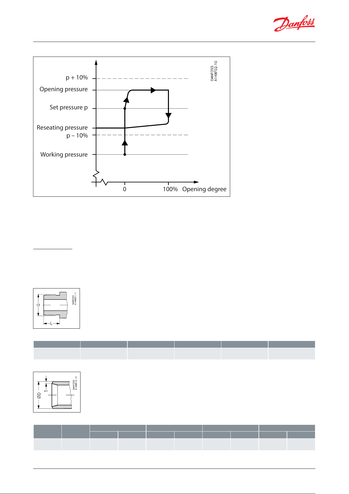
Figure 1: SFV Graph
SFV is designed as a standard safety relief valve (DIN 3320), which are recommended for refrigeration plants. On a
rise in pressure above the set pressure, the safety relief valve will initially start opening slightly, to minimise the
outlet of refrigerant. If the pressure continues to increase, the valve will open fully. The safety relief valve will be fully
open before the pressure is 10% higher than set pressure, and fully closed before the pressure is 10% below set
pressure.
Connections
Available with the following connections:
• Outside pipe thread T (ISO 228/1)
• Welding ttings (DIN 2448)
Figure 2: T
Table 3: T outside pipe thread, (ISO 228/1)
Figure 3: DIN
Table 4: Welding ttings DIN (2448)
© Danfoss | Climate Solutions | 2021.02 AI175286423559en-000701 | 4
Page 5
q
m
C
A0K
dr
K
b
V
pset
p
atm
p
Valve
Nominal size
Flow diameter
Flow area
De-rated, certied coecient of discharge
Inlet
Outlet
doA
0
K
dr
SFV 20
20 mm
25 mm
18 mm
254 mm
2
0.54
¾ in.
1 in.
0.709 in.
0.394 in
2
SFV 25
25 mm
32 mm
23 mm
415 mm
2
0.48
1 in.1¼0.906 in.
0.643 in
2
Discharge capacity (kg/h)
Discharge function depending of the actual refrigerant (κ) see table 2 (‑)
Flow area of the safety relief valve (mm2).
De-rated coecient of discharge (Kdr = Kd × 0.9), (the Kdr is certied by TÜV) see table 1 (‑)
Correction factor for sub‑critical ow. (-) Kb = 1.0 when the back pressure is lower than approx. 0.5 × relieving
pressure (Pb < 0.5 × p) For all SFV safety valves Kb = 1.0
Specic volume of the vapour at the releiving pressure p. (m3/kg)
Set pressure, the predetermined pressure at which a pressure relief valve under operation starts to open (p
set
is indicated on the metal plate on the safety relief valve). (bar gauge)
Atmospheric pressure. (1 bar)
Relieving pressure, p = pset × 1.1 + Patm (bar absolute)
Refrigerant
Isentropic exponent κ
Discharge function C
R22
1.17
2.54
R134a
1.12
2.5
R404A
1.12
2.49
Safety relief valve, Type SFV 20-25
Installation
To ensure exact operation of the safety relief valve it should be installed with the spring housing upwards. If the
valve is mounted as an internal safety relief valve without any demand for exact opening pressure, the valve may be
tted with the spring housing in other positions. When the valve is mounted, it is important to avoid the inuence
of static, dynamic and thermal stress.
A very precise technique has been applied for the production of the seal. However, this seal can still be damaged, if
dirt is blown from the pipe system into the valve.
It is recommended that safety relief valves exhaust into the open air with a U‑pipe lled with oil on the discharge
branch, to prevent dirt from penetrating into the valve. It is also recommended that the valves be installed in pairs
in conjunction with the double stop valve type DSV. For further information please see the DSV data sheet.
Capacity
The design and construction of the safety relief valve has been tested and approved by TÜV. This test comprises
control of the function of the valve as well as measuring of the capacity, which is the basis of the curves and tables
on the following pages. The values in the table are based on saturated gas.
If e.g. back pressure or superheated gas have to be taken into consideration, the formulas or the Danfoss
computation program (DIRcalc) can be used.
Table 5: Capacity Values
The discharge capacity of the safety relief valves are based on (IS0 4126‑1 / prEN 1313 6 (1998)).
qm= 0.2883 × C × A0× Kdr× K
p
b
v
For further details see the above-mentioned ISO or EN standards.
Table 6: Table 2. Properties of Refrigerants
© Danfoss | Climate Solutions | 2021.02 AI175286423559en-000701 | 5
Page 6

Refrigerant
Isentropic exponent κ
Discharge function C
R410A
1.17
2.54
R717 (Ammonia)
1.31
2.64
R744 (CO2)
1.3
2.63
Air
1.4
2.7
Set pressure
R22
R134a
R404A
R717
Air (20 °C)
13 bar(g)
189 psig
kg/h
lb/min
3220
118
3430
126
3500
129
1415521790
66
18 bar(g)
261 psig
kg/h
lb/min
4440
163
4800
176
4900
180
1925712435
89
21 bar(g)
305 psig
kg/h
lb/min
5215
192
5680
209
5770
212
2235822820
104
25 bar(g)
363 psig
kg/h
lb/min
6285
231
6980
257
7125
262
2660983335
122
Set pressure
Capacity
R717
R404A
R134a
Air (20°C)
R22R22
(
(
Danfoss
80Z814
Set pressure
R22
R134a
R404A
R717
Air (20 °C)
13 bar(g)
189 psig
kg/h
lb/min
4670
172
4980
183
5075
186
2050752600
96
18 bar(g)
261 psig
kg/h
lb/min
6445
237
6965
256
7115
261
2790
103
3530
130
21 bar(g)
305 psig
kg/h
lb/min
7565
278
8240
303
8370
308
3240
119
4090
150
25 bar(g)
363 psig
kg/h
lb/min
9120
335
10135
372
10340
380
3860
142
4835
178
Safety relief valve, Type SFV 20-25
Table 7: Capacity : SFV 20
Figure 4: SFV 20
Table 8: Capacity : SFV 25
© Danfoss | Climate Solutions | 2021.02 AI175286423559en-000701 | 6
Page 7

(
(
Set pressure
Capacity
Danfoss
80Z815
Safety relief valve, Type SFV 20-25
Figure 5: SFV 25
Material specication
Figure 6: Material specication
© Danfoss | Climate Solutions | 2021.02 AI175286423559en-000701 | 7
Page 8

No.
Part
Material
DIN
ISO
ASTM
1
Housing
Steel
G20Mn5 QT
*P285QH
*TTSt35N
TW 6, 2604/3‑75
Grade 1, A333, A334
* A350 LF2
2
Valve seat
Stainless steel
X10CrNiS189, 17440
Type 17, 683/13
AISI 303
3
Packing washer
Aluminium
*Non-asbestos gasket
4
Valve top
Steel
St. 37.2, 1652
Fe 360 B, 660
Grade C, A 283
6
Valve spindle
Stainless steel
X10CrNiS189, 17440
Type 17, 683/13
AISI 303
10
Valve cone
Steel
11
Valve cone seal
Chloroprene (Neoprene)
15
Packing washer
Aluminium
*Non-asbestos gasket
17
Spring
Steel
Class C
A 679, 17223
23
Packing washer
Aluminium
*Non-asbestos gasket
24
Plug
Steel
9S Mn28, 1651
*R St 37.2, 17100
Type 2, R 683 Fe 360 B,
630
Grade C, A 283
25
Marking label
Aluminium
SFV 20 - 25 T
SFV 20 - 25 with welding ttings (anges)
G₀
øD
AF
G₁
A
B
Valve size
ABCøDAF
Weight
SFV 20 (
3
⁄4 in.)
mm152704060604.2 kg
in.
2.17
10.63
1.57
2.36
2.36
9.2 lb
SFV 25 (1 in.)
mm552704060604.2 kg
in.
2.17
10.63
1.57
2.36
2.36
9.2 lb
Safety relief valve, Type SFV 20-25
Table 9: Specications
*Alternative material
Dimension and weight
Table 10: Dimension and weight
Table 11: SFV 20 - 25 T, with threaded connections ISO 228/1 pipe threads
© Danfoss | Climate Solutions | 2021.02 AI175286423559en-000701 | 8
Page 9

Valve size
A
B
G
0
øD
G
1
AF
Weight
SFV 20 (
3
⁄4 in.)
mm8530090609060
4.2 kg
in.
3.35
11.81
3.54
2.36
3.54
2.36
9.2 lb
SFV 25 (1 in.)
mm8530090609060
6.0 kg
in.
3.35
11.81
3.54
2.36
3.54
2.36
13.2 lb
Safety relief valve, Type SFV 20-25
Table 12: SFV with welding ttings, DIN 2448
Specied weights are approximate values only.
© Danfoss | Climate Solutions | 2021.02 AI175286423559en-000701 | 9
Page 10

Valve type
SFV
Safety relief valve
Available connections
T
DIN welding tting
Nominal size in mm (valve
size measured on the
connection diameter)
20
DN 20××
25
DN 25××
Connections
T
Outside threaded connections: ISO 228/1 Pipe thread
- The welding ttings for single mounted safety relief valve must be ordered separately
Pressure setting
Standard pressure setting: 2××
SFV 20
SFV 25
210
10 bar (145 psig)
××211
11 bar (160 psig)
××212
12 bar (174 psig)
××213
13 bar (188 psig)
××214
14 bar (203 psig)
××215
15 bar (218 psig)
××216
16 bar (232 psig)
××217
17 bar (247 psig)
××218
18 bar (261 psig)
××219
19 bar (276 psig)
××220
20 bar (290 psig)
××221
21 bar (305 psig)
××222
22 bar (319 psig)
××223
23 bar (334 psig)
××224
24 bar (348 psig)
××225
25 bar (363 psig)
××Standard pressure setting with TÜV certicate: 3××
SFV 20
SFV 25
310
10 bar (145 psig)
××311
11 bar (160 psig)
××312
12 bar (174 psig)
××313
13 bar (188 psig)
××314
14 bar (203 psig)
××315
15 bar (218 psig)
××316
16 bar (232 psig)
××317
17 bar (247 psig)
××318
18 bar (261 psig)
××319
19 bar (276 psig)
××320
20 bar (290 psig)
××321
21 bar (304 psig)
××322
22 bar (319 psig)
××323
23 bar (334 psig)
××324
24 bar (348 psig)
××325
25 bar (362 psig)
×
×
Safety relief valve, Type SFV 20-25
Ordering
How to order
The table below is used to identify the valve required. Please note that the type codes only serve to identify the
valves, some of which may not form part of the standard product range. For further information please contact your
local Danfoss Sales Company.
Example for type codes
Table 13: SFV 20 T 210
WARNING:
Where products need to be certied according to specic certication societies, the relevant information should be
included at the time of order.
© Danfoss | Climate Solutions | 2021.02 AI175286423559en-000701 | 10
Page 11

Size
Construction and test facilities are approved by TUV
mm
in.
Type
Bar (psig)
Part no.
20
3
⁄4
SFV20 T 210
10 (145)
2416+254
20
3
⁄4
SFV20 T 211
11 (160)
2416+255
20
3
⁄4
SFV20 T 212
12 (174)
2416+256
20
3
⁄4
SFV20 T 213
13 (189)
2416+150
20
3
⁄4
SFV20 T 214
14 (203)
2416+257
20
3
⁄4
SFV20 T 215
15 (218)
2416+258
20
3
⁄4
SFV20 T 216
16 (232)
2416+259
20
3
⁄4
SFV20 T 217
17 (247)
2416+260
20
3
⁄4
SFV20 T 218
18 (261)
2416+151
20
3
⁄4
SFV20 T 219
19 (276)
2416+261
20
3
⁄4
SFV20 T 220
20 (290)
2416+262
20
3
⁄4
SFV20 T 221
21 (305)
2416+152
20
3
⁄4
SFV20 T 222
22 (319)
2416+241
20
3
⁄4
SFV20 T 223
23 (334)
2416+263
20
3
⁄4
SFV20 T 224
24 (348)
2416+264
20
3
⁄4
SFV20 T 225
25 (363)
2416+183
Size
Construction and test facilities are approved by TUV
mm
in.
Type
Bar (psig)
Part no.
25
1
SFV25 T 210
10 (145)
2416+265251
SFV25 T 211
11 (160)
2416+266251
SFV25 T 212
12 (174)
2416+267251
SFV25 T 213
13 (189)
2416+153251
SFV25 T 214
14 (203)
2416+268251
SFV25 T 215
15 (218)
2416+269251
SFV25 T 216
16 (232)
2416+270251
SFV25 T 217
17 (247)
2416+271251
SFV25 T 218
18 (261)
2416+154251
SFV25 T 219
19 (276)
2416+272251
SFV25 T 220
20 (290)
2416+273251
SFV25 T 221
21 (305)
2416+155251
SFV25 T 222
22 (319)
2416+242251
SFV25 T 223
23 (334)
2416+274251
SFV25 T 224
24 (348)
2416+275251
SFV25 T 225
25 (363)
2416+184
Size
Each valve is certied by a representative from TUV
mm
in.
Type
Bar (psig)
Part no.
20
3
⁄4
SFV20 T 310
10 (145)
2416+285
20
3
⁄4
SFV20 T 311
11 (160)
2416+286
20
3
⁄4
SFV20 T 312
12 (174)
2416+287
20
3
⁄4
SFV20 T 313
13 (189)
2416+160
20
3
⁄4
SFV20 T 314
14 (203)
2416+288
20
3
⁄4
SFV20 T 315
15 (218)
2416+289
20
3
⁄4
SFV20 T 316
16 (232)
2416+290
20
3
⁄4
SFV20 T 317
17 (247)
2416+291
20
3
⁄4
SFV20 T 318
18 (261)
2416+161
20
3
⁄4
SFV20 T 319
19 (276)
2416+292
20
3
⁄4
SFV20 T 320
20 (290)
2416+293
20
3
⁄4
SFV20 T 321
21 (305)
2416+162
20
3
⁄4
SFV20 T 322
22 (319)
2416+294
20
3
⁄4
SFV20 T 323
23 (334)
2416+295
20
3
⁄4
SFV20 T 324
24 (348)
2416+296
20
3
⁄4
SFV20 T 325
25 (363)
2416+186
Safety relief valve, Type SFV 20-25
Table 14: Certied SFV valves with standard set pressure
Table 15: Certied SFV valves with standard set pressure
Table 16: Certied SFV valves with standard set pressure and TUV pressure setting certicate with each valve
© Danfoss | Climate Solutions | 2021.02 AI175286423559en-000701 | 11
Page 12

Size
Each valve is certied by a representative from TUV
mm
in.
Type
Bar (psig)
Part no.
25
1
SFV25 T 310
10 (145)
2416+297251
SFV25 T 311
11 (160)
2416+298251
SFV25 T 312
12 (174)
2416+299251
SFV25 T 313
13 (189)
2416+163251
SFV25 T 314
14 (203)
2416+300251
SFV25 T 315
15 (218)
2416+301251
SFV25 T 316
16 (232)
2416+302251
SFV25 T 317
17 (247)
2416+303251
SFV25 T 318
18 (261)
2416+164251
SFV25 T 319
19 (276)
2416+304251
SFV25 T 320
20 (290)
2416+305251
SFV25 T 321
21 (305)
2416+165251
SFV25 T 322
22 (319)
2416+306251
SFV25 T 323
23 (334)
2416+307251
SFV25 T 324
24 (348)
2416+308251
SFV25 T 325
25 (363)
2416+187
Type
Code No.
Flanges + gaskets set for SFV 20
148F3020
Flanges + gaskets set for SFV 25
148F3021
Type
Code No.
Repair kit for SFV 20 (gaskets and cone)
2453+082
Repair kit for SFV 25 (gaskets and cone)
2453+083
Safety relief valve, Type SFV 20-25
Table 17: Certied SFV valves with standard set pressure and TUV pressure setting certicate with each valve
Table 18: Flanges and gaskets
Table 19: Repair kit
© Danfoss | Climate Solutions | 2021.02 AI175286423559en-000701 | 12
Page 13

File name
Document type
Document topic
Approval authority
BV 39409-B0 BV
Marine - Safety Certicate
BV
Kolding - Denmark; Tianjin - China
TUV 07 202 1321 Z 0018-13-D-01
Pressure - Safety Certicate
PED
TÜV
TUV SV 17-895
Pressure - Safety Certicate
TÜV
DNV GL TAP000000M
Marine - Safety Certicate
DNV GL
RMRS 19.10327.266
Marine - Safety Certicate
RMRS
Safety relief valve, Type SFV 20-25
Certicates, declarations and approvals
The list contains all certicates, declarations, and approvals for this product type. Individual code number may have
some or all of these approvals, and certain local approvals may not appear on the list.
Some approvals may change over time. You can check the most current status at danfoss.com or contact your local
Danfoss representative if you have any questions.
Valid approvals
Table 20: Valid approvals
© Danfoss | Climate Solutions | 2021.02 AI175286423559en-000701 | 13
Page 14

Online support
Danfoss oers a wide range of support along with our products, including digital product information, software,
mobile apps, and expert guidance. See the possibilities below.
The Danfoss Product Store
The Danfoss Product Store is your one-stop shop for everything product related—no matter where
you are in the world or what area of the cooling industry you work in. Get quick access to essential
information like product specs, code numbers, technical documentation, certications, accessories,
and more.
Start browsing at store.danfoss.com.
Find technical documentation
Find the technical documentation you need to get your project up and running. Get direct access to
our ocial collection of data sheets, certicates and declarations, manuals and guides, 3D models
and drawings, case stories, brochures, and much more.
Start searching now at www.danfoss.com/en/service-and-support/documentation.
Danfoss Learning
Danfoss Learning is a free online learning platform. It features courses and materials specically
designed to help engineers, installers, service technicians, and wholesalers better understand the
products, applications, industry topics, and trends that will help you do your job better.
Create your Danfoss Learning account for free at www.danfoss.com/en/service-and-support/learning.
Get local information and support
Local Danfoss websites are the main sources for help and information about our company and
products. Find product availability, get the latest regional news, or connect with a nearby expert—all
in your own language.
Find your local Danfoss website here: www.danfoss.com/en/choose-region.
Spare Parts
Get access to the Danfoss spare parts and service kit catalog right from your smartphone. The app
contains a wide range of components for air conditioning and refrigeration applications, such as
valves, strainers, pressure switches, and sensors.
Download the Spare Parts app for free at www.danfoss.com/en/service-and-support/downloads.
Coolselector®2 - nd the best components for you HVAC/R system
Coolselector®2 makes it easy for engineers, consultants, and designers to nd and order the best
components for refrigeration and air conditioning systems. Run calculations based on your operating
conditions and then choose the best setup for your system design.
Download Coolselector®2 for free at coolselector.danfoss.com.
Danfoss can accept no responsibility for possible errors in catalogues, brochures and other printed material. Danfoss reserves the right to alter its
products without notice. This also applies to products already on order provided that such alterations can be made without subsequential
changes being necessary in specications already agreed. All trademarks in this material are property of the respective companies. Danfoss and
the Danfoss logotype are trademarks of Danfoss A/S. All rights reserved.
© Danfoss | Climate Solutions | 2021.02 AI175286423559en-000701 | 14
 Loading...