

Page 1
MAKING MODERN LIVING POSSIBLE
Danfoss Heating
SET3M
Electro-Mechanical 24 Hour Programmer
for Heating and Hot Water
Installation Guide
Page 2

For a large print version of these instructions
please call Marketing on 0845 121 7400.
Danfoss can accept no responsibility for possible errors in catalogues, brochures, and other
printed material. All trademarks in this material are property of the respective companies.
Danfoss and the Danfoss logotype are trademarks of Danfoss A/S. All rights reserved.
2
SET3M
Page 3

Installation Instructions
SET3M
Electro-Mechanical 24 Hour Programmer
for Heating and Hot Water
GB
Index
1.0 Installation Guide .....................................................................................4
2.0 System Overview .......................................................................................4
3.0 Installation ...................................................................................................4
3.1 Wiring .....................................................................................................6
3.2 Typical Gravity DHW Pumped HTG .............................................7
3.3 Typical Fully Pumped System with Spring Return Zone
Valve in Heating .................................................................................8
3.4 Typical Gravity DHW Pumped HTG with Spring Return
Zone Valve in DHW ............................................................................9
3.5 Typical Fully Pumped System with 3-Port Mid-Position
Valve .................................................................................................... 10
3.6 Typical Fully Pumped System with Spring Return Zone
Valve in each Service ..................................................................... 11
3.7 Typical Fully Pumped System with Fully Motorised
Zone Valve in each Service ..........................................................12
4.0 Replacement ............................................................................................. 13
Danfoss Heating
3
Page 4

GB
1.0 Installation Guide
Please Note:
This product should only be installed by a qualifi ed electrician or
competent heating installer and should be in accordance with the
current edition of the IEEE wiring regulations.
2.0 System Overview
Specifi cation
Power supply 230 ± 15% Vac, 50/60Hz
Switch action 2 x SPDT Type 1B
Switch rating
Setting accuracy ± 5 minutes
Timing accuracy ± 1 min/month
Enclosure rating IP30
Max. ambient temperature 45°C
Dimensions, mm (W, H, D) 158 x 98 x 58
Design standard EN 60730-2-7
Control Pollution Situation Degree 2
Rated Impulse Voltage 2.5kV
Ball Pressure Test 75°C
Max 264 Vac, 50/60Hz, 3(1) A
3.0 Installation
1. Fix the wallplate to the wall or fl ush mounted box as required.
The connections are at the top and the vertical centre line of
the unit, at the position shown on the diagram C/L (in line with
terminal
).
2. Surface cables can only enter from below the unit. If mounted on
a fl ush mounted box, cables can enter from the rear through the
aperture in the wallplate.
3. For mains voltage applications a link must be fi tted between
terminals L, 2 and 5.
4. Whilst the unit does not require an Earth connection, a terminal is
provided on the wallplate for Earth continuity purposes.
4
SET3M
Page 5
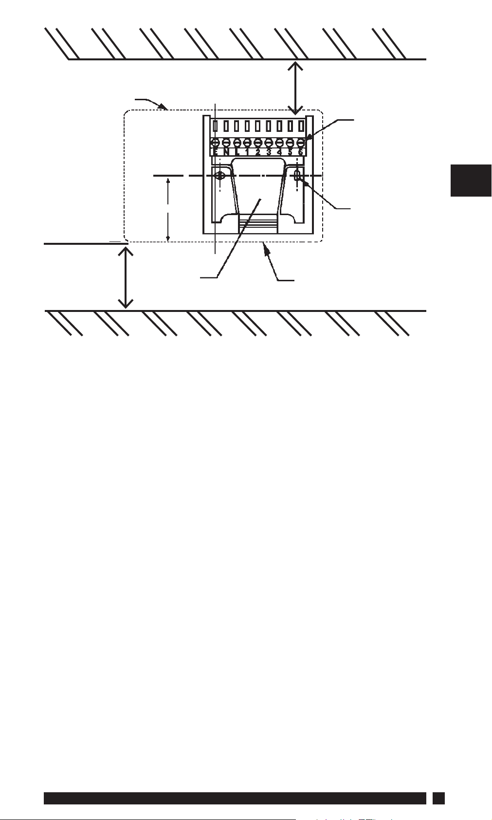
Leave suffi cient space
Outline of
programmer
Leave at least
25mm below
product
C/L
Rear entry
cable access
for screwdriver access
Terminal
block
Wall or
plasterbox
fi xing
Cable aperture
knockouts
5. Referring to the wiring diagrams on page 6-12, connect the unit as
shown.
GB
6. The unit is supplied ready for use in systems having PUMPED
primaries.
Should the unit be required for use in a system having GRAVITY
primaries, fi t the small plastic shorting link (which can be found
taped below the left hand fi xing screw hole of the wallplate) over
the two pins on the rear of the plug-in module. These pins can
be found in the recess near to the bottom edge of the plug-in
module.
7. Ensure all dust and debris are cleared from the area.
8. Locate the module on the latches at the bottom of the wallplate
and hinge upwards to fully engage the unit connectors into the
wallplate. Tighten the two fi xing screws to secure the unit to the
wallplate.
9. Before setting the programme, check the unit and circuit.
Switch ON the mains supply and press both WATER and
HEATING rocker switches to the CONSTANT position - both red
LED’s should now be illuminated. Adjust any remote thermostat
to check the services operate correctly.
Danfoss Heating
5
Page 6

10. Then press both WATER and HEATING rocker switches to the OFF
position and check that both services do not operate.
11. Finally, press both WATER and HEATING rocker switches to
TIMED position prior to programming the unit.
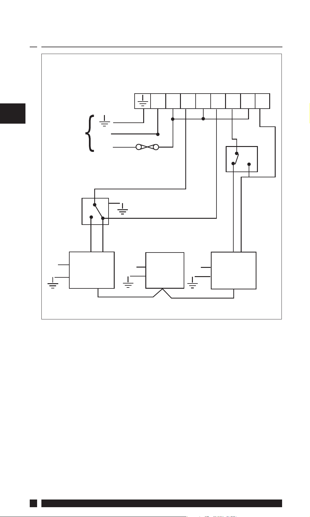
3.1 Wiring
GB
Typical wiring diagrams for various types of systems are shown on
the following pages.
Note: Whilst every attempt has been made to ensure the accuracy of this
information it is recommended that the specifi c information relating to
the ancillary controls is obtained from the manufacturers concerned.
TIMER
NOTES:
FOR SET2E LINK
TERMINALS 1 & 5
FP975 ON A SET
WALLPLATE
N/O
N/C
N/O
N/C
N
NOTE: For mains voltage applications links must be fi tted between
terminals L, 2 and 5.
L123
ON
COM
DHW
OFF
45
ON
COM
HTG
6
OFF
6
SET3M
Page 7

3.2 Typical Gravity DHW Pumped HTG
Mains
Supply
Terminals
N
L
N
D.H.W
on-com-off
HTG
/on-com-off
N L 1 2 3 4 5 6
3 amp fuse
N
Boiler Pump
GB
Room Stat
Other Danfoss Randall products suitable for use with above circuit:RMT room thermostat.
Danfoss Heating
7
Page 8

3.3 Typical Fully Pumped System with Spring
Return Zone Valve in Heating
GB
Mains
Supply
Cylinder
Stat
N
Terminals
N
L
Boiler
and
Pump
N L 1 2 3 4 5 6
3 amp fuse
D.H.W
on-com-off
N
S.R.Z.V
HTG
/on-com-off
Room Stat
in
HTG
Other Danfoss Randall products suitable for use with above circuit:AT cylinder thermostat;
RMT room thermostat;
HP22 or HP28 motorised zone valve with spring return actuator and
SPST auxiliary switch.
8
SET3M
Page 9

3.4 Typical Gravity DHW Pumped HTG with
t
Spring Return Zone Valve in DHW
Mains
Supply
Cylinder
Stat
N
Terminals
N
L
S.R.Z.V
in
DHW
N L 1 2 3 4 5 6
3 amp fuse
N
on-com-off
Boiler
D.H.W
N
HTG
/ on-com-off
GB
Room Sta
Pump
Other Danfoss Randall products suitable for use with above circuit:AT cylinder thermostat;
RMT room thermostat;
HP28C motorised zone valve with spring return actuator and SPDT
auxiliary switch.
Danfoss Heating
9
Page 10

3.5 Typical Fully Pumped System with 3-Port
Mid-Position Valve
GB
Mains
Supply
Cylinder
Stat
N
Terminals
N
L
Boiler
and
Pump
N L 1 2 3 4 5 6
3 amp fuse
on-com-off
N
D.H.W
/ on-com-off
3-port
mid-position
valve
HTG
Room Stat
Other Danfoss Randall products suitable for use with above circuit:AT cylinder thermostat;
RMT room thermostat;
HS3 3-port mid-position valve with spring return actuator.
10
SET3M
Page 11

3.6 Typical Fully Pumped System with Spring
t
Return Zone Valve in each Service
Mains
Supply
Cylinder
Stat
Terminals
N
L
3 amp fuse
D.H.W
on-com-off
N L 1 2 3 4 5 6
HTG
/ on-com-off
Room Sta
GB
N
Other Danfoss Randall products suitable for use with above circuit:AT cylinder thermostat;
RMT room thermostat;
2 x HP22 or HP28 motorised zone valve with spring return actuator
and SPST auxiliary switch.
S.R.Z.V
in
DHW
N
Boiler
and
Pump
N
S.R.Z.V
in
HTG
Danfoss Heating
11
Page 12
3.7 Typical Fully Pumped System with Fully
Motorised Zone Valve in each Service
GB
Mains
Supply
Cylinder
Stat
Terminals
N
L
3 amp fuse
D.H.W
on-com-off
N L 1 2 3 4 5 6
HTG
/ on-com-off
Room
Stat
N
Other Danfoss Randall products suitable for use with above circuit:AT cylinder thermostat;
RMT room thermostat.
F.M.Z.V
in
DHW
N
Boiler
and
Pump
N
F.M.Z.V
in
HTG
12
SET3M
Page 13

4.0 Replacement
Please see overleaf for a table containing replacement wiring
information.
Some time controls are connected in diff erent ways depending upon
the type of system and/or the controls which are fi tted. Consult
the column headed “NOTE: The conversion applies only if....”
to determine how the SET3M programmer’s GRAVITY or PUMPED
link should be set. If there is any doubt about the way in which the
existing programmer is connected, please contact our Technical
Services Department before proceeding with replacement.
Note: The SET3M is a direct plug-in replacement for any
existing programmers using the British Gas Standard Wallplate.
This includes the Horstmann 425 Tiara and Diadem electromechanical and 525 & 527 electronic programmers.
GB
Danfoss Heating
13
Page 14

GB
only applies if...
NOTE: This conversion
set to pumped
Pumped/Gravity link is
linked
Terminals 5,8 & 10 are
45 678 9
linked
set to pumped
Terminals 5 & 7 are
Pumped/Gravity link is
14
MAINS WATER HEATING
Danfoss Randall
N L ON COM OFF ON COM OFF
NL1 2 3 4 5 6 A BCD
SET3M
(PUMPED)
1,
1-0
2,3 1 5 - 4 7 - 6 8
Danfoss Randall 922/972 N L 3 2 1 6 5 4
Glowworm Mastermind N L 3 - 1 4 - 2
Horstmann 423
Amethyst 7 & 10
Horstmann 424 GEM 2,3
Horstmann Leucite 423 & 424 2 1 3 5 4 6 7 8
Honeywell ST669 N L 6 8 7 3 5 4
Landis & Gyr RWB2 N L 3 - 1 4 - 2
Potterton Mini-Minder N L 3 - 1 4 - 2
Potterton EP2000, EP3000 N L 3 - 1 4 5 2 A B C D
Randall 3033 1,7 6 4 - 5 2 - 3
Danfoss Randall 4033 7 6 4 1 5 2 - 3
L 2 - - 5 - - 6,4
N,
1,3
Sangamo Form 1 410 & 414 4,5 6 1 3 2 8 - 7
Sangamo S409/1
SET3M
Page 15

only applies if...
NOTE: This conversion
set to Pumped
Pumped/Gravity link is
ABC
set to Pumped
Pumped/Gravity link is
3A-
A/-S,-
/S,3
A/-S,5
independent control of
Used in a system having
GB
hot water
NL1 2 3 4 5 6 A BCD
N L ON COM OFF ON COM OFF
MAINS WATER HEATING
Danfoss Randall
SET3M
(PUMPED)
Danfoss Heating
L 1 - - A/S - -
N,
2,4
Sangamo S409/3 3,6 7 5 - 4 1 - 2
Satchwell ‘Libra’ & DHP 2201 1 2 6 7 8 3 4 5
Satchwell ET 1401 & ET 1451 1 2 7 6 8 4 3 5
Smith Ind Centroller 90 1 2 5 - - 4 - - 3 6
Smith Ind Centroller 1000 N L 3 - 1 4 - 2
Switchmaster 800 & 805 N L 3 - 4 1 - 2
Switchmaster 900 & 9000 N L 3 - 4 1 - 2
Venner CHC/W2 (with stat)
L1 - - 3 - -
N,
2,4
N,3 L 2 - 1 A/S - 4
Venner CHC/W2 (air stat linked)
Venner Ventrolnol 80M & 80PM
N,3 L 2 - 1 5 - 4
(with air stat)
Venner Ventrolnol 80M & 80PM
(air stat linked)
15
Page 16

Danfoss Randall Ltd.
Ampthill Road
Bedford MK42 9ER
Tel: 0845 1217 400
Fax: 0845 1217 515
Email: danfossrandall@danfoss.com
Website: www.danfoss-randall.co.uk
Part No. 3547v01 03/11
 Loading...