

Page 1
MAKING MODERN LIVING POSSIBLE
Danfoss Heating
SET 1E
Electronic Timeswitch
for Heating and Hot Water
Installation Guide
Page 2

For a large print version of these instructions
please call Marketing on 0845 121 7400.
®
Certification Mark
Danfoss can accept no responsibility for possible errors in catalogues, brochures, and other
printed material. All trademarks in this material are property of the respective companies.
Danfoss and the Danfoss logotype are trademarks of Danfoss A/S. All rights reserved.
2
SET1E
Page 3
Installation Instructions
SET1E
Electronic Timeswitch for Heating and Hot Water
GB
Index
1.0 Installation Guide .....................................................................................4
2.0 System Overview .......................................................................................4
3.0 Installation ...................................................................................................4
3.1 Wiring .....................................................................................................6
3.2 Typical gravity DHW with pumped central heating ..............7
3.3 Typical control of pump for central heating in a
solid fuel system .................................................................................8
3.4 Typical control heating function only with boiler
and pump .............................................................................................9
3.5 Typical control of a motorised zone valve
requiring an open and close signal .......................................... 10
3.6 Typical control of heating when used with
combination type boilers............................................................. 11
4.0 Replacement ............................................................................................. 11
Danfoss Heating
3
Page 4
GB
1.0 Installation Guide
Please Note:
This product should only be installed by a qualifi ed electrician or
competent heating installer and should be in accordance with the
current edition of the IEEE wiring regulations.
2.0 System Overview
Specifi cation
Power supply 230 ± 15% Vac, 50/60Hz
Switch action 1 x SPDT voltage free Type 1B
Switch rating
Timing accuracy ± 1 min/month
Power reserve Minimum 10 hours
Enclosure rating IP30
Max. ambient temperature 45°C
Dimensions, mm (W, H, D) 158 x 98 x 38
Design standard EN 60730-2-7
Control Pollution Situation Degree 2
Rated Impulse Voltage 2.5kV
Ball Pressure Test 75°C
Max. 264Vac, 50/60Hz, 3(1) A
3.0 Installation
1. Fix the wallplate to the wall or fl ush mounted box as required.
The connections are at the top and the vertical centre line of the
unit, at the position shown on the diagram below C/L (in line with
terminal
).
2. Surface cables can only enter from below the unit. If mounted on
a fl ush mounted box, cables can enter from the rear through the
aperture in the wallplate.
3. For mains voltage applications a link must be fi tted between
terminals L and 5.
4. Whilst the unit does not require an Earth connection, a terminal is
provided on the wallplate for Earth continuity purposes.
4
SET1E
Page 5
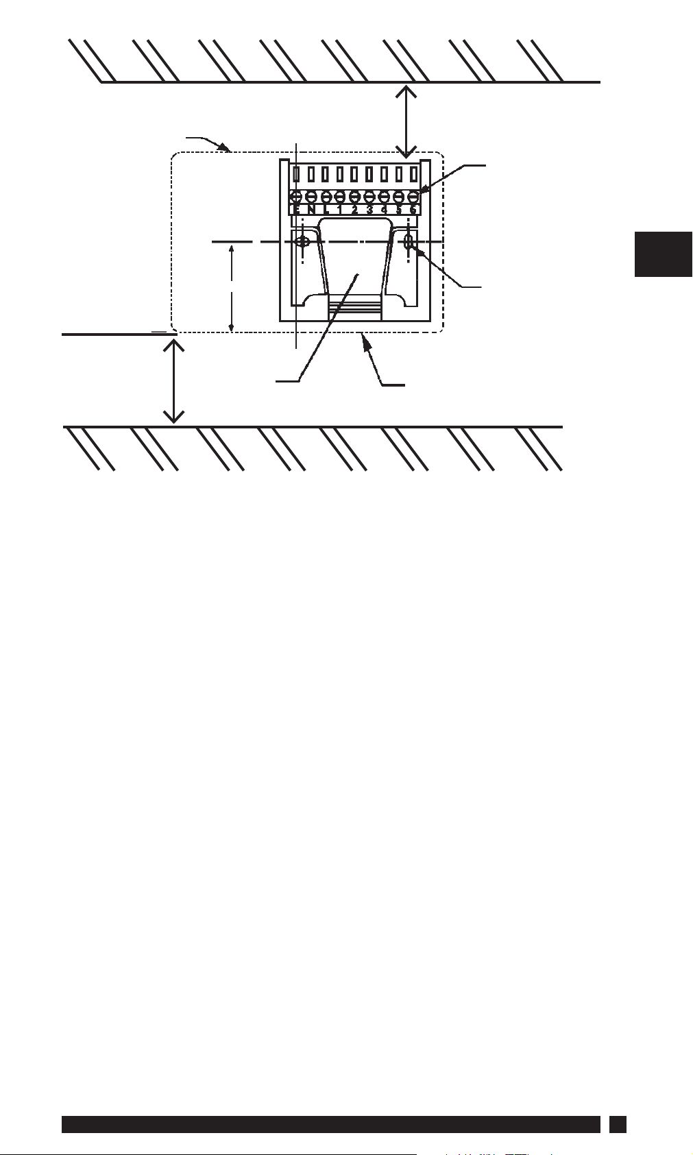
Outline of
programmer
Leave suffi cient space for
screwdriver access
C/L
Terminal
block
Wall or
plasterbox
fi xing
Leave at least
25mm below
product
Rear entry
cable access
Cable aperture
knockouts
5. Referring to the wiring diagrams on page 6-10, connect the unit
as shown.
6. Ensure all dust and debris are cleared from the area.
GB
7. Locate the module on the latches at the bottom of the wallplate
and hinge upwards to fully engage the unit connectors into the
wallplate. Tighten the two fi xing screws to secure the unit to the
wallplate.
8. Before setting the programme, check the unit and circuit. Switch
on the mains supply and press the rocker switch to the CONSTANT
position - the red LED should now be illuminated. Adjust any
remote thermostat to check the services operate correctly.
9. Press the rocker switch to the OFF position and check that the
system does not operate.
10. Finally, press the rocker switch to TIMED position prior to
programming the unit.
Danfoss Heating
5
Page 6

GB
3.1 Wiring
On the following pages are typical wiring diagrams for various types
of systems.
Note: Whilst every attempt has been made to ensure the accuracy of this
information it is recommended that the specifi c information relating to
the ancillary controls is obtained from the manufacturers concerned.
ELECTRONICS
N/O
NL1234
COM
TS975 ON A SET WALLPLATE
NOTE:
For mains voltage applications a link must be fi tted between
terminals L and 5.
ON
5
N/C
6
OFF
6
SET1E
Page 7
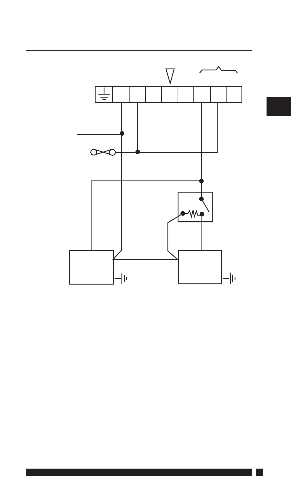
3.2 Typical Gravity DHW With Pumped Central
Heating
SPARE LOAD
ON OFF
Timeswitch
Terminals
N L 1 2 3 4 5 6
GB
Mains
Supply
N
L
3 amp
fuse max.
L
Boiler
COM
N
CALL
NN
Pump
Room
Stat
DHW = Domestic Hot Water
Danfoss Heating
7
Page 8
GB
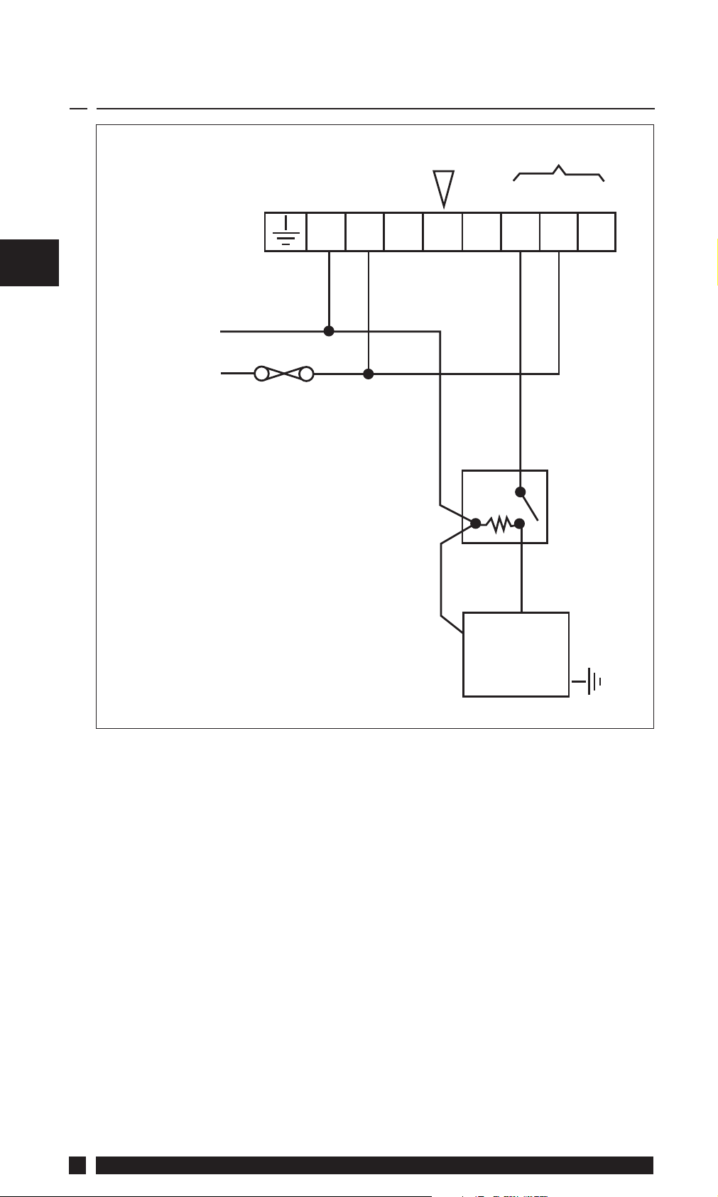
3.3 Typical Control of Pump For Central Heating
on a Solid Fuel System
SPARE LOAD
ON OFF
Timeswitch
Terminals
N L 1 2 3 4 5 6
Mains
Supply
N
L
3 amp
fuse max.
N
N
COM
Room
Stat
CALL
L
Pump
8
SET1E
Page 9

3.4 Typical Control Heating Function Only With
Boiler and Pump
SPARE LOAD
ON OFF
Timeswitch
Terminals
N L 1 2 3 4 5 6
GB
Mains
Supply
N
L
3 amp
fuse max.
N
L
Boiler Pump
N
N
COM
Room
Stat
CALL
Danfoss Heating
9
Page 10

GB
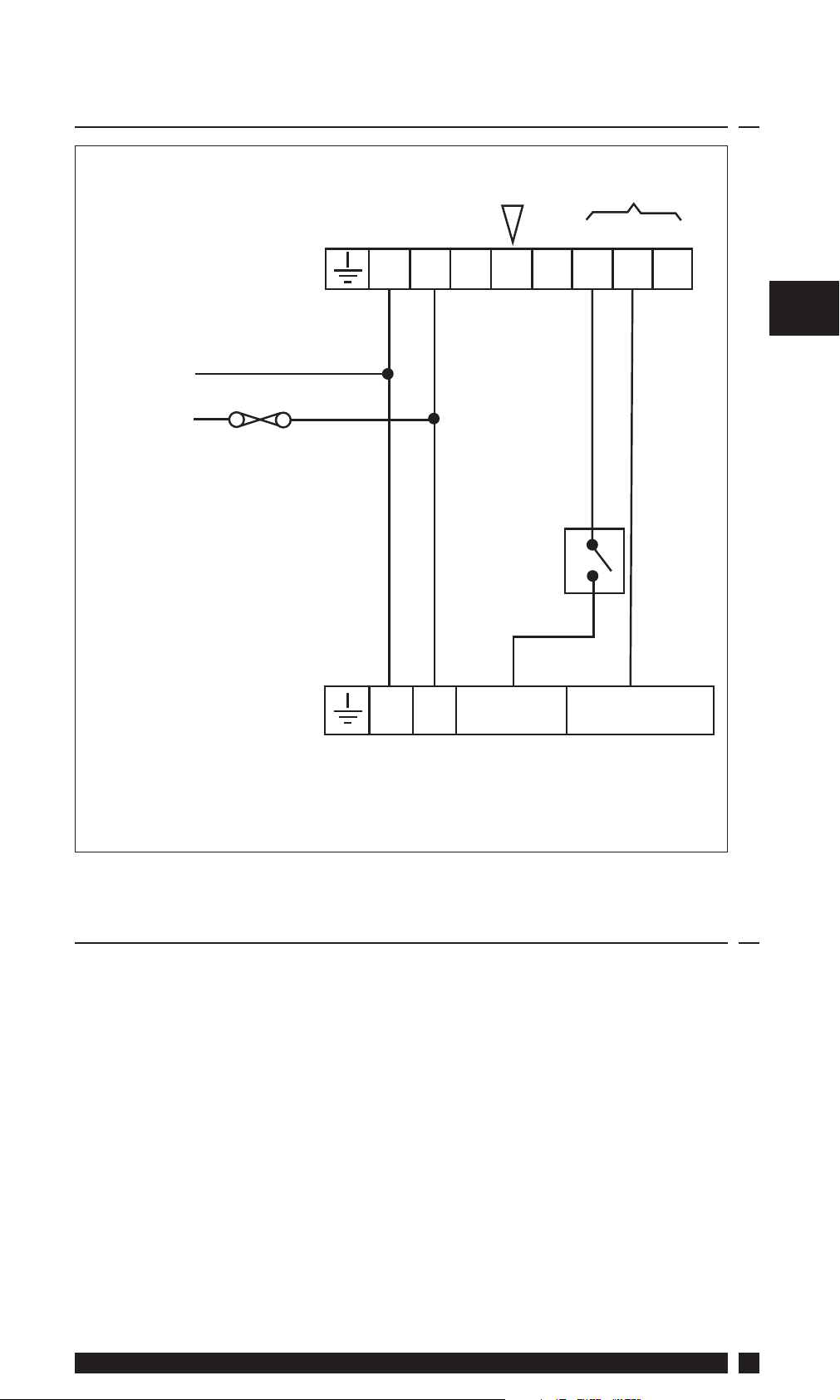
3.5 Typical Control of a Motorised Zone Valve
Requiring an Open and Close Signal
SPARE LOAD
ON OFF
Timeswitch
Terminals
N L 1 2 3 4 5 6
Mains
Supply
Aux. Switch Wire
N
L
3 amp
fuse max.
Room
Stat
CALL SAT
OPEN
COM
Zone
Valve
CLOSE
10
SET1E
Page 11
3.6 Typical Control of Heating When Used with
Combination Type Boilers
SPARE LOAD
ON OFF
Timeswitch
Terminals
N L 1 2 3 4 5 6
GB
Mains
Supply
N
L
3 amp
fuse max.
Boiler
Terminals
COM
Room
Stat
CALL
N L INPUT OUTPUT
4.0 Replacement
Please see overleaf for a table containing replacement wiring
information.
Some timeswitches are connected in diff erent ways depending upon
the type of system and/or the controls which are fi tted. If there is any
doubt about the way in which the existing timeswitch is connected,
please contact our Technical Services Department before proceeding
with replacement.
Note: The SET1E is a direct replacement for a Danfoss Randall
SET1.
Danfoss Heating
11
Page 12

GB
Additional terminal block
LOAD
SPARE TERMINAL
Where disconnected
pairs) should be terminated
terminated
leads should be
disconnected leads (or
is required where these
12
MAINS
DANFOSS RANDALL
SET1E
N L ON COM OFF
NL 2 4 5 6ABCD
ACL LS111 N L 4 3 1 2
NL1 2 4 3 - 5
DANFOSS RANDALL SET 1 N L 2 4 5 6
DANFOSS RANDALL 911 N L 2 6 5 4
DANFOSS RANDALL 103/103E 5 6 2 1 3 -
DANFOSS RANDALL 3020 1,7 6 2 4 - - 3 5
DANFOSS RANDALL TSR2 3 2 4 5 1 - 6 7
GRASSLIN 45, 45A, 45E 2 1 4 3 -
HORSTMANN 424 EMERALD & PEARL
NL 1 4 3 -256
AUTO RANGE
HORSTMANN 423 PEARL
EMERALD & TOPAZ
HORSTMANN KMK2A YMK2 3 4 2 1 -
HONEYWELL ST6100A N L 3 4 1 2
HONEYWELL ST6100C N L 3 4 1 2
HORSTMANN 425 CORONET N L 1 4 5 6 2 3
LANDIS & GYR RWB3 N L 1 4 - 3 2
SET1E
Page 13

SWITCH
GB
-
LIVE
LOAD
LIVE
MOTOR
N
NL 2 3 - 1
NL 3 2 1
LANDIS & GYR RWB30 N L 1 4 2 3
SANGAMO M6 4,5 6 7 1 3 2 8
SANGAMO 410 F8 4,5 3 6 1 - 2 7 8
SANGAMO S254 F2, S408 F5, S251 F2 N L LOAD - -
Danfoss Heating
SANGAMO S409 F8 3,N 5,L 1 2 6 -
SANGAMO S263 F2, S264 F2 N L ON - OFF
SMITH IND. MKI, MKII N L P1 P3 P2 -
SMITH IND. CENTROLLER 30 1 2 3 4,5 - - 6
SMITH IND. CENTROLLER 40 1 2 3 4,5 - -
SANGAMO S610 F2, S611 F2,
S162 F2, S408 F4, S408 F6,
S253 F2, S255 F2
SWITCHMASTER 300 N L 2 1 4 - 3
TOWERCHRON TC 2 1 3 7 4 - 8 9 10 11
VENNER VENNERETTE MK.IIA N L LOAD LINE -
VENNER VENNERETTE MK.IVA 2 3 1 4 -
VENNER VENOTIME
(WITH NEON INDICATING CIRCUIT ON)
VENNER VENOTIME (WITH
NEON INDICATING POWER ON)
VENNER VENNERON, VENNERON P 3 2 4 1
13
Page 14

14
SET1E
Page 15

Danfoss Heating
15
Page 16

Danfoss Ltd
Ampthill Road
Bedford MK42 9ER
Tel: 01234 364621
Fax: 01234 219705
Email: ukheating@danfoss.com
Website: www.heating.danfoss.co.uk
Part No. 8635v01s6-1 02/11
 Loading...