

Page 1
Technical Information
Series 90
Axial Piston Pumps
www.danfoss.com
Page 2
Technical Information
Series 90 Axial Piston Pumps
Revision history Table of revisions
Date Changed Rev
March 2022 Additional note onto Mating pump requirements at Features and Options 0910
September 2021 Modified KN at control option "M" on MMC 0909
June 2021 Deleted Size 042 information. 0908
March 2020 Removed restricted options 0907
February 2020 Changed document number from BC00000015 and increased version by 0101 0906
January 2020 Corrected 075 dimension drawing 0805
March 2016 Minor edit 0804
January 2015 correction to O-ring sizing - page 77 HC
May 2014 corrections to pin assignments - page 48 HB
February 2014 Danfoss Layout HA
2 | © Danfoss | March 2022 BC152886483413en-000910
Page 3

Technical Information
Series 90 Axial Piston Pumps
Contents
General Description
Series 90 Family of Pumps and Motors.....................................................................................................................................5
PLUS+1 Compliant Controls and Sensors................................................................................................................................5
Design...................................................................................................................................................................................................6
Series 90 Pictorial Circuit Diagram............................................................................................................................................. 7
System schematic.............................................................................................................................................................................7
Technical Specifications
General Specifications.................................................................................................................................................................... 8
Features and Options......................................................................................................................................................................8
Operating Parameters.....................................................................................................................................................................9
Fluid Specification............................................................................................................................................................................9
Operating Parameters
Input Speed......................................................................................................................................................................................10
Independent Braking System...............................................................................................................................................10
System Pressure..............................................................................................................................................................................10
Servo Pressure.................................................................................................................................................................................12
Charge Pressure..............................................................................................................................................................................12
Charge Pump Inlet Pressure.......................................................................................................................................................12
Case Pressure...................................................................................................................................................................................12
External Shaft Seal Pressure....................................................................................................................................................... 13
Temperature.................................................................................................................................................................................... 13
Viscosity.............................................................................................................................................................................................13
System Design Parameters
Filtration System.............................................................................................................................................................................14
Filtration Options...........................................................................................................................................................................14
Suction filtration – Option S................................................................................................................................................. 14
Charge pressure filtration (partial charge pump flow)............................................................................................... 15
Remote charge pressure filtration......................................................................................................................................15
Fluid Selection.................................................................................................................................................................................15
Reservoir............................................................................................................................................................................................15
Case Drain.........................................................................................................................................................................................16
Pump Life..........................................................................................................................................................................................16
Charge Pump...................................................................................................................................................................................16
Charge pump sizing/selection.............................................................................................................................................16
Bearing Loads and Life.................................................................................................................................................................17
Applications with external shaft loads..............................................................................................................................17
Understanding and Minimizing System Noise....................................................................................................................18
Sizing Equations............................................................................................................................................................................. 18
Mounting Flange Loads...............................................................................................................................................................19
Master Model Code
Series 90 Master Model Code Breakdown............................................................................................................................ 21
S90 Rotation and Size Options..................................................................................................................................................21
Control Options.............................................................................................................................................................................. 22
Pressure, Aux Mounting, Ports, Filtration, Displacement Limitation Options......................................................... 23
Shaft and Charging System........................................................................................................................................................24
Control Orifice Options................................................................................................................................................................25
Special Hardware and Pressure Settings...............................................................................................................................26
Control Features
3-Position (FNR) Electric Control - DC, DD............................................................................................................................ 27
Response time........................................................................................................................................................................... 28
Electric Displacement Control (EDC), Options KA, KP, KT................................................................................................28
Features and Benefits..............................................................................................................................................................28
Response time........................................................................................................................................................................... 31
Pump output flow direction vs. control current............................................................................................................31
Manual Over Ride (MOR)............................................................................................................................................................. 32
Hydraulic Displacement Control (HDC), Option HF, HS...................................................................................................33
©
Danfoss | March 2022 BC152886483413en-000910 | 3
Page 4

Technical Information
Series 90 Axial Piston Pumps
Contents
Operation.....................................................................................................................................................................................33
Features and Benefits..............................................................................................................................................................33
Response time........................................................................................................................................................................... 34
Pump output flow direction vs. control pressure.........................................................................................................34
Manual Displacement Control (MDC), Options MA, MB.................................................................................................. 35
Features and benefits..............................................................................................................................................................35
External control handle requirements..............................................................................................................................36
Response Time...........................................................................................................................................................................36
Pump output flow direction vs. control handle rotation...........................................................................................37
Neutral start switch (NSS) for MDC..........................................................................................................................................37
Non Feedback Proportional Electric Control (NFPE) ........................................................................................................37
Control response.......................................................................................................................................................................37
NFPE control used with a Danfoss microcontroller......................................................................................................38
Input signal requirements.....................................................................................................................................................38
Features and Options
Multi-Function Valves...................................................................................................................................................................40
Overpressure protection........................................................................................................................................................40
Pressure limiting function..................................................................................................................................................... 40
Bypass Function........................................................................................................................................................................ 41
Auxiliary Mounting Pads............................................................................................................................................................. 41
Mating pump requirements................................................................................................................................................. 41
Displacement Limiter................................................................................................................................................................... 42
Shaft Torque.....................................................................................................................................................................................43
Shaft torque and spline lubrication................................................................................................................................... 43
Shaft torque for tapered shafts............................................................................................................................................43
Shaft Availability and Torque Ratings.....................................................................................................................................44
Tapered Shaft Customer Acknowledgement.................................................................................................................45
Charge Pump...................................................................................................................................................................................45
Charge pump sizing/selection.............................................................................................................................................45
Charge pump flow and power curves...............................................................................................................................46
Speed Sensor...................................................................................................................................................................................47
Connector Pin Assignments.......................................................................................................................................................49
Installation Drawings
Frame Size 055................................................................................................................................................................................ 50
Frame Size 075................................................................................................................................................................................ 54
Frame Size 075 NFPE Options FK, FL, FM, FN.......................................................................................................................57
Frame Size 100................................................................................................................................................................................ 62
Frame Size 130................................................................................................................................................................................ 67
Frame Size 180................................................................................................................................................................................ 71
Frame Size 250................................................................................................................................................................................ 75
Cover Plate........................................................................................................................................................................................78
3-Position (F-N-R) Electric Control........................................................................................................................................... 79
Electric Displacement Control (EDC) with MS-Connector or Packard® connector.................................................80
Hydraulic Displacement Control (HDC)................................................................................................................................. 80
Manual Displacement Control (MDC) with neutral start switch................................................................................... 81
Electrohydraulic Displacement Control (NFPE)(except 075 NFPE).............................................................................. 82
Integral Pressure Filter................................................................................................................................................................. 83
Remote pressure – without filter..............................................................................................................................................83
4 | © Danfoss | March 2022 BC152886483413en-000910
Page 5

Technical Information
Series 90 Axial Piston Pumps
General Description
Series 90 Family of Pumps and Motors
Series 90 hydrostatic pumps and motors can be applied together or combined with other products in a
system to transfer and control hydraulic power. They are intended for closed circuit applications.
Series 90 – advanced technology
•
Seven sizes of variable displacement pumps
•
Proven reliability and performance
•
Compact, lightweight
•
Worldwide sales and service
•
PLUS+1™ compliant controls and sensors
•
Series 90 variable displacement pumps are compact, high power density units. All models utilize the
parallel axial piston/slipper concept in conjunction with a tiltable swashplate to vary the pump’s
displacement. Reversing the angle of the swashplate reverses the flow of oil from the pump and thus
reverses the direction of rotation of the motor output.
Series 90 pumps include an integral charge pump to provide system replenishing and cooling oil flow, as
well as control fluid flow. They also feature a range of auxiliary mounting pads to accept auxiliary
hydraulic pumps for use in complementary hydraulic systems. A complete family of control options is
available to suit a variety of control systems (mechanical, hydraulic, electric).
Series 90 motors also use the parallel axial piston/slipper design in conjunction with a fixed or tiltable
swashplate. They can intake/discharge fluid through either port; they are bidirectional. They also include
an optional loop flushing feature that provides additional cooling and cleaning of fluid in the working
loop. For more information on Series 90 motors, refer to Series 90 Motors Technical Information
BC152886483265.
PLUS+1 Compliant Controls and Sensors
A wide range of Series 90 controls and sensors are PLUS+1™ compliant. PLUS+1 compliance means our
controls and sensors are directly compatible with the PLUS+1 machine control architecture. Adding
Series 90 pumps to your application using PLUS+1 GUIDE software is as easy as drag-and-drop. Software
development that used to take months can now be done in just a few hours. For more information on
PLUS+1 GUIDE, visit www.sauer-danfoss.com/plus1.
Series 90 pumps can be used together in combination with other Danfoss pumps and motors in the
overall hydraulic system. Danfoss hydrostatic products are designed with many different displacement,
pressure and load-life capabilities.
Go to the Danfoss website or applicable product catalog to choose the components that are right for
your complete closed circuit hydraulic system.
©
Danfoss | March 2022 BC152886483413en-000910 | 5
Page 6
P106 648E
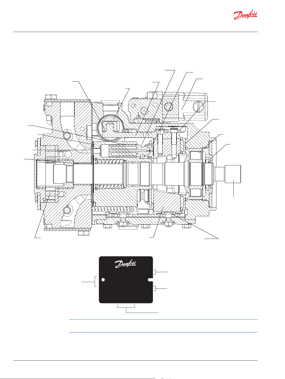
Slider block
Servo piston
Servo arm
Displacement control
Cradle bearing
Charge pump
Swashplate
Cradle guide
Feedback linkage
Roller bearing
Shaft
Piston
Slipper
Valve plate
Cylinder block
Input shaft
Rear
bushing
Bushing
seal
Model-No./Ident-No.
Model Code
Serial-No.
Made in USA
Place of Manufacture
Model
Number
Serial
Number
Model
Code
A - 88 - 126 - 67890
501829
P108494E
90L055 KA 1 N
6 S 3 C6 C 03
NNN 35 35 24
Technical Information
Series 90 Axial Piston Pumps
General Description
Design
Series 90 pump cross-section
Typical name plate
Series 90 pumps are also manufactured in Europe and China. Place of manufacture shown on nameplate
will correspond with the actual place of manufacture.
6 | © Danfoss | March 2022 BC152886483413en-000910
Page 7
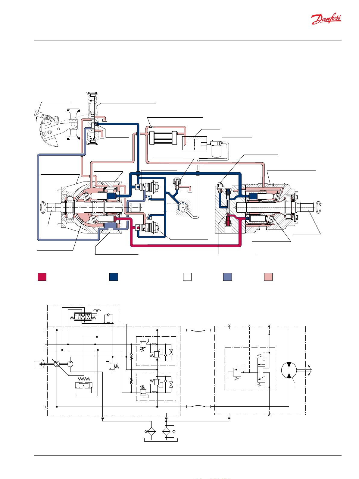
Pump Motor
Working loop (low pressure)
Control fluid
Suction line
Case drain fluid
Working loop (high pressure)
Motor swashplate
Loop flushing valve
Displacement control valve
Heat exchanger bypass valve
Reservoir
Vacuum gauge
Purge relief valve
Fixed displacement motor
Output shaft
Multi-function valve
Charge pump
To
pump
case
Servo
pressure
relief valves
Servo control cylinder
Pump swashplate
Input shaft
Reversible variable
displacement pump
Servo control cylinder
Heat exchanger
Multi-function valve
Charge pressure relief valve
Orificed check
valve
Control handle
P102 000
M
BB
L2
M2
M1
M4
M5
M3
A A
S
L2 M1
M2
L1
M3
P104 286E
Technical Information
Series 90 Axial Piston Pumps
General Description
Series 90 Pictorial Circuit Diagram
The circuit diagram shows a hydrostatic transmission using a Series 90 axial piston variable displacement
pump and a Series 90 fixed displacement motor.
System schematic
©
Danfoss | March 2022 BC152886483413en-000910 | 7
Page 8
Technical Information
Series 90 Axial Piston Pumps
Technical Specifications
General Specifications
Design Axial piston pump of cradle swashplate design with variable displacement
Direction of rotation Clockwise, counterclockwise
Pipe connections Main pressure ports: ISO split flange boss
Remaining ports: SAE straight thread O-ring boss
Recommended installation position Pump installation position is discretionary, however the recommended control position is on the top
or at the side, with the top position preferred.
Vertical input shaft installation is acceptable.
If input shaft is at the top 1 bar case pressure must be maintained during operation.
The pump housing must be filled with hydraulic fluid under all conditions; including after a long
period of shutdown. Before operating the machine, ensure the pump housing and case drain lines are
free of air.
Recommended mounting for a multiple pump stack is to arrange the highest power flow towards the
input source.
Consult Danfoss for nonconformance to these guidelines.
Auxiliary cavity pressure Will be inlet pressure with internal charge pump. For reference see Operating Parameters. Will be case
pressure with external charge supply.
Please verify mating pump shaft seal capability.
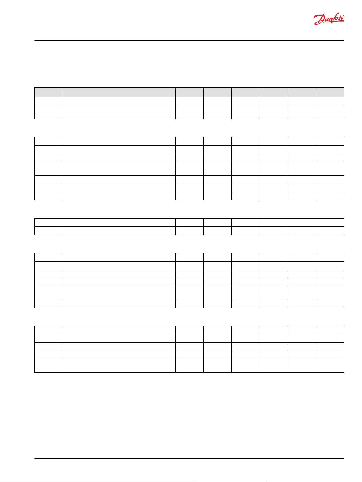
Features and Options
Feature Unit Frame
055 075 100 130 180 250
Displacement cm³/rev.
[in³]/rev.
Flow at rated speed (theoretical) l/min.
[US gal/min.]
Torque at maximum displacement
(theoretical)
Mass moment of inertia of rotating
components
Weight (with control opt. MA) kg [lb] 40 [88] 49 [108] 68 [150] 88 [195] 136 [300] 154 [340]
Mounting (per ISO 3019-1) Flange
Rotation Right hand or Left hand rotation
Main ports: 4-bolt split-flange
(per SAE J518 code 62)
Main port configuration Twin or side port Twin port
Case drain ports (SAE O-ring boss) UNF thread
Other ports SAE O-ring boss
Shafts Splined, and tapered shafts available
Auxiliary mounting SAE-A, B, C SAE-A, B, C, D SAE-A, B, C, D, E
N•m/bar
[lbf•in/1000
psi]
kg•m²
[slug•ft²]
mm
[in]
(in.)
55
[3.35]
215
[57]
0.88
[530]
0.0060
[0.0044]
127-4 (SAE C)
25.4
[1.0]
1.0625–12 1.0625–12 1.0625–12 1.3125–12 1.625–12 1.625–12
75
[4.59]
270
[71]
1.19
[730]
0.0096
[0.0071]
25.4
[1.0]
100
[6.10]
330
[87]
1.59
[970]
0.0150
[0.0111]
25.4
[1.0]
130
[7.93]
403
[106]
2.07
[1260]
0.023
[0.0170]
Flange
152-4 (SAE D)
31.75
[1.25]
180
[10.98]
468
[124]
2.87
[1750]
0.0380
[0.0280]
Flange
165-4 (SAE E)
31.75
[1.25]
250
[15.25]
575
[160]
3.97
[2433]
0.0650
[0.0479]
38.1
[1.5]
8 | © Danfoss | March 2022 BC152886483413en-000910
Page 9
Technical Information
Series 90 Axial Piston Pumps
Technical Specifications
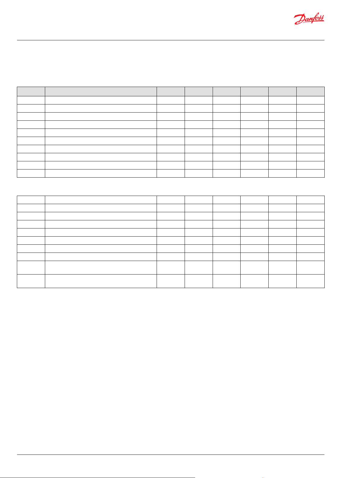
Operating Parameters
Parameter Unit Frame
055 075 100 130 180 250
Input speed
Minimum min-1(rpm) 500 500 500 500 500 500
Rated Speed 3900 3600 3300 3100 2600 2300
Maximum 4250 3950 3650 3400 2850 2500
Operating parameters
System pressure Maximum working pressure bar [psi] 450 [6525]
Maximum pressure 480 [6960]
Maximum low loop 45 [650]
Minimum low loop pressure 10 [145]
Charge pressure Minimum bar [psi] 18 [261]
Maximum 34 [493]
Control pressure Minimum (at corner power for EDC and FNR) bar [psi] 14 [203]
Minimum (at corner power for NFPE) 22 [319]
Maximum 40 [580]
Charge pump inlet
pressure
Case pressure Rated bar [psi] 3.0 [44]
Lip seal external pressure Maximum bar [psi] 0.4 [5.8}
Rated bar (absolute) [in Hg vacuum] 0.7 [9]
Minimum (cold start) 0.2 [24]
Maximum bar [psi] 4.0 [58]
Maximum 5.0 [73]
Fluid Specification
Viscosity
Intermittent
Minimum
Recommended range
Maximum
1)
Intermittent = Short term t < 1 min per incident and not exceeding 2 % of duty cycle based load-life.
1)
5 mm2/s [42 SUS]
7 mm2/s [49 SUS]
12 – 80 mm2/s [66 – 370 SUS]
1600 mm2/s [7500 SUS]
Temperature
Minimum
Rated
Recommended range
Maximum Intermittent
1)
Cold start = Short term t > 3 min, p ≤ 50 bar [725 psi], n ≤ 1000 min-1 (rpm).
2)
At the hottest point, normally case drain port.
©
Danfoss | March 2022 BC152886483413en-000910 | 9
1)
2)
-40°C [-40°F]
104°C [220°F]
60 – 85°C [140 – 185°F]
115°C [240°F]
Page 10

W
Technical Information
Series 90 Axial Piston Pumps
Operating Parameters
Input Speed
Minimum
speed
Rated speed is the highest input speed recommended at full power condition. Operating at or
Maximum
speed
During hydraulic braking and downhill conditions, the prime mover must be capable of providing
sufficient braking torque in order to avoid pump over speed. This is especially important to consider for
turbo-charged and Tier 4 engines.
For more information please see Pressure and Speed Limits, BC152886484313, when determining speed
limits for a particular application.
Independent Braking System
is the lowest input speed recommended during engine idle condition. Operating below
minimum speed limits the pump’s ability to maintain adequate flow for lubrication and
power transmission.
below this speed should yield satisfactory product life.
Operating conditions between rated and maximum speed should be restricted to less
than full power and to limited periods of time.
is the highest operating speed permitted. Exceeding maximum speed reduces product
life and can cause loss of hydrostatic power and braking capacity. For most drive
systems, maximum unit speed occurs during downhill braking or negative power
conditions.
Warning
Never exceed the maximum speed limit under any operating conditions.
System Pressure
Unintended vehicle or machine movement hazard. Exceeding maximum speed may cause a loss of
hydrostatic drive line power and braking capacity.
Machine manufacturer is responsible to provide a braking system, redundant to the hydrostatic
transmission, sufficient to stop and hold the vehicle or machine in the event of hydrostatic drive power
loss. The braking system must also be sufficient to hold the machine in place when full power is applied.
Hydraulic unit life depends on the speed and normal operating — or weighted average — pressure that
can only be determined from a duty cycle analysis.
System pressure is the differential pressure between high pressure system ports. It is the dominant
operating variable affecting hydraulic unit life. High system pressure, which results
from high load, reduces expected life.
Application
pressure
Maximum
working
pressure
is the high pressure relief or pressure limiter setting normally defined within the
order code of the pump. This is the applied system pressure at which the drive line
generates the maximum calculated pull or torque in the application.
is the highest recommended application pressure and is not intended to be a
continuous pressure. Propel systems with application pressures at, or below this
pressure should yield satisfactory unit life given proper component sizing.
Application pressures above maximum working pressure will only be considered
with duty cycle analysis and factory approval.
Pressure spikes are normal and must be considered when reviewing maximum
working pressure.
10 | © Danfoss | March 2022 BC152886483413en-000910
Page 11

Technical Information
Series 90 Axial Piston Pumps
Operating Parameters
Maximum
pressure
Minimum low
loop pressure
is the highest intermittent pressure allowed under any circumstances. Applications
with applied pressures between rated and maximum require factory approval with
complete application, duty cycle, and life expectancy analysis.
must be maintained under all operating conditions to avoid cavitation.
All pressure limits are differential pressures referenced to low loop (charge) pressure.
Subtract low loop pressure from gauge readings to compute the differential.
©
Danfoss | March 2022 BC152886483413en-000910 | 11
Page 12

Technical Information
Series 90 Axial Piston Pumps
Operating Parameters
Servo Pressure
Servo pressure is the pressure in the servo system needed to position and hold the pump on stroke. It
depends on system pressure and speed. At minimum servo pressure the pump will run at reduced stroke
depending on speed and pressure.
Minimum servo pressure at corner power holds the pump on full stroke at max speed and max
Maximum servo pressure is the highest pressure typically given by the charge pressure setting.
Charge Pressure
An internal charge relief valve regulates charge pressure. Charge pressure supplies the control with
pressure to operate the swashplate and to maintain a minimum pressure in the low side of the
transmission loop.
The charge pressure setting listed in the order code is the set pressure of the charge relief valve with the
pump in neutral, operating at 1800 min-1 (rpm), and with a fluid viscosity of 32 mm2/s [150 SUS].
Pumps configured with no charge pump (external charge supply) are set with a charge flow of 30 l/min
[7.93 US gal/min] and a fluid viscosity of 32 mm2/s [150 SUS].
The charge pressure setting is referenced to case pressure. Charge pressure is the differential pressure
above case pressure.
pressure.
Charge Pump Inlet Pressure
Case Pressure
Minimum
charge
pressure
Maximum
charge
pressure
At normal operating temperature charge inlet pressure must not fall below rated charge inlet pressure
(vacuum).
Minimum charge inlet
pressure
Maximum charge inlet
pressure
Under normal operating conditions, the rated case pressure must not be exceeded. During cold start case
pressure must be kept below maximum intermittent case pressure. Size drain plumbing accordingly.
The auxiliary pad cavity of axial pumps configured without integral charge pumps is referenced to case
pressure. Units with integral charge pumps have auxiliary mounting pad cavities referenced to charge
inlet (vacuum).
is the lowest pressure allowed to maintain a safe working condition in the low side of
the loop. Minimum control pressure requirements are a function of speed, pressure,
and swashplate angle, and may be higher than the minimum charge pressure shown
in the Operating parameters tables.
is the highest charge pressure allowed by the charge relief adjustment, and which
provides normal component life. Elevated charge pressure can be used as a
secondary means to reduce the swashplate response time.
is only allowed at cold start conditions. In some applications it is
recommended to warm up the fluid (e.g. in the tank) before starting the
engine and then run the engine at limited speed.
may be applied continuously.
Possible component damage or leakage.
Operation with case pressure in excess of stated limits may damage seals, gaskets, and/or housings,
causing external leakage. Performance may also be affected since charge and system pressure are
additive to case pressure.
12 | © Danfoss | March 2022 BC152886483413en-000910
Page 13

C
Technical Information
Series 90 Axial Piston Pumps
Operating Parameters
External Shaft Seal Pressure
In certain applications the input shaft seal may be exposed to external pressure. In order to prevent
damage to the shaft seal the maximum differential pressure from external sources must not exceed 0.4
bar (5.8 psi) over pump case pressure.
The case pressure limits of the pump must also be followed to ensure the shaft seal is not damaged.
Regardless of the differential pressure across the shaft seal, the shaft seal has been known to pump oil
from the external source (e. g. gear box) into the pump case.
Temperature
The high temperature limits apply at the hottest point in the transmission, which is normally the motor
case drain. The system should generally be run at or below the quoted rated temperature.
The maximum intermittent temperature is based on material properties and should never be
exceeded.
Cold oil will generally not affect the durability of the transmission components, but it may affect the
ability of oil to flow and transmit power; therefore temperatures should remain 16 °C [30 °F] above the
pour point of the hydraulic fluid.
The minimum temperature relates to the physical properties of component materials.
Size heat exchangers to keep the fluid within these limits. Danfoss recommends testing to verify that
these temperature limits are not exceeded.
Caution
Viscosity
For maximum efficiency and bearing life, ensure the fluid viscosity remains in the recommended range.
The minimum viscosity should be encountered only during brief occasions of maximum ambient
temperature and severe duty cycle operation.
The maximum viscosity should be encountered only at cold start.
©
Danfoss | March 2022 BC152886483413en-000910 | 13
Page 14
W
Charge pump
Filter
Hydraulic fluid reservoir
Adjustable
charge pressu re relief valve
To pump case
To low
loop and
control
Manomete r
P102 003E
Technical Information
Series 90 Axial Piston Pumps
System Design Parameters
Filtration System
To prevent premature wear, ensure only clean fluid enters the hydrostatic transmission circuit. A filter
capable of controlling the fluid cleanliness to ISO 4406 class 22/18/13
(SAE J1165) or better, under normal operating conditions, is recommended.
These cleanliness levels can not be applied for hydraulic fluid residing in the component housing/case or
any other cavity after transport.
The filter may be located on the pump (integral) or in another location (remote).
The integral filter has a filter bypass sensor to signal the machine operator when the filter requires
changing. Filtration strategies include suction or pressure filtration. The selection of a filter depends on a
number of factors including the contaminant ingression rate, the generation of contaminants in the
system, the required fluid cleanliness, and the desired maintenance interval. Filters are selected to meet
the above requirements using rating parameters of efficiency and capacity.
Filter efficiency can be measured with a Beta ratio¹ (βX). For simple suction-filtered closed circuit
transmissions and open circuit transmissions with return line filtration, a filter
with a β-ratio within the range of β
some open circuit systems, and closed circuits with cylinders being supplied from the same reservoir, a
considerably higher filter efficiency is recommended. This also applies to systems with gears or clutches
using a common reservoir.
For these systems, a charge pressure or return filtration system with a filter β-ratio in the range of β
75 (β10 ≥ 10) or better is typically required.
Because each system is unique, only a thorough testing and evaluation program can fully validate the
filtration system. Please see Design Guidelines for Hydraulic Fluid Cleanliness Technical Information,
BC152886482150 for more information.
1
Filter βx-ratio is a measure of filter efficiency defined by ISO 4572. It is defined as the ratio of the number
of particles greater than a given diameter (“x” in microns) upstream of the filter to the number of these
particles downstream of the filter.
= 75 (β10 ≥ 2) or better has been found to be satisfactory. For
35-45
15-20
=
Filtration Options
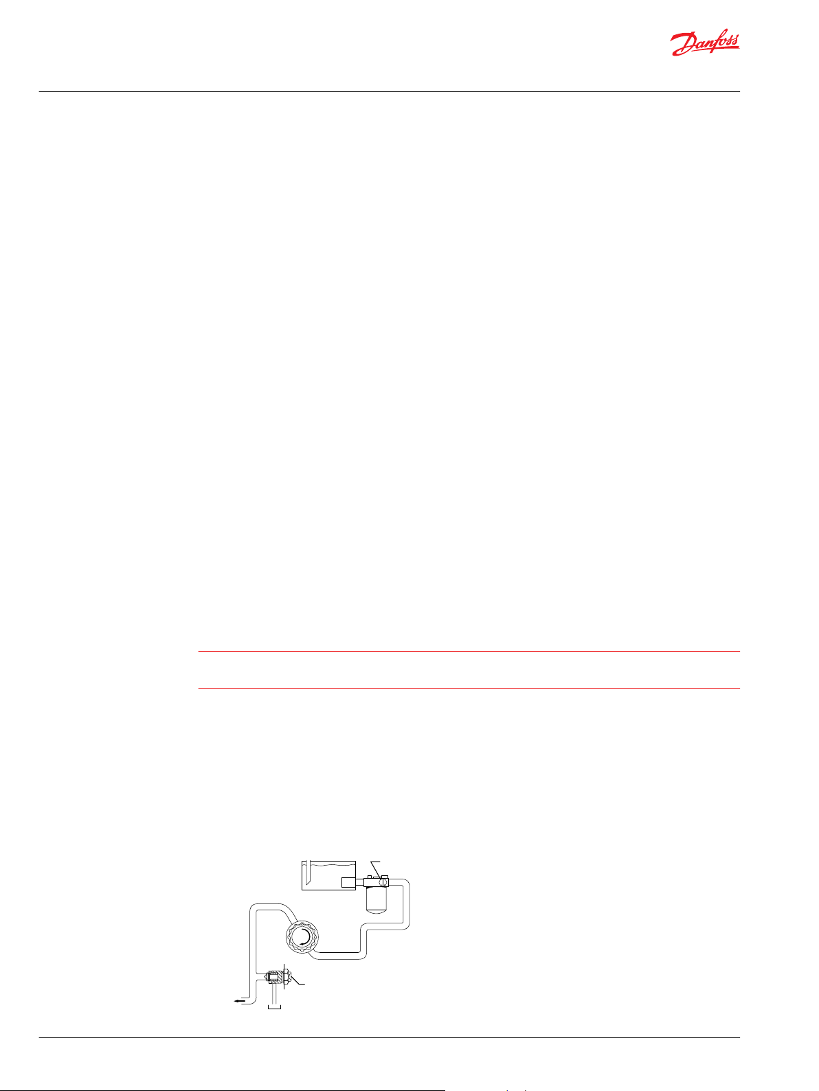
Warning
Clogged filters can cause cavitation, which damages the charge pump. We recommend a filter bypass
with a filter bypass sensor to prevent damage due to blocked suction filters.
Suction filtration – Option S
The suction filter is placed in the circuit between the reservoir and the inlet to the charge pump, as
shown below.
The use of a filter contamination monitor is recommended.
Suction filtration
14 | © Danfoss | March 2022 BC152886483413en-000910
Page 15
To pump case
Charge pump
Hydraulic fluid reservoir
Filter
To low
pressure
side and
control
Screen
Adjustable
charge pressure
relief valve
P102 004E
W
Technical Information
Series 90 Axial Piston Pumps
System Design Parameters
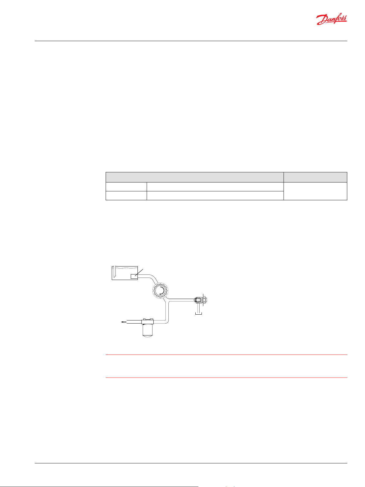
Charge pressure filtration (partial charge pump flow)
Two types of pressure filtration exist for most Series 90 pumps. The two types are: remote pressure
filtration (filter remotely mounted on vehicle) and integral pressure filtration (filter mounted to the
endcap). Verify option availability in the size specific technical information.
In either case the filtration circuit is the same with the filter element situated in the circuit downstream
the charge pump and upstream of the charge relief valve such that full charge flow is continuously
filtered, as shown in the accompanying illustrations. Charge pressure filtration can mitigate high inlet
vacuum in cold start-ups and provides fluid filtration immediately prior to entrance to the loop and the
control system. Pressure filtration provides a higher level of filtering efficiency than suction filtration.
Filters used in charge pressure filtration circuits must be rated to at least 35 bar [508 psi] pressure. A 100 –
125 μm screen located in the reservoir or in the charge inlet line is recommended when using charge
pressure filtration.
Technical data according to ISO 16889
Nominal flow at 30mm2/s and ∆P 0.5 bar[7.3 psi] (clean filter element only) Minimum β-ratio
Short 60 l/min β7.5(C)=75 (β5(C) ≥10)
Long 105 l/min
Remote charge pressure filtration
A special adapter head is available to allow for the charge filter to be located conveniently for easy
service and replacement. Care should be taken to minimize the hydraulic pressure drops associated with
long connecting lines, small diameter hoses, or restrictive port adaptors at the filter head or endcap.
Ensure the normal operating pressure drop across the remote filtration in and out ports is sufficiently
below the crack pressure setting of the recommended filter bypass valve.
Charge pressure filtration
Warning
Remote filter heads without bypass and poor plumbing design can encounter excessive pressure drops
that can lead to charge pump damage in addition to contaminants being forced through the filter media
and into the transmission loop.
Fluid Selection
Ratings and performance data are based on operating with hydraulic fluids containing oxidation, rust
and foam inhibitors. These fluids must possess good thermal and hydrolytic stability to prevent wear,
erosion, and corrosion of pump components.
Never mix hydraulic fluids of different types.
Reservoir
©
Danfoss | March 2022 BC152886483413en-000910 | 15
The hydrostatic system reservoir should accommodate maximum volume changes during all system
operating modes and promote de-aeration of the fluid as it passes through the tank. A suggested
Page 16

Technical Information
Series 90 Axial Piston Pumps
System Design Parameters
minimum total reservoir volume is 5⁄8 of the maximum charge pump flow per minute with a minimum
fluid volume equal to ½ of the maximum charge pump flow per minute. This allows 30 seconds fluid
dwell for removing entrained air at the maximum return flow. This is usually adequate to allow for a
closed reservoir (no breather) in most applications.
Locate the reservoir outlet (charge pump inlet) above the bottom of the reservoir to take advantage of
gravity separation and prevent large foreign particles from entering the charge inlet line. A 100-125 μm
screen over the outlet port is recommended. Position the reservoir inlet (fluid return) to discharge below
the normal fluid level, toward the interior of the tank. A baffle (or baffles) will further promote de-aeration
and reduce surging of the fluid.
Case Drain
All single S90 pumps are equipped with multiple drain ports. Port selection and case drain routing must
enable the pump housing to maintain a volume of oil not less than half full and normal operating case
pressure limits of the unit are maintained. Case drain routing and design must consider unit case pressure
ratings.
A case drain line must be connected to one of the case outlets to return internal leakage to the system
reservoir.
Do not over torque the fitting on case drain port L2 (located on the side cover). The proper torque is 100
N•m [74 lbf•ft] maximum. Over torquing the fitting may change the neutral position of the swashplate.
Pump Life
Charge Pump
Pump life depends on several factors, such as speed, pressure, and swashplate angle. For detailed
product life calculation, please contact your Danfoss representative.
Charge flow is required on all Series 90 pumps applied in closed circuit installations. The charge pump
provides flow to make up internal leakage, maintain a positive pressure in the main circuit, provide flow
for cooling and filtration, replace any leakage losses from external valving or auxiliary systems, and to
provide flow and pressure for the control system.
Many factors influence the charge flow requirements and the resulting charge pump size selection. These
factors include system pressure, pump speed, pump swashplate angle, type of fluid, temperature, size of
heat exchanger, length and size of hydraulic lines, control response characteristics, auxiliary flow
requirements, hydrostatic motor type, etc. When initially sizing and selecting hydrostatic units for an
application, it is frequently not possible to have all the information necessary to accurately evaluate all
aspects of charge pump size selection.
Unusual application conditions may require a more detailed review of charge pump sizing. Charge
pressure must be maintained at a specified level under all operating conditions to prevent damage to the
transmission. Danfoss recommends testing under actual operating conditions to verify this.
Charge pump sizing/selection
In most applications a general guideline is that the charge pump displacement should be at least 10 % of
the total displacement of all components in the system. Unusual application conditions may require a
more detailed review of charge flow requirements. Refer to Selection of Drive line Components,
BC157786484430, for a detailed procedure.
System features and conditions which may invalidate the 10 % guideline include (but are not limited to):
16 | © Danfoss | March 2022 BC152886483413en-000910
Page 17
B
A
P108 549E
0°Re
90°
Re
270°
Re
180°Re
L
Re
Technical Information
Series 90 Axial Piston Pumps
System Design Parameters
•
•
•
•
•
Bearing Loads and Life
In vehicle propel drives with no external shaft loads , and where the system pressure and swashplate
angle are changing direction and magnitude regularly, the normal L20 bearing life (80% survival) will
exceed the hydraulic life of the unit.
In non-propel drives, such as vibratory drives, conveyor drives and fan drives, the operating speed and
pressure are often nearly constant and the swashplate angle is predominantly at maximum. These drives
have a distinct duty cycle compared to a propulsion drive. In these types of applications, a bearing life
review is recommended.
For bearing life, speed, pressure, swashplate angle, plus external loads will be considered. Other factors
that affect bearing life include fluid type, viscosity, and cleanliness.
Continuous operation at low input speeds (< 1500 min-1 (rpm))
High shock loading and/or long loop lines
High flushing flow requirements
Multiple Low Speed High Torque motors
High input shaft speeds
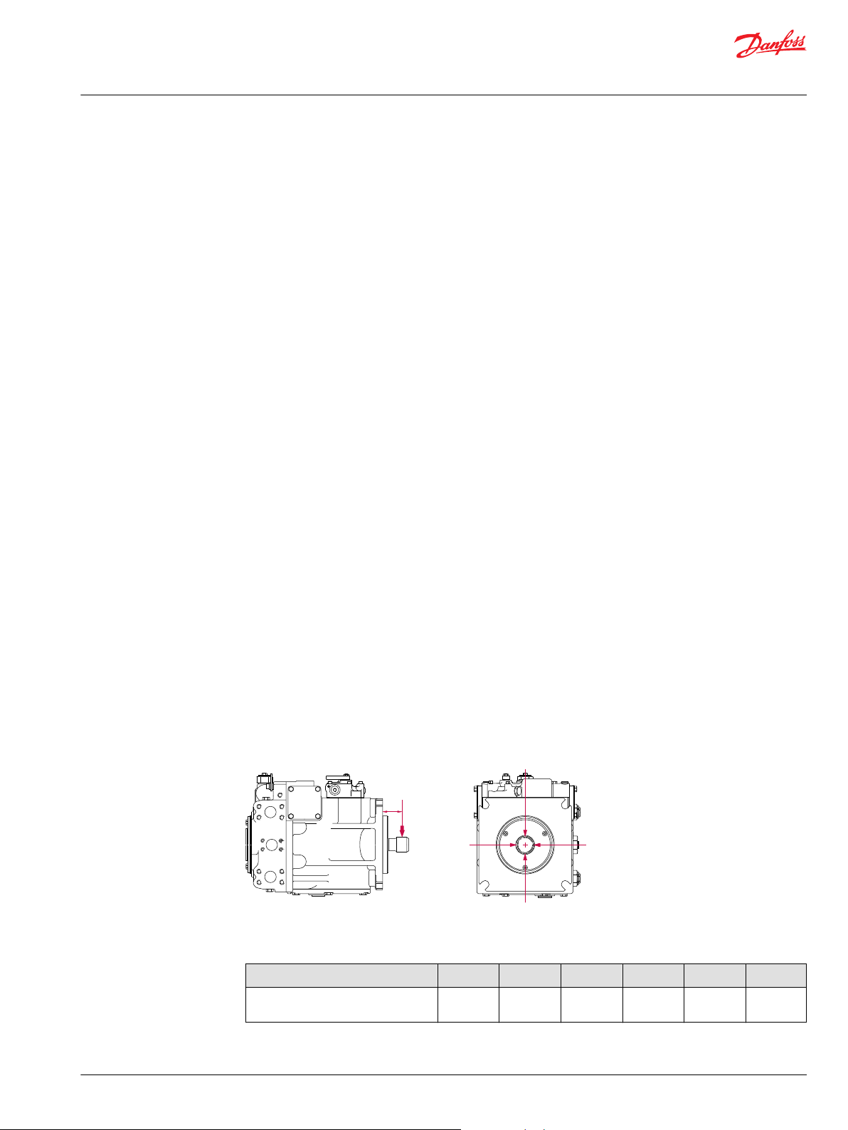
Applications with external shaft loads
External loads are found in applications where the pump is driven with a side/thrust load (belt drive or
gear drive) as well as in installations with misalignment and improper concentricity between the pump
and drive coupling. All external loads act to reduce bearing life.
In applications where you cannot avoid external radial shaft loads, orient the load to 0° or 180° position.
Use tapered output shafts or clamp-type couplings where radial shaft loads are present.
In addition, external thrust loads can reduce bearing life in systems with low delta pressure or in
combination with external radial loads/bending moments.
Re = Me / L
Me = Shaft moment
L = Flange distance
Re = External force
Radial load position
Maximum allowable external shaft load
Parameter 055 075 100 130 180 250
©
Danfoss | March 2022 BC152886483413en-000910 | 17
External moment (Me)
N•m [lbf•in]
* no tapered shaft available
101
[893]
118
[1043]
126
[1114]
140
[1238]
* *
Page 18

Outp ut f ow Q = (l/min..)
Inp ut torque M = (N•m)
Inp ut power P = = (kW)
SI units Vg= Displacement pe r revolution
(cm3/rev)
∆p = pO- pi(system pressure)
(bar)
n = Speed (min-1(rpm))
ηv= Volumetric eff ciency
ηm= Mechanical eff ciency
ηt= Overall effciency (ηv• ηm)
Vg• n • η
v
1000
Vg• ∆p
20 • π • η
m
Q •∆p
600 • η
t
M • n • π
30 000
g
= Displacement pe r revolution
(in3/rev)
∆p = pO- pi(system pressure)
(psi)
n = Speed (min-1(rpm))
ηv= Volumetric eff ciency
ηm= Mechanical eff ciency
ηt= Overall effciency (ηv• ηm)
Outp ut f ow Q = (US gal/min..)
Inp ut torque M = (lbf•in)
Inp ut power P = = (hp)
Vg• n • η
v
231
Vg• ∆p
2 •π • η
m
Q •∆p
1714 • η
t
M • n • π
198 000
Technical Information
Series 90 Axial Piston Pumps
System Design Parameters
If continuous applied external radial loads are 25% of the maximum allowable or more or thrust loads/
bending moments known to occur, contact your Danfoss representative for an evolution of bearing life.
Avoid external thrust loads in either direction.
Understanding and Minimizing System Noise
Noise is transmitted in fluid power systems in two ways: as fluid borne noise, and structure borne noise.
Fluid-borne noise (pressure ripple or pulsation) is created as pumping elements discharge oil into the
pump outlet. It is affected by the compressibility of the oil, and the pump's ability to transition pumping
elements from high to low pressure. Pulsations travel through the hydraulic lines at the speed of sound
(about 1400 m/s [4600 ft/sec] in oil) until there is a change (such as an elbow) in the line. Thus, amplitude
varies with overall line length and position.
Structure born noise is transmitted wherever the pump casing connects to the rest of the system. The
way system components respond to excitation depends on their size, form, material, and mounting.
System lines and pump mounting can amplify pump noise.
Follow these suggestions to help minimize noise in your application:
Use flexible hoses.
•
Limit system line length.
•
If possible, optimize system line position to minimize noise.
•
If you must use steel plumbing, clamp the lines.
•
If you add additional support, use rubber mounts.
•
Test for resonants in the operating range; if possible avoid them.
•
Sizing Equations
The following equations are helpful when sizing hydraulic pumps. Generally, the sizing process is
initiated by an evaluation of the machine system to determine the required motor speed and torque to
perform the necessary work function. Refer to Selection of drive line components, BC157786484430, for a
more complete description of hydrostatic drive line sizing. First, the motor is sized to transmit the
maximum required torque. The pump is then selected as a flow source to achieve the maximum motor
speed.
18 | © Danfoss | March 2022 BC152886483413en-000910
Page 19
First stageSecond stage
Third
stage
P108 511E
L1
L2
L3
F2 F1
F3
R
= g • GR(W1L1+ W2L2+ ... + WnLn)
S
= g • GS(W1L1+ W2L2+ ... + WnLn)
R
= Rated load moment N•m
S
= Shock load mome nt N•m
2
R
= Calculation factor for rated (vibratory) acceleration (G’s)*
S
= Calculation factor for maximum shock acceleration (G’s)*
MR= GR(W1L1+ W2L2+ ... + WnLn)
MS= GS(W1L1+ W2L2+ ... + WnLn)
Based on US units
W = Weight of pump [lb]
L = Distance from mounting f ang e [in]
to pump center of gravity
Where:
MR= Rated load moment N•m
MS= Shock load mome nt N•m
Technical Information
Series 90 Axial Piston Pumps
System Design Parameters
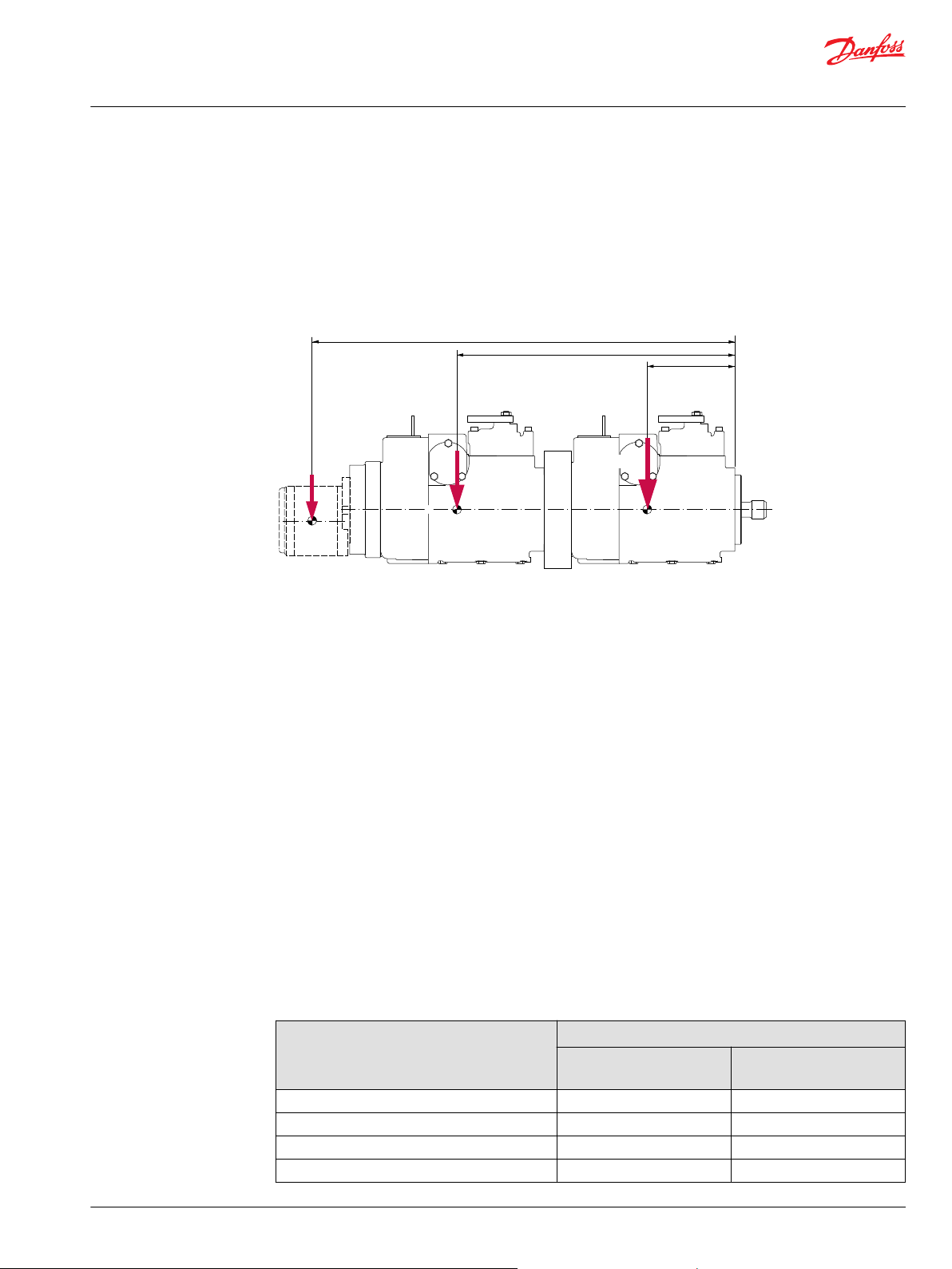
Mounting Flange Loads
Adding tandem mounted auxiliary pumps and/or subjecting pumps to high shock loads may result in
excessive loading of the mounting flange.
Applications which experience extreme resonant vibrations or shock may require additional pump
support. The overhung load moment for multiple pump mounting may be estimated using the formula
below.
Overhung load example
Estimated maximum and rated acceleration factors for some typical applications are shown in the table
below.
Use these values for a rough load estimation in the absence of specific data.
Typical G loads for various applications
Application Calculation factor
©
Danfoss | March 2022 BC152886483413en-000910 | 19
Skid Steer Loader 8 15-20
Trencher (rubber tires) 3 8
Asphalt Paver 2 6
Windrower 2 5
Rated (vibratory)
acceleration G
R
Maximum (shock)
acceleration G
S
Page 20
Technical Information
Series 90 Axial Piston Pumps
System Design Parameters
Typical G loads for various applications (continued)
Application Calculation factor
Aerial Lift 1.5 4
Turf Care Vehicle 1.5 4
Vibratory Roller 6 10
T000 165E
Allowable overhung load moment values are shown in the following table.
Allowable overhung load moments
Frame size Rated moment (MR) Shock load moment (MS)
055 1580 14 000 5650 50 000
075 1580 14 000 5650 50 000
100 1580 14 000 5650 50 000
130 3160 28 000 10 730 95 000
180 6070 54 000 20 600 182 000
250 6070 54 000 20 600 182 000
Rated (vibratory)
acceleration G
N•m lbf•in N•m lbf•in
R
Maximum (shock)
acceleration G
S
20 | © Danfoss | March 2022 BC152886483413en-000910
Page 21
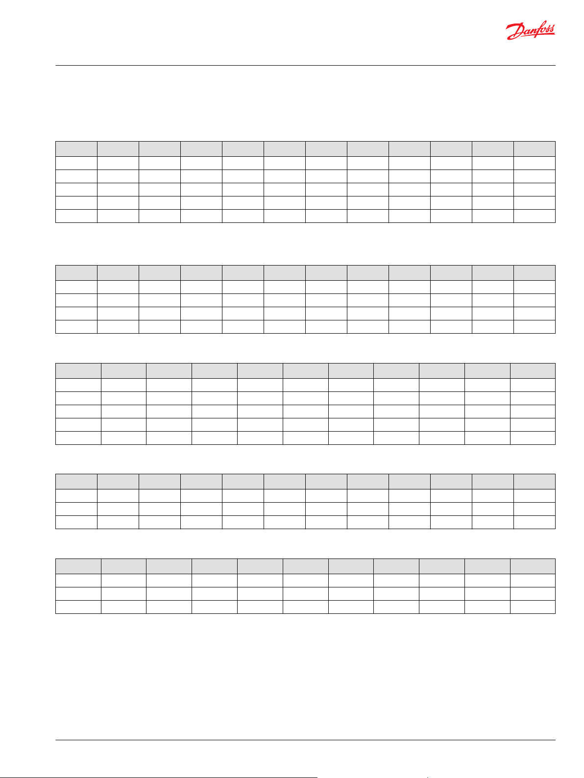
R Size M P J G N F L H T W Y Z K
S90
Technical Information
Series 90 Axial Piston Pumps
Master Model Code
Series 90 Master Model Code Breakdown
S90 Rotation and Size Options
R – Rotation
Code Description 055 075 100 130 180 250
R Right hand [CW] X X X X X X
L Left hand [CCW] X X X X X X
Size
055 55 cc [3.36 in3] max displacement per revolution X
075 75 cc [4.58 in3] max displacement per revolution X
100 100 cc [6.10 in3] max displacement per revolution X
130 130 cc [7.93 in3] max displacement per revolution X
180 180 cc [10.98 in3] max displacement per revolution X
250 250 cc [15.26 in3] max displacement per revolution X
©
Danfoss | March 2022 BC152886483413en-000910 | 21
Page 22

Technical Information
Series 90 Axial Piston Pumps
Master Model Code
S90 Control Options
M – Controls
Code Description 055 075 100 130 180 250
CA Cover plate without feedback link, no control X X X X X X
DC 3 position F-N-R solenoid control (12V, DC) DIN
connector
DD 3 position F-N-R solenoid control (24V, DC) DIN
connector
HF HDC 2, std. porting, 3, 0-11 bar [44-160 psi] X X X X X X
KA EDC, MS connector, std. porting, dual coil (14-85 mA) X X X X X X
KN EDC, MS connector, std. porting, 643 Ohm single coil
(4-20 mA)
KT EDC DEUTSCH connector, std. porting, dual coil (14-85
mA)
KP EDC, Weatherpack connector, std. porting, dual coil
(14-85 mA)
MA MDC X X X X X X
MB MDC with neutral start switch X X X X X X
FA NFPE control with 12V Amp connector; proportional
solenoid with pressure reducing valve (25 bar)
FB NFPE control with 24V Amp connector; proportional
solenoid with pressure reducing valve (25 bar)
FC NFPE control with 12V Amp connector; proportional
solenoid with pressure reducing valve (32 bar)
FD NFPE control with 24V Amp connector; proportional
solenoid with pressure reducing valve (32 bar)
FG NFPE control with 12V Amp connector; proportional
solenoid with pressure reducing valve (32 bar) fast
response
FH NFPE control with 24V Amp connector; proportional
solenoid with pressure reducing valve (32 bar) fast
response
FK NFPE control with 12V AMP connector; proportional
solenoid with pressure reducing valve (25 bar)
FL NFPE control with 24V AMP connector; proportional
solenoid with pressure reducing valve (25 bar)
FM NFPE control with 12V Amp connector; proportional
solenoid with pressure reducing valve (32 bar) fast
response
FN NFPE control with 24V Amp connector; proportional
solenoid with pressure reducing valve (32 bar)
X X X X X
X X X X X X
X X X X X X
X X X X X X
X X X X X X
X X
X X X
X X
X X
X X X X
X X X X
X
X
X
X
22 | © Danfoss | March 2022 BC152886483413en-000910
Page 23
Technical Information
Series 90 Axial Piston Pumps
Master Model Code
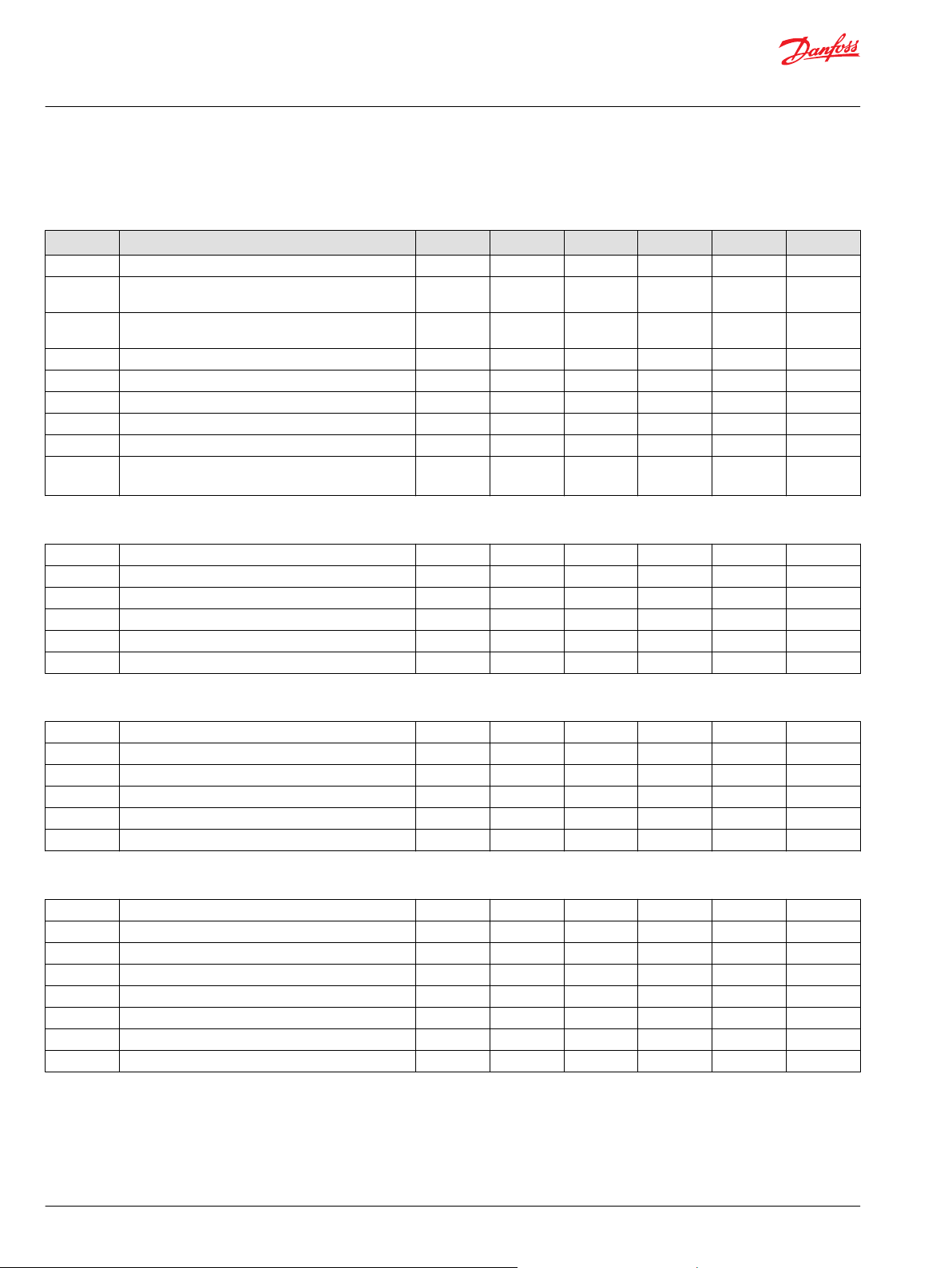
S90 Pressure, Aux Mounting, Ports, Filtration, Displacement Limitation
P – High pressure regulation
Code Description 055 075 100 130 180 250
1 Pressure limiter for port A and B (140-450 bar) X X X X X X
2 High pressure relief valves for port A and B (90-450
bar)
J – Auxiliary Mounting Pad
AB SAE-A with sealed cover, 9 teeth coupling X X X X X X
BB SAE-B with sealed cover, 15 teeth coupling X X X X X X
BC SAE-B with sealed cover, 13 teeth coupling X X X X X X
CD SAE-C with sealed cover, 4 bolt adapter, 14 teeth
coupling
DE SAE-D with sealed cover, 13 teeth coupling X X X
EF SAE-E with sealed cover, 13 teeth coupling X X
NN No auxiliary mounting pad X X X X X X
X X X X X X
X X X X X X
G – Endcap ports
60 Side ports X X X
80 Twin ports X X X X X X
N – Filtration
D External charge pump X X X X X X
L Pressure integral (long filter) X X X X
P Pressure integral (short filter) X X X X
R Remote pressure X X X X
T Remote pressure with SAE 1 1/16 thread ports for
high flow
S Suction filtration X X X X X X
X X
F – Displacement limitation
C No limiters (180 cc only) X
M Limitation on both sides (180 cc only) X
3 No limiters X X X X X
4 Limitation on both sides X X X X X
7 No limiters, special servo cylinder side 1 with hard
spring (for pumps with NFPE control only)
X X X X X
©
Danfoss | March 2022 BC152886483413en-000910 | 23
Page 24
Technical Information
Series 90 Axial Piston Pumps
Master Model Code
S90 Shaft and Charging System
L – Shaft Options
Code Description 055 075 100 130 180 250
C6 Splined shaft, 21 teeth, 16/32 pitch X X X
C7 Splined shaft, 23 teeth, 16/32 pitch X X
C8 Splined shaft, 27 teeth, 16/32 pitch X X X
F1 Splined shaft, 13 teeth, 8/16 pitch X X X X
S1 Splined shaft, 14 teeth, 12/24 pitch X X X
G1 Splined shaft, 25 teeth, 20/40 pitch X X
T1 Tapered shaft, 34.925 mm diameter X X
T6 Tapered shaft, 38.1 mm diameter X X
T8 Tapered shaft, 25.4 mm diameter
T4 Tapered shaft, 44.45 mm diameter X
H – Charging System
B 11 cc/rev nominal flow X
C 14 cc/rev nominal flow X X
D 17 cc/rev X X X
E 20 cc/rev X X
F 26 cc/rev X X
H 34 cc/rev X X
J 47 cc/rev X X
K 65 cc/rev X
L External charge pump with internal charge pressure
relieve valve for units with auxiliary mounting pad
N External charge pump with internal charge pressure
relieve valve for units without auxiliary mounting pad
X X X X X X
X X X X X
24 | © Danfoss | March 2022 BC152886483413en-000910
Page 25
Technical Information
Series 90 Axial Piston Pumps
Master Model Code
S90 Control Orifice Options
T – Control Orifice Options for MDC
Code Inlet P Drain TA Drain TB Servo A Servo B 055 075 100 130 180 250
00 None 1.6
03 0.81 1.6
05 1.37 1.6
*
*
*
C5 0.81 1.4 1.4 None None X X X X X X
C6 1.37 1.4 1.4 None None X X X X X X
*
No orifice installed in control,orifice hole in control spool
T – Control Orifice Options for EDC
Code Inlet P Drain TA Drain TB Servo A Servo B 055 075 100 130 180 250
00 None 1.3 1.3 None None X X X X X X
03 0.81 1.3 1.3 None None X X X X X X
05 1.37 1.3 1.3 None None X X X X X X
33 0.81 None None None None X X X X X X
1.6
1.6
1.6
*
*
*
None None X X X X X X
None None X X X X X X
None None X X X X X X
T – Control Orifice Options for FNR
Code Inlet P Drain T Servo A Servo B 055 075 100 130 180 250
G1 None 1.2 None None X X X X X X
G4 0.46 1.2 None None X X X X X X
G8 0.66 1.2 None None X X X X X X
GB 0.81 1.2 None None X X X X X X
GD 1.57 1.2 None None X X X X X X
T – Control Orifice Options for HDC
Code Inlet P Drain TA Drain TB Servo A Servo B 055 075 100 130 180 250
00 None 1.3 1.3 None None X X X X X X
003 0.81 1.3 1.3 None None X X X X X X
005 1.37 1.3 1.3 None None X X X X X X
T – Control Orifice Options for NFPE
Code Inlet P Drain T Servo A Servo B 055 075 100 130 180 250
B1 None 1.5 None None X X X X X X
B2 None None 1.2 1.2 X X X X X X
B6 None None None None X
©
Danfoss | March 2022 BC152886483413en-000910 | 25
Page 26
Technical Information
Series 90 Axial Piston Pumps
Master Model Code
S90 Special Hardware and Pressure Settings
W – Special Hardware Features
Code Description 055 075 100 130 180 250
EEG Speed ring, no sensor, CP30 + 4.3° valve plate X X X X
EFC Speed sensing, Turck connector (KPP x 156), CP15 +
EFI Speed sensing Turck connector (KPP x 156) CP30 +
FAC Nest T-bar springs CP15 + 1.5° valve plate X X X X X
FAD Nested T-bar springs CP15 + 0.5° valve plate X X X X
GBA CP15 + 0.5° valve plate X X X X
GCA CP15 + 1.5° valve plate X X X X X
GLA CP30 + 4.3° valve plate, CP30 valve plug X X X X X X
NNN
1.5° valve plate
X X X X X X
4.3° valve plate
180cc: CP15 + 0.5° valve plate
250cc: CP15 + 1.5° valve plate, nested T-bar springs
Y – High Pressure Setting A
26 260 bar X X X X X X
32 320 bar X X X X X X
35 350 bar X X X X X X
38 380 bar X X X X X X
40 400 bar X X X X X X
42 420 bar X X X X X X
X X X
X X
Z – High Pressure Setting B
26 260 bar X X X X X X
32 320 bar X X X X X X
35 350 bar X X X X X X
38 380 bar X X X X X X
40 400 bar X X X X X X
42 420 bar X X X X X X
K – Charge Pressure Setting
20 20 bar X X X X X X
22 22 bar X X X X X X
24 24 bar X X X X X X
26 26 bar X X X X X X
28 28 bar X X X X X X
30 30 bar X X X X X X
32 32 bar X X X X X
34 34 bar X X X X X
26 | © Danfoss | March 2022 BC152886483413en-000910
Page 27

W
1 2
Not connected
Voltage between terminals 1 and 2
DANFOSS
mating parts kit
Part No. K09129
Solenoid plug face for DIN 43650 connector
"0"
Voltage VDC
Displacement
100 %
b
100 %
-b
P102 023
M5
a
b
M4
T
P
P102021
Technical Information
Series 90 Axial Piston Pumps
Control Features
3-Position (FNR) Electric Control - DC, DD
The 3-Position (FNR) control uses an electric input signal to switch the pump to a full stroke position. To
use the FNR control in a PLUS+1 Guide application, download HWD file 10106826 from
www.Danfoss.com/PLUS+1.
Warning
Avoid designing a system which places the swashplate into full stroke when control operation is blocked
by contamination.
Solenoid connector
Pump displacement vs. electrical signal
3-position electric control hydraulic schematic
©
Danfoss | March 2022 BC152886483413en-000910 | 27
Solenoid Data
Code Voltage Current Connector
DC 12 Vdc 340 mA DIN 46350
DD 24 Vdc 170 mA DIN 46350
Page 28

A
P108 495E
B
W
Technical Information
Series 90 Axial Piston Pumps
Control Features
Response time
The time required for the pump to change from zero to full flow (acceleration), or full flow to zero
(deceleration), is a function of the size of the orifice, the charge pressure, valve plates and other vehicle
dynamics.
A range of orifice sizes are available for the Series 90 FNR Control to assist in matching the rate of
swashplate response to the acceleration and deceleration requirements of the application. Testing
should be carried out to determine the proper orifice selection for the desired response. For more
information regarding response time for individual orifices, please contact your Danfoss representative.
Pump output flow direction vs. control signal
Input shaft rotation CW CCW
Signal at solenoid A B A B
Port A flow (M1) Out In In Out
Port B flow (M2) In Out Out In
Servo cylinder (side) M5 (2) M4 (1) M5 (2) M4 (1)
Warning
Avoid designing a system which puts the swashplate into full stroke when control operation is blocked
by contamination.
Electric Displacement Control (EDC), Options KA, KP, KT
The electric displacement control uses an electrohydraulic Pressure Control Pilot (PCP) valve to control
the pilot pressure. The PCP converts an electrical input signal to a hydraulic input signal to operate a 4way servo valve, which ports hydraulic pressure to either side of a double acting servo piston. The servo
piston tilts the cradle swashplate, thus varying the pump's displacement from full displacement in one
direction to full displacement in the opposite direction.
The control has a mechanical feedback mechanism which moves the servo valve in relation to the input
signal and the angular position of the swashplate. The electrical displacement control is designed so the
angular rotation of the swashplate (pump displacement) is proportional to the electrical input signal. Due
to normal operating force changes, the swashplate tends to drift from the position preset by the machine
operator. Drift, sensed by feedback linkage system connecting the swashplate to the control valve, will
activate the valve and supply pressure to the servo piston, maintaining the swashplate in its preset
position.
Features and Benefits
The electric displacement control is a high gain control: With only a small change of the input current,
•
the servo valve moves to a full open position thus porting maximum flow to the servo cylinder.
Oil filled PCP case lengthens control life by preventing moisture ingression and dampening
•
component vibrations.
All electrical displacement controls are equipped with dual coil PCPs. The user has the option of using
•
a single coil or both coils (in series or parallel).
28 | © Danfoss | March 2022 BC152886483413en-000910
Page 29

M5 M4
T
P
X2 X1
P102 024E
Feedback fr om
swashpla te
T
P
TM4 M5
P C P
X2
X1
P102 025
Technical Information
Series 90 Axial Piston Pumps
Control Features
•
•
•
Benefits
•
•
Electric displacement control schematic
Internal mechanical stops on the servo valve allow rapid changes in input signal voltages without
damaging the control mechanism.
Precision parts provide repeatable accurate displacement settings.
The swashplate is coupled to a feedback mechanism. The control valve drains the ends of the servo
piston when an electric input signal is not present.
Pump returns to neutral after prime mover shuts down
Pump returns to neutral if external electrical input signal fails or if there is a loss of charge pressure
Cross-section
To use the EDC control in a PLUS+1 Guide application, download HWD file 10106626 from
www.Danfoss.com/Plus1.
©
Danfoss | March 2022 BC152886483413en-000910 | 29
Page 30

7 mA with 0.25 Vdc
43 mA with 1.55 Vdc
Clockwise
Clockwise
Counterclockwise
Counterclockwise
Start Current
Full Stroke Current
Start Current
Full Stroke Current
T
F
A
H
S
P
M
U
P
N
O
I
T
A
T
O
R
L
A
C
I
R
T
C
E
L
E
S
T
N
E
M
E
R
I
U
Q
E
R
A or C
B or D
A and C A
D
One of Dual Coils
Dual Coils in Parallel
Dual Coils in Series
A
B
B
A
Produces
Flow Out of
Pump Port
A or C
A and C
A
B or D
B and D
D
B and D
14 mA with 0.13 Vdc
85 mA with 0.75 Vdc
A B C D
+ phasing to terminals
B C DA
+ phasing to terminals
B C DA
+ phasing to terminals
A/B 14 mA
± 3 mA
A/B 85 mA
± 11 mA
C/D 14 mA
± 3 mA
C/D 85 mA
± 11 mA
P108 497E
with 1.7 Vdc
with 0.3 Vdc
with 0.23 Vdc
with 1.36 Vdc
W
A
B
D
C
Danfoss
mating parts kit
Part no. K01588
Ident No. 615062
B
C
D
Danfoss
mating parts kit
Part no. K03384
(female terminals)
A
Technical Information
Series 90 Axial Piston Pumps
Control Features
Electrical Characteristics
The EDC is designed to be controlled from a DC current source or voltage source. Pulse width modulation
(PWM) is not required. If a PWM signal is used to carry frequency greater than 200 Hz, do not use a pulse
current of more than 120% of that required for full output.
Control signal requirements
Recommended PWM signal is 200 Hz, avoid exceeding 440 Hz.
Warning
Maximum input current under any condition: 250 mA
PWM frequency: 200 Hz
Coil resistance at 24°C [75°F]:
A-B coil 20 Ω
C-D coil 16 Ω
MS connector (option KA) MS 3102C-14S-2P
Packard® Weather-Pack (option KP) 4-way shroud connector
30 | © Danfoss | March 2022 BC152886483413en-000910
Page 31

"0"
Current mA
Displacement
100 %
a b
-b -a
100 %
P102 026E
4 pin Deutsch® Plug DT Series Connector
1
3
2
4
P108 815E
Danfoss
mating parts kit
Part no. K23511
(D)
(C)
(A)
(B)
Technical Information
Series 90 Axial Piston Pumps
Control Features
Pump displacement vs. control current
Deutsch DT Series connector (option KT)
Response time
The time required for the pump output flow to change from zero to full flow (acceleration) or full flow to
zero (deceleration) is a function of the size of the orifice in the control flow passage, charge pressure,
valve plate and other vehicle dynamics.
A range of orifice sizes is available for the Series 90 Electric Displacement Control to assist in matching the
rate of swashplate response to the acceleration and deceleration requirements of the application. Testing
should be carried out to determine the proper orifice selection for the desired response.
For more information regarding response times for individual orifices, contact your Danfoss
representative.
Pump output flow direction vs. control current
EDC using a single coil or dual coils in parallel (A and C common, B and D common)
Input shaft rotation CW CCW
Positive current to term A or C B or D A or C B or D
Port A flow (M1) Out In In Out
Port B flow (M2) In Out Out In
Servo cylinder (side) M5 (2) M4 (1) M5 (2) M4 (1)
EDC using a dual coil in series (B and C common)
Input shaft rotation CW CCW
Positive current to term A D A D
Port A flow (M1) Out In In Out
©
Danfoss | March 2022 BC152886483413en-000910 | 31
Page 32

W
W
Pump Phasing With EDC Manual Operator (MOR)
Pump
MOR
Rotation
Pump Flow
troP tuOnoitatoR
CW
Towards Connector
Towards Connector
B
AWCC
P108 498E
P108 496E
EDC Second Stage
Manual Over Ride (MOR)
EDC Pilot Stage (PCP)
W
Technical Information
Series 90 Axial Piston Pumps
Control Features
EDC using a dual coil in series (B and C common) (continued)
Port B flow (M2) In Out Out In
Servo cylinder (side) M5 (2) M4 (1) M5 (2) M4 (1)
Refer to Installation Drawings for port locations.
For further information on EDC controls, refer to Electrical Displacement Control For Series 90 Pumps,
AN152886482128.
Manual Over Ride (MOR)
EDC controls are available with a Manual Over Ride (MOR) which is intended for temporary actuation of
the control to aid in pump diagnostics.
Using the MOR to control the pump will not result in proportional control.
Refer to the control flow table in the size specific technical information manual for the relationship of
solenoid to direction of flow.
Warning
The vehicle must always be in a safe condition (i.e. vehicle lifted off the ground) when using the MOR
function. The MOR lever has a must be manually actuated to be engaged. Moving the plunger
mechanically moves the pilot stage armature which allows the pump to go on stroke. The MOR should be
engaged anticipating a full stroke response from the pump.
Warning
Warning
Unintended MOR operation will cause the pump to go into stroke.
32 | © Danfoss | March 2022 BC152886483413en-000910
Page 33

W
M5 M4
T
P
Feedback
from
swashplat e
X2
X1
P102029
Technical Information
Series 90 Axial Piston Pumps
Control Features
Hydraulic Displacement Control (HDC), Option HF, HS
Warning
Avoid designing a system which puts swashplate into full stroke when control operation is blocked by
contamination.
Operation
The hydraulic displacement control uses a hydraulic input signal to operate a 4-way servo valve, which
ports hydraulic pressure to either side of a double acting servo piston. The servo piston tilts the cradle
swashplate, thus varying the pump's displacement from full displacement in one direction to full
displacement in the opposite direction.
The control has a mechanical feedback mechanism which moves the servo valve in relation to the input
signal and the angular rotation of the swashplate. The hydraulic displacement control is designed so the
angular position of the swashplate (pump displacement) is proportional to the hydraulic input signal
pressure. Due to normal operating force changes, the swashplate tends to drift from the position preset
by the machine operator. Drift, sensed by feedback linkage system connecting the swashplate to the
control valve, activates the valve to supply pressure to the servo piston, maintaining the swashplate in its
preset position.
Features and Benefits
The hydraulic displacement control is a high gain control: With only small change of the input signal,
•
the servo valve moves to a full open position porting maximum flow to the servo cylinder.
Internal mechanical stops on the servo valve allow rapid changes in input signal pressure without
•
damaging the control mechanism.
Precision parts provide repeatable, accurate displacement settings with a given input signal.
•
The swashplate is coupled to a feedback mechanism. The control valve drains the ends of the servo
•
piston when an input signal is not present.
Benefits:
Simple - low cost design.
•
Pump returns to neutral after prime mover shuts down.
•
Pump returns to neutral if there is a loss of input signal pressure or if there is a loss of charge pressure.
•
Hydraulic displacement control schematic
©
Danfoss | March 2022 BC152886483413en-000910 | 33
Page 34

T
M4 P
M5
T
P102 030
X1 X2
W
"0"
Signal pressure
Displacement
100 %
a b
-b -a
100 %
P102 031E
Technical Information
Series 90 Axial Piston Pumps
Control Features
Cross-section
Maximum allowable signal pressure is 60 bar [870 psi]. Exceeding allowable signal pressure will cause
damage to the control.
Response time
The time required for the pump output flow to change from zero to full flow (acceleration) or full flow to
zero (deceleration) is a function of the size of the orifice in the control flow passage, charge pressure,
valve plates and other vehicle dynamics.
A range of orifice sizes are available for the Series 90 hydraulic displacement control to assist in matching
the rate of swashplate response to the acceleration and deceleration requirements of the application.
Testing should be carried out to determine the proper orifice selection for the desired response.
For more information regarding response time for individual orifices, please contact your Danfoss
representative.
Pump displacement vs. signal pressure
Warning
Hydraulic signal pressure range*
HF HS
a
b
Pump output flow direction vs. control pressure
3 ± 0.5 bar 6 ± 0.5 bar
11 ± 0.5 bar 18 ± 0.5 bar
Pump output flow direction vs. control pressure
Input shaft rotation CW CCW
Control pressure to port X1 X2 X1 X2
Port A flow (M1) Out In In Out
34 | © Danfoss | March 2022 BC152886483413en-000910
Page 35

W
M4
M5
T P
Feedback
from
swashplate
A – 0 – B
Switch
Neutral
Start
P102 035E
Technical Information
Series 90 Axial Piston Pumps
Control Features
Pump output flow direction vs. control pressure (continued)
Input shaft rotation CW CCW
Port B flow (M2) In Out Out In
Servo cylinder (side) M5 (2) M4 (1) M5 (2) M4 (1)
Refer to Installation Drawings, for port locations.
Manual Displacement Control (MDC), Options MA, MB
Warning
Avoid designing a system which puts swashplate into full stroke when control operation is blocked by
contamination.
The manual displacement control converts a mechanical input signal to a hydraulic signal that tilts the
cradle swashplate through an angular rotation varying the pump's displacement from full displacement
in one direction to full displacement in the opposite direction.
The manual displacement control has a mechanical feedback mechanism which moves a servo valve in
the proper relationship to the input signal and the angular position of the swashplate. The control is
designed so that the angular rotation of the swashplate is proportional to the mechanical input signal.
The control is designed with an internal override mechanism which allows the mechanical input to be
moved at a faster rate than the movement of the swashplate without damage to the control.
Features and benefits
Precision parts provide repeatable, accurate displacement settings with a given input signal.
•
The manual displacement control is a high gain control: With only small movement of the control
•
handle (input signal), the servo valve moves to full open position porting maximum flow to the servo
cylinder. This is a high response system with low input force.
The integral override mechanism allows rapid changes in input signal without damaging the control
•
mechanism.
Precision parts provide repeatable, accurate displacement settings with a given input signal.
•
The double-acting servo piston is coupled to a spring centering mechanism. The servo control valve is
•
spring centered such that with no input signal the servo valve is open centered and thus no fluid is
ported to the servo cylinder.
Benefits:
- Pump returns to neutral after prime mover shuts down.
•
- Pump returns to neutral if external control linkage fails at the control handle or if there is a loss of
•
charge pressure.
Manual displacement control schematic
©
Danfoss | March 2022 BC152886483413en-000910 | 35
Page 36

T
M5 P
M4
T
Control handle input signal
P102 033E
0
Lever rotation
A
Displacement
100 %
a
-a
100 %
B
-b
b
P102 034E
-35 max.
35 max.
Technical Information
Series 90 Axial Piston Pumps
Control Features
Cross-section
External control handle requirements
•
•
•
•
Pump displacement vs. control lever rotation
Torque required to move handle to maximum displacement is 0.68 to 0.9 N•m [6 to 8 lbf•in].
Torque required to hold handle at given displacement is 0.34 to 0.57 N•m [3 to 5 lbf•in].
Torque required to overcome the override mechanism is 1.1 to 2.3 N•m [10 to 20 lbf•in] with the
maximum torque required for full forward to full reverse movement.
Maximum allowable input torque is 17 N•m [150 lbf•in].
Control lever rotation range
a 0,5° - 4.5°
b 24° - 30°
Volumetric efficiencies of the system will have impacts on the start- and end input- commands.
Response Time
The time required for the pump output flow to change from zero to full flow (acceleration) or full flow to
zero (deceleration) is a function of the size of the orifice and charge pressure in the control, charge
pressure, valve plates and other vehicle dynamics.
A range of orifice sizes is available for the Series 90 manual displacement control to assist in matching the
rate of swashplate response to the acceleration and deceleration requirements of the application. Testing
should be carried out to determine the proper orifice selection for the desired response. For more
information regarding response time for individual orifices, please contact your Danfoss representative.
36 | © Danfoss | March 2022 BC152886483413en-000910
Page 37

"B"
"A"
30°
minimum
30°
minimum
Neutral
position
Maximum
displacement
Maximum
displacement
P108 550E
Technical Information
Series 90 Axial Piston Pumps
Control Features
Pump output flow direction vs. control handle rotation
MDC handle rotation parameters
Pump output flow direction vs. control handle rotation
Input shaft rotation CW CCW
Handle rotation A B A B
Port A flow (M1) Out In In Out
Port B flow (M2) In Out Out In
Servo cylinder (side) M5 (2) M4 (1) M5 (2) M4 (1)
Refer toInstallation Drawings for handle connection requirements
Neutral start switch (NSS) for MDC
The neutral start switch is an optional feature available with the MDC. When connected properly with the
vehicle’s electrical system, the neutral start switch ensures that the prime mover can start only when the
control is in neutral position.
Non Feedback Proportional Electric Control (NFPE)
The Non Feedback Proportional Electric (NFPE) control is an electrical automotive control in which an
electrical input signal activates one of two proportional solenoids that port charge pressure to either side
of the pump servo cylinder. The NFPE control has no mechanical feedback mechanism.
The pump displacement is proportional to the solenoid signal current, but it also depends upon pump
input speed and system pressure. This characteristic also provides a power limiting function by reducing
the pump swashplate angle as system pressure increases.
Control response
Series 90 controls are available with optional control passage orifices to assist in matching the rate of
swashplate response to the application requirements (e.g. in the event of electrical failure). Software
ramp or rate limiting should be used to control vehicle response in normal operation. The time required
for the pump output flow to change from zero to full flow (acceleration) or full flow to zero (deceleration)
is a net function of spool porting, orifices, charge pressure, valve plates and other vehicle dynamics. A
swashplate response table is available for each frame indicating available swashplate response times.
Testing a prototype system to verify the software and orifice selection provide the desired response.
Series 90 pumps have many orificing combinations, however, software is the best means of controling
the swashplate response in normal operating conditions. Mechanical servo orifices should be used only
for fail-safe return to neutral in the event of an electrical failure.
©
Danfoss | March 2022 BC152886483413en-000910 | 37
Page 38

"0"
Signal Current
mA(DC)
a b c
a
b
c
Displacement
100 %
100 %
NFPE control
∆p = 300 bar
∆p = 300 bar
∆p = 0 bar
∆p = 0 bar
P003 187E
B
A
M5
M4
M3
M1
M2
L1
S
L2
M6
P003 174
Technical Information
Series 90 Axial Piston Pumps
Control Features
Pump Displacement vs. Input Signal
NFPE Schematic
NFPE control used with a Danfoss microcontroller
Creep mode
•
Two automotive control ramps via mode switch
•
Engine overspeed protection
•
Electric control
•
Anti-stall function
•
Smooth operation
•
Electronic ramp control is superior to hydraulic control with orifices
•
Input signal requirements
The NFPE control requires a pulse-width-modulated (PWM) input current to optimize performance. The
38 | © Danfoss | March 2022 BC152886483413en-000910
recommended PWM frequency is 100 Hz. The minimum PWM frequency is 80 Hz.
Page 39

P108 500E
2
1
Amp Junior Power Timer
2 Pin Connector
(Male Terminal)
Mating Connector:
Danfoss
Identification Number
10102040
Technical Information
Series 90 Axial Piston Pumps
Control Features
Solenoid data
Option FA FB FC FD FK FL FM FN FG FH
Frame Size 55cc, 100cc 75cc 75cc, 100cc, 130cc,
180cc
Voltage [V] 12 24 12 24 12 24 12 24 12 24
32Working Pressure [Bar] 25 25 32 32 25 25 25 32 32 32
Maximum Current [mA] 1500 750 1500 750 1500 750 1500 750 1500 750
Start Current [mA] 440 220 440 220 440 220 440 220 440 220
End Current [mA] 1290 645 1280 645 1290 645 1290 645 1290 645
Coil Resistance [Ohm] 4.72±5% 20.8±5% 5.3±5% 21.2±5% 4.72±5% 4.72±5% 4.72±5% 4.72±5% 4.98±3% 20.6±3%
PWM Range [Hz] 70-200 70-200 70-200
PWM Prefered [Hz] 200 200 200
Protection Class up to IP6K6/IPX7/IPX9K up to IP6K6/IPX7/IPX9K IP65 DIN 40050
Connector Amp Junior Timer AMP Junior Timer Amp Junior Timer
* PWM Signal Required for Optimum Control Performance.
To use the NFPE control in a PLUS+1 application, download the appropriate file from www.Danfoss.com/
PLUS+1.
NFPE pump displacement vs. input signal
Shaft rotation CW CCW
Active solenoid 1 and A 2 and B 1 and A 2 and B
Port A flow Out In In Out
Port B flow In Out Out In
Servo cylinder M5 M4 M5 M4
The NFPE control uses an AMP® Junior Power Timer connector. The solenoids are compatible with
Danfoss microcontrollers and joysticks.
©
Danfoss | March 2022 BC152886483413en-000910 | 39
Page 40

M
B
L2
M2
M1
M4
M5
M3
A
S
Charge
pressure
relief valve
Multifunction valve
Multifunction valve
To control
Servo piston
Servo piston
Port A
Port B
C
Bypass hex
adjustment
P102 007E
Servo pressure
relief valves
A
B
Technical Information
Series 90 Axial Piston Pumps
Features and Options
Multi-Function Valves
Overpressure protection
The Series 90 pumps are designed with a sequenced pressure limiting system and high pressure relief
valves. When the preset pressure is reached, the pressure limiter system acts to rapidly de-stroke the
pump to limit the system pressure. For unusually rapid load application, the high pressure relief valve is
also available to limit the pressure level. The pressure limiter sensing valve acts as the pilot for the relief
valve spool, such that the relief valve is sequenced to operate above the pressure limiter level.
Both the pressure limiter sensing valves and relief valves are built into the multi-function valves located
in the pump endcap. The sequenced pressure limiter/high pressure relief valve system in the Series 90
provides an advanced design of overpressure protection.
The pressure limiter avoids system overheating associated with relief valves and the sequenced relief
valves are available to limit pressure spikes which exist in severe operating conditions.
Because the relief valves open only during extremely fast pressure spike conditions, heat generation is
minimized during the short time that they might be open. For some applications, such as dual path
vehicles, the pressure limiter function may be defeated such that only the relief valve function remains.
The relief response is approximately 20 ms whether used with or without the pressure limiter function.
Pressure limiting function
When set pressure is exceeded, the pressure sensing valve (A) flows oil through passage (B) and across an
orifice in the control spool raising pressure on the servo which was at low pressure. Servo pressure relief
valves (C) limit servo pressure to appropriate levels. The pressure limiter action cancels the input
command of the displacement control and tends to equalize servo pressure. Swashplate moments assist
to change the displacement as required to maintain system pressure at the set point. The HPRV is always
set 30 bar above the pressure limiter setting.
HPRVs are factory set at a low flow condition. Any application or operating condition which leads to
elevated HPRV flow will cause a pressure rise with flow above a valve setting. Consult factory for
application review. Excessive operation of the HPRV will generate heat in the closed loop and may cause
damage to the internal components of the pump.
Multifunction valve, pressure limiter, pressure regulation, option 1
40 | © Danfoss | March 2022 BC152886483413en-000910
Page 41

W
W
Technical Information
Series 90 Axial Piston Pumps
Features and Options
Bypass Function
In some applications it is desirable to bypass fluid around the variable displacement pump when pump
shaft rotation is either not possible or not desired. For example, an inoperable vehicle may be moved to a
service or repair location or winched onto a trailer without operating the prime mover. To provide for
this, Series 90 pumps are designed with a bypass function.
The bypass is operated by mechanically rotating the bypass hex on both multifunction valves three (3)
turns counterclockwise (CCW). This connects working loop A and B and allows fluid to circulate without
rotating the pump and prime mover.
Excessive speeds and extended load/vehicle movement must be avoided while moving in bypass
function. The load or vehicle should be moved not more than 20 % of maximum speed and for a duration
not exceeding 3 minutes. Damage to drive motor(s) is possible. When the bypass function is no longer
needed care should be taken to re-seat the HPRV hex plugs to the normal operating position.
Possible pump and/or motor damage.
Bypass valves are intended for moving a machine or vehicle for very short distances at very slow speeds.
They are NOT intended as tow valves.
Warning
Warning
Auxiliary Mounting Pads
Auxiliary mounting pad specifications
Mounting pad Option code Spline coupling Frame size/Maximum torque N•m [lbf•ft]
055 075 100 130 180 250
SAE A AB 9T 16/32 93 [69] 97 [72] 97 [72] 106 [78] 120 [89] 120 [89]
SAE B BC 13T 16/32 204 [150] 211 [156] 211 [156] 334 [246] 324 [239] 324 [239]
SAE B-B BB 15T 16/32 342 [252] 281 [207] 281 [207] 368 [271] 368 [271] 368 [271]
SAE C CD 14T 12/24 408 [301] 447 [330] 447 [330] 741 [546] 628 [463] 624 [460]
SAE D DE 13T 8/16 n/a n/a n/a 741 [546] 1070 [789] 1070 [789]
SAE E EF 13T 8/16 n/a n/a n/a n/a 1070 [789] 1070 [789]
SAE E EG 27T 16/32 n/a n/a n/a n/a 1220 [900] 1220 [900]
Mating pump requirements
The accompanying drawing provides the dimensions for the auxiliary pump mounting flange and shaft.
Pump mounting flanges and shafts with the dimensions noted below are compatible with the auxiliary
mounting pads on the Series 90 pumps. An O-ring is required when a pump is bolted to an aux pad. Refer
to outline drawings for more details and O-ring dimensions.
The auxiliary flange cover seal is only used for product transportation. If there is no tandem pumps
requirement, it is recommended to use pump without auxiliary flange option. If you need to use pump
with auxiliary flange but not rear pump for a long time, Please contact Danfoss technical personnel.
©
Danfoss | March 2022 BC152886483413en-000910 | 41
Page 42

Ø P
0
-0.05
[+0.000]
[-0.002]
F
min.
Minimum spline
engagement
D
B
max.
E
Mounting flange
(Ref)
Coupling
0.8 [0.03] R
preferred
P102 015E
W
Technical Information
Series 90 Axial Piston Pumps
Features and Options
Auxiliary pump mounting flange and shaft
Auxiliary pump dimensions
Flange size Units P diameter B maximum D F minimum
SAE A mm [in] 82.55
SAE B 101.6
SAE B-B 101.6
SAE C 127.0
SAE D 152.4
SAE E
13 teeth
SAE E
27 teeth
[3.25]
[4.00]
[4.00]
[5.00]
[6.00]
165.1
[6.50]
165.1
[6.50]
7.4
[0.29]
10.7
[0.42]
10.7
[0.42]
14.3
[0.56]
14.3
[0.56]
18.0
[0.71]
18.0
[0.71]
32
[1.26]
41
[1.61]
46
[1.81]
56
[2.20]
75
[2.95]
75
[2.95]
75
[2.95]
13.5
[0.53]
14.2
[0.56]
16.1
[0.63]
18.3
[0.72]
20.8
[0.82]
20.8
[0.82]
27.0
[1.06]
Displacement Limiter
All Series 90 pumps are designed with optional mechanical displacement (stroke) limiters.
The maximum displacement of the pump can be set independently for forward and reverse using the
two adjustment screws.
Warning
Adjusting the displacement limiter with the machine running may result in leakage. If backed out too far,
the adjustment screw will come completely out of its threaded bore.
42 | © Danfoss | March 2022 BC152886483413en-000910
Displacement limiter location
Pump rotation Displacement limiter mounted on
Right [CW] 1 A
Left [CCW] 1 B
servo side
2 B
2 A
Displacement limitation at high
pressure side
Page 43

P108 705E
Side 2
Technical Information
Series 90 Axial Piston Pumps
Features and Options
Displacement limiter
Shaft Torque
Frame size Lock nut wrench size and torque Adjusting screw
wrench size
internal hex
055 13 mm 24 N•m [18 lbf•ft] 4 mm 4.2 cm³/rev [0.26 in³/rev]
075 13 mm 24 N•m [18 lbf•ft] 4 mm 5.1 cm³/rev [0.31 in³/rev]
100 13 mm 24 N•m [18 lbf•ft] 4 mm 6.2 cm³/rev [0.38 in³/rev]
130 17 mm 48 N•m [35 lbf•ft] 5 mm 8.8 cm³/rev [0.53 in³/rev]
180 19 mm 125 N•m [92 lbf•ft] 6 mm 12.5 cm³/rev [0.76 in³/rev]
250 19 mm 125 N•m [92 lbf•ft] 6 mm 17.3 cm³/rev [1.06 in³/rev]
Approximate displacement change
per revolution of adjusting screw
Shaft torque and spline lubrication
The rated torque is a measure of tooth wear and is the torque level at which a normal spline life of 2x10⁹
shaft revolutions can be expected. The rated torque presumes a regularly maintained minimum level of
lubrication via a moly-disulfide grease in order to reduce the coefficient of friction and to restrict the
presence of oxygen at the spline interface. It is also assumed that the mating spline has a minimum
hardness of Rc 55 and full spline depth. The rated torque is proportional to the minimum active spline
length.
Maximum torque ratings are based on torsional fatigue strength considering 100.000 full load reversing
cycles. However, a spline running in oil-flooded environment provides superior oxygen restriction in
addition to contaminant flushing. The rated torque of a flooded spline can increase to that of the
maximum published rating. A flooded spline would be indicative of a pump driven by a pump drive or
plugged into an auxiliary pad of a pump.
Maintaining a spline engagement at least equal to the Pitch Diameter will also maximize spline life. Spline
engagements of less than ¾ Pitch Diameter are subject to high contact stress and spline fretting.
Shaft torque for tapered shafts
The rated torque is based on the contact pressure between the shaft and hub surfaces with poor surface
contact areas. With an increased quality of the contact areas, the contact pressure between the shaft and
hub is increased and allows higher torque to be transmitted.
When a key is used for orientation of the hub on the shaft in conjunction with poor quality contact
surfaces, the transmitted torque will drop significantly. This is due to the key carrying the torque, which
limits the shaft torque carrying capability.
Maximum torque rating is based on an ideal contact area of 100 % and the retaining nut properly
torqued. This allows for the highest contact pressure between the shaft and the hub.
©
Danfoss | March 2022 BC152886483413en-000910 | 43
Page 44

First stageSecond stageThird
stage
for the first pumpM
e
1
second pump
for the M
e
2
next pumpfor the M
e
3
Input torqueM
e
P102 014E
Technical Information
Series 90 Axial Piston Pumps
Features and Options
Shaft Availability and Torque Ratings
Alignment between the mating spline's pitch diameters is another critical feature in determining the
operating life of a splined drive connection. Plug-in, or rigid spline drive installations can impose severe
radial loads on the shafts. The radial load is a function of the transmitted torque and shaft eccentricity.
Increased spline clearance will not totally alleviate this condition; but, increased spline clearance will
prevent mechanical interference due to misalignment or radial eccentricity between the pitch diameters
of the mating splines. Spline life can be maximized if an intermediate coupling is introduced between the
bearing supported splined shafts.
For multiple pump installations, consider load of the entire pump stack. All torques are additive. Include
charge pumps loads when calculating torques.
Through torque diagram
Refer to the outline drawings for shaft dimensions.
Torque required by auxiliary pumps is additive. Ensure requirements don't exceed shaft torque ratings.
Shaft availability and maximum input torque - splined shafts
Option code Customer end Frame size/Maximum torque N•m [lbf•ft]
055 075 100 130 180 250
C6 21T 16/32 1287 [949] 1214 [895] 1214 [895] n/a n/a n/a
C7 23T 16/32 n/a 1625 [1218] 1822 [1344] n/a n/a n/a
C8 27T 16/32 n/a n/a n/a 2693 [1986] 3125 [2304] 3464 [2554]
G1 25T 20/40 n/a 1379 [1017] 1390 [1025] n/a n/a n/a
F1 13T 8/16 n/a n/a 2303 [1700] 2303 [1700] 2303 [1700] 2682 [1978]
S1 14T 12/24 832 [613] 853 [629] 974 [718] n/a n/a n/a
Shaft availability and maximum input torque - tapered shafts
Option
code
T8 Taper 1” - lock nut* 190 [140] 357 [263] Must be determined by
T1 Taper 1.375” - crowned nut** 210 [155] 704 [519] Must be determined by
Customer end Maximum nut torque Maximum Torque
transmitted through
SD supplied
1
nut
customer
supplied nut
2
joint
customer
customer
Frame size/Maximum shaft torque N•m
[lbf•ft]
055 075 100 130 180 250
n/a n/a n/a n/a n/a n/a
1209
1209
[892]
n/a n/a n/a n/a
[892]
44 | © Danfoss | March 2022 BC152886483413en-000910
Page 45

W
W
W
Technical Information
Series 90 Axial Piston Pumps
Features and Options
Shaft availability and maximum input torque - tapered shafts (continued)
Option
code
Customer end Maximum nut torque Maximum Torque
SD supplied
1
nut
customer
supplied nut
2
transmitted through
joint
Frame size/Maximum shaft torque N•m
[lbf•ft]
055 075 100 130 180 250
T6 Taper 1.5” - lock nut* 525 [390] 882 [650] Must be determined by
customer
T4 Taper 1.75” - crowned nut** 400 [295] 1391 [1026] Must be determined by
customer
* without key
** with woodruff key
Warning
1
Exceeding the maximum torque value for SD supplied nut may result in nut failure.
Warning
2
Customer may supply a stronger nut. Exceeding the maximum torque value for customer supplied nut
may result in shaft failure.
Tapered Shaft Customer Acknowledgement
Warning
The customer is responsible for proper analysis, design, and quality of the mating female coupling, key,
and applied torque on the nut. Torque must be transmitted by the taper fit between the shaft and
mating coupling, not the key. Failure to properly analyze the nut torque required to create a robust joint
could result in transmitting torque through the key which may lead to premature shaft failure.
n/a 1755
n/a n/a n/a 2488
[1294]
1755
[1294]
n/a n/a n/a
[1835]
n/a n/a
The specified torque rating of the tapered shaft is based on the cross-sectional diameter of the shaft
through the keyway and assumes proper clamp and fit between shaft and coupling. Danfoss guarantees
the design and manufactured quality of the tapered shaft.
Danfoss has made provisions for the key in accordance to the ISO specification with the understanding
that the key is solely to assist in the installation of the mating coupling.
Charge Pump
Charge flow is required on all Series 90 pumps applied in closed circuit installations. The charge pump
provides flow to make up internal leakage, maintain a positive pressure in the main circuit, provide flow
for cooling and filtration, replace any leakage losses from external valving or auxiliary systems, and to
provide flow and pressure for the control system.
Many factors influence the charge flow requirements. These factors include system pressure, pump
speed, pump swashplate angle, type of fluid, temperature, size of heat exchanger, length and size of
hydraulic lines, control response characteristics, auxiliary flow requirements, hydrostatic motor type, etc.
Unusual application conditions may require a more detailed review of charge pump sizing. Charge
pressure must be maintained at a specified level under all operating conditions to prevent damage to the
transmission. Danfoss recommends testing under actual operating conditions to verify this.
Charge pump sizing/selection
In most applications a general guideline is that the charge pump displacement should be at least 10% of
the total displacement of all components in the system. Unusual application conditions may require a
©
Danfoss | March 2022 BC152886483413en-000910 | 45
Page 46

Technical Information
Series 90 Axial Piston Pumps
Features and Options
more detailed review of charge flow requirements. Refer to Selection of Drive line Components
BC157786484430, for a detailed procedure.
System features and conditions which may invalidate the 10% guideline include (but are not limited to):
•
•
•
•
•
•
Contact your Danfoss representative for application assistance if your application includes any of these
conditions.
Available charge pump sizes and speed limits
Code Charge pump size
B 11 [0.69] 4200
C 14 [0.86] 4200
D 17 [1.03] 3900
E 20 [1.20] 3600
F 26 [1.60] (only for 130cc) 3300
H 34 [2.07] 3100
J 47 [2.82] (only for 180cc) 2600
K 65 [3.90] 2300
Continuous operation at low input speeds (< 1500 min-1 (rpm))
High shock loading
Excessively long system lines (> 3m [9.8 ft])
Auxiliary flow requirements
Use of low speed high torque motors
High flushing flow
Rated speed
cm³ [in³]
min-1 (rpm)
Charge pump flow and power curves
Charge pressure: 20 bar [350 psi]
Case drain: 80 °C (8.2 cSt) 180 °F (53 SUS)
Reservoir temperature: 70 °C (11 cSt) 160 °F (63 SUS)
46 | © Danfoss | March 2022 BC152886483413en-000910
Page 47

80
70
60
50
40
30
20
10
3
6
9
12
15
21
18
500 1000 2000 3000 4000 4500
Speed min¯¹ (rpm)
US gal/min
l/min
17 cm • 1.03 in /Rev
14 cm • 0.86 in /Rev
34 cm • 2.07 in /Rev
3
3
26 cm • 1.60 in /Rev
3
3
3
20 cm • 1.2 in /Rev
3
3
3
3
3
0
0
47 cm • 2.9 in /Rev
3
3
90
24
65 cm • 3.9 in /Rev
3
3
P102 012E
3
2
1
6
500 1000 2000 3000
4000
4500
HP
kW
34 cm •
2.07 in /rev
26 cm
•
1.60 in /rev
20 cm
•
1.2 in /rev
17 cm
•
1.03 in /rev
14 cm
•
0.86 in /rev
11 cm
•
0.69 in /rev
5
4
3
2
1
4
0
0
3
3
3
3
3
3
Speed min (rpm)
-1
47 cm
•
2.9 in /rev
3
65 cm
•
3.9 in /rev
3
7
5
P102 013E
Technical Information
Series 90 Axial Piston Pumps
Features and Options
Charge pump output flow
Charge pump power requirements
Speed Sensor
©
Danfoss | March 2022 BC152886483413en-000910 | 47
An optional speed sensor for direct measurement of speed is available.
A special magnetic ring is pressed onto the outside diameter of the cylinder block and a Hall effect sensor
is located in the housing. The sensor accepts supply voltage and outputs a digital pulse signal in
response to the speed of the ring. The output changes its high/low state as the north and south poles of
the permanently magnetized speed ring pass by the face of the sensor. The digital signal is generated at
frequencies suitable for microprocessor based controls. The sensor is available with different connectors.
To use the speed sensor in a PLUS+1 Guide application, download HWD file 10106825 from
www.Danfoss.com/Plus1. To identify the sensors that are PLUS+1 compliant, please contact your Danfoss
representative.
Page 48

W
Technical Information
Series 90 Axial Piston Pumps
Features and Options
Electrical data
Description Data
Supply voltage (two ranges) 4.5 to 8.5 Vdc Regulated 7 to 32 Vdc Battery
Maximum operating current 20 mA at 1 Hz and 5 Vdc supply
Required current 12 mA at 5 Vdc (no load)
Output voltage High state Supply voltage minus 0.5 Vdc
Maximum frequency 15 kHz
Load Ground 15 kHz
Peak transient voltage 4.5 to 8.5 Vdc 80 Vdc for 2 milliseconds
Peak reverse voltage 4.5 to 8.5 Vdc -15 Vdc continuous
minimum (no load)
Low state 0.5 Vdc, maximum (no load)
Supply 15 kHz
7 to 32 Vdc 300 Vdc for 2 milliseconds
200 Vdc for 100 milliseconds
7 to 32 Vdc -32 Vdc continuous
Environmental data
Description Data
Operating and storage temperature -40° to 110° C [-40° to 230° F]
For more information on the speed sensor, refer to KPP Pulse Pickup (PPU) Technical Information
11029257.
Warning
Do not energize the 4.5 to 8.5 Vdc sensor with 12 Vdc battery voltage. Use a regulated power supply. If
you need to energize the sensor with battery voltage, contact your Danfoss representative for a special
sensor.
Pulse frequency
055 075 100 130 180 250
Pulse per revolution 52 58 63 69 77 85
48 | © Danfoss | March 2022 BC152886483413en-000910
Page 49

C
Ground
3 pin Deutsch Plug DT Series connector
3523
A
Power +
B
Speed
3 or 4 pin Delphi Connector
Power +
Speed
Ground
Direction
A
B
C
D
3524A
4 pin Deutsch® Plug DT Series Connector
1
Power +
3
Ground
2
Speed
4
Direction
3525
3526
4 pin Turck Eurofast connector
Keyway ref
A
Power +
D
Ground
12.7 [0.50]
Flats
C
Speed
B
Direction
Packard Weather-Pack
4 pin
(Supplied Connector)
Mating Connector
No.: K03379
Turck Eurofast Connector
4 pin
(Supplied Connector)
Mating Connector
straight right angle
No.: K14956 No.: K14957
Technical Information
Series 90 Axial Piston Pumps
Features and Options
Connector Pin Assignments
©
Danfoss | March 2022 BC152886483413en-000910 | 49
Page 50

Ø 6.73±0.13
[Ø 0.265±0.005]
R 25.4±0.3
[R 1.0±0.01]
R 50.8±0.3
[R 2.0±0.01]
2x
B
A
28°
minimum
28°
minimum
Neutral
position
Torque applied to control handle shaft
not to exceed 17 N•m [150 lbf•in]
Maximum
displacement
Maximum
displacement
Manual Displacement Control Handle
Dimensions
Gauge port M3
charge pressure
9/16-18UNF-2B
Multifunction
valve
Charge pressure
relief valve
View "X"
Multifunction
valve
82.6
[3.25]
Port S: Charge pump inlet
1-5/16-12UN-2B
58.4
[2.30]
17.8
[0.70]
120.4 [4.74]
port L2
152.4
[6.00]
121.9 [4.80]
port B
133.9 [5.27]
Gauge port M1
system pressure A
9/16-18UNF-2B
Approximate
center of gravity
Gauge port M2
system pressure B
9/16-18UNF-2B
9.4
[0.37]
"X"
"Z"
"Y"
117.6 [4.63]
port L1
288.8
[11.37]
90.4 [3.56]
port A
243.7 [9.60]
Port S
14.2
[0.56]
View "Z"
CW
43.7
[1.72]
57.25
[2.254]
114.5
[4.50]
86.2 [3.39]
Port L2
88.9
[3.50]
149.9
[5.90]
Approximate
center of gravity
Port L2
case drain
1-1/16-12UN-2B
93.7
[3.69]
111.1
[4.37]
Ø14.27
[Ø 0.562]
"W"
Rotation
CCW
(4x)
(2x)
231.9
[9.13]
Port L1
case drain
use highest
port as outlet
1-1/16-12UN-2B
72.9
[2.87]
168.9
[6.65]
Gauge port M5
Servo pressure
7/16-20UNF-2B
27.76
[1.093]
57.15 [2.25]
Gauge port M4
servo pressure
7/16-20UNF-2B
View "Y"
Ports A and B
1.00 - 6000 psi
split flange boss
per SAE J518
(Code 62)
7/16-14UNC-2B
except 21 [0.83]
minimum full thread
Control MDC, option MA
2
P102 042
External charge plug
1 5/16-12 UNF
Ø127
Ø[5]
0
-0.05
[+0.000
[-0.002]
12.45
[0.49]
±0.25
±[0.01]
Technical Information
Series 90 Axial Piston Pumps
Installation Drawings
Frame Size 055
Manual displacement control (MDC), endcap side ports, option 60
50 | © Danfoss | March 2022 BC152886483413en-000910
Page 51

View "Y"
85.1 [3.35]
port S
88.9
[3.54]
232.2
[9.14]
Gauge port M1: system pressure A
9/16-18UNF-2B
Gauge port M2
system pressure B
9/16-18UNF-2B
"Y"
57.9
[2.28]
57.9
[2.28]
247.1
[9.73]
57.15
[2.25]
Port S: charge
pump inlet
1-5/16-12UN-2B
27.76
[1.093]
A
B
Ports A and B
1 – 6000 psi
split flange boss
per SAE J518
(Code 62)
7/16-14UNC-2B
21 [0.83]
minimum full thread
Control MDC, option MA
2
P102 043
Technical Information
Series 90 Axial Piston Pumps
Installation Drawings
Manual displacement control (MDC) endcap twin ports, option 80
©
Danfoss | March 2022 BC152886483413en-000910 | 51
Page 52

SAE B, option BC
4 threads
1/2-13UNC-2B
22.0[0.87] deep
View "X"
146
[5.75]
146
[5.75]
329
[12.95]
311.5
[12.26]
"X"
Coupling spline data:
Pitch diameter = 20.6375 [0.8125]
Pressure angle = 30°
Number of teeth = 13
Pitch = 16/32
ANSI B92.1-1970, class 6,
fillet root side fit
Length of spline = 29.51 [1.16]
For O-ring
Ø 94.92 x 2.62
[Ø 3.737 x 0.103]
17.66
[0.70]
Ø 101.65
[Ø 4.002]
+ 0.13
0
[+0.005]
[- 0.000]
331
[13.03]
314
[12.36]
"X"
Coupling spline data:
Pitch diameter = 29.6333 [1.167]
Pressure angle = 30°
Number of teeth = 14
Pitch = 12/24
ANSI B92.1-1970, class 6,
fillet root side fit
Length of spline = 18.97 [0.747]
[+0.005]
[- 0.000]
For O-ring
Ø 120.32 x 2.62
[Ø 4.737 x 0.103]
Ø 127.03
[Ø 5.00]
+ 0.13
0
30.73
[1.21]
SAE C, option CD
View "X"
6 threads
1/2-13UNC-2B
22 (0.87) deep
114.5
[4.51]
114.5
[4.51]
181
[7.13]
SAE A, option AB
330.4
[13.01]
316.6
[12.46]
For O-ring
Ø 82.22 x 2.62
[Ø 3.237 x 0.103]
Coupling spline data:
Pitch diameter = 14.288 [0.5625]
Pressure angle = 30°
Number of teeth = 9
Pitch = 16/32
ANSI B92.1-1970, class 6,
fillet root side fit
Length of spline = 37.13 [1.46]
"X"
Ø 82.6
[Ø 3.252]
+ 0.13
0
[+0.005]
[- 0.000]
15.13
[0.59]
106.375
[4.188]
106.375
[4.188]
View "X"
4 threads
3/8-16UNC-2B
22.8 [0.90] deep
2
2
2
P102 044
Technical Information
Series 90 Axial Piston Pumps
Installation Drawings
Auxiliary mounting pad – options AB, BC, CD, BB
52 | © Danfoss | March 2022 BC152886483413en-000910
Page 53

SAE B-B, option BB
4 threads
1/2-13UNC-2B
22 [0.87] deep
View "X"
146
[5.75]
146
[5.75]
329
[12.95]
311.5
[12.26]
"X"
Coupling spline data:
Pitch diameter = 23.8125 [0.9375]
Pressure angle = 30°
Number of teeth = 15
Pitch = 16/32
ANSI B92.1-1970, class 6,
fillet root side fit
Length of spline = 24.43 [0.96]
For O-ring
Ø 94.92 x 2.62
[Ø 3.737 x 0.103]
Ø 101.65
[Ø 4.002]
+ 0.13
0
[+0.005]
[- 0.000]
20.75
[0.82]
2
P102 045
7.9
[0.311]
47.6
[1.875]
Coupling must not protude beyond this surface
Option S1 ISO 3019-1
Flange Outer Diameter 32mm -4mm (SAE C, 14 tooth)
24.9
[0.98]
27.9
[1.10]
31.14
[1.23]
29.633
[1.1667]
7.9
[0.311]
47.6
[1.875]
Coupling must not protude beyond this surface
Option C6 ISO 3019-1
Flange Outer Diameter 32mm -4mm (SAE C, 21 tooth)
28.7
[1.13]
31.2
[1.23]
34.42
[1.36]
33.338
[1.3125]
P108 502E
*
* Minimum active spline length
for the specified torque ratings
*
Shaft spline data:
Pitch diameter = 29.6333 [1.167]
Pressure angle = 30°
Number of teeth = 14
Pitch = 12/24
ANSI B92.1
Fillet root side fit
Shaft spline data:
Pitch diameter = 33.338 [1.3125]
Pressure angle = 30°
Number of teeth = 21
Pitch = 16/32
ANSI B92.1
Fillet root side fit
6.6
[0.26]
66.9
[2.63]
Cone flange must not protude beyond this point
Option T1 ISO 38.3
Diameter 34.9 mm Taper 1:8
47.8
[1.88]
62.02
[2.44]
Woodruff key [0.375 x 1.5]
Wrench size 38 mm
Shaft/cone 1:8 SAE standard J501
P108 503E
Refer to (torque - tapered shafts) table
page 42 for torque information
Technical Information
Series 90 Axial Piston Pumps
Installation Drawings
Auxiliary mounting pad – options AB, BC, CD, BB
Shaft dimensions
©
Danfoss | March 2022 BC152886483413en-000910 | 53
Page 54

248.2
[9.77]
Port L1
Case drain
use highest
port as outlet
1-1/16-12UN-2B
81.3
[3.20]
172.2
[6.78]
Gauge port M5
servo pressure
9/16-18UNF-2B
Gauge port M4
servo pressure
9/16-18UNF-2B
7.9 [0.31]
41.6
[1.64]
27.76
[1.093]
View "Y"
57.15 [2.25]
Ports A and B
1 – 6000 psi
split flange boss
per SAE J518
(Code 62)
7/16-14UNC-2B
20 [0.79]
minimum full thread
3.8
[0.15]
14.2
[0.56]
141.7 [5.58]
Port L2
155.7
[6.13]
124.2 [4.89]
port L1
139.7
[5.50]
Approximate
center of gravity
Gauge port M2
System pressure B
9/16-18UNF-2B
9.4
[0.37]
"X"
"Z"
"Y"
12.45
[0.49]
7.9
[0.31]
±0.25
[±0.01]
129 [5.08]
port B
306,1
(12.05)
Gauge port M1
system pressure A
9/16-18UNF-2B
94.5 [3.72]
port A
262.6 [10.34]
Port S
Ø 127
[Ø 5 ]
-0.05
+0
+0
-0.002
93.7
[3.69]
155.7
[6.13]
40.6
[1.60]
57.25
[2.254]
114.5
[4.50]
91.7 [3.61]
port L2
Approximate
center of gravity
Port L2
case drain
1-1/16-12UN-2B
View "Z"
99.3
[3.91]
110.7
[4.36]
"W"
Ø 14.27
[Ø 0.562]
Rotation
CCW
CW
(4x)
(2x)
Gauge port M3
charge pressure
9/16-18UNF-2B
Multifunction
valve
Charge pressure
relief valve
View "X"
Multifunction
valve
Port S: charge pump inlet
1-5/16-12UN-2B
84.0
[3.31]
65
[2.56]
Ø 6.73±0.13
[Ø 0.265±0.005]
R 25.4±0.3
[R 1.0±0.01]
R 50.8±0.3
[R 2.0±0.01]
3x
B
A
28°
minimum
28°
minimum
Neutral
position
Torque applied to control handle shaft
not to exceed 17 N•m [150 lbf•in]
Maximum
displacement
Maximum
displacement
Manual displacement control handle
dimensions
Control MDC, option MA
2
M3
M2M10M1
AA
BB
M4M4M5M5
+0.25
-0.18
[+0.010]
[-0.007]
41.67
[1.64]
12.70
[0.50]
Ø 6.33
[Ø 0.249]
4.78
[0.188]
External charge plug
1 5/16-12 UNF
Technical Information
Series 90 Axial Piston Pumps
Installation Drawings
Frame Size 075
Manual Displacement Control (MDC) Endcap Side Ports, Option 60
54 | © Danfoss | March 2022 BC152886483413en-000910
Page 55

242.3
[9.54]
Gauge port M1: system pressure A
9/16-18UNF-2B
"Y"
61
[2.402]
61
[2.402]
248
[9.76]
57.15
[2.25]
27.76
[1.093]
Port S: charge
pump inlet
1-5/16-12UN-2B
B
A
Gauge port M2
system pressure B
9/16-18UNF-2B
Ports A and B
1 - 6000 psi
split flange boss
per SAE J518
(Code 62)
7/16-14UNC-2B
except 20.8 [0.82]
minimum full thread
99
[3.90]
Control MDC, option MA
2
92
[3.62]
View "Y"
P102 047
Technical Information
Series 90 Axial Piston Pumps
Installation Drawings
Manual Displacement Control (MDC), endcap twin ports, option 80
©
Danfoss | March 2022 BC152886483413en-000910 | 55
Page 56

M3
M2M10M1
A
B
M4M5
M3
M2M10M1
A
B
M4M5
M3
M2M10M1
A
B
M4M5
SAE B, option BC
View "X"
146
[5.75]
4 threads
1/2-13UNC-2B
22 [0.87] deep
146
[5.75]
346.5
[13.64]
328.9
[12.95]
"X"
Coupling spline data:
Pitch diameter = 20.6375 [0.8125]
Pressure angle = 30°
Number of teeth = 13
Pitch = 16/32
ANSI B92.1-1970, class 6,
fillet root side fit
Length of spline = 29.51 [1.16]
For O-ring
Ø 94.92 x 2.62
[Ø 3.737 x 0.103]
17.66
[0.70]
Ø 101.65
[Ø 4.002]
+ 0.13
0
[+0.005]
[- 0.000]
348.4
[13.72]
331.4
[13.05]
For O-ring
Ø 120.32 x 2.62
[Ø 4.737 x 0.103]
"X"
Coupling spline data:
Pitch diameter = 29.6333 [1.167]
Pressure angle = 30°
Number of teeth = 14
Pitch = 12/24
ANSI B92.1-1970, class 6,
fillet root side fit
Length of spline = 18.97 [0.747]
Ø 127.03
[Ø 5.001]
+ 0.13
0
[+0.005]
[- 0.000]
30.73
[1.21]
SAE C, option CD
View "X"
6 threads
1/2-13UNC-2B
22 [0.87] deep
114.5
[4.51]
114.5
[4.51]
181
[7.13]
2
2
SAE A, option AB
View "X"
4 threads
3/8-16UNC-2B
22.8 [0.90] deep
106.375
[4.188]
106.375
[4.188]
347.8
[13.69]
333.93
[13.14]
For O-ring
Ø 82.22 x 2.62
[Ø 3.237 x 0.103]
Coupling spline data:
Pitch diameter = 14.288 [0.5625]
Pressure angle = 30°
Number of teeth = 9
Pitch = 16/32
ANSI B92.1-1970, class 6,
fillet root side fit
Length of spline = 37.13 [1.46]
"X"
Ø 82.6
[Ø 3.252]
+ 0.13
0
[+0.005]
[- 0.000]
15.13
[0.59]
2
P102 048
Technical Information
Series 90 Axial Piston Pumps
Installation Drawings
Auxiliary mounting pad – Options AB, BC, CD, BB
56 | © Danfoss | March 2022 BC152886483413en-000910
Page 57

A
M10
M3
M2M1
SAE B-B, option BB
View "X"
146
[5.75]
4 threads
1/2-13UNC-2B
22 [0.87] deep
146
[5.75]
346.5
[13.64]
328.9
[12.95]
For O-ring
Ø 94.92 x 2.62
[Ø 3.737 x 0.103]
"X"
Coupling spline data:
Pitch diameter = 23.8125 [0.9375]
Pressure angle = 30°
Number of teeth = 15
Pitch = 16/32
ANSI B92.1-1970, class 6,
fillet root side fit
Length of spline = 24.43 [0.96]
Ø 101. 65
[Ø 4.002]
+ 0.13
0
[+0.005]
[- 0.000]
22.75
[0.896]
2
B
M4M5
P102 049
54
[2.118]
306
[12.043]
14
[0.56]
4
[0.157]
124.2
[4.89]
94.5
[3.722]
156
[6.142]
Connector
AMP Junior Typ A
Case drain L1
1-1/16-12UN-2B
System pressure B
Gage port M2
9/16-18UNF-2B
System pressure A
Gage port M1
9/16-18UNF-2B
Approx center
of gravity
Charge pump inlet M10
9/16-18UNF-2B
"E"
"B"
"A"
"C"
Ø14.3
[0.565]
57.25
[2.254]
95
[3.755]
65
[2.543]
91.7
[3.611]
+0.25
-0.13
[+0.10]
[-0.005]
57.25
[2.254]
Case drain L2
1-1/16-12UN-2B
"D"
View "B"
P104 324E
to case drain L1
Technical Information
Series 90 Axial Piston Pumps
Installation Drawings
Auxiliary mounting pad – options AB, BC, CD, BB
Frame Size 075 NFPE Options FK, FL, FM, FN
Integrated NFPE control, endcap side ports
©
Danfoss | March 2022 BC152886483413en-000910 | 57
Page 58

248
[9.772]
57.15
[2.250]
27.76
[1.093]
172
[6.780]
221 max.
[8.701]
Gage port M5
Servo pressure
9/16-18UNF-2B
Split flange boss (2x)
DN 25 TypII 40MPa series
per ISO 6162
Thread: 0.4375-14UNC-2B
[7/16-14UNC-2B]
0.83 min.
full thread depth
Gage port M4
Servo pressure
9/16-18UNF-2B
Connector
Deutsch: DTM 06-3 S
View "C"
110.8
[4.362]
84
[3.31]
Multifunction valve
Multifunction valve
Charge pressure
relief valve
Charge pump inlet S
1-5/16-12UN-2B
View "A"
P104325E
253
[9.962]
141
[5.557]
View "D"
Charge pr essure
Gage port M3
9/16-18UNF-2B
Optional: Part for speed pick up
9/16-18UNF-2B
P104 326E
Technical Information
Series 90 Axial Piston Pumps
Installation Drawings
Integrated NFPE control, endcap side ports (continued)
58 | © Danfoss | March 2022 BC152886483413en-000910
Page 59

262.4
[10.332]
141.7
[5.581]
65
[2.558]
39.4
[1.551]
View "E"
P104 327E
"B"
"A"
4
[0.157]
124.2
[4.89]
99.0
[3.90]
61
[2.402]
27.76
[1.093]
61
[2.402]
54
[2.118]
306
[12.043]
Connector
AMP Junior Typ A
Case drain L1
1-1/16-12UN-2B
14
[0.56]
7.95
[0.313]
R0.8 max.
[0.03]
12.45±0.25
[0.490±0.010]
System pressure B
Gage port M2
9/16-18UNF-2B
156
[6.142]
57.15
[2.25]
242
[9.54]
248
[9.75]
Charge pump inlet
1-5/16-12UN-2B
Approx center
of gravity
"E"
"C"
System pressure A
Gage port M1
9/16-18UNF-2B
Split flange boss (2x)
DN 25 TypII 40MPa series
per ISO 6162
Thread: 0.4375-14UNC-2B
[7/16-14UNC-2B]
0.83 min.
full thread depth
P104 328E
Technical Information
Series 90 Axial Piston Pumps
Installation Drawings
Integrated NFPE control, endcap twin ports
©
Danfoss | March 2022 BC152886483413en-000910 | 59
Page 60

172
[6.780]
221 max.
[8.701]
Gage port M5
Servo pressur e
9/16-18UNF-2B
Gage port M4
Servo pressur e
9/16-18UNF-2B
Connec tor
Deutsch: DTM 06-3 S
View "C"
P104 329E
7.9
[0.311]
Coupling must not protude beyond this surface
P108 504E
X
U
W
V
Technical Information
Series 90 Axial Piston Pumps
Installation Drawings
Shaft dimensions
60 | © Danfoss | March 2022 BC152886483413en-000910
Page 61

P108 579E
9.1
[0.358]
89
[3.504]
Cone flange must not protude beyond this point
Option T6
32.1
[1.264]
M24 x 1.5
Shaft/cone 1:8 SAE standard J501
38.1
[1.5]
Self lock nut DIN 985
Washer DIN EN ISO 7089-300
Wrench size 36 mm
Refer to (torque - tapered shafts) table
page 42 for torque information
Technical Information
Series 90 Axial Piston Pumps
Installation Drawings
Shaft dimensions
Shaft
Option
C7 31.8
S1 24.9
C6 28.7
G1 28.5
Undercu
t
Diamete
Full
Spline
Major
Diamet
er
Pitch
Diamet
er
r
T U* V W X
[1.25]
[0.98]
[1.13]
[1.12]
34.8
[1.37]
27.9
[1.10]
31.2
[1.23]
34.6
[1.36]
37.59
[1.48]
31.14
[1.23]
34.42
[1.36]
32.93
[1.3]
36.513
[1.4375]
29.633
[1.1667]
33.3375
1.3125
31.75
[1.25]
LengthNumber
of
Teeth
47.6
23 16/3230
[1.875
]
47.6
14 112/2430
[1.875
]
47.6
21 16/3230
[1.875
]
47.6
25 20/4030
[1.875
]
Pitch Pressur
e
Angle
Degrees
Degrees
Degrees
Degrees
Spline
ANSI
B92.1
ANSI
B92.1
ANSI
B92.1
ANSI
B92.1
Side fit, Fillet
Root
Side fit, Fillet
Root
Side fit, Fillet
Root
Side fit, Fillet
Root
* Minimum active spline length for the specified torque ratings
©
Danfoss | March 2022 BC152886483413en-000910 | 61
Page 62

Ø 6.73±0.13
[Ø 0.265±0.005]
R 25.4±0.3
[R 1.0±0.01]
R 50.8±0.3
[R 2.0±0.01]
3x
"B"
"A"
30°
minimum
30°
minimum
Neutral
position
Torque applied to control handle shaft
not to exceed 17 Nm [150 lbf•in]
Maximum
displacement
Maximum
displacement
Manual displacement control handle
dimensions
Gauge port M3
charge pressure
9/16-18UNF-2B
Multifunction
valve
Charge pressure
relief valve
View "X"
Multifunction
valve
89.7
[3.53]
Port S: charge pump inlet
1-5/8-12UN-2B
66
[2.60]
Coupling may not
protrude beyond
this surface
20.3
[0.80]
14.2
[0.56]
161 [6.34]
Port L2
180.3
[7.10]
143.3 [5.64]
port B
148.7 [5.85]
Gauge port M1
system pressure A
9/16-18UNF-2B
Approximate
center of gravity
Gauge port M2
system pressure B
9/16-18UNF-2B
9.4
[0.37]
"X"
"Z"
"Y"
7.9
[0.31]
139.1 [5.48]
port L1
339.0
[13.35]
99.1 [3.90]
port A
288 [11.34]
port S
277.7
[10.93]
Port L1
case drain
use highest
port as outlet
1-1/16-12UN-2B
87.3
[3.44]
204.6
[8.06]
Gauge port M5
servo pressure
9/16-18UNF-2B
Gauge port M4
Servo pressure
9/16-18UNF-2B
Coupling may not
protrude beyond
this surface
7.9 [0.31]
27.76
[1.093]
View "Y"
57.15 [2.25]
Ports A and B
1.00 - 6000 psi
split flange boss
per SAE J518
(Code 62)
7/16-14UNC-2B
except 21 [0.83]
minimum full thread
42
[1.65]
57.25
[2.254]
114.5
[4.508]
100.37 [3.95]
port L2
102
[4.02]
164.2
[6.46]
Approximate
center of gravity
Port L2
case drain
1-1/16-12UN-2B
View "Z"
108.5
[4.27]
119.6
[4.71]
"W"
Ø 14.27
[Ø 0.562]
(2x)
(2x)
Rotation
CCW
CW
Control MDC, option MA
2
M3
M2
M10
M1
B
M4
M5
A
P102 050
41.67
[1.64]
12.70
[0.50]
Ø 6.33
[Ø 0.249]
4.78
[0.188]
External charge plug
1 5/16-12 UNF
±0.25
[±0.01]
Ø 127
[Ø 5.000]
0
-0.05
[+0.000]
[-0.002]
12.45
[0.49]
Technical Information
Series 90 Axial Piston Pumps
Installation Drawings
Frame Size 100
Manual Displacement Control (MDC), endcap side ports, option 60
62 | © Danfoss | March 2022 BC152886483413en-000910
Page 63

277.9
[10.94]
Gauge port M1: system pressure A
9/16-18UNF-2B
Gauge port M2
system pressure B
9/16-18UNF-2B
"Y"
B
A
66.8
[2.63]
66.8
[2.63]
280.5
[11.04]
57.15
[2.25]
27.76
[1.093]
Port S: charge
pump inlet
1-5/8-12UN-2B
View "Y"
99.8 [3.93]
port S
108
[4.25]
Ports A and B
1 - 6000 psi
split flange boss
per SAE J518
(Code 62)
7/16-14UNC-2B
21 [0.83]
minimum full thread
2
P102 051
Technical Information
Series 90 Axial Piston Pumps
Installation Drawings
Manual Displacement Control (MDC), endcap twin ports, option 80
©
Danfoss | March 2022 BC152886483413en-000910 | 63
Page 64

M3
M2
M10
M1
B
M4
M5
M3
M2
M10
M1
B
A
M3
M2
M10
M1
B
A
SAE B, Option BC
378,3
(14.89)
360,9
(14.21)
for O-Ring
ø94.92 x 2.62
(3.737 Dia x 0.103)
"X"
ø101,65
(4.002 Dia)
COUPLING SPLINE DATA:
Pitch Dia = 20,6375 (.8125)
Pressure Angle = 30
Number of teeth = 13
Pitch = 16/32
ANSI B92.1-1970, Class 6,
Fillet Root Side Fit
Length of spline = 29,51 (1.16)
+ 0,13
0
(+.005)
(- .000)
17,66
(.70)
View "X"
4 Threads
1/2-13UNC-2B
22 (.87) deep
146
(5.75)
146
(5.75)
SAE C, Option CD
View "X"
6 Threads
1/2-13UNC-2B
22 (.87) deep
114,5
(4.51)
114,5
(4.51)
181
(7.13)
380,27
(14.97)
363,47
(14.31)
for O-Ring
ø120.32 x 2.62
(4.737 Dia x 0.103)
"X"
ø127,03
(5.001 Dia)
COUPLING SPLINE DATA:
Pitch Dia = 29,6333 (1.167)
Pressure Angle = 30
Number of teeth = 14
Pitch = 12/24
ANSI B92.1-1970, Class 6,
Fillet Root Side Fit
Length of spline = 18,97 (.747)
+ 0,13
0
(+.005)
(- .000)
30,73
(1.21)
2
2
SAE A, Option AB
379,69
(14.95)
366,02
(14.41)
for O-Ring
ø82.22 x 2.62
(3.237 Dia x 0.103)
COUPLING SPLINE DATA:
Pitch Dia = 14,288 (.5625)
Pressure Angle = 30
Number of teeth = 9
Pitch = 16/32
ANSI B92.1-1970, Class 6,
Fillet Root Side Fit
Length of spline = 37,13 (1.46)
"X"
ø82,6
(3.252 Dia)
+ 0,13
0
(+.005)
(- .000)
15,13
(.60)
View "X"
4 Threads
3/8-16UNC-2B
17 (.67) deep
106,375
(4.188)
106,375
(4.188)
2
A
M4
M5
M4
M5
P106 645E
Technical Information
Series 90 Axial Piston Pumps
Installation Drawings
Auxiliary mounting pads, SAE AB, SAE BC, SAE CD
64 | © Danfoss | March 2022 BC152886483413en-000910
Page 65

M3
M2
M10
M1
B
A
378,3
(14.89)
360,9
(14.21)
for O-Ring
ø94.92 x 2.62
(3.737 Dia x 0.103)
"X"
ø101,65
(4.002 Dia)
COUPLING SPLINE DATA:
Pitch Dia = 23,8125 (.9375)
Pressure Angle = 30
Number of teeth = 15
Pitch = 16/32
ANSI B92.1-1970, Class 6,
Fillet Root Side Fit
Length of spline = 24,43 (.96)
+ 0,13
0
(+.005)
(- .000)
22,75
(.896)
SAE B-B, Option BB
View "X"
4 Threads
1/2-13UNC-2B
22 (.87) deep
146
(5.75)
146
(5.75)
2
M4
M5
P106 646E
7.9
[0.311]
Coupling must not protude beyond this surface
P108 505E
X
U
W
V
Technical Information
Series 90 Axial Piston Pumps
Installation Drawings
Auxiliary mounting pad, SAE BB
Shaft dimensions
©
Danfoss | March 2022 BC152886483413en-000910 | 65
Page 66

P108 509E
9.54
[0.376]
89
[3.504]
Cone flange must not protude beyond this point
Option T6
47.8
[1.882]
M24 x 1.5
Shaft/cone 1:8 SAE standard J501
38.1
[1.5]
Self lock nut DIN 985
Wrench size 36 mm
Refer to (torque - tapered shafts) table
page 42 for torque information
Technical Information
Series 90 Axial Piston Pumps
Installation Drawings
Shaft dimensions
Shaft
Option
C7 32.3
F1 34.5
S1 24.9
C6 30
Undercu
t
Diamete
Full
Spline
Major
Diamet
er
Pitch
Diamet
er
r
T U* V W X
[1.27]
[1.36]
[0.98]
38.9
[1.53]
49.5
[1.95]
30.5
[1.20]
37.59
[1.48]
43.94
[1.73]
31.14
[1.2258]
36.513
[1.4375]
41.275
[1.825]
29.634
[1.1667]
LengthNumber
of
Teeth
47.6
23 16/3230
[1.875
]
66.7
13 8/16 30
[2.625
]
47.6
14 12/2430
[1.875
]
Pitch Pressur
e
Angle
Degrees
Degrees
Degrees
Degrees
Spline
ANSI
B92.1
ANSI
B92.1
ANSI
B92.1
ANSI
B92.1
Side fit, Fillet
Root
Side fit, Fillet
Root
Side fit, Fillet
Root
Side fit, Fillet
Root
* Minimum active spline length for the specified torque ratings
66 | © Danfoss | March 2022 BC152886483413en-000910
Page 67

B
Ø 6.73
[Ø 0.265]
R 25.4
[R 1.00]
R 50.8
[R 2.00]
2x
"B"
"A"
30°
minimum
30°
minimum
Neutral
position
Torque applied to control handle shaft
not to exceed 17 N•m [150 lbf•in]
Maximum
displacement
Maximum
displacement
Manual displacement control handle
dimensions
Gauge port M3
charge pressure
9/16-18UNF-2B
Multifunction
valve
Charge pressure
relief valve
View "X"
Multifunction
valve
Gauge port M4
servo pressure
9/16-18UNF-2B
7.9 [0.31]
111
[4.37]
View "Y"
Port L1
case drain
use highest
port as outlet
1-5/16-12UN-2B
370
[14.58]
101.5
[4.00]
209.3
[8.24]
Gauge port M5
servo pressure
9/16-18UNF-2B
48.8
[1.92]
80.8
[3.181]
161.6
[6.36]
100 [3.94]
port L2
111.6
[4.39]
184.5
[7.26]
Approximate
center of gravity
Port L2
case drain
1-5/16-12UN-2B
View "Z"
110.5
[4.35]
"W"
Ø 20.6
[Ø 0.81]
Rotation
CCW
CW
(2x)
(2x)
16
[0.63]
166 [6.54]
port L2
185
[7.28]
31.75
[1.25]
77
[3.03]
77
[3.03]
147.1 [5.79]
port L1
168.5
[6.63]
66.68
[2.63]
Gauge port M1
System pressure A
9/16-18UNF-2B
300
[11.81]
Approximate
center of gravity
Port S: charge
pump inlet
1-5/8-12UN-2B
Gauge port M2
System pressure B
9/16-18UNF-2B
9.4
[0.37]
"X"
"Z"
"Y"
B
A
290
[11.42]
Ports A and B
1- 1/4 - 6000 psi
split flange boss
per SAE J518
(Code 62)
1/2-13UNC-2B
23 [0.906]
minimum full thread
2
M2
M5
M4
M1
A
P102 052
External charge plug
1 5/16-12 UNF
48
[1.9]
Ø152.4
Ø[6]
0
-0.0
[+0.000
[-0.002]
15
[0.591]
R0.8 max.
[0.03]
[0.49]
±[0.01]
12.45
±0.25
Technical Information
Series 90 Axial Piston Pumps
Installation Drawings
Frame Size 130
Manual Displacement Control (MDC), end cap twin ports, option 80
©
Danfoss | March 2022 BC152886483413en-000910 | 67
Page 68

B
A
B
A
A
B
M2
M5
M4
SAE B, option BC
425.65
[16.76]
408
[16.06]
18.2
[0.72]
For O-ring
Ø 94.92 x 2.62
[Ø 3.737 x 0.103]
"X"
Ø 101.65
[Ø 4.002]
Coupling spline data:
Pitch diameter = 20.6375 [0.8125]
Pressure angle = 30°
Number of teeth = 13
Pitch = 16/32
ANSI B92.1-1970, class 6,
fillet root side fit
Length of spline = 28.77 [1.1])
+ 0.13
- 0.00
[+0.005]
[- 0.000]
4 threads
1/2-13UNC-2B
22 [0.87] deep
View "X"
146
[5.75]
146
[5.75]
SAE A, option AB
414.56
[16.32]
400.89
[15.78]
For O-ring
Ø 82.22 x 2.62
[3.237 diameter x 0.103]
Coupling spline data:
Pitch diameter = 14.288 [0.5625]
Pressure angle = 30°
Number of teeth = 9
Pitch = 16/32
ANSI B92.1-1970, class 6,
fillet root side fit
Length of spline = 22.4 [0.88]
"X"
Ø 82.6
[Ø 3.252]
15.6
[0.61]
+ 0.13
0
[+0.005]
[- 0.000]
View "X"
4 threads
3/8-16UNC-2B
17.8 [0.70] deep
106.375
[4.188]
106.375
[4.188]
View "X"
114.5
[4.51]
114.5
[4.51]
6 threads
1/2-13UNC-2B
22 [0.87] deep
181
[7.13]
SAE C, option CD
427.75
[16.84]
411.05
[16.18]
For O-ring
Ø120.32 x 2.62
[Ø 4.737 x 0.103]
"X"
Ø 127.03
[Ø 5.001]
+ 0.13
0
[+0.005]
[-0.000]
31.4
[1.24]
Coupling spline data:
Pitch diameter = 29.6333 [1.167]
Pressure Angle = 30°
Number of teeth = 14
Pitch = 12/24
ANSI B92.1-1970, class 6,
fillet root side fit
Length of spline = 29.97 [1.18]
2
2
2
M2
M5
M4
M1
M2
M5
M4
M1
M1
Technical Information
Series 90 Axial Piston Pumps
Installation Drawings
Auxiliary mounting pad - options AB, BC, CD, DE, BB
68 | © Danfoss | March 2022 BC152886483413en-000910
Page 69

B
A
B
M2
M1
A
4 threads
1/2-13UNC-2B
22 [0.87] deep
View "X"
146
[5.75]
146
[5.75]
SAE B-B, option BB
425.65
[16.76]
408
[16.06]
23.3
[0.92]
For O-ring
Ø 94.92 x 2.62
[Ø 3.737 x 0.103]
"X"
Ø 101.65
[Ø 4.002]
Coupling spline data:
Pitch diameter = 23.8125 [0.9375]
Pressure angle = 30°
Number of teeth = 15
Pitch = 16/32
ANSI B92.1-1970, class 6,
fillet root side fit
Length of spline = 24.59 [0.96]
+ 0.13
- 0.00
[+0.005]
[- 0.000]
SAE D, option DE
View "X"
4 threads
3/4-10UNC-2B
41 [1.6] deep
161.6
[6.36]
161.6
[6.36]
439.22
[17.29]
415.62
[16.36]
For O-ring
Ø 153 x 3.0
[Ø 6.02 x 0.118]
"X"
Ø 152.45
[Ø 6.002]
+ 0.13
- 0.00
[+0.005]
[- 0.000]
50.84
[2.00]
Coupling spline data:
Pitch diameter = 41.275 [1.625]
Pressure angle = 30°
Number of teeth = 13
Pitch = 8/16
ANSI B92.1-1970, class 6,
fillet root side fit
Length of spline =
25.22 [0.993]
2
2
M5
M4
M2
M5
M4
M1
P102 054
7.9
[0.311]
66.7
[2.625]
Coupling must not protude beyond this surface
Option C8 ISO 3019-1
(27 tooth)
37.0
[1.46]
43.89
[1.73]
43.89
[1.73]
42.865
[1.6875]
7.9
[0.311]
66.7
[2.625]
Coupling must not protude beyond this surface
Option F1 ISO 3019-1
(13 tooth)
28.7
[1.13]
31.2
[1.23]
41.275
[1.625]
*
* Minimum active spline length
for the specified torque ratings
*
Shaft spline data:
Pitch diameter = 42.862 [1.687]
Pressure angle = 30°
Number of teeth = 27
Pitch = 16/32
ANSI B92.1
Fillet root side fit
Shaft spline data:
Pitch diameter = 41.275 [1.625]
Pressure angle = 30°
Number of teeth = 13
Pitch = 8/16
ANSI B92.1
Fillet root side fit
43.89
[1.73]
Technical Information
Series 90 Axial Piston Pumps
Installation Drawings
Auxiliary mounting pad - options AB, BC, CD, DE, BB
Shaft dimensions
©
Danfoss | March 2022 BC152886483413en-000910 | 69
Page 70

11.05
[0.44]
75.95
[2.99]
Cone flange must not protude beyond this surface
Wrench size 46 mm
P108 510E
22.1
[0.87]
28.45
[1.12]
15.88
[0.63]
Option T4
44.45
[1.75]
41.275
[1.625]
Gauge
Diameter
11.06 x 63.5
[0.4355 x 2.75]
Woodruff key
Refer to (torque - tapered shafts) table
page 42 for torque information
Technical Information
Series 90 Axial Piston Pumps
Installation Drawings
70 | © Danfoss | March 2022 BC152886483413en-000910
Page 71

ccw cw
Ø 6.73
[Ø 0.265]
R 25.4
[R 1.0]
R 50.8
[R 2.0]
2x
"B"
"A"
30
minimum
30
minimum
Null
position
Torque applied to control handle shaft
not to exceed 17 Nm [150 lbf •in]
Maximum
displacement
Maximum
displacement
Manual displacement control handle
dimensions
Port N (optional), speed
pick-up 9/16-18UNF-2B
View "W"
211.28
[8.32]
20
[0.79]
186 [7.32]
port L2
200
[7.87]
31.75
[1.25]
93
[3.66]
93
[3.66]
181 [7.13]
port L1
204
[8.03]
66.68
[2.63]
Gauge port M1
system pressure A
9/16-18UNF-2B
326
[12.83]
Approximate
center of gravity
Gauge port M2
System pressure B
9/16-18UNF-2B
"X"
"Z"
"Y"
321
[12.64]
Ports A and B
1- 1/4 -6000 psi
split flange boss
per SAE J518
(Code 62)
1/2-13UNC-2B
23 [0.906]
minimum full thread
Port S: charge
pump inlet
1-5/8-12UN-2B
9.4
[0.37]
Port L1
case drain
use highest
port as outlet
1-5/8-12UN-2B
398
[15.67]
108
[4.25]
228
[8.97]
Gauge port M5
servo pressure
9/16-18UNF-2B
Gauge port M4
servo pressure
9/16-18UNF-2B
7.9 [0.31]
138
[5.43]
View "Y"
View "Z"
56
[2.20]
112.25
[4.42]
224.5
[8.84]
142 [5.59]
port L2
143
[5.63]
201.5
[7.93]
Approximate
center of gravity
Port L2
case drain
1-5/8-12UN-2B
156.42
[6.16]
"W"
Ø 20.6
[Ø 0.81]
112.25
[4.42]
(2x)
(2x)
View "X"
Gauge port M3
charge pressure
9/16-18UNF-2B
Multifunction
valve
Multifunction
valve
P102 057
CPRV
External charge plug
1 5/8-12 UNF
48
[1.9]
Ø165.1
Ø[6.5]
0
-0.05
[+0.000
[-0.002]
12
[0.472]
R 0.8 max.
[0.03]
[0.62 ±0.011]
15.65 ±0.25
20
[0.79]
Technical Information
Series 90 Axial Piston Pumps
Installation Drawings
Frame Size 180
Manual Displacement Control (MDC), end cap twin ports, option 80
©
Danfoss | March 2022 BC152886483413en-000910 | 71
Page 72

View "X"
442.9
[17.44]
429.3
[16.90]
For O-ring
Ø 82.22 x 2.62
[Ø 3.237 x 0.103]
"X"
Coupling spline data:
Pitch diameter = 14.288 [0.5625]
Pressure angle = 30°
Number of teeth = 9
Pitch = 16/32
ANSI B92.1-1970, class 6,
fillet root side fit
Length of spline = 17.8 [0.70]
SAE A, option AB
+ 0.13
- 0.00
[+0.005]
[- 0.000]
Ø 82.6
[Ø 3.252]
15
[0.59]
SAE B, option BC
454.1
[17.88]
436.4
[17.18]
For O-ring
Ø 94.92 x 2.62
[Ø 3.737 x 0.103]
"X"
Ø 101.65
[Ø 4.002]
Coupling spline data:
Pitch diameter = 20.6375 [0.8125]
Pressure angle = 30°
Number of teeth = 13
Pitch = 16/32
ANSI B92.1-1970, class 6,
fillet root side fit
Length of spline = 29.5 [1.16]
+ 0.13
- 0.00
[+0.005]
[- 0.000]
17.5
[0.69]
View "X"
456.1
[17.96]
439.4
[17.30]
For O-ring
Ø 120.32 x 2.62
[Ø 4.737 x 0.103]
"X"
Ø 127.03
[Ø 5.001]
Coupling spline data:
Pitch diameter = 29.6333 [1.167]
Pressure angle = 30°
Number of teeth = 14
Pitch = 12/24
ANSI B92.1-1970, class 6,
fillet root side fit
Length of spline = 22.1 [0.87]
+ 0.13
- 0.00
[+0.005]
[- 0.000]
30.5
[1.20]
SAE C, option CD
View "X"
P102 058
4 threads
3/8-16UNC-2B
17.8 [0.70] deep
106.375
[4.188]
106.375
[4.188]
4 threads
1/2-13UNC-2B
22 [0.87] deep
146
[5.75]
146
[5.75]
6 threads
1/2-13UNC-2B
22 [0.87] deep
114.5
[4.51]
114.5
[4.51]
181
[7.13]
Technical Information
Series 90 Axial Piston Pumps
Installation Drawings
Auxiliary mounting pad - options AB, BC, CD, DE, EF, EG, BB
72 | © Danfoss | March 2022 BC152886483413en-000910
Page 73

View "X"
View "X"
SAE E, option EF
View "X"
SAE E, option EG
SAE D, option DE
"X"
464.8
[18.30]
448.1
[17.64]
For O-ring
Ø 153 x 3.0
[Ø 6.02 x 0.118]
Coupling spline data:
Pitch diameter = 41.275 [1.625]
Pressure angle = 30°
Number of teeth = 13
Pitch = 8/16
ANSI B92.1-1970, class 6,
fillet root side fit
Length of spline = 25.9 [1.02]
+ 0.13
- 0.00
[+0.005]
[- 0.000]
Ø152.45
[Ø 6.002]
49.9
[1.96]
For O-ring
Ø 158.42 x 2.62
[6.24 x 0.10]
"X"
Coupling spline data:
Pitch diameter = 41.275 [1.625]
Pressure angle = 30°
Number of teeth = 13
Pitch = 8/16
ANSI B92.1-1970, class 6,
fillet root side fit
Length of spline = 25.9 [1.02]
46.5
[1.83]
Ø 165.15
[Ø 6.501]
+ 0.13
- 0.00
[+0.005]
[- 0.000]
448.1
[17.64]
For O-ring
Ø 164.77 x 2.62
[Ø 6.48 x 0.10]
"X"
Coupling spline data:
Pitch diameter = 42.862 [1.687]
Pressure angle = 30°
Number of teeth = 27
Pitch = 16/32
ANSI B92.1-1970, class 6,
fillet root side fit
Length of spline = 28.5 [1.12]
49.9
[1.96]
Ø 165.15
[Ø 6.501]
+ 0.13
- 0.00
[+0.005]
[- 0.000]
473.1
[18.63]
P102 059
224.5
[8.84]
224.5
[8.84]
4 threads
3/4-10UNC-2B
41 [1.61] deep
224.5
[8.84]
224.5
[8.84]
4 threads
3/4-10UNC-2B
41 [1.61] deep
161]6
[6.36]
161.6
[6.36]
4 threads
3/4-10UNC-2B
41 [1.61] deep
448.1
[17.64]
473.1
[18.63]
Technical Information
Series 90 Axial Piston Pumps
Installation Drawings
Auxiliary mounting pad - options AB, BC, CD, DE, EF, EG, BB
©
Danfoss | March 2022 BC152886483413en-000910 | 73
Page 74

454.1
[17.88]
436.4
[17.18]
For O-ring
Ø 94.92 x 2.62
[Ø 3.737 x 0.103]
"X"
Ø 101.65
[Ø 4.002]
Coupling spline data:
Pitch diameter = 23.8125 [0.9375]
Pressure angle = 30°
Number of teeth = 15
Pitch = 16/32
ANSI B92.1-1970, class 6,
fillet root side fit
Length of spline = 24.49 [0.96]
+ 0.13
- 0.00
[+0.005]
[- 0.000]
22.6
[0.89]
View "X"
SAE B-B, option BB
P102 060
4 threads
1/2-13UNC-2B
22 [0.87] deep
146
[5.75]
146
[5.75]
8.3
[0.33]
Coupling must not protude beyond this surface
P108 507E
66.68
[2.63]
U
W
V
T
Technical Information
Series 90 Axial Piston Pumps
Installation Drawings
Auxiliary mounting pad - options AB, BC, CD, DE, EF, EG, BB
Shaft dimensions
Shaft dimensions
Shaft Option T U* V W
C8 39
F1 34.04
Undercut
Diameter
[1.54]
[1.34]
Full
Spline
42.5
[1.67]
42.5
[1.67]
Major
Diameter
44.35
[1.75]
43.94
[1.73]
Pitch
Diameter
42.8625
[1.8450]
41.275
[1.825]
Number
of
Pitch Pressure
Angle
Teeth
27 16/32 30
Degrees
13 8/16 30
Degrees
Spline
ANSI
B92.1
ANSI
B92.1
* Minimum active spline length for the specified torque ratings
74 | © Danfoss | March 2022 BC152886483413en-000910
Side fit, Fillet
Root
Side fit, Fillet
Root
Page 75

Ø 6.73
[Ø 0.265]
R 25.4
[R 1.0]
R 50.8
[R 2.0]
2x
"B"
"A"
30
minimum
30
minimum
Null
position
Torque applied to control handle shaft
not to exceed 17 Nm (150 lbf•in]
Maximum
displacement
Maximum
displacement
Manual displacement control handle
dimensions
Port N (optional), speed pick-up
9/16-18UNF-2B
View "W"
191
[7.52]
20
[0.79]
186 [7.32]
port L2
210
[8.27]
35.71
[1.41]
36.5
[1.44]
98
[3.86]
98
[3.86]
181 [7.13]
port L1
212 maximum
[8.35]
69.85
[2.75]
79.38
[3.13]
341
[13.43]
Approximate
center of gravity
"X"
"Z"
"Y"
331
[13]
Port L1
case drain
use highest
port as outlet
1-5/8-12UN-2B
419
[16.5]
108
[4.25]
228
[8.98]
Gauge port M5
servo pressure
9/16-18UNF-2B
Gauge port M4
servo pressure
9/16-18UNF-2B
7.9 [0.31]
136
[5.35]
View "Y"
View "Z"
56
[2.20]
112.25
[4.42]
224.5
[8.84]
142 [5.59]
port L2
143
[5.63]
201.5
[7.93]
Approximate
center of gravity
Port L2
case drain
1-5/8-12UN-2B
"W"
Ø 20.6
[Ø 0.81]
Rotation
CW
CCW
(2x)
(2x)
View "X"
Gauge port M3
Charge pressure
9/16-18UNF-2B
Multifunction
Valve
Multifunction
valve
Charge pressure
relief valve
Port S:
charge
pump Inlet
1- 1/2 3000 psi
split flange
boss per SAE
J518 (Code 61)
1/2-13UNC-2B
24 [0.94] minimum
full thread
Ports A and B
1- 1/2 - 6000 psi
split flange boss
per SAE J518 (Code 62)
5/8-11UNC-2B,
25 [0.98] minimum
full thread
Gauge port M10
charge pump Inlet
9/16-18UNF-2B
M2
Gauge port M1
system pressure A
9/16-18UNF-2B
Gauge port M2
system pressure B
9/16-18UNF-2B
B
M2
S
a
M1
M3
9.4
[0.37]
185.5
[7.30]
B
A
2
1
A
M10
M5
M4
P102 061
External charge plug
1 5/8-12 UNF
48
[1.9]
Ø165.1
Ø[6.5]
0
-0.05
[+0.000
[-0.002]
12
[0.472]
R 0.8 max.
[0.03]
[0.62 ±0.011]
15.65 ±0.25
20
[0.79]
Technical Information
Series 90 Axial Piston Pumps
Installation Drawings
Frame Size 250
Manual Displacement Control (MDC), end cap twin ports, option 80
©
Danfoss | March 2022 BC152886483413en-000910 | 75
Page 76
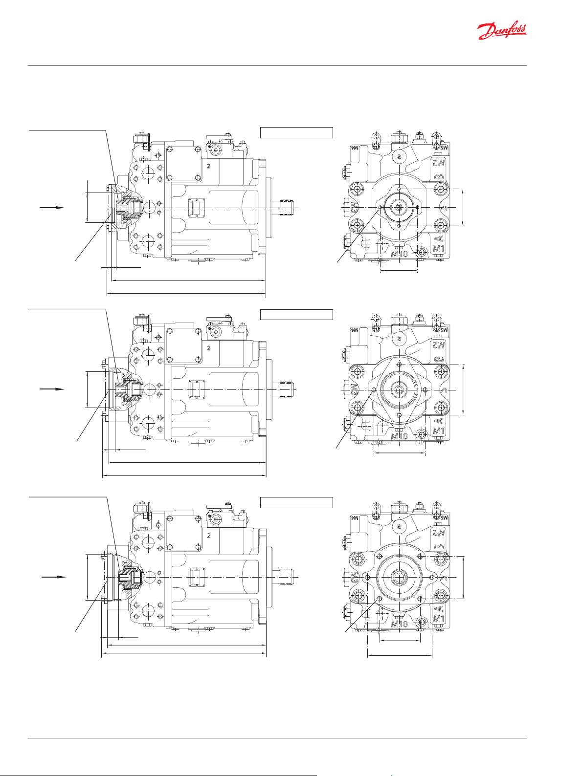
477.1
[18.78]
460.4
[18.13]
For O-ring
Ø 120.32 x 2.62
[Ø 4.737 x 0.103]
"X"
Ø 127.03
[Ø 5.001]
Coupling sp line da ta:
Pitch diameter = 29.6333 [1.167]
Pressure ang le = 30°
Numbe r of tee th = 14
Pitch = 12/24
ANSI B92.1-1970, class 6,
fillet roo t side fit
Len gth of spline = 22.1 [0.87]
+ 0.13
- 0.00
[+0.005]
[- 0.000]
30.5
[1.20]
SAE B, opt ion BC
475.1
[18.70]
457.4
[18.01]
For O-ring
Ø 94.92 x 2.62
[Ø 3.737 x 0.103]
"X"
Ø 101.65
[Ø 4.002]
Coupling sp line da ta:
Pitch diameter = 20.6375 [0.8125]
Pressure ang le = 30°
Numbe r of tee th = 13
Pitch = 16/32
ANSI B92.1-1970, class 6,
fillet roo t side fit
Len gth of spline = 29.5 [1.16]
+ 0.13
- 0.00
[+0.005]
[- 0.000]
17.5 [0.69]
SAE C, op tion CD
6 thre ads
1/2-13UNC-2B
22 [0.87] de ep
View "X"
114.5
[4.51]
114.5
[4.51]
181
[7.13]
463.90
[18.26]
450.30
[17.73]
Coupling sp line da ta:
Pitch diameter = 14.288 [0.5625]
Pressure ang le = 30°
Numbe r of tee th =
9
Pitch = 16/32
ANSI B92.1-1970, class 6,
fillet roo t side fit
Len gth of spline = 17.8 [0.70]
For O-ring
Ø 82.22 x 2.62
[Ø 3.237 x 0.103]
+ 0.13
- 0.00
[+ 0.005]
[- 0.000]
Ø 82.6
[Ø 3.252]
15
[0.59]
"X"
SAE A, option AB
View "X"
4 thre ads
3/8-16UNC-2B
17.8 [0.70] dee p
106.375
[4.188]
106.375
[4.188]
4 thre ads
1/2-13UNC-2B
22 [0.87] de ep
View "X"
146
[5.75]
146
[5.75]
P102 062
Technical Information
Series 90 Axial Piston Pumps
Installation Drawings
Auxiliary mounting pad - options AB, BC, CD, DE, EF, EG, BB
76 | © Danfoss | March 2022 BC152886483413en-000910
Page 77

View "X"
SAE E, option EF
View "X"
SAE E, option EG
2
SAE D, option DE
"X"
485.8
[19.13]
469.1
[18.47]
For O-ring
Ø 153 x 3.0
[Ø 6.02 x 0.118]
Coupling spline data:
Pitch diameter = 41.275 [1.625]
Pressure angle = 30°
Number of teeth = 13
Pitch = 8/16
ANSI B92.1-1970, class 6,
fillet root side fit
Length of spline = 25.9 [1.02]
+ 0.13
- 0.00
[+0.005]
[- 0.000]
Ø 152.45
[Ø 6.002]
49.9
[1.96]
2
494.1
[19.45]
469.1
[18.47]
For O-ring
Ø 158.42 x 2.62
[Ø 6.24 x 0.10]
"X"
Coupling spline data:
Pitch diameter = 41.275 [1.625]
Pressure angle = 30
Number of teeth = 13
Pitch = 8/16
ANSI B92.1-1970, class 6,
fillet root side fit
Length of spline = 25.9 [1.02]
48.5
[1.91]
Ø 165.15
[Ø 6.501]
+ 0.13
- 0.00
[+0.005]
[- 0.000]
2
469.1
[18.47]
For O-ring
Ø 164.77 x 2.62
[Ø 6.48 x 0.10]
"X"
Coupling spline data:
Pitch diameter = 42.862 [1.687]
Pressure angle = 30°
Number of teeth = 27
Pitch = 16/32
ANSI B92.1-1970, class 6,
fillet root side fit
Length of spline = 28.5 [1.12]
46.5
[1.83]
Ø 165.15
[Ø 6.501]
+ 0.13
- 0.00
[+0.005]
[- 0.000]
494.1
[19.45]
B
M2
S
a
M1
M3
A
M10
M5
M4
4 threads
3/4-10UNC-2B
41 [1.61] deep
161.6
[6.36]
161.6
[6.36]
B
M2
S
a
M1
M3
A
M10
M5
M4
4 threads
3/4-10UNC-2B
41 [1.61] deep
224.5
[8.84]
224.5
[8.84]
B
M2
S
a
M1
M3
A
M10
M5
M4
4 threads
3/4-10UNC-2B
41 [1.61] deep
224.5
[8.84]
224.5
[8.84]
P102 063
Technical Information
Series 90 Axial Piston Pumps
Installation Drawings
Auxiliary mounting pad – options AB, BC, CD, DE EF, EG, BB
©
Danfoss | March 2022 BC152886483413en-000910 | 77
Page 78

2
475.1
[18.70]
457.4
[18.01]
For O-ring
Ø 94.92 x 2.62
[Ø 3.737 x 0.103]
"X"
Ø 101.65
[Ø 4.00]
Coupling spline data:
Pitch diameter = 23.8125 [0.9375]
Pressure angle = 30
Number of teeth = 15
Pitch = 16/32
ANSI B92.1-1970, class 6,
fillet root side fit
Length of spline = 24.49 [0.96]
+ 0.13
- 0.00
[+0.005]
[- 0.000]
22.6
[0.89]
B
M2
S
a
M1
M3
A
M10
M5
M4
4 threads
1/2-13UNC-2B
22 [0.87] deep
View "X"
146
[5.75]
146
[5.75]
SAE B-B, option BB
P102 064
7.9
[0.311]
66.8
[2.63]
Coupling must not protude beyond this surface
Option F1
ANSI B92.1 1970 KL.5 (13 tooth)
38.54
[1.52]
27.9
[1.10]
43.89
[1.73]
7.9
[0.311]
Coupling must not protude beyond this surface
Option C8
ANSI B92.1 1970 KL.5 (27 tooth)
39
[1.54]
56
[2.20]
44.35
[1.75]
42.8625
[1.687]
P108 508E
66.8
[2.63]
41.275
[1.625]
*
* Minimum active spline length
for the specified torque ratings
*
Shaft spline data:
Pitch diameter = 41.275 [1.625]
Pressure angle = 30°
Number of teeth = 13
Pitch = 8/16
ANSI B92.1
Fillet root side fit
Shaft spline data:
Pitch diameter = 42.8625 [1.6875]
Pressure angle = 30°
Number of teeth = 27
Pitch = 16/32
ANSI B92.1
Fillet root side fit
Option CA
View "W"
C3
"W"
C1 C1
C2
Port
M4
C4 maximumC4 maximum
Port
M5
Displacement limiter
option 4
limitation both sides
P102065
2
Technical Information
Series 90 Axial Piston Pumps
Installation Drawings
Auxiliary mounting pad – options AB, BC, CD, DE, EF, EG, BB
Shaft dimensions
Cover Plate
78 | © Danfoss | March 2022 BC152886483413en-000910
Page 79

View "W"
C5 maximum
Option DC & DD
"W"
P102065a
a
b
2
C5.1
C5.2
Technical Information
Series 90 Axial Piston Pumps
Installation Drawings
Dimensions
Frame size C1 C2 C3 C4 maximum (option 4)
055 69.2 [2.72] 179.4 [7.06] 103.6 [4.08] 114 [4.48]
075 74.2 [2.92] 185.7 [7.31] 109.4 [4.31] 118 [4.65]
100 83.3 [3.28] 183.3 [7.22] 118.3 [4.66] 136 [5.35]
130 86.6 [3.41] 209.3 [8.24] 137.2 [5.40] 141 [5.55]
180 - - - 184 [7.24]
250 - - - 184 [7.24]
3-Position (F-N-R) Electric Control
Dimensions
Frame size C5 maximum C5.1 C5.2
055 200.6 [7.90] 108.8 [4.28] 106.2 [4.18]
075 207.9 [8.19] 108.8 [4.28] 106.2 [4.18]
100 216.8 [8.54] 117.4 [4.62] 97.6 [3.84]
130 235.7 [9.28] 102.4 [4.03] 112.6 [4.43]
180 252.4 [9.94] 94.6 [7.32] 120.4 [4.74]
250
[option DD only]
©
Danfoss | March 2022 BC152886483413en-000910 | 79
210.4 [8.28] 94.6 [7.32] 120.4 [4.74]
Page 80

C7
(Frame size 042 only)
Frame size 042 only
C7
View "W"
2
P102 066
"W"
C6
Port
X1
Port
X2
Option KA & KP
Packard-
Connector
option KP
Option HF, HS
View "W"
C8.2 (port X1)
C9
C11
Port X1
2
C12
C10
Port X2
"W"
C8.1 (port X2)
Technical Information
Series 90 Axial Piston Pumps
Installation Drawings
Electric Displacement Control (EDC) with MS-Connector or Packard® connector
Dimensions
Frame size C6 C7
055 95.3 [3.75] 141.2 [5.56]
075 105.2 [4.14] 144.8 [5.70]
100 114.0 [4.49] 153.7 [6.05]
130 99.1 [3.90] 172.7 [6.80]
180 93.4 [3.68] 190.0 [7.48]
250 93.4 [3.68] 226.2 [8.91]
Hydraulic Displacement Control (HDC)
Dimensions
Frame size C8.1 C8.2 C9 C10 C11 C12
055 150.8 [5.94] 139.0 [5.47] 71.0 [2.79] 75.7 [2.98] 105.6 [4.15] 115.2 [4.53]
075 148.9 [5.86] 139.0 [5.47] 68.2 [2.68] 67.0 [2.63] 121.8 [4.79] 125.3 [4.93]
80 | © Danfoss | March 2022 BC152886483413en-000910
Page 81

Option MB
View "W"
C14
"W"
Neutral
start switch
C13
2
P102 067
Technical Information
Series 90 Axial Piston Pumps
Installation Drawings
Dimensions (continued)
Frame size C8.1 C8.2 C9 C10 C11 C12
100 158.0 [6.22] 149.0 [5.86] 76.8 [3.02] 67.0 [2.63] 127.9 [5.03] 131.4 [5.17]
130 176.7 [6.95] 167.7 [6.60] 61.8 [2.43] 67.0 [2.63] 142.1 [5.59] 145.6 [5.73]
180/250 194.0 [7.63] 185.0 [7.28] 54.0 [2.12] 67.0 [2.63] 148.6 [5.85] 152.1 [5.99]
Manual Displacement Control (MDC) with neutral start switch
Dimensions
Frame size C13 C14
055 18.0 [071] 100.0 [3.94]
075 25.0 [0.98] 106.9 [4.21]
100 31.3 [1.23] 115.8 [4.56]
130 46.0 [1.81] 134.5 [5.29]
180 52.0 [2.04] 151.8 [5.97]
250 52.0 [2.04] 151.8 [5.97]
©
Danfoss | March 2022 BC152886483413en-000910 | 81
Page 82

"V"
"W"
View "V"
View "W"
Y
X
Y
P003 165
Option FA, FB, FC, FD
Option FG, FH
B
A
Technical Information
Series 90 Axial Piston Pumps
Installation Drawings
Electrohydraulic Displacement Control (NFPE)(except 075 NFPE)
Dimensions
Frame Size Option “X” “Y”
055 FA, FB, FC, FD 207.00 [8.15] 145.00 [5.71]
075 Special version see Frame Size 075 NFPE Options FK, FL, FM, FN on page 57
100 FA, FB, FC, FD 235.00 [9.25] 161.10 [6.34]
100 FG, FH 176.60 [6.95]
130 FG, FH 244.10 [9.61] 195.50 [7.70]
180 FG, FH 290.00 [11.42] 213.00 [8.39]
250 — — —
82 | © Danfoss | March 2022 BC152886483413en-000910
Page 83

F4 maximum
Gauge port M3
charge pressure
after filter
9/16-18UNF
View "X"
Gauge port M6
charge pressure
before filter
9/16-18UNF
Option P & L
"X"
F1 = short filter cartridge (option P)
F2 = long filter cartridge (option L)
F3
22.86
[0.90]
20.3 minimum
[0.80 minimum]
Required
for removal
180
180
Ø 94.2 maximum
[Ø 3.71 maximum]
Frame size 042 – 130 = option P
Frame size 042 – 250 = option L
Option R & T
View "X"
Port E
from filter
7/8-14UNF (option R)
1 1 /
16
-12UN (option T)
5.6
[0.22]
5.6
[0.22]
Port D
to filter
7/8-14UNF
(option R)
1 1 /
16
-12UN
(option T)
F5 maximum
F6 maximum
F7 maximum
"X"
F3
Gauge port M3
charge pressure
after filter
9/16-18UNF
180
180
28.5
[1.12]
Frame size 042 – 130 = option R
Frame size 180 – 250 = option T
P102 068
Technical Information
Series 90 Axial Piston Pumps
Installation Drawings
Integral Pressure Filter
Remote pressure – without filter
Dimensions
Frame size F1 F2 F3 F4 maximum F5 maximum F6 maximum F7 maximum
055 174.5 [6.87] 262.6 [10.34] 240.9 [8.19] 209.6 [8.25] 114.3 [4.50] 154.3 [6.07] 169.6 [6.68]
075 174.5 [6.87] 262.6 [10.34] 253.2 [9.67] 214.4 [8.44] 119.1 [4.69] 159.1 [6.26] 174.4 [6.86]
075 NFPE 174.5 [6.87] 262.4 [10.34] 253.7 [9.99] 214 [8.441] 119 [4.691] 159 [6.264] 174 [6.866]
100 174.5 [6.87] 262.6 [10.34] 280.7 [11.05] 223.0 [8.78] 127.7 [5.03] 167.7 [6.60] 183.0 [7.20]
130 174.5 [6.87] 262.6 [10.34] 299.9 [11.81] 223.0 [9.17] 137.7 [5.03] 177.7 [6.99] 193.0 [7.60]
180 - - 327.8 [12.90] - 182.0 [7.16] 236.8 [9.32] 259.2 [10.2]
250 - - 342.8 [13.49] - 182.0 [7.16] 236.8 [9.32] 259.2 [10.2]
©
Danfoss | March 2022 BC152886483413en-000910 | 83
Page 84

Danfoss
Power Solutions GmbH & Co. OHG
Krokamp 35
D-24539 Neumünster, Germany
Phone: +49 4321 871 0
Danfoss
Power Solutions ApS
Nordborgvej 81
DK-6430 Nordborg, Denmark
Phone: +45 7488 2222
Danfoss
Power Solutions (US) Company
2800 East 13th Street
Ames, IA 50010, USA
Phone: +1 515 239 6000
Danfoss
Power Solutions Trading
(Shanghai) Co., Ltd.
Building #22, No. 1000 Jin Hai Rd
Jin Qiao, Pudong New District
Shanghai, China 201206
Phone: +86 21 2080 6201
Products we offer:
Hydro-Gear
www.hydro-gear.com
Daikin-Sauer-Danfoss
www.daikin-sauer-danfoss.com
Cartridge valves
•
DCV directional control
•
valves
Electric converters
•
Electric machines
•
Electric motors
•
Gear motors
•
Gear pumps
•
Hydraulic integrated
•
circuits (HICs)
Hydrostatic motors
•
Hydrostatic pumps
•
Orbital motors
•
PLUS+1® controllers
•
PLUS+1® displays
•
PLUS+1® joysticks and
•
pedals
PLUS+1® operator
•
interfaces
PLUS+1® sensors
•
PLUS+1® software
•
PLUS+1® software services,
•
support and training
Position controls and
•
sensors
PVG proportional valves
•
Steering components and
•
systems
Telematics
•
Danfoss Power Solutions is a global manufacturer and supplier of high-quality hydraulic and
electric components. We specialize in providing state-of-the-art technology and solutions
that excel in the harsh operating conditions of the mobile off-highway market as well as the
marine sector. Building on our extensive applications expertise, we work closely with you to
ensure exceptional performance for a broad range of applications. We help you and other
customers around the world speed up system development, reduce costs and bring vehicles
and vessels to market faster.
Danfoss Power Solutions – your strongest partner in mobile hydraulics and mobile
electrification.
Go to www.danfoss.com for further product information.
We offer you expert worldwide support for ensuring the best possible solutions for
outstanding performance. And with an extensive network of Global Service Partners, we also
provide you with comprehensive global service for all of our components.
Local address:
Danfoss can accept no responsibility for possible errors in catalogues, brochures and other printed material. Danfoss reserves the right to alter its products without notice. This also applies to products
already on order provided that such alterations can be made without subsequent changes being necessary in specifications already agreed.
All trademarks in this material are property of the respective companies. Danfoss and the Danfoss logotype are trademarks of Danfoss A/S. All rights reserved.
©
Danfoss | March 2022 BC152886483413en-000910
 Loading...