

Page 1

Technical Information
Bent Axis Variable Displ. Motors
Series 51 and 51-1
powersolutions.danfoss.com
Page 2

Technical Information
Series 51 and 51-1 Bent Axis Variable Displ. Motors
Revision history Table of revisions
Date Changed Rev
October 2017 Modified theor. corner power ratings and updated to Engineering Tomorrow 0401
March 2015 Major update. Corrected DITA CMS structure, layout, colors and all tables. CA
Jan 2014 Converted to Danfoss layout - DITA CMS BA
Jun 2005 First version AA
2 | © Danfoss | October 2017 520L0440 | BC00000018en-US0401
Page 3

Technical Information
Series 51 and 51-1 Bent Axis Variable Displ. Motors
Contents
Series 51 general information
Sectional view of Series 51, proportional control.................................................................................................................7
Sectional view of Series 51-1, two-position control.............................................................................................................8
Pictorial diagram...............................................................................................................................................................................9
System circuit diagram...................................................................................................................................................................9
Series 51/51-1 name plates........................................................................................................................................................ 10
Technical specifications
General specifications.................................................................................................................................................................. 11
Specific data.....................................................................................................................................................................................11
Fluid specifications........................................................................................................................................................................12
Determination of nominal motor size....................................................................................................................................13
General technical specifications
Case pressure...................................................................................................................................................................................14
Speed range.....................................................................................................................................................................................14
Pressure limits................................................................................................................................................................................. 15
Loop flushing...................................................................................................................................................................................16
Minimum displacement limiter................................................................................................................................................ 17
Hydraulic fluids............................................................................................................................................................................... 17
Temperature and viscosity......................................................................................................................................................... 18
Filtration system ............................................................................................................................................................................18
Fluid selection................................................................................................................................................................................. 19
Reservoir............................................................................................................................................................................................19
Independent braking system.................................................................................................................................................... 19
Motor bearing life.......................................................................................................................................................................... 20
External shaft loads....................................................................................................................................................................... 21
External shaft load orientation..................................................................................................................................................21
Radial and thrust loads to the output shaft.................................................................................................................... 22
Allowable external shaft load, when shaft load distance is different from standard.................................22
Efficiency graphs and maps....................................................................................................................................................... 23
Speed sensor................................................................................................................................................................................... 25
Typical control and regulator applications...........................................................................................................................26
Controls circuit diagram – nomenclature – description
Option N1NN – hydraulic two-position control for 51-1 (frame size: 060, 080, 110).............................................27
Option HZB1 – hydraulic two-position control for 51 (frame size: 160, 250)........................................................... 28
Options TA** – pressure compensator control for 51-1 (frame size: 060, 080, 110)..............................................30
Option TACA: pressure compensator configuration with hydraulic Brake Pressure Defeat.........................31
Options TAD1, TAD2, TAD7: pressure compensator configuration with electric BPD.................................... 31
TAD* solenoid connectors............................................................................................................................................... 31
Option TAC2: pressure compensator configuration without Brake Pressure Defeat......................................31
Options TA** – pressure compensator controls for 51 (frame size 160, 250).......................................................... 33
Option TAC0: pressure compensator configuration with hydraulic Brake Pressure Defeat......................... 34
Option TAC2: pressure compensator configuration without Brake Pressure Defeat......................................34
Options TH** – hydraulic two-position control for 51-1 (frame size: 060, 080, 110)............................................. 35
Pressure Compensator OverRide (PCOR).........................................................................................................................35
Option THCA: pressure compensator configuration with hydraulic Brake Pressure Defeat.........................36
Options THD1, THD2, THD7: pressure compensator configuration with electric BPD....................................36
THD* solenoid connectors...............................................................................................................................................37
Option THC2: pressure compensator configuration without Brake Pressure Defeat......................................37
Options TH** – hydraulic two-position control for 51 (frame size 160, 250)............................................................38
Pressure Compensator OverRide (PCOR).........................................................................................................................38
Option THC0: pressure compensator configuration with hydraulic BPD............................................................ 39
Option THC2: pressure compensator configuration without Brake Pressure Defeat......................................39
Options E1B1, E2B1, E7B1 – electrohydraulic two-position control for 51-1 (frame size 060, 080, 110)........40
E1B1, E2B1, E7B1 solenoid connectors............................................................................................................................. 41
Options E1A5, E2A5 – electrohydraulic two-position control for 51 (frame size 160, 250).................................42
E1A5, E2A5 solenoid connectors.........................................................................................................................................43
Options F1B1, F2B1 – electrohydraulic two-position control for 51-1 (frame size 060, 080, 110)....................44
F1B1, F2B1 solenoid connectors......................................................................................................................................... 45
©
Danfoss | October 2017 520L0440 | BC00000018en-US0401 | 3
Page 4

Technical Information
Series 51 and 51-1 Bent Axis Variable Displ. Motors
Contents
Options F1A5, F2A5 – electrohydraulic two-position control for 51 (frame size 160, 250).................................46
F1A5, F2A5 solenoid connectors.........................................................................................................................................47
Options T1**, T2**, T7** – electrohydraulic two-position control for 51-1 (frame size 060, 080, 110)...........48
Option T*CA: pressure compensator configuration with hydraulic Brake Pressure Defeat..........................49
Options T*D1, T*D2, T* D7: pressure compensator configuration with electric BPD......................................49
T1D1, T2D2, T7D7 solenoid connectors......................................................................................................................50
Option T*C2: pressure compensator configuration without Brake Pressure Defeat.......................................50
Options T1**, T2** – electrohydraulic two-position control for 51 (frame size 160, 250)................................... 51
Option T*C0: pressure compensator configuration with hydraulic Brake Pressure Defeat.......................... 52
Option T*C2: pressure compensator configuration without Brake Pressure Defeat.......................................52
T1C2, T2C2 solenoid connectors................................................................................................................................... 52
Options EP**, EQ** – electrohydraulic proportional control for 51 (all frame sizes)............................................. 53
Pressure Compensator Override (PCOR)..........................................................................................................................54
Options EPA1, EQA1: pressure compensator configuration with Brake Pressure Defeat.............................. 55
Options EPA2, EQA2: pressure compensator configuration without Brake Pressure Defeat....................... 55
Options L1B1, L2B1, L7B1 – electrohydraulic proportional control for 51 (all frame sizes)................................ 56
L1B1, L2B1, L7B1 solenoid connectors..............................................................................................................................57
Options D7M1, D8M1 – electrohydraulic proportional control with PCOR and hydraulic BPD for 51
(all frame sizes)........................................................................................................................................................................58
Options D7M1, D8M1: pressure compensator configuration with hydraulic Brake Pressure Defeat........59
D7M1, D8M1 solenoid connector..................................................................................................................................59
Options HS** – hydraulic proportional control for 51 (all frame sizes)...................................................................... 60
Pressure Compensator OverRide (PCOR).........................................................................................................................60
Option HSA1: pressure compensator configuration with Brake Pressure Defeat.............................................61
Option HSA2: pressure compensator configuration without Brake Pressure Defeat......................................61
Option HZB1 – hydraulic proportional control for 51 (all frame sizes).......................................................................62
General dimensions – frame size 060
SAE flange design per ISO 3019/1............................................................................................................................................64
DIN flange design per ISO 3019/2............................................................................................................................................67
Cartridge flange..............................................................................................................................................................................70
General dimensions – frame size 080
SAE flange design per ISO 3019/1............................................................................................................................................73
DIN flange design per ISO 3019/2............................................................................................................................................76
Cartridge flange..............................................................................................................................................................................79
General dimensions – frame size 110
SAE flange design per ISO 3019/1............................................................................................................................................82
DIN flange design per ISO 3019/2............................................................................................................................................85
Cartridge flange..............................................................................................................................................................................88
General dimensions – frame size 160
SAE flange design per ISO 3019/1............................................................................................................................................91
DIN flange design per ISO 3019/2............................................................................................................................................93
Cartridge flange..............................................................................................................................................................................95
General dimensions – frame size 250
SAE flange design per ISO 3019/1............................................................................................................................................97
Dimension – Controls
Options TA** for 51-1 – Pressure Compensator Control (Frame Size: 060, 080, 110)........................................... 99
Options TA** for 51 – Pressure Compensator Control (Frame Size: 160, 250)...................................................... 100
Options TH** for 51-1 – Hydraulic Two-Position Control (Frame Size: 060, 080, 110)........................................101
Options TH** for 51 – Hydraulic Two-Position Control (Frame Size: 160, 250).....................................................102
Options E*B1, F*B1 for 51-1 – Electrohydraulic Two-Position Control (Frame Size: 060, 080, 110)...............103
Options E*A5, F*A5 for 51 – Electrohydraulic Two-Position Control (Frame Size: 160, 250)........................... 104
Options T1**, T2**, T7** for 51-1 – Electrohydraulic Two-Position Control (Frame Size: 060, 080, 110).....105
Options T1C2, T2C2 for 51 – Electrohydraulic Two-Position Control (Frame Size: 060, 080, 110)................. 106
Options EPA1, EQA1 for 51 – Electrohydraulic Two-Position Control (All Frame Sizes).................................... 107
Options L1B1, L2B1, L7B1 for 51 – Electrohydraulic Two-Position Control (All Frame Sizes).......................... 108
Options D7M1, D8M1 for 51 – Electrohydraulic Two-Position Control (Frame Size: 060, 080, 110)............. 109
4 | © Danfoss | October 2017 520L0440 | BC00000018en-US0401
Page 5

Technical Information
Series 51 and 51-1 Bent Axis Variable Displ. Motors
Contents
Options D7M1, D8M1 for 51 – Electrohydraulic Two-Position Control (Frame Size: 160, 250).......................110
Option HSA* for 51 – Hydraulic Proportional Control (All Frame Sizes)..................................................................111
Option HZB1 for 51 – Hydraulic Proportional Control (All Frame Sizes)................................................................. 112
©
Danfoss | October 2017 520L0440 | BC00000018en-US0401 | 5
Page 6

Technical Information
Series 51 and 51-1 Bent Axis Variable Displ. Motors
Series 51 general information
Series 51 and 51-1 variable displacement motors are bent axis design units, incorporating spherical
pistons.
These motors are designed primarily to be combined with other products in closed circuit systems to
transfer and control hydraulic power. Series 51 and 51-1 motors have a large maximum / minimum
displacement ratio (5:1) and high output speed capabilities. SAE, cartridge, and DIN flange configurations
are available.
A complete family of controls and regulators is available to fulfill the requirements of a wide range of
applications.
Motors normally start at maximum displacement. This provides maximum starting torque for high
acceleration.
The controls may utilize internally supplied servo pressure. They may be overridden by a pressure
compensator which functions when the motor is operating in motor and pump modes. A defeat option is
available to disable the pressure compensator override when the motor is running in pump mode.
The pressure compensator option features a low pressure rise (short ramp) to ensure optimal power
utilization throughout the entire displacement range of the motor. The pressure compensator is also
available as a stand-alone regulator.
The series 51 and 51-1 motors – Advanced technology
•
The most technically advanced hydraulic units in the industry
•
SAE, cartridge, and DIN flange motors
•
Cartridge motors designed for direct installation in compact planetary drives
•
Large displacement ratio (5:1)
•
Complete family of control systems
•
Proven reliability and performance
•
Optimum product configurations
•
Compact, lightweight
•
6 | © Danfoss | October 2017 520L0440 | BC00000018en-US0401
Page 7
3
7
1
5
121094 8
P001196
11
2
6
Technical Information
Series 51 and 51-1 Bent Axis Variable Displ. Motors
Series 51 general information
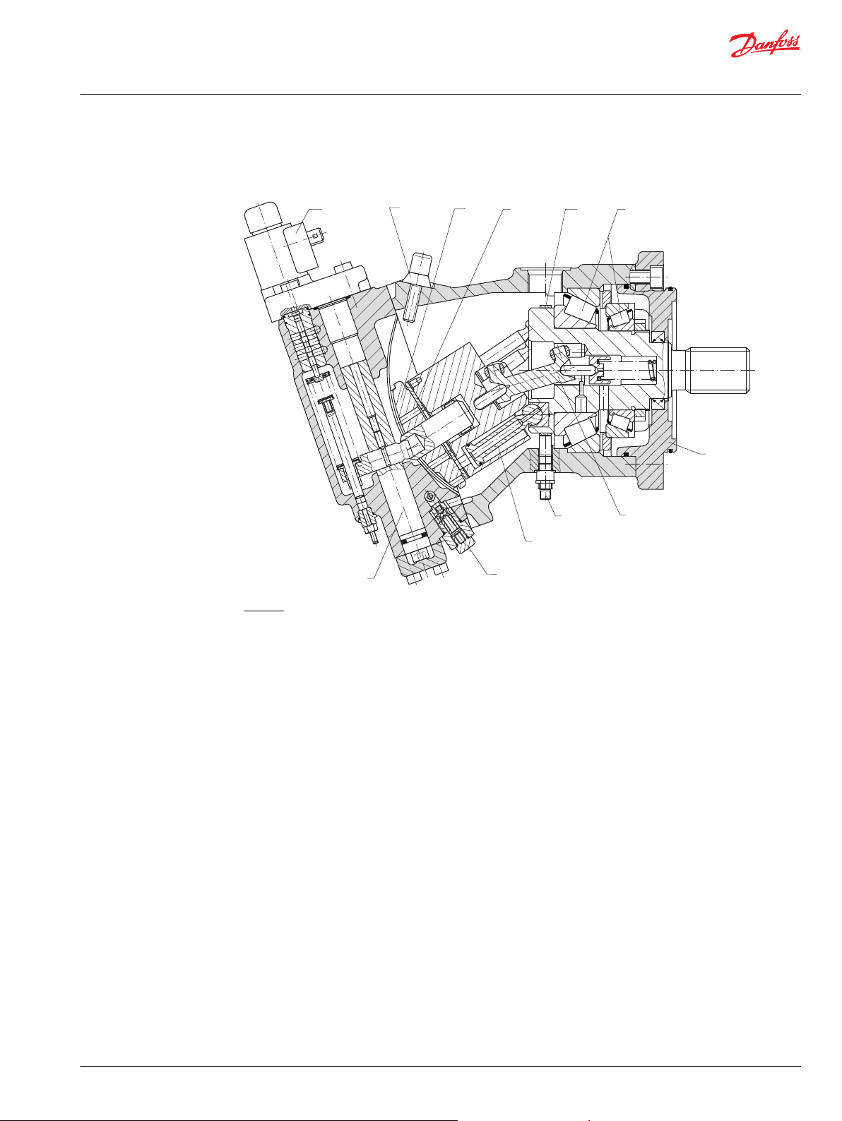
Sectional view of Series 51, proportional control
Series 51 with electric proportional control
Legend:
1 – Piston
2 – Flange
3 – Servo piston
4 – Electric proportional control
5 – Synchronizing shaft
6 – Speed sensor
7 – Charge pressure relief valve
8 – Minimum displacement limiter
9 – Valve segment
10 – Bearing plate
11 – Speed pickup ring
12 – Tapered roller bearings
©
Danfoss | October 2017 520L0440 | BC00000018en-US0401 | 7
Page 8
P001831
3
7
1
5
12109
4
8
11
2
6
Technical Information
Series 51 and 51-1 Bent Axis Variable Displ. Motors
Series 51 general information
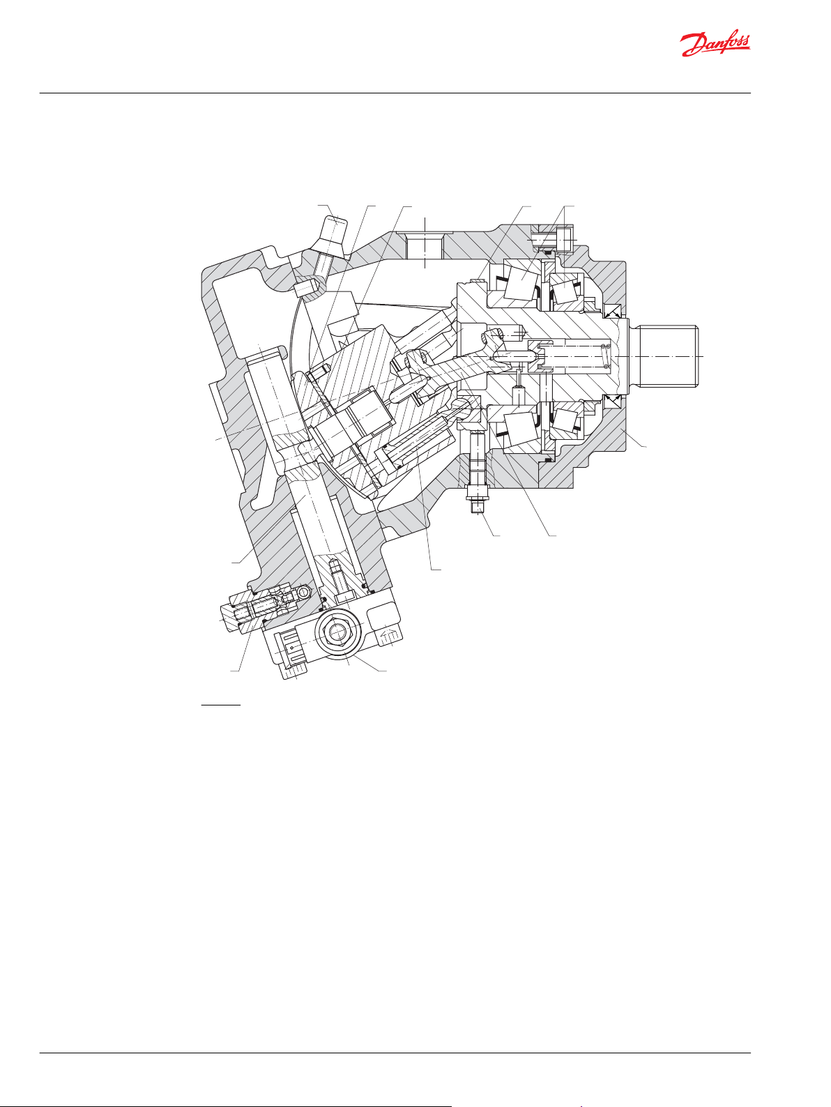
Sectional view of Series 51-1, two-position control
Series 51 with electrohydraulic two-position control
Legend:
1 – Piston
2 – Flange
3 – Servo piston
4 – Electrohydraulic two-position control
5 – Synchronizing shaft
6 – Speed sensor
7 – Charge pressure relief valve
8 – Minimum displacement limiter
9 – Valve segment
10 – Bearing plate
11 – Speed pickup ring
12 – Tapered roller bearings
8 | © Danfoss | October 2017 520L0440 | BC00000018en-US0401
Page 9

Multi-function
valve
Synchronizing shaft
Pump swashplate
Servo control
cylinder
Servo control
cylinder
Reversible variable
displacement pump
Input shaft
Heat exchanger
Loop
flushing
valve
Charge pump
Orificed check
valve
Multi-function
valve
Charge pressure
relief valve
Servo
pressure
relief
valves
to pump
case
P001 175E
Control handle
Displacement
control valve
Heat exchanger
Bypass valve
Reservoir
Vacuum gauge
Hydraulic two-position
control
Bent axis variable
displacement motor
Output shaft
Case drain fluid
Working loop
(High pressure)
Working loop
(Low pressure)
Loop flushing relief valve
Servo pressure
Suction
to motor
case
max.
disp.
T1
T7 T8
T2
T3
M
M7
Signal pressure supply
X1
L1
BB
L2
M2
M1
M4
M5
M3
L2
M4
M3
N
M1
M5
M2
A A
S
n
P001833E
Technical Information
Series 51 and 51-1 Bent Axis Variable Displ. Motors
Series 51 general information
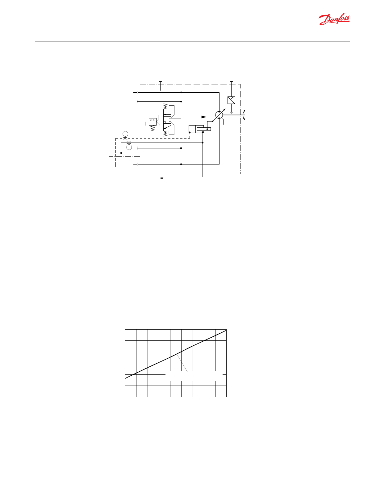
Pictorial diagram
System circuit diagram
©
Danfoss | October 2017 520L0440 | BC00000018en-US0401 | 9
Above schematic shows the function of a hydrostatic transmission using a Series 90 Axial Piston Variable
Displacement Pump with manual displacement control (MA) and a Series 51 Bent Axis Variable
Displacement Motor with hydraulic two-position control (HZ).
Page 10

Made in Germany
Serial No.
Model Code
Model No./Ident. No.
Neumünster/Germany
Place of manufacture
Ident
number
Serial
number
Model
code
Barcode
serial number
P001 832E
5084092
51V080 RS1N
L1B1 WB31 ADA
051AAF0 D400
N982211215
508 4092
Made in Germany
Serial No.
Model Code
Model No./Ident. No.
Neumünster/Germany
Place of manufacture
Ident
number
Serial
number
Model
code
Barcode
serial number
P001 832E
511685
51D110-1-RD4N
E1B1 NNU2 ADD
030AAA3 0000
N973212355
511 685
Technical Information
Series 51 and 51-1 Bent Axis Variable Displ. Motors
Series 51 general information
Series 51/51-1 name plates
Series 51 name plate
Series 51-1 name plate
10 | © Danfoss | October 2017 520L0440 | BC00000018en-US0401
Page 11

Technical Information
Series 51 and 51-1 Bent Axis Variable Displ. Motors
Technical specifications
General specifications
Most specifications for bent axis variable displacement motors are listed on these pages. For definitions
of the various specifications, see the related pages in this publication. Not all hardware options are
available for all configurations; consult the series 51 and 51-1 model code supplement or price book for
more information.
General specifications
Design
Direction of rotation
Recommended installation
Other system requirements
Specific data
Physical properties
Features Unit
Maximum
Displacement
Minimum
Theor. flow at
max. displ.
Theor. corner power at rated
speed and max. working pressure
(Δp = 450 bar [6527 psi])
Theoretical
torque
Mass moment of inertia of
rotating components
Rated speed
Maximum
*
speed
*
Contact Danfoss representative for max. speed at displacements between max. and min. displacement.
at rated speed
at max. speed
at max. displ.
at min. displ.
at max. displ.
at min. displ.
at max. displ.
at min. displ.
Axial piston motor with variable displacement, bent axis design
Clockwise and counter-clockwise (bi-directional)
Discretionary, the housing must always be filled with hydraulic fluid
Independet braking system, circuit overpressure protection, suitable reservoir
Size
060 080 110 160 250
cm3 [in3]
l/min
[US gal/min]
kW
[hp]
N•m/bar
[lbf•in/1000 psi]
2
kg•m
[slug•ft2]
min-1(rpm)
60.0 [3.66] 80.7 [4.92] 109.9
[6.71]
12 [0.73] 16.1 [0.98] 22 [1.34] 32.2 [1.96] 50.0 [3.05]
216 [57] 250 [66] 308 [81] 402 [106] 550 [145]
264 [71] 323 [85] 396 [105] 515 [136] 675 [178]
252
[338]
0.95
[583]
0.19
[117]
0.0046
[0.1092]
3600 3100 2800 2500 2200
5600 5000 4500 4000 3400
4400 4000 3600 3200 2700
7000 6250 5600 5000 4250
300
[402]
1.28
[784]
0.26
[156]
0.0071
[0.1685]
371
[498]
1.75
[1067]
0.35
[214]
0.0128
[0.3037]
160.9
[9.82]
480
[644]
2.56
[1563]
0.51
[313]
0.0234
[0.5553]
250 [15.26]
638
[856]
3.98
[2428]
0.80
[486]
0.0480
[1.1580]
©
Danfoss | October 2017 520L0440 | BC00000018en-US0401 | 11
Page 12

Technical Information
Series 51 and 51-1 Bent Axis Variable Displ. Motors
Technical specifications
System and case pressure
Parameter
Maximum delta
Fluid specifications
System pressure
Case pressure
Fluid specifications
Features Unit
Viscosity
Temperature range
Cleanliness and Filtration
1)
At the hottest point, normally case drain port.
2)
Minimum: cold start, short term t<3 min, p<50 bar, n<1000 rpm.
Maximum
Minimum low
Rated
Maximum (cold start)
Minimum (at rated speed)
Minimum intermittent
Recommended range
Maximum intermittent
Minimum
1)2)
Rated
Maximum intermittent
Required cleanliness per ISO 4406
Efficiency (charge pressure filtration)
Efficiency (suction / return line filtration)
Recommended inlet screen mesh size
Unit
bar [psi]
mm2/s
[SUS]
°C
[°F]
-
β-ratio
µm 100 – 125
All sizes
480 [7000]
510 [7400]
10 [145]
3 [44]
5 [73]
0.3 [4.35]
All sizes
7 [49]
12-80 [66-366]
1600 [7416]
-40 [-40]
104 [220]
115 [240]
22/18/13
β
= 75 (β10 ≥ 10)
15-20
β
= 75 (β10 ≥ 2)
35-45
12 | © Danfoss | October 2017 520L0440 | BC00000018en-US0401
Page 13

Vg • n
1000 •
v
Qe =
Vg • p •
mh
20 •
Me =
Qe • p •
t
600
=
Me • n
9550
Pe=
n =
Qe • 1000 •
v
V
g
Vg • n
231 •
v
Qe =
Vg • p •
mh
2 •
Me =
Vg • n • p •
t
396 000
Pe=
n =
Qe • 231 •
v
V
g
Technical Information
Series 51 and 51-1 Bent Axis Variable Displ. Motors
Technical specifications
Determination of nominal motor size
Based on SI units Based on US units
Where:
Q
Input flow (l/min)
e
M
Output torque (N•m)
e
P
Output power (kW)
e
n Speed (min-1)
V
Motor displacement per rev. (cm3/rev)
g
p
High pressure (bar)
high
p
Low pressure (bar)
low
∆p High pressure minus Low pressure (bar)
η
Motor volumetric efficiency
v
η
Mechanical-hydraulic efficiency
mh
η
Motor total efficiency (ηv • ηmh)
t
Where:
Q
Input flow [US gal/min]
e
M
Output torque [lb•in]
e
P
Output power [hp]
e
n Speed [rpm]
V
Motor displacement per rev. [in3/rev]
g
p
High pressure [psi]
high
p
Low pressure [psi]
low
∆p High pressure minus Low pressure [psi]
η
Motor volumetric efficiency
v
η
Mechanical-hydraulic efficiency
mh
η
Motor total efficiency (ηv • ηmh)
t
©
Danfoss | October 2017 520L0440 | BC00000018en-US0401 | 13
Page 14
W
Technical Information
Series 51 and 51-1 Bent Axis Variable Displ. Motors
General technical specifications
Case pressure
Under normal operating conditions, case pressure must not exceed the rated pressure. Momentary case
pressure exceeding this rating is acceptable under cold start conditions, but still must stay below the
maximum pressure rating.
The minimum pressure provides proper lubrication at high speeds.
Operation with case pressure in excess of these limits may result in external leakage due to damage to
seals, gaskets, and/or housings.
Case pressure
Parameter
Rated
Case pressure
Speed range
Rated speed is the speed limit recommended at full power condition and is the highest value at which
normal life can be expected.
Maximum speed is the highest operating speed permitted and cannot be exceeded without reduction
in the life of the product or risking immediate failure and loss of driveline power (which may create a
safety hazard). In the range between rated and maximum speed please contact your Danfoss Power
Solutions representative.
Maximum (cold start)
Minimum (at rated speed)
Unit
bar [psi]
All sizes
3 [44]
5 [73]
0.3 [4.35]
Warning
The loss of hydrostatic drive line power in any mode of operation (e.g., forward, reverse, or “neutral”) may
cause the loss of hydrostatic braking capacity. A braking system, redundant to the hydrostatic
transmission must, therefore, be provided which is adequate to stop and hold the system should the
condition develop.
Speed limits
Features Unit
at max. displ.
Rated speed
at min. displ.
min-1(rpm)
at max. displ.
Maximum speed
at min. displ.
060 080 110 160 250
3600 3100 2800 2500 2200
5600 5000 4500 4000 3400
4400 4000 3600 3200 2700
7000 6250 5600 5000 4250
Size
14 | © Danfoss | October 2017 520L0440 | BC00000018en-US0401
Page 15

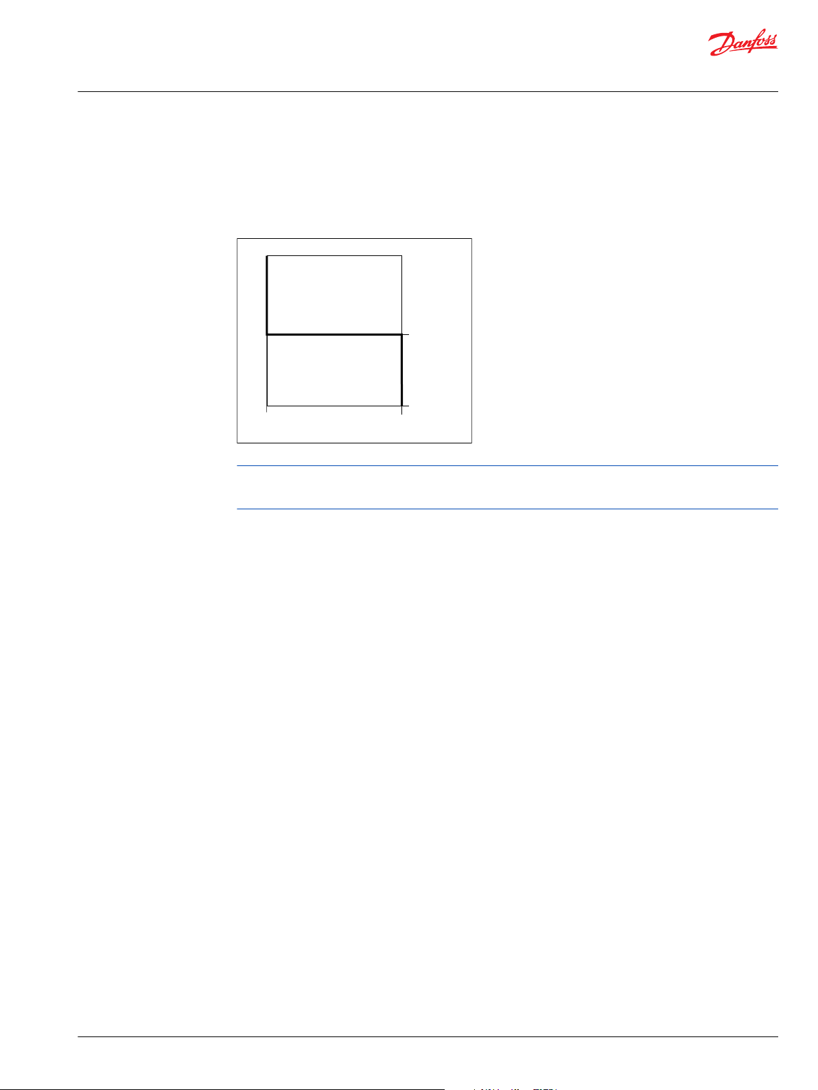
Rated speed
at min. displacement
Rated speed
at max. displacement
Acceptable operating range
Maximim speed
at min. displacement
Maximum speed
at max. displacement
Curve determined by rated flow
Min. displacement Max. displacement
P001 781E
Speed min
-1
(rpm)
Motor angle (degrees)
Technical Information
Series 51 and 51-1 Bent Axis Variable Displ. Motors
General technical specifications
Speed limits
For operation within the range above the acceptable range contact Danfoss Power Solutions
representative.
Pressure limits
System pressure is the dominant operating variable affecting hydraulic unit life. High pressure, which
results from high load, reduces expected life in a manner similar to the affects of high load on other
mechanical assemblies such as engines and gear boxes. There are load-to-life relationships for the
rotating group and for the shaft anti-friction bearings.
Continuous pressure is the pressure at which the hydrostatic system could operate continuously and still
achieve acceptable hydrostatic life. This pressure level varies depending on operating speed, and on the
life requirements for a particular application. While most mobile applications require system pressure to
vary widely during operation, a “weighted average” pressure can be derived from a machine duty cycle.
(A duty cycle is a means of quantifying the pressure and speed demands of a particular system on a
percent time basis). Once a duty cycle has been determined or estimated for a specific application,
contact your Danfoss representative for system life ratings for the application.
Maximum delta pressure is the highest intermittent pressure allowed, and is the relief valve setting. It is
determined by the maximum machine load demand. For most systems, the load should move at this
pressure.
Maximum pressure is assumed to occur a small percentage of operating time, usually less than 2 % of
the total. Both the continuous and maximum pressure limits must be satisfied to achieve the expected
life.
Minimum low pressure must maintained under all operating conditions to avoid cavitation.
System pressure range, input
Maximum delta pressure Minimum low pressure Maximum pressure
480 [7000 psi] 10 [145 psi] 510 [7400 psi]
©
Danfoss | October 2017 520L0440 | BC00000018en-US0401 | 15
Page 16
W
Loop flushing relief valve
Loop flushing shuttle spool
P001 782E
A B
P001 830
Technical Information
Series 51 and 51-1 Bent Axis Variable Displ. Motors
General technical specifications
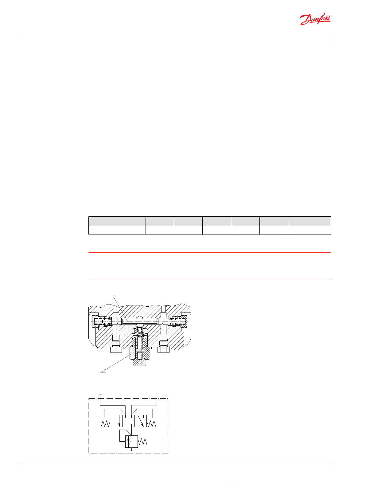
Loop flushing
An integral non-adjustable loop flushing valve is incorporated into all these motors. Installations that
require fluid to be removed from the low pressure side of the system circuit because of cooling
requirements or contamination removal will benefit from loop flushing.
The integral loop flushing valve is equipped with an orificed charge pressure relief valve designed with a
cracking pressure of 16 bar [232 psi].
Valves are available with several orifice sizes to meet the flushing flow requirements of all system
operating conditions.
The total system charge pump flow should be of sufficient volume to accommodate:
The number of motors in the system
•
System efficiency under worst case conditions
•
Pump control requirements
•
External needs
•
Although charge pump sizing requires the consideration of many system variables, the following table
gives a recommendation of what charge pump displacement may be required to accommodate the
flushing flow of each available charge relief valve orifice.
Recommended charge pump displacement
Loop flushing valve E4, E6 F0 F3 G0 G3 H0
Charge pump size (cm3) 8 11 14 17 or 20 26 34, 47 or 65
Warning
The loss of hydrostatic drive line power in any mode of operation (e.g., forward, reverse, or “neutral”
mode) may cause the loss of hydrostatic braking capacity. A braking system, redundant to the hydrostatic
transmission must, therefore, be provided which is adequate to stop and hold the system should the
condition develop.
Loop flushing valve
Hydraulic schematic
16 | © Danfoss | October 2017 520L0440 | BC00000018en-US0401
Page 17
0 5
[1.3]10[2.6]15[4.0]20[5.3]
Case flow l/min [US gal/min]
Low system pressure minus case pressure
bar [psi]
25
[6.6]30[8.0]35[9.2]40[10.6]
[508]
35
[363]
25
[218]
15
[73]
5
P001 860E
E4 E6 F0 F3 G0 G3 H0
C
Technical Information
Series 51 and 51-1 Bent Axis Variable Displ. Motors
General technical specifications
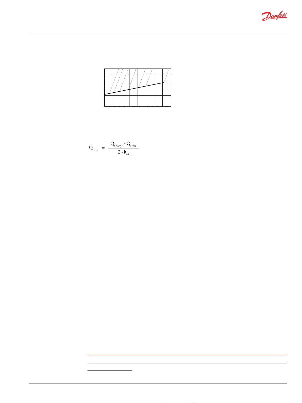
Case flow characteristic
Equation:
Where:
Q
– flushing flow per motor
Flush
Q
– charge flow at operating speed
Charge
kMo – number of motors feeded by one pump
Q
– sum of external leakages
Leak
Minimum displacement limiter
Hydraulic fluids
©
Danfoss | October 2017 520L0440 | BC00000018en-US0401 | 17
Q
includes:
Leak
motor leakage
•
pump leakage + internal consumers:
•
8 l/min [2.11 US gal/min] for displacement control pumps or
‒
for non-feedback controlled pumps at 200 bar [2900 psi]
‒
external consumers:
•
e.g. brakes, cylinders, and other pumps
‒
All Series 51 and 51-1 motors incorporate mechanical displacement limiters.
The minimum displacement of the motor is preset at the factory with a set screw in the motor housing. A
tamper-proof cap is provided.
Ratings and data are based on operating with hydraulic fluids containing oxidation, rust and foam
inhibitors. These fluids must possess good thermal and hydrolytic stability to prevent wear, erosion and
corrosion of the internal components.
Fire resistant fluids are also suitable at modified operating conditions. Please see Danfoss literature
Technical Information Hydraulic Fluids and Lubricants for more information.
For more information contact your Danfoss representative.
Caution
It is not permissible to mix hydraulic fluids.
Suitable hydraulic fluids:
Page 18
Technical Information
Series 51 and 51-1 Bent Axis Variable Displ. Motors
General technical specifications
Hydraulic fluids per DIN 51 524, part 2 (HLP)
•
Hydraulic fluids per DIN 51 524, part 3 (HVLP)
•
API CD, CE and CF engine fluids per SAE J183
•
M2C33F or G automatic transmission fluids (ATF)
•
Agricultural multi purpose oil (STOU)
•
Premium turbine oils (for Premium turbine oils contact your Danfoss representative).
•
Temperature and viscosity
Temperature and viscosity requirements must be concurrently satisfied. The data shown in the tables
assume petroleum-based fluids, are used.
The high temperature limits apply at the hottest point in the transmission, which is normally the motor
case drain. The system should generally be run at or below the rated temperature. The maximum
temperature is based on material properties and should never be exceeded.
Cold oil will generally not affect the durability of the transmission components, but it may affect the
ability to flow oil and transmit power; therefore temperatures should remain 16 °C [30 °F] above the pour
point of the hydraulic fluid. The minimum temperature relates to the physical properties of component
materials.
For maximum unit efficiency and bearing life the fluid viscosity should remain in the recommended
operating range. The minimum viscosity should be encountered only during brief occasions of
maximum ambient temperature and severe duty cycle operation. The maximum viscosity should be
encountered only at cold start.
Heat exchangers should be sized to keep the fluid within these limits. Testing to verify that these
temperature limits are not exceeded is recommended.
Filtration system
Viscosity and temperature range
Features Unit
Minimum intermittent
Viscosity
Temperature range
1)
At the hottest point, normally case drain port.
2)
Minimum: cold start, short term t<3 min, p<50 bar, n<1000 rpm.
Recommended range
Maximum intermittent
Minimum
1)2)
Rated
Maximum intermittent
mm2/s
[SUS]
°C
[°F]
All sizes
7 [49]
12-80 [66-366]
1600 [7416]
-40 [-40]
104 [220]
115 [240]
To prevent premature wear, ensure that only clean fluid enters the hydrostatic transmission circuit. A
filter capable of controlling the fluid cleanliness to ISO 4406, class 22/18/13 (SAE J1165) or better, under
normal operating conditions, is recommended.These cleanliness levels cannot be applied for hydraulic
fluid residing in the component housing/case or any other cavity upon delivery from the factory.
The filter may be located on the pump (integral) or in another location (remote or suction). The integral
filter has a filter bypass sensor to signal the machine operator when the filter requires changing. Filtration
strategies include suction or pressure filtration. The selection of the filter strategy depends on a number
of factors including the contaminant ingression rate, the generation of contaminants in the system, the
required fluid cleanliness, and the desired maintenance interval. Filters are selected to meet the above
requirements using rating parameters of efficiency and capacity.
Filter efficiency can be measured with a Beta ratio (βX). For simple suction-filtered closed circuit
transmissions and open circuit transmissions with return line filtration, a filter with a β-ratio within the
18 | © Danfoss | October 2017 520L0440 | BC00000018en-US0401
Page 19

C
W
Technical Information
Series 51 and 51-1 Bent Axis Variable Displ. Motors
General technical specifications
Fluid selection
range of β
= 75 (β10 ≥ 2) or better has been found to be satisfactory. For some open circuit systems,
35-45
and closed circuits with cylinders being supplied from the same reservoir, a higher filter efficiency is
recommended. This also applies to systems with gears or clutches using a common reservoir. For these
systems, a charge pressure or return filtration system with a filter β-ratio in the range of β
= 75 (β10 ≥
15-20
10) or better is typically required.
Because each system is unique, only a thorough testing and evaluation program can fully validate the
filtration system. For more information, see Design Guidelines for Hydraulic Fluid Cleanliness, Technical
Information BC00000095.
Filter βx-ratio is a measure of filter efficiency defined by ISO 4572. It is defined as the ratio of the number
of particles greater than a given diameter (“x” in microns) upstream of the filter to the number of these
particles downstream of the filter.
Filtration, cleanliness level and βx-ratio (recommended minimum)
Cleanliness per ISO 4406
Efficiency βx (charge pressure filtration)
Efficiency βx (suction and return line filtration)
Recommended inlet screen mesh size
22/18/13
β
= 75 (β10 ≥ 10)
15-20
β
= 75 (β10 ≥ 2)
35-45
100 – 125 µm
Ratings and performance data are based on operating with hydraulic fluids containing oxidation, rust
and foam inhibitors. These fluids must possess good thermal and hydrolytic stability to prevent wear,
erosion, and corrosion of motor components.
Reservoir
Independent braking system
Caution
Never mix hydraulic fluids of different types.
Fire resistant fluids are also suitable at modified operating conditions. For more information, see
Hydraulic Fluids and Lubricants, Technical Information BC00000093.
The function of the reservoir is to remove air and to provide make up fluid for volume changes associated
with fluid expansion or contraction, possible cylinder flow, and minor leakage.
The reservoir should be designed to accommodate maximum volume changes during all system
operating modes and to promote deaeration of the fluid as it passes through the tank.
A minimum reservoir volume equal to 1/2 to 1 1/2 times charge pump flow/min is suggested. This allows
30 seconds fluid dwell for removing entrained air at the maximum return flow. This is usually adequate to
allow for a closed reservoir (no breather) in most applications. The reservoir outlet to the charge pump
inlet should be above the bottom of the reservoir to take advantage of gravity separation and prevent
large foreign particles from entering the charge inlet line.
The reservoir inlet (fluid return) should be positioned so that the flow to the reservoir is discharged below
the normal fluid level, and also directed into the interior of the reservoir for maximum dwell and efficient
deaeration.
Warning
The loss of hydrostatic drive line power in any mode of operation (e.g., forward, reverse, or “neutral”
mode) may cause the loss of hydrostatic braking capacity. A braking system, redundant to the hydrostatic
transmission must, therefore, be provided which is adequate to stop and hold the system should the
condition develop.
©
Danfoss | October 2017 520L0440 | BC00000018en-US0401 | 19
Page 20
L1 • 1500
n
2
L2 =
hours
Technical Information
Series 51 and 51-1 Bent Axis Variable Displ. Motors
General technical specifications
Motor bearing life
The rated motor bearing life L
bearings, when operating at a speed of n = 1500 min-1 (rpm) with a charge pressure of 20 bar [290 psi]
and without external shaft load.
h10
shown in the table below is based on a 90 % survival rate of shaft
The rated motor bearing life L
Frame Size Effective ∆ pressure
bar [psi]
140 [2030] 19 800 18 530 16 370
060
080
110
160
250
210 [3050] 6320 5960 5340
280 [4060] 2740 2600 2350
140 [2030] 14 420 13 580 12 120
210 [3050] 4610 4370 3960
280 [4060] 2000 1910 1750
140 [2030] 15 800 14 890 13 330
210 [3050] 5040 4790 4350
280 [4060] 2180 2090 1920
140 [2030] 15 670 14 770 13 200
210 [3050] 5005 4750 4300
280 [4060] 2170 2070 1900
140 [2030] 11 760 11 130 10 020
210 [3050] 3750 3580 3260
280 [4060] 1630 1560 1440
h10
(hours)
Motor angle
6° 15° 32°
Lifetimes for speeds other than 1500 min-1 (rpm) can be calculated from:
Where: Units:
L
==Rated L10 life at 1500 min-1 (rpm)
1
n
2
Operating speed
hours
min-1 (rpm)
Contact your Danfoss Power Solutions representative for bearing life values at other pressure and angle.
20 | © Danfoss | October 2017 520L0440 | BC00000018en-US0401
Page 21
Fr
35°
35°
Fr
A
X
1
A
A
SAE-Flange design per ISO 3019/1
DIN-Flange design per ISO 3019/2
Cartridge Flange design
35°
35°
Fa
Fa
Fa
X
1
Fr
X
1
X2 < X
1
X2 > X
1
X2 < X
1
X2 > X
1
X2 < X
1
X2 > X
1
P001 166E
35°
Fr
Fr
Fr
35°
OPTIMUM LOAD
ORIENTATION
OPTIMUM LOAD
ORIENTATION
OPTIMUM LOAD
ORIENTATION
Technical Information
Series 51 and 51-1 Bent Axis Variable Displ. Motors
General technical specifications
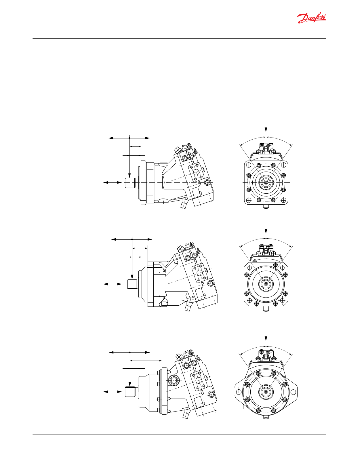
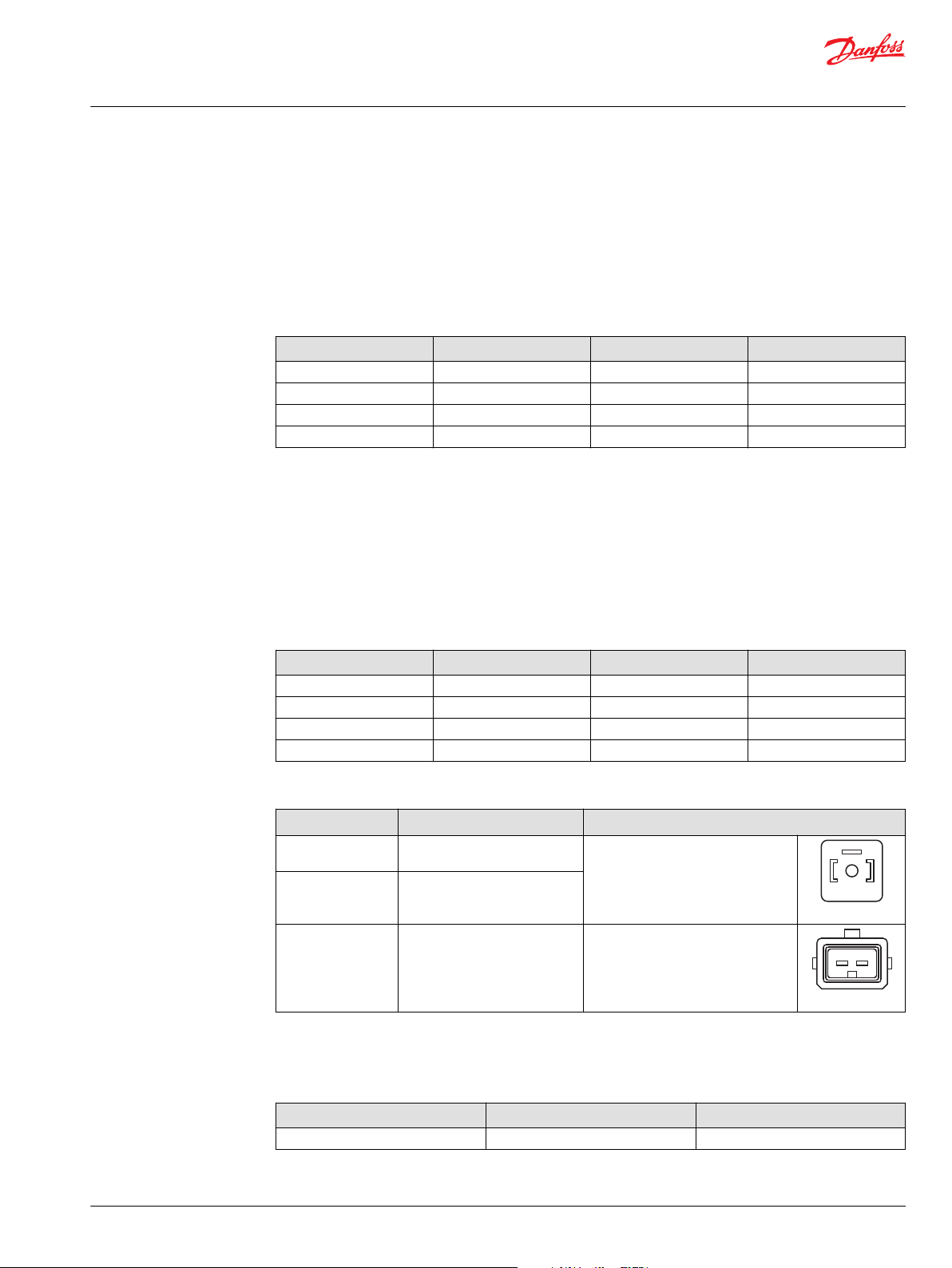
External shaft loads
Series 51 and 51-1 motors are designed with bearings that can accept external radial and thrust loads.
The external radial shaft load limits are a function of the load position, the load orientation, and operating
conditions of the unit.
External shaft load orientation
©
Danfoss | October 2017 520L0440 | BC00000018en-US0401 | 21
Page 22
Technical Information
Series 51 and 51-1 Bent Axis Variable Displ. Motors
General technical specifications
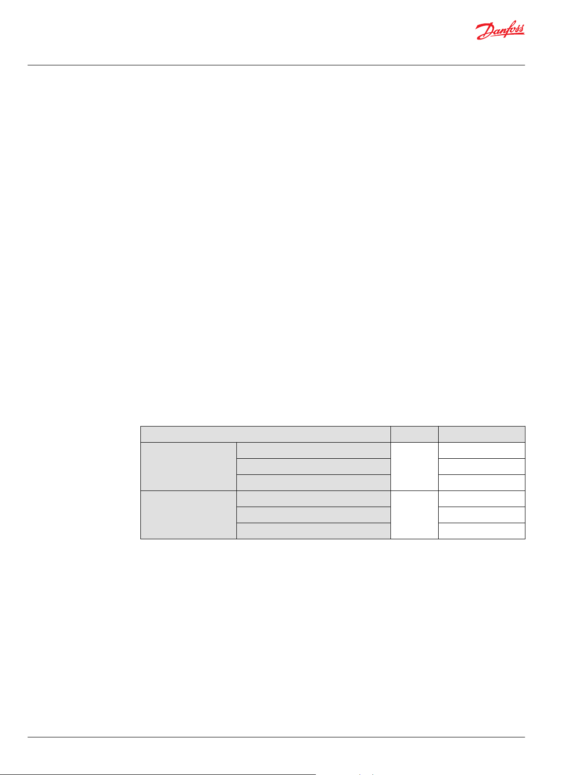
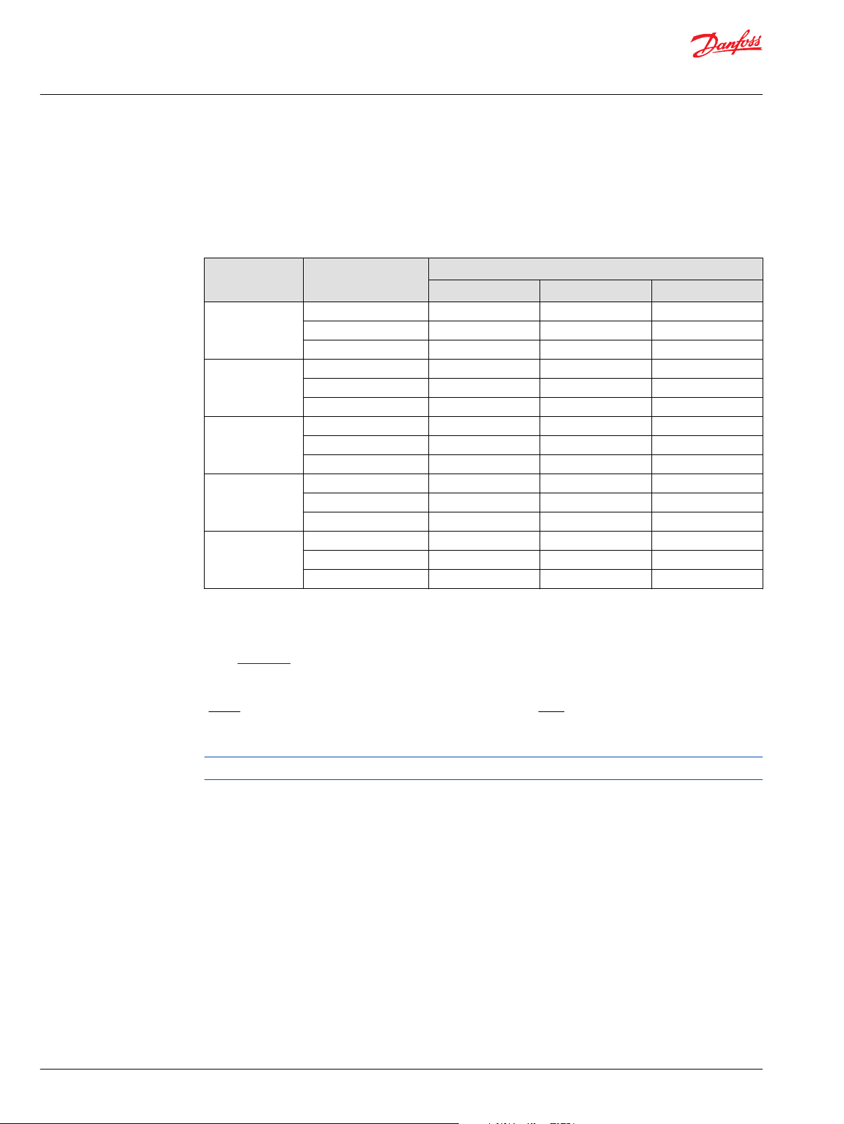
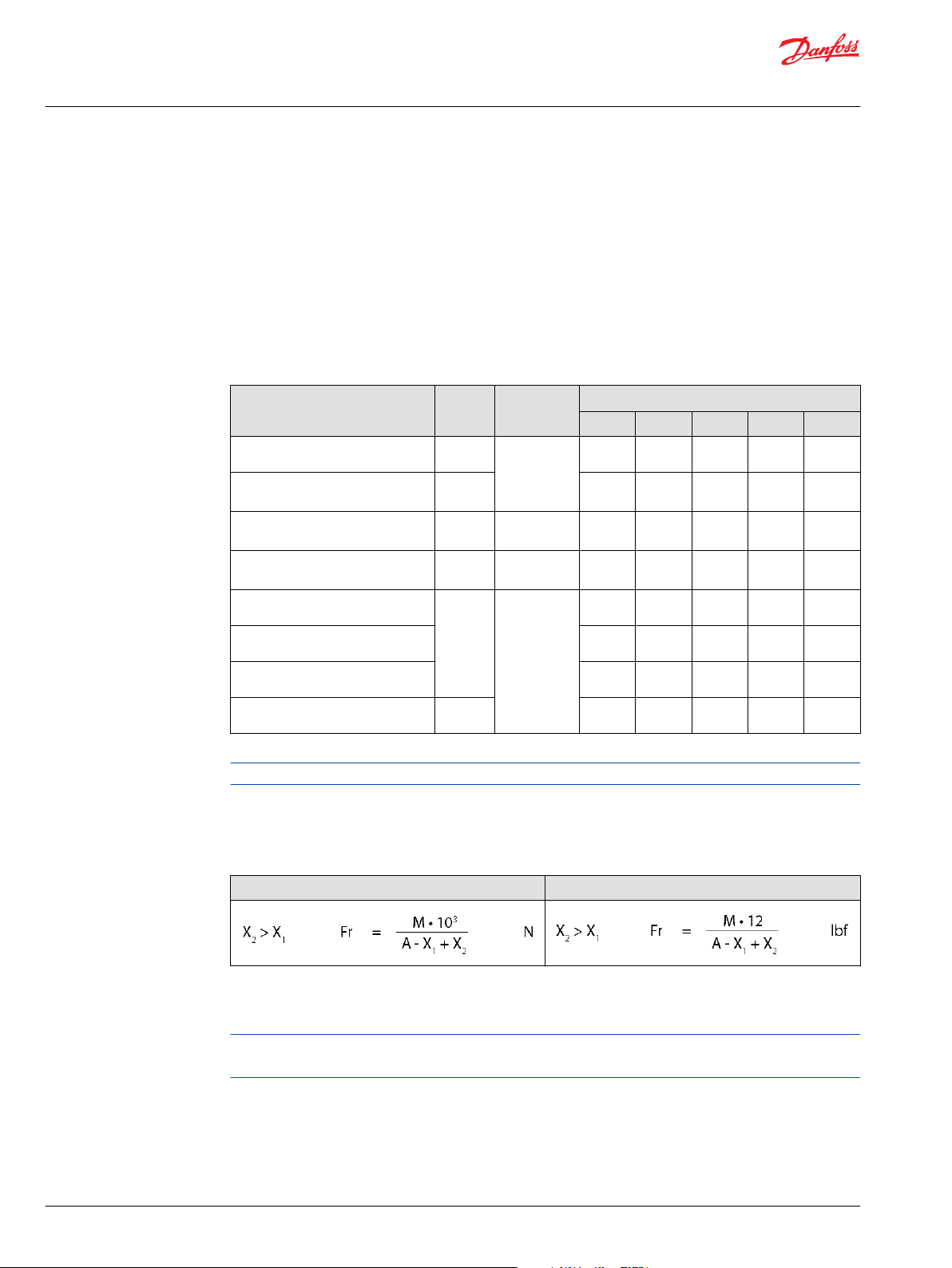
Radial and thrust loads to the output shaft
The table below provides the following information:
•
The maximum allowable radial load (Fr) based on the distance (X1) from the mounting flange to the
load.
•
The maximum allowable axial load (Fa).
•
The actual distance of Fr for a given application from the mounting flange to the load (X2).
•
The basic distance (A).
•
Fa/∆p ratio of allowable axial load, dependent upon the system pressure.
Radial and thrust loads to the output shaft
Feature Symbol Unit
Maximum allowable radial load
Max. allow. axial load at zero rpm, or
running in the idle pressure
Max. allowable bending moment
Max. allowable axial load at pressure
Distance SAE mounting flange
Distance DIN mounting flange 57.2
Distance Cartridge mount. flange 117.6
Basic distance A 25.2
– = not available
060 080 110 160 250
Fr
Fa 1100
M
Fa/∆p
X
1
N [lb]
N•m
[lb•in]
N/bar
[lb/1000 psi]
mm [in]
10 000
[2248]
[247]
252
[2230]
10.4
[161]
33.6
[1.32]
[2.25]
[4.63]
[0.99]
12 000
[2698]
1400
[315]
307
[2717]
12.6
[195]
33.6
[1.32]
57.6
[2.27]
136.1
[5.36]
25.6
[1.01]
Frame Size
14 000
[3147]
1800
[405]
766
[6780]
15.2
[236]
62.7
[2.47]
94.7
[3.73]
177.5
[7.0]
54.7
[2.15]
18 000
[4047]
2500
[562]
805
[7125]
19.2
[298]
52.7
[2.07]
84.7
[3.33]
– –
44.7
[1.76]
26 000
[5845]
4500
[1012]
970
[8585]
26.4
[409]
45.3
[1.78]
–
37.3
[1.47]
The values in the table are maximum values and are not allowed under continuous load conditions.
Allowable external shaft load, when shaft load distance is different from standard
Use this formula to calculate maximum allowable radial load when max. shaft load distance X2 is different
from X1:
Metric system: Inch system:
Metric or Inch system:
X2 > X1 Fr = Fr
max
N [lbf]
X2 is the actual distance of Fr from the mounting flange to the load for a given application. If X2< X1, Fr
could also be calculated by the first equation, but in addition the bearing life has to be checked.
Contact your Danfoss representative for load ratings of specific shafts or when the load orientation
deviates more than 35° in either direction from the optimum.
22 | © Danfoss | October 2017 520L0440 | BC00000018en-US0401
Page 23

Efficiency
%
v
o
l
u
m
e
t
r
i
c
e
f
f
i
c
i
e
n
c
y
η
v
=
2
1
0
b
a
r
[
3
0
5
0
p
s
i
]
100
95
90
85
80
0
25
50
75
100
Speed % of rated speed
P001 155E
η
t
=
4
2
0
b
a
r
[
6
0
9
0
p
s
i
]
t
o
t
a
l
e
f
f
i
c
i
e
n
c
y
η
t
=
2
1
0
b
a
r
[
3
0
5
0
p
s
i
]
η
v
=
4
2
0
b
a
r
[
6
0
9
0
p
s
i
]
Speed% of rated speed
0
System pressure bar [psi]
420
[6090]
280
[4060]
140
[2030]
0
25
50
75
100
74.5%
84.5%
90.5%
93.5%
94.5%
P001 137E
Technical Information
Series 51 and 51-1 Bent Axis Variable Displ. Motors
General technical specifications
Efficiency graphs and maps
This graph provides the volumetric and overall efficiencies for a typical Series 51 and 51-1 motor
operating at maximum displacement, system pressures of 210 and 420 bar [3050 and 6090 psi], and a
fluid viscosity of 8.2 mm²/s [53 SUS]. These efficiencies can be used for all frame sizes.
Overall and volumetric efficiency at maximum displacement
This graph shows typical overall efficiencies for Series 51 and 51-1 motors operating at maximum
displacement and system pressures up to 420 bar [6090 psi], and a fluid viscosity of 8.2 mm²/s [53 SUS].
These efficiencies can be used for all frame sizes.
Overall efficiency at maximum displacement
This graph shows typical overall efficiencies for Series 51 and 51-1 motors operating at 30% of maximum
displacement and system pressures up to 420 bar [6090 psi], and a fluid viscosity of 8.2 mm²/s (53 SUS).
These efficiencies can be used for all frame sizes.
©
Danfoss | October 2017 520L0440 | BC00000018en-US0401 | 23
Page 24

80
η
v
=
4
2
0
b
a
r
[
6
0
9
0
p
s
i
]
v
o
l
u
m
e
t
r
i
c
e
f
fi
c
i
e
n
c
y
η
v
=
2
1
0
b
a
r
[
3
0
5
0
p
s
i
]
η
t
=
4
2
0
b
a
r
[
6
0
9
0
p
s
i
]
25 50
75
1000
60
65
70
75
85
90
95
100
Efficiency %
Speed % of rated speed
o
v
e
r
a
l
l
e
f
fi
c
i
e
n
c
y
η
t
=
2
1
0
b
a
r
[
3
0
5
0
p
s
i
]
P001 156E
Speed % of rated speed
0
System pressure bar [psi]
420
[6090]
280
[4060]
140
[2030]
0
25
50
75
100
P001 138E
61%
71%
77%
80%
81%
Technical Information
Series 51 and 51-1 Bent Axis Variable Displ. Motors
General technical specifications
Overall and volumetric efficiency at 30% of maximum displacement
This graph shows typical overall efficiencies for Series 51 and 51-1 motors operating at 30% of maximum
displacement and system pressures up to 420 bar [6090 psi], and a fluid viscosity of 8.2 mm²/s (53 SUS).
These efficiencies can be used for all frame sizes.
Overall efficiency at 30% of maximum displacement
24 | © Danfoss | October 2017 520L0440 | BC00000018en-US0401
Page 25
P001 492
Turck Eurofast Connector
4 pin
(Supplied connector)
IP Rating (DIN 40 050) IP 67
Mating connector
straight right angle
No.: K14956 No.: K14957
Id.-No.: 500724 Id.-No.: 500725
P001 755E
1
2
3
4
Keyway (Ref)
Red
White
Black
Green
P002 108E
Technical Information
Series 51 and 51-1 Bent Axis Variable Displ. Motors
General technical specifications
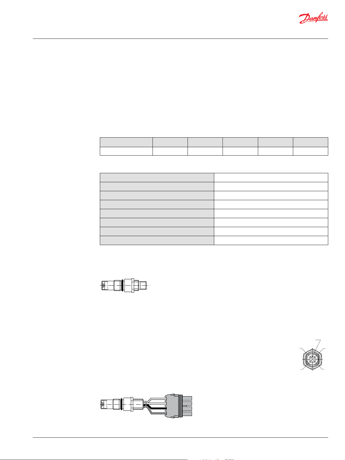
Speed sensor
An optional speed sensor for direct measurement of speed is available. This sensor may also be used to
sense the direction of rotation. A special magnetic speed pick-up ring is pressed onto the outside
diameter of the shaft and a Hall effect sensor is located in the motor housing. The sensor accepts supply
voltage and outputs a digital pulse signal in response to the speed of the ring. The output changes its
high/low state as the north and south poles of the permanently magnetized speed ring pass by the face
of the sensor. The digital signal is generated at frequencies suitable for microprocessor based controls.
The sensor is available with different connectors (see below). The SAE and DIN flange motors use a flat
end speed sensor. The cartridge flange motors use a conical end speed sensor.
Data magnetic speed pick-up ring
Frame size
Pulze/Rev 45 49 54 61 71
Speed sensor technical data
Supply voltage
Supply voltage regulated
Required current
Maximum current
Maximum frequency
Voltage "high"
Voltage "low"
Temperature range
1)
It is not acceptable to energize the 4.5-8.5 VDC speed sensor with 12 VDC battery voltage; it must be energized by a
regulated power supply. If it is desirable to energize the sensor with battery voltage, contact your Danfoss
representative for an optional speed sensor.
1)
060 080 110 160 250
4.5 – 8.5 V
15 VDC max.
12 mA at 5 VDC (no load)
20 mA at 5 VDC and 1 Hz
15 kHz
Supply voltage -0.5 VDC min.
0.5 VDC max.
-40 to 110 °C [-40 to 230 °F]
DC
©
Danfoss | October 2017 520L0440 | BC00000018en-US0401 | 25
Speed sensor with Turck Eurofast 4-pin connector
Pin 1 or A: Supply voltage
Pin 2 or B: Direction of rotation
Pin 3 or C: Speed signal, digital
Pin 4 or D: Ground common
Speed sensor with Packard Weather-Pack 4-pin connector
Page 26

A
B
C
D
Packard Weather-Pack
4 pin
(Supplied Connector)
Mating Connector
No.: K03379
Id.-No.: 505341
P001 758E
Technical Information
Series 51 and 51-1 Bent Axis Variable Displ. Motors
General technical specifications
Contact your Danfoss representative for more information.
Typical control and regulator applications
Application Control / Regulators
without PCOR with PCOR with PCOR and BPD
N1 HZ E1, E2, E7 EP, EQ F1, F2 L1, L2, L7 TA T1, T2 TH HS TA T1, T2 EP, EQ D7, D8 HS
Wheel loader
Roller compactor
Paver wheeled
Paver tracked
Sweeper
Trencher
Excavator wheeled
Fork lift truck
Agricultural
Forestry
Telehandler
Railroad
Snow groomer
Snow blower
Crane
1)
1)
1)
1)
1)
1)
1)
1)
1)
1)
1)
1)
1)
2)
3)
Suitable configuration
1)
Propel function
2)
Blow drive function
3)
Winch function
The table above is provided to assist in selecting controls and regulators for various applications. These
recommendations are based on experience with a wide range of applications.
Contact your Danfoss Power Solutions representative for more information on control selection.
26 | © Danfoss | October 2017 520L0440 | BC00000018en-US0401
Page 27
X1
(M3)
M5
B
M4
L1
N
L2
A
P001 779E
n
min.
disp.
T3
T2
System pressure bar [psi]
Servo pressure bar [psi]
0
0
200
[2900]
100
[1450]
10
[145]
20
[290]
30
[435]
300
[4350]
400
[5800]
minimum servo pressure
under all conditions
P001 877E
Technical Information
Series 51 and 51-1 Bent Axis Variable Displ. Motors
Controls circuit diagram – nomenclature – description
Option N1NN – hydraulic two-position control for 51-1 (frame size: 060, 080, 110)
A, B = Main pressure lines
L1, L2 = Drain lines
M4 = Gauge port servo pressure
M5 = Gauge port servo supply pressure
X1 (M3) = Control pressure
T1, T2, T3 = Optional orifices
N = Speed sensor
Displacement changes from maximum displacement to minimum displacement position, under load, as
control pressure at port X1 (M3) is equal to low pressure or higher.
Control pressure on port X1 (M3)
No pressure on port = maximum displacement
Control pressure on port = minimum displacement
Maximum control pressure = 50 bar [725 psi]
The graph shows the necessary external and internal (= low system pressure) control pressure X1, which
is needed to stroke the motor depending on high system pressure.
Control N1NN necessary control pressure
©
Danfoss | October 2017 520L0440 | BC00000018en-US0401 | 27
Page 28
P001 875E
min
max
Control pressure
Displacement
T8T3T7
T1
T2
max.
disp.
M2
X1
M7
B
M5
L1
M1
M4L2
A
M3 N
P100 177E
n
Technical Information
Series 51 and 51-1 Bent Axis Variable Displ. Motors
Controls circuit diagram – nomenclature – description
Control operation N1NN
Not all control options are shown in this Technical Information.
Contact your Danfoss representative for special control functions.
Option HZB1 – hydraulic two-position control for 51 (frame size: 160, 250)
A, B = Main pressure lines
L1, L2 = Drain lines
M1, M2 = Gauge port for A and B
M3, M4 = Servo pressure
M5 = Gauge port servo supply pressure internal
M7 = Gauge port control pressure
X1 = Control pressure
T1, T2, T3, T7, T8 = Optional orifices
N = Speed sensor
Displacement can be changed hydraulically under load from minimum displacement to maximum
displacement and vice versa by control pressure to port X1. For proportional control see Option HZB1 –
hydraulic proportional control for 51 (all frame sizes) on page 62
Control pressure on port X1
28 | © Danfoss | October 2017 520L0440 | BC00000018en-US0401
Page 29
P100 179E
Control pressure Δ bar [psi]
0
3
[44]
min
max
Displacement
Technical Information
Series 51 and 51-1 Bent Axis Variable Displ. Motors
Controls circuit diagram – nomenclature – description
No pressure on port = maximum displacement
Control pressure on port = minimum displacement
Maximum control pressure = 50 bar [725 psi]
The standard control start point setting = 3 bar [44 psi]
Control operation HZB1
Not all control options are shown in this Technical Information.
Contact your Danfoss representative for special control functions.
©
Danfoss | October 2017 520L0440 | BC00000018en-US0401 | 29
Page 30

M3
T3
M3
with Electric
brake pressure
defeat
with Hydraulic
brake pressure
defeat
without
Brake pressure
defeat
XB
XA
T3
M3
T3
min.
disp.
n
B
A
L1
M4
L2
N
P001 834E
min max
Displacement
Ramp < 10 bar
[145 psi]
Regulator start
Setting range
130
[1890]
370
[5370]
System pressure Δ p bar [psi]
P001 173E
Technical Information
Series 51 and 51-1 Bent Axis Variable Displ. Motors
Controls circuit diagram – nomenclature – description
Options TA** – pressure compensator control for 51-1 (frame size: 060, 080, 110)
Circuit diagram–motor with pressure compensator control TA**
Ports:
A, B = Main pressure lines
L1, L2 = Drain lines
M3, M4 = Servo pressure
XA, XB = Control pressure port brake pressure defeat (BPD)
T3 = Orifice
N = Speed sensor
Displacement is regulated automatically between minimum and maximum displacement in response to
system pressure.
Regulator start = minimum displacement
Regulator end = maximum displacement
Regulator start pressure is adjustable from 130 to 370 bar [1890 to 5370 psi].
Pressure ramp from regulator start pressure (with motor at minimum displacement) until maximum
displacement is reached is less than 10 bar [145 psi]. This ensures optimal power utilization throughout
the entire displacement range of the motor.
Control operation TA**
30 | © Danfoss | October 2017 520L0440 | BC00000018en-US0401
Page 31
A B
P001752
2 1
P001751
Technical Information
Series 51 and 51-1 Bent Axis Variable Displ. Motors
Controls circuit diagram – nomenclature – description
Option TACA: pressure compensator configuration with hydraulic Brake Pressure Defeat
A shuttle valve ahead of the pressure compensator prevents operation in the deceleration direction
(when motor is running in pump mode). This is designed to prevent rapid or uncontrolled deceleration
while the vehicle/machine is slowing down. Pressure compensator override with brake pressure defeat is
mainly used in systems with pumps having electric or hydraulic proportional controls or automotive
controls.
The shuttle valve must be controlled by a 2-line external signal, based on direction of motor rotation,
based on the following table:
Motor rotation High pressure port Control pressure on port*PCOR function
CW A XA yes
CW A XB no
CCW B XA no
CCW B XB yes
*
Differencial control pressure between port XA/XB:
∆p
= 0.5 bar [7 psi]
min
∆p
= 50 bar [725 psi]
max
Options TAD1, TAD2, TAD7: pressure compensator configuration with electric BPD
A solenoid-switched valve ahead of the pressure compensator prevents operation in the deceleration
direction (when motor is running in pump mode). This is designed to prevent rapid or uncontrolled
deceleration while the vehicle/machine is slowing down.
The solenoid valve must be controlled by an external electric signal, based on direction of motor rotation,
see the following table:
Motor rotation High pressure port Solenoid PCOR function
CW A energized yes
CW A non energized no
CCW B energized no
CCW B non energized yes
TAD* solenoid connectors
Configuration Voltage / Electric power
TAD1 12 VDC / 34 W
TAD2 24 VDC / 34 W
TAD7 12 VDC / 34 W
Solenoid plug face for DIN 46350
Mating connector No.: K09129
Id. No.: 514117
AMP Junior Timer two-pin
Mating connector No.: K19815
Id. No.: 508388
Connector (supplied)
Option TAC2: pressure compensator configuration without Brake Pressure Defeat
Pressure compensator functions when the motor is running in motor mode as well as in pump
(deceleration) mode.
Configuration option High pressure port PCOR function
TAC2 A and B yes
©
Danfoss | October 2017 520L0440 | BC00000018en-US0401 | 31
Page 32

Technical Information
Series 51 and 51-1 Bent Axis Variable Displ. Motors
Controls circuit diagram – nomenclature – description
Not all control options are shown in this Technical Information.
Contact your Danfoss representative for special control functions.
32 | © Danfoss | October 2017 520L0440 | BC00000018en-US0401
Page 33

n
max.
disp.
T7 T8
T2
T1
T3
B
M2
(X3)
M5
L1
with
Brake pressure
defeat
without
Brake pressure
defeat
M1
N
M3M4
L2
A
P001 836E
XB
XA
X4 X4
Technical Information
Series 51 and 51-1 Bent Axis Variable Displ. Motors
Controls circuit diagram – nomenclature – description
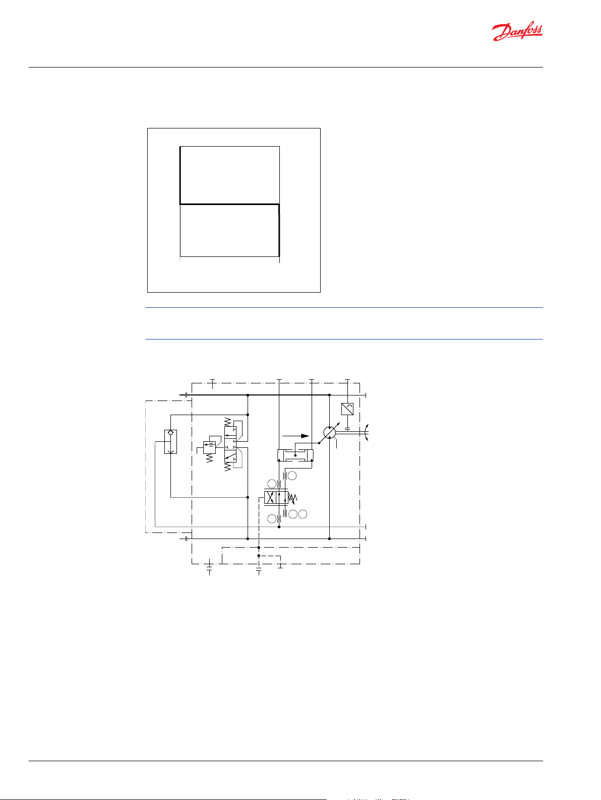
Options TA** – pressure compensator controls for 51 (frame size 160, 250)
Circuit Diagram–Motor with Pressure Compensator Control TA**
Ports:
A, B = Main pressure lines
L1, L2 = Drain lines
M1, M2 = Gauge port for A and B
M3, M4 = Gauge port servo pressure
M5 (X3) = Gauge port servo supply
XA, XB = Control pressure ports, brake pressure defeat
X4 = Gauge port pressure compensator
T1, T2, T3, T7, T8 = Optional orifices
N = Speed sensor
Displacement is regulated automatically between minimum and maximum displacement in response to
system pressure.
Regulator start = minimum displacement
Regulator end = maximum displacement
Regulator start pressure is adjustable from 130 to 370 bar [1890 to 5370 psi].
Pressure ramp from regulator start pressure (with motor at minimum displacement) until maximum
displacement is reached is less than 10 bar [145 psi]. This ensures optimal power utilization throughout
the entire displacement range of the motor.
©
Danfoss | October 2017 520L0440 | BC00000018en-US0401 | 33
Page 34

min max
Displacement
Ramp < 10 bar
[145 psi]
Regulator start
Setting range
130
[1890]
370
[5370]
System pressure Δ p bar [psi]
P001 173E
Technical Information
Series 51 and 51-1 Bent Axis Variable Displ. Motors
Controls circuit diagram – nomenclature – description
Control operation TA**
Option TAC0: pressure compensator configuration with hydraulic Brake Pressure Defeat
A shuttle valve ahead of the pressure compensator prevents operation in the deceleration direction
(when motor is running in pump mode). This is designed to prevent rapid or uncontrolled deceleration
while the vehicle/machine is slowing down.
Pressure compensator override with brake pressure defeat is mainly used in systems with pumps having
electric or hydraulic proportional controls or automotive controls.
The shuttle valve must be controlled by a 2-line external signal, based on direction of motor rotation, see
the following table.
Motor rotation High pressure port Control pressure on port*PCOR function
CW A XA no
CW A XB yes
CCW B XA yes
CCW B XB no
*
Differencial control pressure between port XA/XB:
∆p
= 0.5 bar [7 psi]
min
∆p
= 50 bar [725 psi]
max
Option TAC2: pressure compensator configuration without Brake Pressure Defeat
Pressure compensator functions when the motor is running in motor mode as well as in pump
(deceleration) mode.
Configuration option High pressure port PCOR function
TAC2 A and B yes
Not all control options are shown in this Technical Information.
Contact your Danfoss representative for special control functions.
34 | © Danfoss | October 2017 520L0440 | BC00000018en-US0401
Page 35

n
min.
disp.
B
M4
L1
N
L2
A
P001 835E
T3
M3
X1
T3
M3
XB
XA
X1
T3
M3
X1
with Electric
brake pressure
defeat
with Hydraulic
brake pressure
defeat
without
Brake pressure
defeat
Technical Information
Series 51 and 51-1 Bent Axis Variable Displ. Motors
Controls circuit diagram – nomenclature – description
Options TH** – hydraulic two-position control for 51-1 (frame size: 060, 080, 110)
Circuit diagram – motor with two-position control TH**
Ports:
A, B = Main pressure lines
L1, L2 = Drain lines
M1, M2 = Gauge port for A and B
M3, M4 = Gauge port servo pressure
M5 (X3) = Gauge port servo supply
XA, XB = Control pressure ports, brake pressure defeat
X1 = Hydraulic two-position signal
X4 = Gauge port pressure compensator
T1, T2, T3, T7, T8 = Optional orifices
N = Speed sensor
Displacement can be changed hydraulically under load from minimum displacement to maximum
displacement and vice versa.
Pressure on port X1 must be equal to the pressure of the motor case ± 0.2 bar [3.0 psi] this keeps the
motor at minimum displacement.
Pressure from 10 bar [145 psi] to 35 bar [510 psi] above case pressure on port X1 strokes the motor to
maximum displacement.
Pressure Compensator OverRide (PCOR)
The control can be overridden by PCOR using high loop pressure.
When the PCOR activates, the motor displacement increases toward maximum. Pressure ramp from
PCOR start pressure (with motor at minimum displacement) until maximum displacement is reached is
less than 10 bar [145 psi]. This ensures optimal power utilization throughout the entire displacement
range of the motor.
PCOR start pressure is adjustable from 130 to 370 bar [1890 to 5370 psi].
©
Danfoss | October 2017 520L0440 | BC00000018en-US0401 | 35
Page 36

min.
[145 psi]
min. 10 bar
[510 psi]
max. 35 bar
max.
Displacement
Hydraulic
two-positioncontrol
PCOR start
setting range
Ramp < 10
[145]
130
[1890]
370 [5370]
Pressure compensator
override bar, [psi]
P001 776E
Technical Information
Series 51 and 51-1 Bent Axis Variable Displ. Motors
Controls circuit diagram – nomenclature – description
Control operation TH**
Option THCA: pressure compensator configuration with hydraulic Brake Pressure Defeat
A shuttle valve ahead of the pressure compensator prevents operation in the deceleration direction
(when motor is running in pump mode). This is designed to prevent rapid or uncontrolled deceleration
while the vehicle/machine is slowing down. Pressure compensator override with brake pressure defeat is
mainly used in systems with pumps having electric or hydraulic proportional controls or automotive
controls. The shuttle valve must be controlled by a 2-line external signal, based on direction of motor
rotation, based on the following table:
Pressure compensator operation
Motor rotation High pressure port Control pressure on port*PCOR function
CW A XA yes
CW A XB no
CCW B XA no
CCW B XB yes
*
Differencial control pressure between port XA / XB:
∆p
∆p
Options THD1, THD2, THD7: pressure compensator configuration with electric BPD
A solenoid-switched valve ahead of the pressure compensator prevents operation in the deceleration
direction (when motor is running in pump mode). This is designed to prevent rapid or uncontrolled
deceleration while the vehicle/machine is slowing down. The solenoid valve must be controlled by an
external electric signal, based on direction of motor rotation, see the following table:
Motor rotation High pressure port Solenoid PCOR function
CW A energized yes
CW A non energized no
CCW B energized no
CCW B non energized yes
= 0.5 bar [7 psi];
min
= 50 bar [725 psi]
max
36 | © Danfoss | October 2017 520L0440 | BC00000018en-US0401
Page 37

A B
P001752
2 1
P001751
Technical Information
Series 51 and 51-1 Bent Axis Variable Displ. Motors
Controls circuit diagram – nomenclature – description
THD* solenoid connectors
Configuration Voltage / Electric power
THD1
THD2 24 VDC / 34 W
THD7 12 VDC / 34 W
12 VDC / 34 W
Solenoid plug face for DIN 46350
Mating connector No.: K09129
Id. No.: 514117
AMP Junior Timer two-pin
Mating connector No.: K19815
Id. No.: 508388
Connector (supplied)
Option THC2: pressure compensator configuration without Brake Pressure Defeat
Pressure compensator functions when the motor is running in motor mode as well as in pump
(deceleration) mode.
Configuration option High pressure port PCOR function
THC2 A and B yes
Not all control options are shown in this Technical Information.
Contact your Danfoss representative for special control functions.
©
Danfoss | October 2017 520L0440 | BC00000018en-US0401 | 37
Page 38

max.
disp.
A
L2
M4
M3
N
M1
L1
X1X1
M2
B
(X3)
M5
P001 837E
n
T8
T1
T2 T3
T7
XB
XA
X4
X4
with
Brake pressure
defeat
without
Brake pressure
defeat
Technical Information
Series 51 and 51-1 Bent Axis Variable Displ. Motors
Controls circuit diagram – nomenclature – description
Options TH** – hydraulic two-position control for 51 (frame size 160, 250)
Circuit diagram – motor with two-position control TH**
Ports:
A, B = Main pressure lines
L1, L2 = Drain lines
M1, M2 = Gauge port for A and B
M3, M4 = Gauge port servo pressure
M5 (X3) = Gauge port servo supply
XA, XB = Control pressure ports, brake pressure defeat
X1 = Hydraulic two-position signal
X4 = Gauge port pressure compensator
T1, T2, T3, T7, T8 = Optional orifices
N = Speed sensor
Pressure Compensator OverRide (PCOR)
The control can be overridden by PCOR using high loop pressure.
When the PCOR activates, the motor displacement increases toward maximum. Pressure ramp from
PCOR start pressure (with motor at minimum displacement) until maximum displacement is reached is
less than 10 bar [145 psi]. This ensures optimal power utilization throughout the entire displacement
range of the motor.
PCOR start pressure is adjustable from 130 to 370 bar [1890 to 5370 psi].
38 | © Danfoss | October 2017 520L0440 | BC00000018en-US0401
Page 39
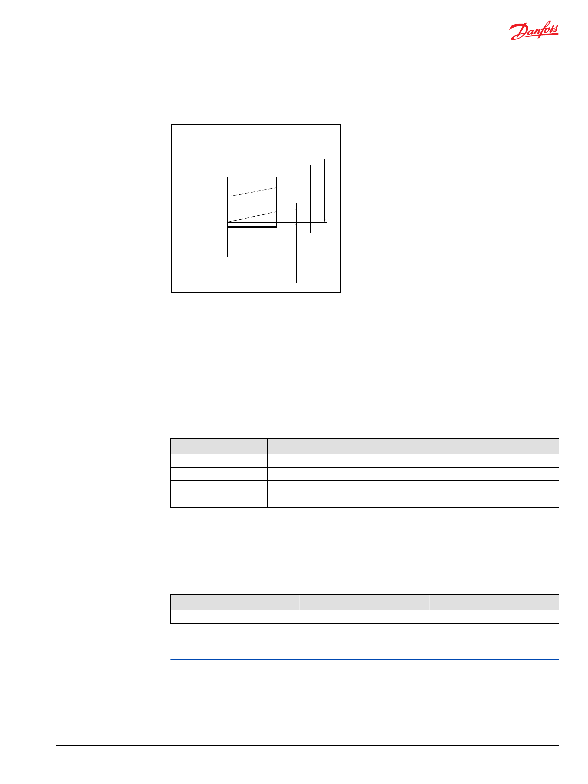
min.
[145 psi]
min. 10 bar
[510 psi]
max. 35 bar
max.
Displacement
Hydraulic
two-positioncontrol
PCOR start
setting range
Ramp < 10
[145]
130
[1890]
370 [5370]
Pressure compensator
override bar, [psi]
P001 776E
Technical Information
Series 51 and 51-1 Bent Axis Variable Displ. Motors
Controls circuit diagram – nomenclature – description
Control operation TH**
Option THC0: pressure compensator configuration with hydraulic BPD
A shuttle valve ahead of the pressure compensator prevents operation in the deceleration direction
(when motor is running in pump mode). This is designed to prevent rapid or uncontrolled deceleration
while the vehicle/machine is slowing down. Pressure compensator override with brake pressure defeat is
mainly used in systems with pumps having electric or hydraulic proportional controls or automotive
controls.
The shuttle valve must be controlled by a 2-line external signal, based on direction of motor rotation, see
the following table:
Pressure compensator operation
Motor rotation High pressure port Control pressure on port*PCOR function
CW A XA no
CW A XB yes
CCW B XA yes
CCW B XB no
*
Differencial control pressure between port XA / XB:
∆p
= 0.5 bar [7 psi]
min
∆p
= 50 bar [725 psi]
max
Option THC2: pressure compensator configuration without Brake Pressure Defeat
Pressure compensator functions when the motor is running in motor mode as well as in pump
(deceleration) mode.
Configuration option High pressure port PCOR function
THC2 A and B yes
Not all control options are shown in this Technical Information.
Contact your Danfoss representative for special control functions.
©
Danfoss | October 2017 520L0440 | BC00000018en-US0401 | 39
Page 40
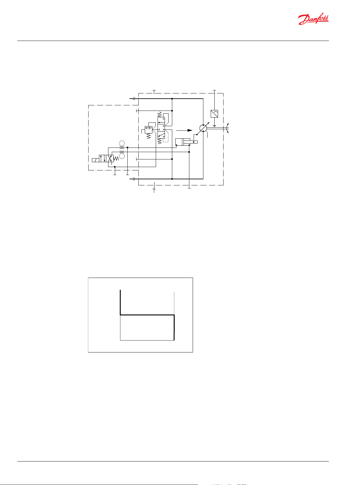
n
min.
disp.
T3
T2
M4
B
M3
M5
L1
N
L2
A
P001 780E
min
12V
/24V
max
Displacement
Control voltage
P001 870E
Electrohydraulic
two-position control
Technical Information
Series 51 and 51-1 Bent Axis Variable Displ. Motors
Controls circuit diagram – nomenclature – description
Options E1B1, E2B1, E7B1 – electrohydraulic two-position control for 51-1 (frame size 060, 080, 110)
Circuit diagram – motor with EH two-position control E1B1, E2B1, E7B1
A, B = Main pressure lines
L1, L2 = Drain lines
M3, M4 = Servo pressure
M5 = Gauge port servo supply pressure internal
T2, T3 = Optional orifices
N = Speed sensor
Displacement can be changed electrohydraulically under load from maximum displacement to minimum
displacement and vice versa, by using a built-in solenoid valve.
Control operation E1B1, E2B1, E7B1
Options:
Solenoid off = max. displacement
Solenoid on = min. displacement
Pilot pressure for solenoid:
internal = low pressure
The graph shows the necessary servo pressure (= low pressure), which is needed to stroke the motor,
depending on high system pressure and the pump or motor mode.
40 | © Danfoss | October 2017 520L0440 | BC00000018en-US0401
Page 41
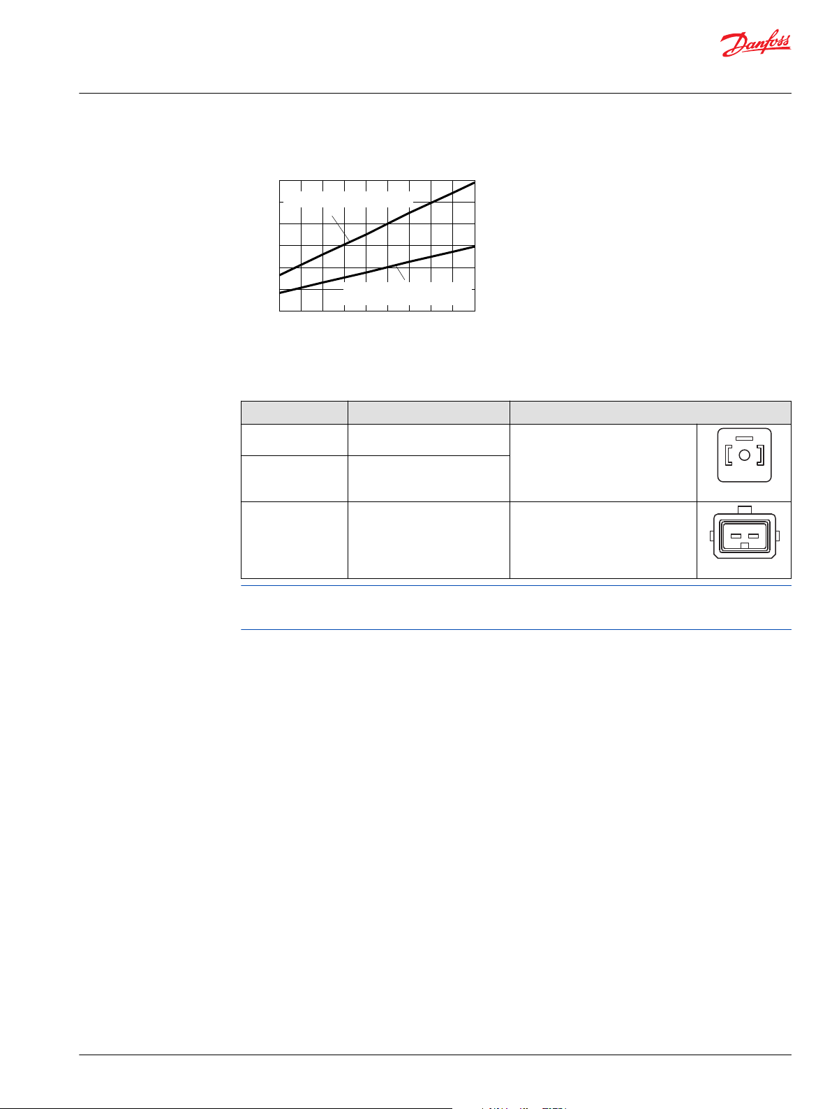
System pressure bar [psi]
Servo pressure bar [psi]
0
0
200
[2900]
100
[1450]
10
[145]
20
[290]
30
[435]
300
[4350]
400
[5800]
min. pilot pressure in pump mode
to shift from min to max angle
min. pilot pressure at all other
conditions motor and pump mode
in both directions
P001 878E
A B
P001752
2 1
P001751
Technical Information
Series 51 and 51-1 Bent Axis Variable Displ. Motors
Controls circuit diagram – nomenclature – description
Control E*B1 necessary low system pressure
E1B1, E2B1, E7B1 solenoid connectors
Configuration Voltage / Electric power
E1B1 12 VDC / 34 W
Solenoid plug face for DIN 46350
Mating connector No.: K09129
E2B1 24 VDC / 34 W
Id. No.: 514117
AMP Junior Timer two-pin
E7B1 12 VDC / 34 W
Mating connector No.: K19815
Id. No.: 508388
Not all control options are shown in this Technical Information.
Contact your Danfoss representative for special control functions.
Connector (supplied)
©
Danfoss | October 2017 520L0440 | BC00000018en-US0401 | 41
Page 42

n
max.
disp.
T3
T2
T1
T7 T8
P100 180E
B
M8
M7
M2
L1
M1
N
M3
M4
L2
A
M5
min
12V
/24V
max
Displacement
Control voltage
P001 870E
Electrohydraulic
two-position control
Technical Information
Series 51 and 51-1 Bent Axis Variable Displ. Motors
Controls circuit diagram – nomenclature – description
Options E1A5, E2A5 – electrohydraulic two-position control for 51 (frame size 160, 250)
Circuit diagram – motor with control options: E1A5, E2A5
Ports:
A, B = Main pressure lines
L1, L2 = Drain lines
M1, M2 = Gauge port for A and B
M3, M4 = Gauge port servo pressure
M5 = Gauge port servo supply pressure, internal
M7, M8 = Gauge port control pressure, internal
T1, T2, T3, T7, T8 = Optional orifices
N = Speed sensor
Displacement can be changed electrohydraulically under load from maximum displacement to minimum
displacement and vice versa, by using a built-in solenoid valve.
Control operation E1A5, E2A5
Options:
Solenoid off = max. displacement
Solenoid on = min. displacement
Pilot pressure for solenoid:
42 | © Danfoss | October 2017 520L0440 | BC00000018en-US0401
Page 43

A B
P001752
Technical Information
Series 51 and 51-1 Bent Axis Variable Displ. Motors
Controls circuit diagram – nomenclature – description
internal = low pressure
E1A5, E2A5 solenoid connectors
Configuration Voltage / Electric power
E1A5 12 VDC / 14.7 W
E2A5 24 VDC / 14.7 W
Solenoid plug face for DIN 46350
Mating connector No.: K09129
Id. No.: 514117
Not all control options are shown in this Technical Information.
Contact your Danfoss representative for special control functions.
Connector (Supplied)
©
Danfoss | October 2017 520L0440 | BC00000018en-US0401 | 43
Page 44
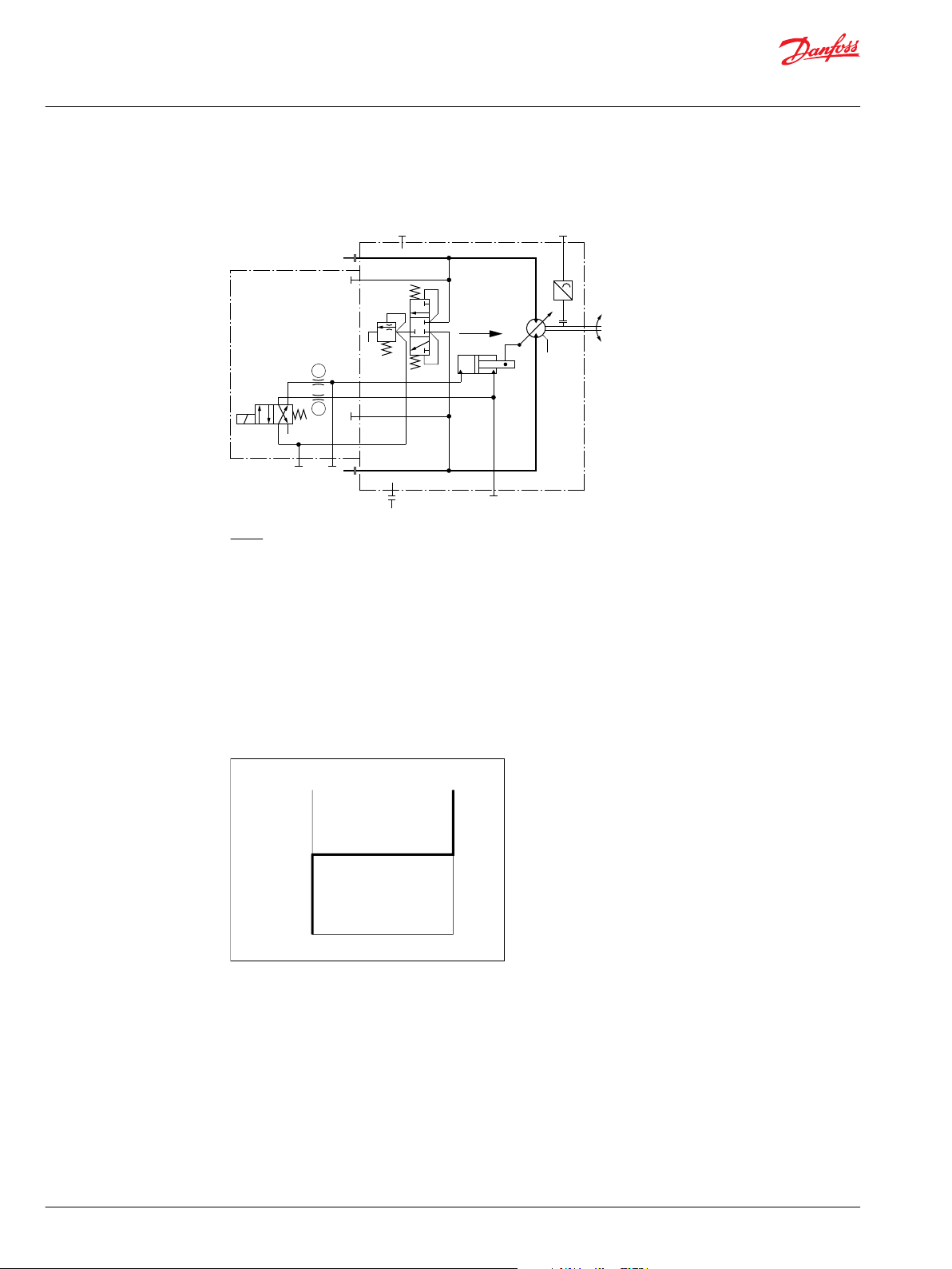
n
min.
disp.
T3
T2
M4
B
M3M5
L1
N
L2
A
P001 867E
min
12V
/24V
max
Displacement
Control voltage
Electrohydraulic
two-position control
P001 871E
Technical Information
Series 51 and 51-1 Bent Axis Variable Displ. Motors
Controls circuit diagram – nomenclature – description
Options F1B1, F2B1 – electrohydraulic two-position control for 51-1 (frame size 060, 080, 110)
Circuit diagram – motor with control options: F1B1, F2B1
Ports:
A, B = Main pressure lines
L1, L2 = Drain lines
M3, M4 = Servo pressure
M5 = Gauge port servo supply pressure internal
T2, T3 = Optional orifices
N = Speed sensor
Displacement can be changed electrohydraulically under load from maximum displacement to minimum
displacement and vice versa, by using a built-in solenoid valve.
Control operation F1B1, F2B1
Options:
Solenoid off = min. displacement
Solenoid on = max. displacement
Pilot pressure for solenoid:
internal = low pressure
The graph shows the necessary servo pressure (= low pressure), which is needed to stroke the motor,
depending on high system pressure and the pump or motor mode.
44 | © Danfoss | October 2017 520L0440 | BC00000018en-US0401
Page 45
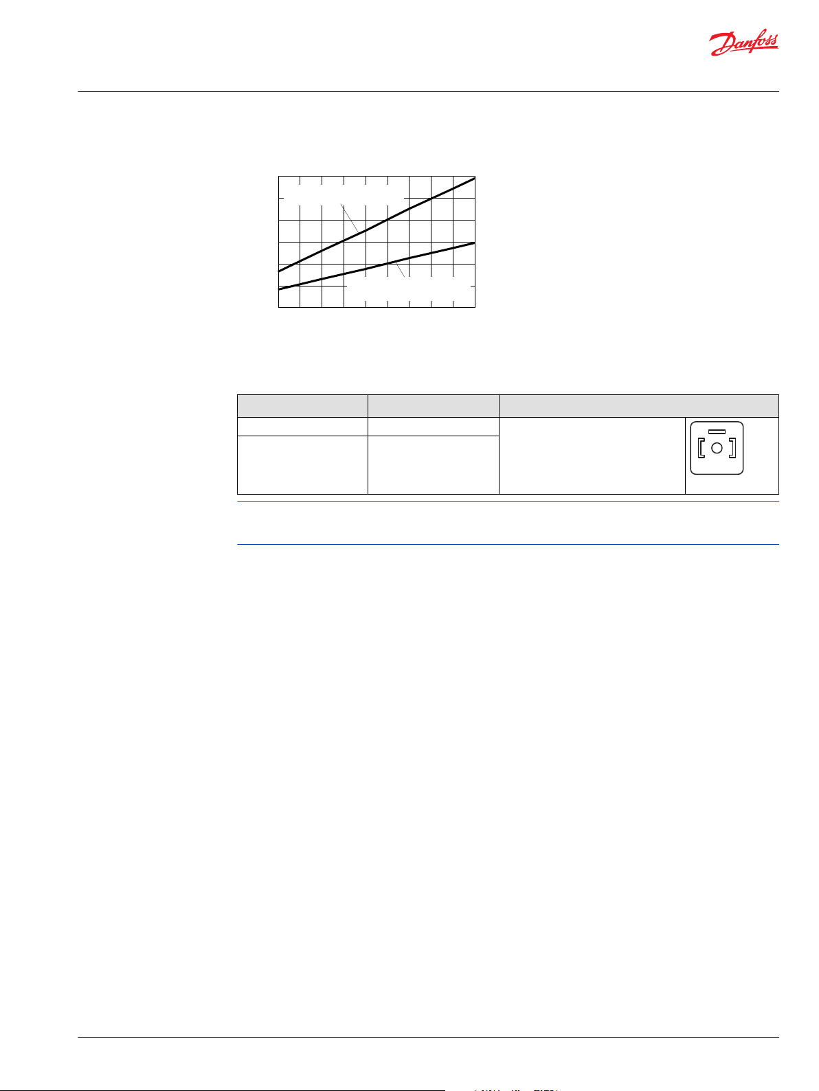
System pressure bar [psi]
Servo pressure bar [psi]
0
0
200
[2900]
100
[1450]
10
[145]
20
[290]
30
[435]
300
[4350]
400
[5800]
min. pilot pressure in pump mode
to shift from min to max angle
min. pilot pressure at all other
conditions motor and pump mode
in both directions
P001 879E
A B
P001752
Technical Information
Series 51 and 51-1 Bent Axis Variable Displ. Motors
Controls circuit diagram – nomenclature – description
Control F1B1, F2B1 necessary low system pressure
F1B1, F2B1 solenoid connectors
Configuration Voltage / Electric power
F1B1 12 VDC / 14.7 W
Solenoid plug face for DIN 46350
Mating connector No.: K09129
F2B1 24 VDC / 14.7 W
Id. No.: 514117
Not all control options are shown in this Technical Information.
Contact your Danfoss representative for special control functions.
Connector (Supplied)
©
Danfoss | October 2017 520L0440 | BC00000018en-US0401 | 45
Page 46

n
max.
disp.
T2T1T3
T7 T8
P001 874E
L2
M4
M3
N
M1
L1
M2
M7M8
B
A
M5
min
12V
/24V
max
Displacement
Control voltage
Electrohydraulic
two-position control
P001 871E
Technical Information
Series 51 and 51-1 Bent Axis Variable Displ. Motors
Controls circuit diagram – nomenclature – description
Options F1A5, F2A5 – electrohydraulic two-position control for 51 (frame size 160, 250)
Circuit diagram – motor with control options: F1A5, F2A5
Ports:
A, B = Main pressure lines
L1, L2 = Drain lines
M1, M2 = Gauge port for A and B
M3, M4 = Gauge port servo pressure
M5 = Gauge port servo supply pressure, internal
M7, M8 = Gauge port control pressure, internal
T1, T2, T3, T7, T8 = Optional orifices
N = Speed sensor
Displacement can be changed electrohydraulically under load from maximum displacement to minimum
displacement and vice versa, by using a built-in solenoid valve.
Control operation F1A5, F2A5
Options:
Solenoid off = min. displacement
Solenoid on = max. displacement
Pilot pressure for solenoid:
46 | © Danfoss | October 2017 520L0440 | BC00000018en-US0401
Page 47

A B
P001752
Technical Information
Series 51 and 51-1 Bent Axis Variable Displ. Motors
Controls circuit diagram – nomenclature – description
internal = low pressure
F1A5, F2A5 solenoid connectors
Configuration Voltage / Electric power
F1A5 12 VDC / 14.7 W
F2A5 24 VDC / 14.7 W
Solenoid plug face for DIN 46350
Mating connector No.: K09129
Id. No.: 514117
Not all control options are shown in this Technical Information.
Contact your Danfoss representative for special control functions.
Connector (Supplied)
©
Danfoss | October 2017 520L0440 | BC00000018en-US0401 | 47
Page 48

n
T3
min.
disp.
M4
L1
N
L2
A
B
M3
T3
M3
T3
M3
P001 784E
XB
XA
with Electric
brake pressure
defeat
with Hydraulic
brake pressure
defeat
without
Brake pressure
defeat
Technical Information
Series 51 and 51-1 Bent Axis Variable Displ. Motors
Controls circuit diagram – nomenclature – description
Options T1**, T2**, T7** – electrohydraulic two-position control for 51-1 (frame size 060, 080, 110)
Circuit diagram – motor with electrohydraulic two-position control T1**, T2**, T7**
Ports:
A, B = Main pressure lines
L1, L2 = Drain lines
M3, M4 = Gauge port servo pressure
XA, XB = Control pressure ports, brake pressure defeat
T3 = Optional orifices
N = Speed sensor
Displacement can be changed electrohydraulically under load from minimum displacement to maximum
displacement and vice versa, by using a solenoid. When the solenoid is energized the motor has
maximum displacement and the pressure compensator does not function.
Solenoid not energized = minimum displacement
Solenoid energized = maximum displacement
Pressure Compensator Override (PCOR)
The control can be overridden by PCOR using high loop pressure. When the PCOR activates, the motor
displacement increases toward maximum. Pressure ramp from PCOR start pressure (with motor at
minimum displacement) until maximum displacement is reached is less than 10 bar [145 psi]. This
ensures optimal power utilization throughout the entire displacement range of the motor.
PCOR start pressure is adjustable from 130 to 370 bar [1890 to 5370 psi].
48 | © Danfoss | October 2017 520L0440 | BC00000018en-US0401
Page 49

min.
12V/24V
max.
Displacement
Electrohydraulic
two-positioncontrol
PCOR start
setting range
Ramp <
10 [145]
130
[1890]
370 [5 370]
Pressure compensator
override bar, [psi]
P001 872E
Technical Information
Series 51 and 51-1 Bent Axis Variable Displ. Motors
Controls circuit diagram – nomenclature – description
Control operation T1**, T2**, T7**
Option T*CA: pressure compensator configuration with hydraulic Brake Pressure Defeat
A shuttle valve ahead of the pressure compensator prevents operation in the deceleration direction
(when motor is running in pump mode). This is designed to prevent rapid or uncontrolled deceleration
while the vehicle/machine is slowing down.
Pressure compensator override with brake pressure defeat is mainly used in systems with pumps having
electric or hydraulic proportional controls or automotive controls.
The shuttle valve must be controlled by a 2-line external signal, based on direction of motor rotation, see
the following table:
Motor rotation High pressure port Control pressure on port*PCOR function
CW A XA yes
CW A XB no
CCW B XA no
CCW B XB yes
*
Differencial control pressure between port XA/XB:
∆p
= 0.5 bar [7 psi]
min
∆p
= 50 bar [725 psi]
max
Options T*D1, T*D2, T* D7: pressure compensator configuration with electric BPD
A solenoid-switched valve ahead of the pressure compensator prevents operation in the deceleration
direction (when motor is running in pump mode). This is designed to prevent rapid or uncontrolled
deceleration while the vehicle/machine is slowing down.
The solenoid valve must be controlled by an external electric signal, based on direction of motor rotation,
see the following table:
Motor rotation High pressure port Solenoid PCOR function
CW A energized yes
CW A non energized no
CCW B energized no
CCW B non energized yes
©
Danfoss | October 2017 520L0440 | BC00000018en-US0401 | 49
Page 50

A B
P001752
2 1
P001751
Technical Information
Series 51 and 51-1 Bent Axis Variable Displ. Motors
Controls circuit diagram – nomenclature – description
T1D1, T2D2, T7D7 solenoid connectors
Configuration Voltage / Electric power
T1D1 12 VDC / 34 W
24 VDC / 34 W
T2D2
T7D7 12 VDC / 34 W
Solenoid plug face for DIN 46350
Mating connector No.: K09129
Id. No.: 514117
AMP Junior Timer two-pin
Mating connector No.: K19815
Id. No.: 508388
Connector (Supplied)
Option T*C2: pressure compensator configuration without Brake Pressure Defeat
Pressure compensator functions when the motor is running in motor mode as well as in pump
(deceleration) mode.
Configuration option High pressure port PCOR function
T*C2 A and B yes
Not all control options are shown in this Technical Information.
Contact your Danfoss representative for special control functions.
50 | © Danfoss | October 2017 520L0440 | BC00000018en-US0401
Page 51

n
T3T2
T1 T7 T8
max.
disp.
B
L2 M4 M3
N
M1
L1
M2
M5
A
P001 785E
X4
XB
XA
X4
with
Brake pressure
defeat
without
Brake pressure
defeat
Technical Information
Series 51 and 51-1 Bent Axis Variable Displ. Motors
Controls circuit diagram – nomenclature – description
Options T1**, T2** – electrohydraulic two-position control for 51 (frame size 160, 250)
Circuit diagram – motor with electrohydraulic two-position control T1**, T2**
Ports:
A, B = Main pressure lines
L1, L2 = Drain lines
M1, M2 = Gauge port for A and B
M3, M4 = Gauge port servo pressure
M5 = Gauge port servo supply
XA, XB = Control pressure ports, brake pressure defeat
T1, T2, T3, T7, T8 = Optional orifices
N = Speed sensor
Displacement can be changed electrohydraulically under load from minimum displacement to maximum
displacement and vice versa, by using a solenoid. When the solenoid is energized the motor has
maximum displacement and the pressure compensator does not function.
Solenoid not energized = minimum displacement
Solenoid energized = maximum displacement
Pressure Compensator OverRide (PCOR)
The control can be overridden by PCOR using high loop pressure. When the PCOR activates, the motor
displacement increases toward maximum. Pressure ramp from PCOR start pressure (with motor at
minimum displacement) until maximum displacement is reached is less than 10 bar [145 psi]. This
ensures optimal power utilization throughout the entire displacement range of the motor.
PCOR start pressure is adjustable from 130 to 370 bar [1890 to 5370 psi].
©
Danfoss | October 2017 520L0440 | BC00000018en-US0401 | 51
Page 52
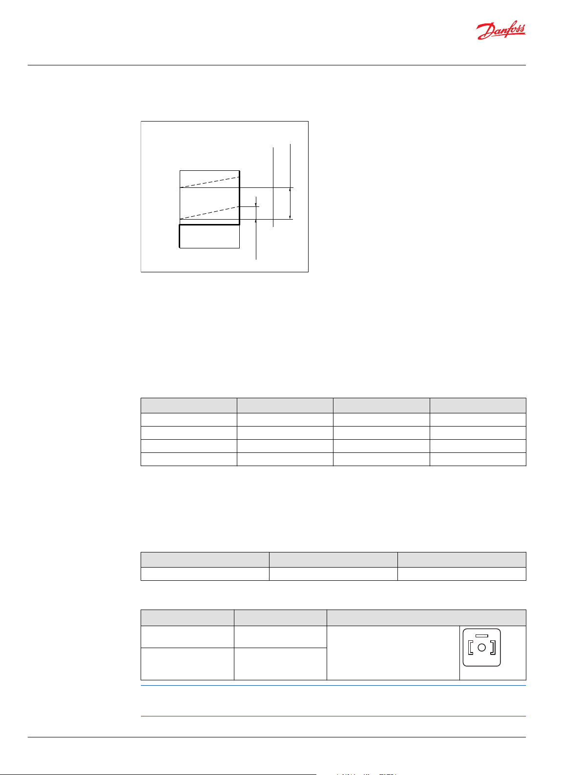
min.
12V/24V
max.
Displacement
Electrohydraulic
two-positioncontrol
PCOR start
setting range
Ramp <
10 [145]
130
[1890]
370 [5 370]
Pressure compensator
override bar, [psi]
P001 872E
A B
P001752
Technical Information
Series 51 and 51-1 Bent Axis Variable Displ. Motors
Controls circuit diagram – nomenclature – description
Control operation T1**, T2**
Option T*C0: pressure compensator configuration with hydraulic Brake Pressure Defeat
A shuttle valve ahead of the pressure compensator prevents operation in the deceleration direction
(when motor is running in pump mode). This is designed to prevent rapid or uncontrolled deceleration
while the vehicle/machine is slowing down. Pressure compensator override with brake pressure defeat is
mainly used in systems with pumps having electric or hydraulic proportional controls or automotive
controls.
The shuttle valve must be controlled by a 2-line external signal, based on direction of motor rotation, see
the following table:
Motor rotation High pressure port Control pressure on port*PCOR function
CW A XA no
CW A XB yes
CCW B XA yes
CCW B XB no
*
Differencial control pressure between port XA/XB:
∆p
= 0.5 bar [7 psi]
min
∆p
= 50 bar [725 psi]
max
Option T*C2: pressure compensator configuration without Brake Pressure Defeat
Pressure compensator functions when the motor is running in motor mode as well as in pump
(deceleration) mode.
Configuration option High pressure port PCOR function
T*C2 A and B yes
T1C2, T2C2 solenoid connectors
Configuration Voltage / Electric power
T1C2 12 VDC / 14.7 W
T2C2 24 VDC / 14.7 W
Solenoid plug face for DIN 46350
Mating connector No.: K09129
Id. No.: 514117
Connector (Supplied)
Not all control options are shown in this Technical Information.
Contact your Danfoss representative for special control functions.
52 | © Danfoss | October 2017 520L0440 | BC00000018en-US0401
Page 53

n
T3
T7T1 T8
T2
max.
disp.
A
L2 M4
M3
N
M1
L1
M2
M8
M7
X1
M5
B
WITH
BRAKE PRESSURE
DEFEAT
WITHOUT
BRAKE PRESSURE
DEFEAT
P001 786E
T4
T6
U6
U7
T5
XA
XB
U6
U7
T5
Technical Information
Series 51 and 51-1 Bent Axis Variable Displ. Motors
Controls circuit diagram – nomenclature – description
Options EP**, EQ** – electrohydraulic proportional control for 51 (all frame sizes)
Circuit diagram – motor with electrohydraulic proportional control EP**, EQ**
Ports:
A, B = Main pressure lines
L1, L2 = Drain lines
M1, M2 = Gauge port for A and B
M3, M4 = Gauge port servo pressure
M5 = Gauge port servo supply pressure internal
M7, M8 = Gauge port control pressure internal
X1 = Port for control supply pressure external
XA, XB = Control pressure ports, BPD
T1, T2, T3,T4, T5, T6,T7, T8, U6, U7 = Optional orifices
N = Speed sensor
Displacement can be changed under load in response to an electrical signal between maximum
displacement and minimum displacement and vice versa.
Control start = maximum displacement
Control end = minimum displacement
Control supply pressure (port X1)
p
= 20 bar [290 psi]
min
p
max allowable
= 70 bar [1015 psi]
©
Danfoss | October 2017 520L0440 | BC00000018en-US0401 | 53
Page 54

Control start
setting range
Ramp
min
max
50
158550
Current mA
Displacement
J
K
Proportional
control
PCOR start
setting range
Ramp < 10 bar
[145 psi]
370 [5370]
130
[1890]
High pressure Dp bar [psi]
Pressure compensator
override
Control start
version
P001 172E
A
B
D
C
MS Connector
MS3102C-14S-2P
(Supplied Connector)
Mating Connector
No.: K08106
Id.-No.: 615062
P001 753E
Packard Weather-Pack
4 pin
(Supplied Connector)
Mating Connector
No.: K03384
Id.-No.: 712208
A
B
C
D
P001 759E
Technical Information
Series 51 and 51-1 Bent Axis Variable Displ. Motors
Controls circuit diagram – nomenclature – description
Control operation EP**, EQ**
Control setting options
Type
JY
JW 95 mA
KY
KW 95 mA
*
Max. current = 250 mA
**
from max. to min. displacement; full stroke current.
Start current (adjustable)*Standard setting: control
15 to 50 mA 30 = 30 mA
50 to 85 mA 70 = 70 mA
start
Ramp
70 mA
70 mA
**
Coil wiring
Single
Coil resistance = 26 Ω
Connectors
Wiring (maximum to minimum displacement)
Coil wiring Positive voltage on pin Ground on pin
Single coil B A
Single coil (alt.) D C
Pressure Compensator Override (PCOR)
The control can be overridden by PCOR using high loop pressure.
54 | © Danfoss | October 2017 520L0440 | BC00000018en-US0401
When the PCOR activates, the motor displacement increases to maximum.
Pressure ramp from PCOR start pressure (with motor at minimum displacement) until maximum
displacement is reached is less than 10 bar [145 psi] . This ensures optimal power utilization throughout
the entire displacement range of the motor.
PCOR start pressure is adjustable from 130 to 370 bar [1890 to 5370 psi].
Page 55
Technical Information
Series 51 and 51-1 Bent Axis Variable Displ. Motors
Controls circuit diagram – nomenclature – description
Configuration option PCOR at port BPD function
EPA1/EQA1 A and B with
EPA2/EQA2 A and B without
Options EPA1, EQA1: pressure compensator configuration with Brake Pressure Defeat
A shuttle valve ahead of the pressure compensator prevents operation in the deceleration direction
(when motor is running in pump mode). This is designed to prevent rapid or uncontrolled deceleration
while the vehicle/machine is slowing down.
Pressure compensator override with brake pressure defeat is mainly used in systems with pumps having
electric or hydraulic proportional controls or automotive controls.
The shuttle valve must be controlled by a 2-line external signal, based on direction of motor rotation, see
the following table:
Pressure compensator operation
Motor rotation High pressure port Control pressure on port*PCOR function
CW A XA no
CW A XB yes
CCW B XA yes
CCW B XB no
*
Differencial control pressure between port XA/XB:
∆p
= 0.5 bar [7 psi]
min
∆p
= 50 bar [725 psi]
max
Options EPA2, EQA2: pressure compensator configuration without Brake Pressure Defeat
The pressure compensator override functions when the motor is running in motor mode as well as in
pump (deceleration) mode.
Not all control options are shown in this Technical Information.
Contact your Danfoss representative for special control functions.
©
Danfoss | October 2017 520L0440 | BC00000018en-US0401 | 55
Page 56

n
T1
T2
T3
T7 T8
max.
disp.
P001 787E
B
A
L2 M4
M3
N
M1
M5
L1
M2
1290
440
0
645
220
0
20%
min
100%
max
Control current (mA)
Control current (mA)
Displacement
Electrohydraulic proportional control
L7**
L8**
P001 777E
Technical Information
Series 51 and 51-1 Bent Axis Variable Displ. Motors
Controls circuit diagram – nomenclature – description
Options L1B1, L2B1, L7B1 – electrohydraulic proportional control for 51 (all frame sizes)
Circuit diagram – motor with electrohydraulic propor. control L1B1, L2B1, L7B1
Ports:
A, B = Main pressure lines
L1, L2 = Drain lines
M1, M2 = Gauge port for A and B
M3, M4 = Gauge port servo pressure
M5 = Gauge port servo supply pressure internal
T1, T2, T3,T7, T8 = Optional orifices
N = Speed sensor
Displacement can be changed electrohydraulically under load in response to an electrical signal from
minimum displacement to maximum displacement and vice versa. The displacement changes
proportional to the electrical signal. The electrical signal must be a pulse-width modulated (PWM) signal,
(f = 100...200 Hz).
Control start = maximum displacement
Control end = minimum displacement
Control operation L1**, L2**, L7**
56 | © Danfoss | October 2017 520L0440 | BC00000018en-US0401
Page 57

A B
P001752
2 1
P001751
Technical Information
Series 51 and 51-1 Bent Axis Variable Displ. Motors
Controls circuit diagram – nomenclature – description
L1B1, L2B1, L7B1 solenoid connectors
Solenoid plug face DIN 46350 (Supplied) AMP Junior Timer two-pin (Supplied)
Mating connector No.: K09129
Id. No.: 514117
Mating connector No.: K19815
Id. No.: 508388
Solenoid data
Configuration Voltage Nominal
L1B1
L7B1 AMP Junior Timer
L2B1 24 V
12 V
resistance 20 °C
5.7 Ω 440 mA 1290 mA 1500 mA
DC
21.3 Ω 220 mA 645 mA 750 mA DIN 46350
DC
Start End Max.
Control current Connector
DIN 46350
Not all control options are shown in this Technical Information.
Contact your Danfoss representative for special control functions.
©
Danfoss | October 2017 520L0440 | BC00000018en-US0401 | 57
Page 58

n
T4
T6
T2
T3
T1
T7 T8
U7
max.
disp.
B
XB
XA
M7
A
L2
M4 M3
N
M1
L1
M2
(M5)
X3
P001 869E
Technical Information
Series 51 and 51-1 Bent Axis Variable Displ. Motors
Controls circuit diagram – nomenclature – description
Options D7M1, D8M1 – electrohydraulic proportional control with PCOR and hydraulic BPD for 51 (all frame sizes)
Circuit diagram – motor with EH prop. control D7M1, D8M1
Ports:
A, B = Main pressure lines
L1, L2 = Drain lines
M1, M2 = Gauge port for A and B
M3, M4 = Gauge port servo pressure
X3 (M5) = Servo pressure supply
M7 = Gauge port control pressure
XA, XB = Control pressure ports, hydraulic BPD
T1, T2, T3,T4, T6,T7, T8, U7 = Optional orifices
N = Speed sensor
Displacement can be changed electrohydraulically under load in response to an electrical signal from
minimum displacement to maximum displacement and vice versa. The displacement changes
proportional to the electrical signal. The electrical signal must be a pulse-width modulated (PWM) signal,
(f = 100...200 Hz).
Solenoid not energized = maximum displacement
Solenoid energized = minimum displacement
Servo pressure supply = external pressure at port X3
Min. pressure = 25 bar [360 psi]
Max. pressure = 50 bar [725 psi]
Pressure Compensator Override (PCOR)
The control can be overridden by PCOR using high loop pressure.
When the PCOR activates, the motor displacement increases to maximum. Pressure ramp from PCOR start
pressure (with motor at minimum displacement) until maximum displacement is reached is less than 10
bar [145 psi]. This ensures optimal power utilization throughout the entire displacement range of the
motor.
PCOR start pressure is adjustable from 130 to 370 bar [1890 to 5370 psi].
58 | © Danfoss | October 2017 520L0440 | BC00000018en-US0401
Page 59

Ramp
(ratio 5:1)
min
max
start-current
end-current
320 640
594
D8M1 D7M1
1188
Displacement
Electrohydr.
prop. control
PCOR start
setting range
Pressure compensator
override
370 bar
[5370 psi]
130 bar
[1890 psi]
Ramp < 10 bar
[145 psi]
Control current (mA)
P001 873E
A B
P001752
Technical Information
Series 51 and 51-1 Bent Axis Variable Displ. Motors
Controls circuit diagram – nomenclature – description
Control operation D7M1, D8M1
Options D7M1, D8M1: pressure compensator configuration with hydraulic Brake Pressure Defeat
A shuttle valve ahead of the pressure compensator prevents operation in the deceleration direction
(when motor is running in pump mode). This is designed to prevent rapid or uncontrolled deceleration
while the vehicle/machine is slowing down.
Pressure compensator override with brake pressure defeat is mainly used in systems with pumps having
electric or hydraulic proportional controls or automotive controls.
The shuttle valve must be controlled by a 2-line external signal, based on direction of motor rotation, see
the following table:
©
Danfoss | October 2017 520L0440 | BC00000018en-US0401 | 59
Motor rotation High pressure port Control pressure on port*PCOR function
CW A XA no
CW A XB yes
CCW B XA yes
CCW B XB no
*
Differencial control pressure between port XA/XB:
∆p
= 0.5 bar [7 psi]
min
∆p
= 50 bar [725 psi]
max
D7M1, D8M1 solenoid connector
Solenoid connector
Plug face DIN 46350 (Supplied)
Mating connector No.: K09129
Id. No.: 514117
Configuration Voltage Nominal
D7M1 12 V
D8M1 24 V
resistance 20 °C
5.7 Ω 640 mA 1188 mA 1500 mA
DC
21.2 Ω 320 mA 594 mA 750 mA
DC
Start End Max.
Control current Connector
AMP Junior Timer
two-pin
Not all control options are shown in this Technical Information.
Contact your Danfoss representative for special control functions.
Page 60

T4
T6
U6
U7
T5
XA
XB
with
Brake pressure
defeat
without
Brake pressure
defeat
U6
U7
T5
n
T3
T7T1 T8
T2
max.
disp.
A
L2 M4
M3
N
M1
L1
M2
P001 788E
M5
B
M7
X1
Technical Information
Series 51 and 51-1 Bent Axis Variable Displ. Motors
Controls circuit diagram – nomenclature – description
Options HS** – hydraulic proportional control for 51 (all frame sizes)
Circuit diagram – motor with hydraulic proportional control HS**
A, B = Main pressure lines M7 = Gauge port control pressure
L1, L2 = Drain lines X1 = Port for control supply pressure external
M1, M2 = Gauge port for A and B XA, XB = Control pressure ports, BPD
M3, M4 = Gauge port servo pressure T1, T2, T3,T4, T5, T6,T7, T8, U6, U7 = Optional orifices
M5 = Gauge port servo supply pressure N = Speed sensor
Displacement can be changed in response to a hydraulic signal under load between maximum
displacement and minimum displacement and vice versa.
Control start = maximum displacement
Control end = minimum displacement
Control pressure (Port X1)
External = absolute pressure
Control start setting range (pressure above case pressure)
p
start
P
max allowable
Control ramp
From 100% to 20% displacement 7 bar [102 psi]
From 100% to 20% displacement 14 bar [203 psi]
3 to 5 bar [44 to 73 psi]
5 to 12 bar [73 to 175 psi]
12 to 30 bar [175 to 435 psi]
control start pressure + 50 bar [725 psi]
60 | © Danfoss | October 2017 520L0440 | BC00000018en-US0401
Pressure Compensator OverRide (PCOR)
The control can be overridden by PCOR using high loop pressure. When the PCOR activates, the motor
displacement increases to maximum. Pressure ramp from PCOR start pressure (with motor at minimum
displacement) until maximum displacement is reached is less than 10 bar [145 psi] . This ensures optimal
Page 61

Control start
setting range
Ramp
min
Control pressure D bar [psi]
Displacement
A
Proportional
control
PCOR start
setting range
Ramp < 10 bar
[145 psi]
370 [5370]
130
[1890]
High pressure D p bar [psi]
Pressure compensator
override
Control start
version
5 [73]
12 [175]
30 [435]
3 [44]
5 [73]
12 [175]
B C
max
P001 171E
Technical Information
Series 51 and 51-1 Bent Axis Variable Displ. Motors
Controls circuit diagram – nomenclature – description
power utilization throughout the entire displacement range of the motor. PCOR start pressure is
adjustable from 130 to 370 bar [1890 to 5370 psi].
Control Operation HS**
Configuration PCOR at port BPD function
HSA1 A and B with
HSA2 A and B without
Option HSA1: pressure compensator configuration with Brake Pressure Defeat
A shuttle valve ahead of the pressure compensator prevents operation in the deceleration direction
(when motor is running in pump mode). This is designed to prevent rapid or uncontrolled deceleration
while the vehicle/machine is slowing down. Pressure compensator override with brake pressure defeat is
mainly used in systems with pumps having electric or hydraulic proportional controls or automotive
controls.
The shuttle valve must be controlled by a 2-line external signal, based on direction of motor rotation, see
the following table:
Motor rotation High pressure port Control pressure on port*PCOR function
CW A XA no
CW A XB yes
CCW B XA yes
CCW B XB no
*
Differencial control pressure between port XA/XB:
∆p
= 0.5 bar [7 psi]
min
∆p
= 50 bar [725 psi]
max
Option HSA2: pressure compensator configuration without Brake Pressure Defeat
The pressure compensator override functions when the motor is running in motor mode as well as in
pump (deceleration) mode.
Not all control options are shown in this Technical Information.
©
Danfoss | October 2017 520L0440 | BC00000018en-US0401 | 61
Contact your Danfoss representative for special control functions.
Page 62

T2
T3
T7 T8
T1
max.
disp.
M2
X1
M7
B
M5
L1
M1
M4L2
A
M3
N
P001 880E
n
Technical Information
Series 51 and 51-1 Bent Axis Variable Displ. Motors
Controls circuit diagram – nomenclature – description
Option HZB1 – hydraulic proportional control for 51 (all frame sizes)
Circuit diagram – motor with hydraulic propor. control HZB1
A, B = Main pressure lines
L1, L2 = Drain lines
M1, M2 = Gauge port for A and B
M3, M4 = Gauge port servo pressure
M5 = Gauge port servo supply pressure internal
M7 = Gauge port control pressure
X1 = Control pressure port
T1, T2, T3, T7, T8 = Optional orifices
N = Speed sensor
Displacement can be changed in response to a hydraulic signal under load between maximum
displacement and minimum displacement and vice versa.
Control start = maximum displacement
Control end = minimum displacement
Control pressure on port X1
External = absolute pressure
62 | © Danfoss | October 2017 520L0440 | BC00000018en-US0401
Page 63

Control start
Setting range
Ramp
min
max
Control pressure D bar [psi]
Displacement
A
Proportional
control
Control start
version
5 [73]
12 [175]
30 [435]
3 [44]
5 [73]
12 [175]
B C
P001 881E
Technical Information
Series 51 and 51-1 Bent Axis Variable Displ. Motors
Controls circuit diagram – nomenclature – description
Control Operation HZB1
Control start setting range (pressure above case pressure)
p
start
P
max allowable
3 to 5 bar [44 to 73 psi]
5 to 12 bar [73 to 175 psi]
12 to 30 bar [175 to 435 psi]
control start pressure + 50 bar [725 psi]
Control ramp
From 100% to 20% displacement 7 bar [102 psi]
From 100% to 20% displacement 14 bar [203 psi]
Not all control options are shown in this Technical Information.
Contact your Danfoss representative for special control functions.
©
Danfoss | October 2017 520L0440 | BC00000018en-US0401 | 63
Page 64

P001 790E
88.5
[3.48]
88.5
[3.48]
40.0
[1.57].
19°
Loop flushing
shuttle valve
Charge pressure
relief valve
min. angle stop
adjustment
215.0
[8.45]
260.1 max.
[10.24 max.]
74.5
[2.93]
74.5
[2.93]
208.5
[8.21]
98.3
[3.87]
Split flange boss “A”+”B”
DN 19 typ II 40 MPa series
per ISO 6162 [SAE 0.75]
4 thread: 0.375-16UNC-2B
[3/8 -16UNC-2B]
19 [0.75] min.
full thread depth
A
B
M4
70.0
[2.76]
70.0
[2.76]
Case drain “L1”
1.0625-12UN-2B
[1 1/
16
-12UN-2B]
Alternate position
Case drain “L2”
1.0625-12UN-2B
[1 1/
16
-12UN-2B]
50.8
[2.00]
23.8
[0.94]
Gauge port “M1”
System pressure “A”
0.875-14UNF-2B
[7/8 -14UNF-2B]
Gauge port “M2”
System pressure “B”
0.875-14UNF-2B
[7/8 -14UNF-2B]
49.0
[1.94]
103.0
[4.05]
242.0
[9.53]
121.0
[4.77]
A
B
M4
47.0
[1.85]
50.8
[2.00]
73.0
[2.87]
73.0
[2.87]
47.0
[1.85]
23.8
[0.94]
Gauge ports “M1”+”M2”
System pressure “A”+”B”
0.5625-18UNF-2B
[9/
16
-18UNF-2B]
Split flange boss “A”
DN 19 typ II 40 MPa series
per ISO 6162 [SAE 0.75]
4 thread: 0.375-16UNC-2B
[3/8 -16UNC-2B]
19 [0.75] min.
full thread depth
Split flange boss “B”
DN 19 typ II 40 MPa series
per ISO 6162 [SAE 0.75]
4 thread: 0.375-16UNC-2B
[3/8 -16UNC-2B]
19 [0.75] min.
full thread depth
Y
Y
X
X
W
W
Y
Y
Gauge port “M4”
System pressure max. angle
0.5625-18UNF-2B
[9/
16
-18UNF-2B]
W
Gauge port “M4”
System pressure max. angle
0.5625-18UNF-2B
[9/
16
-18UNF-2B]
W
Technical Information
Series 51 and 51-1 Bent Axis Variable Displ. Motors
General dimensions – frame size 060
SAE flange design per ISO 3019/1
51V060-1 Two Position Control, N1NN (Side port on top, Axial port below)
64 | © Danfoss | October 2017 520L0440 | BC00000018en-US0401
Page 65

A
M3
M1
M5
L1
L2
L1
L2
263.0
[10.35]
121.0
[4.77]
P001 965E
56.0
[2.22]
103.0
[4.05]
Y
X
88.5
[3.48]
88.5
[3.48]
294.0
[11.56]
74.5
[2.93]
74.5
[2.93]
172
[6.77]
96
[3.77]
41
[1.60]
217
[8.53]
19°
50.80
[2.00]
Y
23.90
[0.94]
X
U
98 max.
[3.87] max.
Supply pressure
Shuttle valve
0.5625-18UNF-2B
[9/
16
-18UNF-2B]
Gauge port “M4”
Servo pressure max. angle
0.5625-18UNF-2B
[9/
16
-18UNF-2B]
W
W
M4
Shaft centerline
Control pressure port “X1”
0.5625-18UNF-2B
[9/
16
-18UNF-2B]
U
X1
M7
49.0
[1.93]
Supply pressure
Shuttle valve
0.5625-18UNF-2B
[9/
16
-18UNF-2B]
Gauge port “M4”
Servo pressure max. angle
0.5625-18UNF-2B
[9/
16
-18UNF-2B]
W
W
M4
45.0
[1.77]
45.0
[1.77]
70.0
[2.76]
70.0
[2.76]
50.80
[2.00]
B
A
M5
M3
M4
23.80
[0.94]
Y
Split flange boss “A”
DN 19 typ II 40 MPa series
per ISO 6162 [SAE 0.75]
4 thread: 0.375-16UNC-2B
[3/8 -16UNC-2B]
19 [0.75] min.
full thread depth
Split flange boss “B”
DN 19 typ II 40 MPa series
per ISO 6162 [SAE 0.75]
4 thread: 0.375-16UNC-2B
[3/8 -16UNC-2B]
19 [0.75] min.
full thread depth
Gauge port “M1”+”M2”
System pressure “A”+”B”
0.5625-18UNF-2B
[9/
16
-18UNF-2B]
66
[2.60]
66
[2.60]
Y
Gauge port “M2”
System pressure “B”
0.5625-18UNF-2B
[9/
16
-18UNF-2B]
Gauge port “M1”
System pressure “A”
0.5625-18UNF-2B
[9/
16
-18UNF-2B]
Gauge port “M5”
Servo pressure supply
0.5625-18UNF-2B
[9/
16
-18UNF-2B]
Control mounting
surface
Split flange boss “A”+”B”
DN 19 typ II 40 MPa series
per ISO 6162 [SAE 0.75]
4 thread: 0.375-16UNC-2B
[3/8 -16UNC-2B]
19 [0.75] min.
full thread depth
min. angle stop
adjustment
Gauge port “M7”
Control pressure
0.5625-18UNF-2B
[9/
16
-18UNF-2B]
Alternate position
Case drain “L2”
1.0625-12UN-2B
[1 1/
16
-12UN-2B]
Gauge port “M3”
Servo pressure min. angle
0.5625-18UNF-2B
[9/
16
-18UNF-2B]
Control start
adjustment
Loop flushing
shuttle valve
Charge pressure
relief valve
Case drain “L1”
1.0625-12UN-2B
[1 1/
16
-12UN-2B]
Technical Information
Series 51 and 51-1 Bent Axis Variable Displ. Motors
General dimensions – frame size 060
51V060 Proportional and Two Position Control, HZB1 (Side port on top, Axial port below)
©
Danfoss | October 2017 520L0440 | BC00000018en-US0401 | 65
Page 66
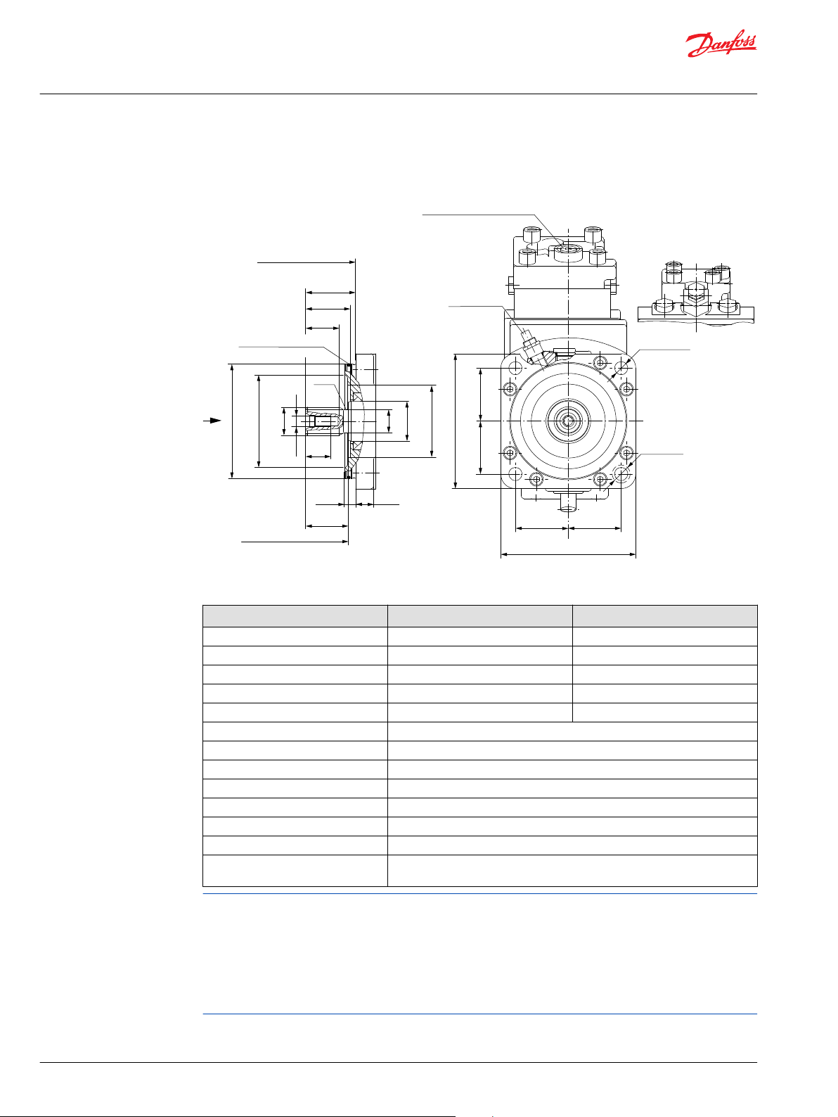
Ø126.975 ± 0.025
[4.999 ± 0.001]
Ø80.0
[3.15]
Ø44.45
[1.75]
ØG
ØD
ØA
Ø103.4
[4.07]
H
F
Mounting flange surface
flange 127-4 (SAE "C")
per ISO 3019/1
E
B
C
Coupling may not protrude
beyond this surface
12.45
[0.49]
18.0
[0.71]
P001 809E
57.25 ± 0.2
[2.25 ± 0.01]
57.25 ± 0.2
[2.25 ± 0.01]
57.25 ± 0.2
[2.25 ± 0.01]
4x Ø14.3 ± 0.2
[0.56 ± 0.01]
57.25 ± 0.2
[2.25 ± 0.01]
146.0 ± 1.6
[5.75 ± 0.06]
146.0 ± 1.6
[5.75 ± 0.06]
Speed pick-up
Ø19.5 [0.77]
other side max
screw head space
R3.0
[0.12]
Control pressure port “X1(M3)”
Servo pressure min. angle
0.5625-18UNF-2B
[9/
16
-18UNF-2B]
O-ring 3.00x116.00 FPM
[0.12x4.57]
X
Z
Series 51 with
HZB1-control
Z
Series 51-1 with
N1NN-control
Z
Technical Information
Series 51 and 51-1 Bent Axis Variable Displ. Motors
General dimensions – frame size 060
Shaft options – 51V060-1 and 51V060
Shaft spline data - mm [in]
Shaft option S1 C6
Number of teeth 14 21
Pitch 12/24 16/32
Pitch Ø 29.633 [1.167] 33.337 [1.312]
Ø A 31.15 [1.23] 34.43 [1.36]
Ø D 25.8 [1.02] 30.0 [1.18]
Pressure angle 30°
B 37.5 [1.476]
C 47.5±0.5 [1.87]
E 50.3±1.2 [1.98]
F 55.5±0.7 [2.19]
H 28.0 [1.1]
Spline ANSI B92.1-1970, class 5, flat root side fit
Ø G 0.4375-14UNC-2B [7/16-14UNC-2B]; allowed torque in thread max. 91 N•m
[805 lbf•in]
Flow into port A results in CW rotation of output shaft.
Flow into port B results in CCW rotation of output shaft.
Shaft rotation is determined by viewing from shaft end. Ports with O-ring seal and inch threads shall be in
accordance with ISO 11926/1.
Splite flange boss A and B per ISO 6162 is identical with high pressure series SAEJ518 code 62 (6000 psi).
Contact your Danfoss representative for specific installation drawings.
66 | © Danfoss | October 2017 520L0440 | BC00000018en-US0401
Page 67

P001 791E
49.0
[1.94]
94.0
[3.70]
218.0
[8.57]
87.0
[3.41]
90.0
[3.54]
59.0
[2.32]
40.0
[1.57]
19°
190.0
[7.49]
234.1 max.
[9.22 max.]
77.5
[3.05]
75.5
[2.97]
208.5
[8.21]
98.9
[3.89]
23.8
[0.94]
A
B
M4
47.0
[1.85]
50.8
[2.00]
73.0
[2.87]
73.0
[2.87]
47.0
[1.85]
23.8
[0.94]
Split flange boss “A”
DN 19 typ II 40 MPa series
per ISO 6162 [SAE 0.75]
4 thread: 0.375-16UNC-2B
[3/8 -16UNC-2B]
19 [0.75] min.
full thread depth
Split flange boss “B”
DN 19 typ II 40 MPa series
per ISO 6162 [SAE 0.75]
4 thread: 0.375-16UNC-2B
[3/8 -16UNC-2B]
19 [0.75] min.
full thread depth
W
Y
Gauge port “M4”
System pressure max. angle
0.5625-18UNF-2B
[9/
16
-18UNF-2B]
W
A
B
M4
70.0
[2.76]
70.0
[2.76]
Gauge port “M1”
System pressure “A”
0.875-14UNF-2B
[7/8 -14UNF-2B]
Gauge port “M2”
System pressure “B”
0.875-14UNF-2B
[7/8 -14UNF-2B]
W
Y
Gauge port “M4”
System pressure max. angle
0.5625-18UNF-2B
[9/
16
-18UNF-2B]
W
Loop flushing
shuttle valve
Charge pressure
relief valve
min. angle stop
adjustment
Split flange boss “A”+”B”
DN 19 typ II 40 MPa series
per ISO 6162 [SAE 0.75]
4 thread: 0.375-16UNC-2B
[3/8 -16UNC-2B]
19 [0.75] min.
full thread depth
Case drain “L1”
1.0625-12UN-2B
[1 1/
16
-12UN-2B]
Alternate position
Case drain “L2”
1.0625-12UN-2B
[1 1/
16
-12UN-2B]
Y
X
Y
X
Gauge ports “M1”+”M2”
System pressure “A”+”B”
0.5625-18UNF-2B
[9/
16
-18UNF-2B]
50.8
[2.00]
Technical Information
Series 51 and 51-1 Bent Axis Variable Displ. Motors
General dimensions – frame size 060
DIN flange design per ISO 3019/2
51D060-1 two position control, N1NN (Side port on top, Axial port below)
©
Danfoss | October 2017 520L0440 | BC00000018en-US0401 | 67
Page 68
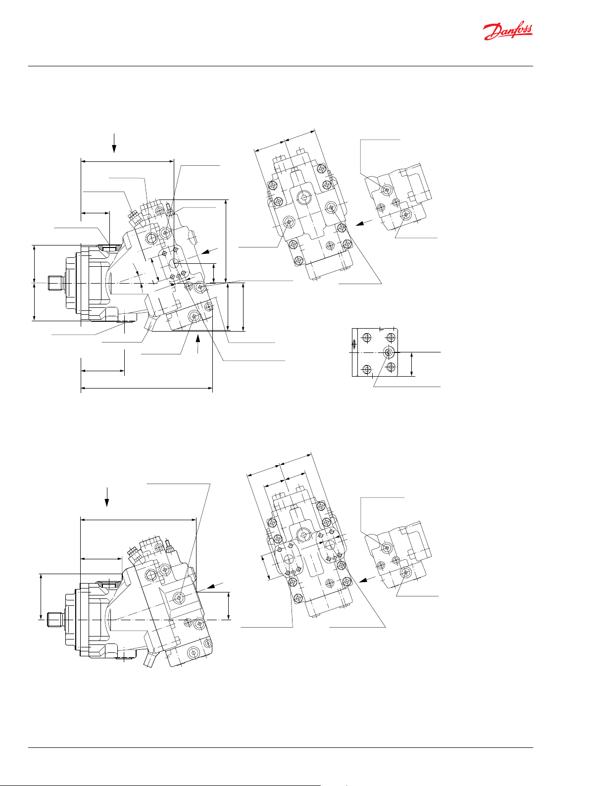
A
M3
M1
M5
L1
L2
45.0
[1.77]
45.0
[1.77]
50.80
[2.00]
70.0
[2.76]
70.0
[2.76]
Y
Split flange boss “A”
DN 19 typ II 40 MPa series
per ISO 6162 [SAE 0.75]
4 thread: 0.375-16UNC-2B
[3/8 -16UNC-2B]
19 [0.75] min.
full thread depth
Split flange boss “B”
DN 19 typ II 40 MPa series
per ISO 6162 [SAE 0.75]
4 thread: 0.375-16UNC-2B
[3/8 -16UNC-2B]
19 [0.75] min.
full thread depth
Gauge port “M1”+”M2”
System pressure “A”+”B”
0.5625-18UNF-2B
[9/
16
-18UNF-2B]
238.0
[9.39]
56.0
[2.22]
94.0
[3.70]
87.0
[3.45]
Y
X
90.0
[3.54]
59.0
[2.32]
Control start
adjustment
Gauge port “M3”
Servo pressure min. angle
0.5625-18UNF-2B
[9/
16
-18UNF-2B]
Gauge port “M5”
Servo pressure supply
0.5625-18UNF-2B
[9/
16
-18UNF-2B]
Control mounting
surface
P001 966E
Loop flushing
shuttle valve
270.0
[10.64]
77.5
[3.05]
75.5
[2.97]
172.0
[6.77]
96.0
[3.77]
41.0
[1.60]
192.0
[7.56]
19°
Case drain “L1”
1.0625-12UN-2B
[1 1/
16
-12UN-2B]
50.80
[2.00]
Y
23.90
[0.94]
X
U
Split flange boss “A”+”B”
DN 19 typ II 40 MPa series
per ISO 6162 [SAE 0.75]
4 thread: 0.375-16UNC-2B
[3/8 -16UNC-2B]
19 [0.75] min.
full thread depth
Gauge port “M7”
Control pressure
0.5625-18UNF-2B
[9/
16
-18UNF-2B]
99.0
[3.89]
min. angle stop
adjustment
Charge pressure
relief valve
Alternate position
Case drain “L2”
1.0625-12UN-2B
[1 1/
16
-12UN-2B]
Gauge port “M2”
System pressure “B”
0.5625-18UNF-2B
[9/
16
-18UNF-2B]
Gauge port “M1”
System pressure “A”
0.5625-18UNF-2B
[9/
16
-18UNF-2B]
66.0
[2.60]
66.0
[2.60]
Y
L1
L2
A
B
M3
M5
M4
23.80
[0.94]
Supply pressure
Shuttle valve
0.5625-18UNF-2B
[9/
16
-18UNF-2B]
Gauge port “M4”
Servo pressure max. angle
0.5625-18UNF-2B
[9/
16
-18UNF-2B]
W
W
M4
Shaft centerline
Control pressure port “X1”
0.5625-18UNF-2B
[9/
16
-18UNF-2B]
U
X1
M7
49.0
[1.93]
Supply pressure
Shuttle valve
0.5625-18UNF-2B
[9/
16
-18UNF-2B]
Gauge port “M4”
Servo pressure max. angle
0.5625-18UNF-2B
[9/
16
-18UNF-2B]
W
W
M4
Technical Information
Series 51 and 51-1 Bent Axis Variable Displ. Motors
General dimensions – frame size 060
51D060 proportional and two position control, HZB1 (Side port on top, Axial port below)
68 | © Danfoss | October 2017 520L0440 | BC00000018en-US0401
Page 69
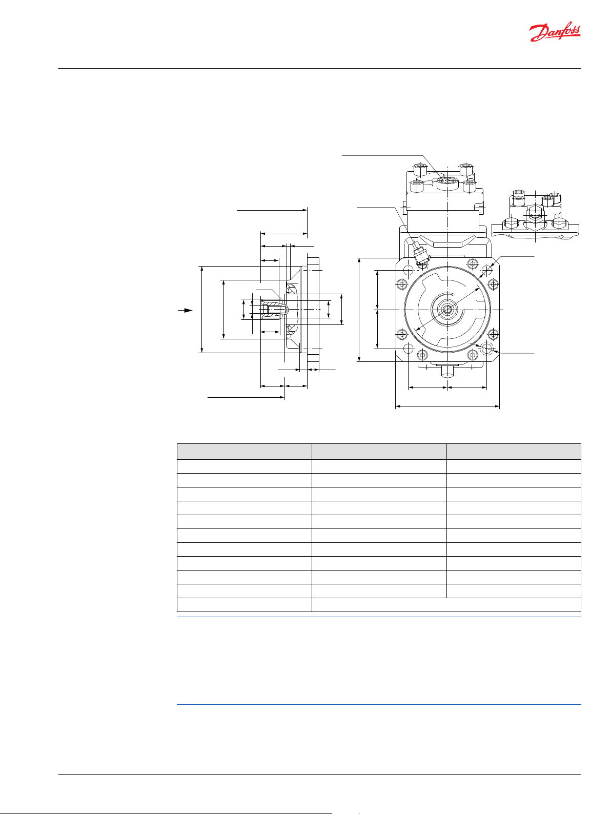
Ø125.0 -
0.063
[4.921
- 0.002
]
Ø44.45
[1.75]
ØG
ØA
Ø85.0
[3.35]
ØD
H
F
E
B
C
17.0
[0.67]
32.5
[1.28]
9.0
[0.35]
6.0
[0.24]
P001 810E
56.57
[2.23]
56.57
[2.23]
56.57
[2.23]
56.57
[2.23]
150.0 ± 1.6
[5.91 ± 0.06]
150.0 ± 1.6
[5.91 ± 0.06]
Ø110.0
[4.33]
R1.6
[0.06]
Mounting flange surface
flange 125 B4 HL
per ISO 3019/2
Coupling may not protrude
beyond this surface
Ø14.0 ± 0.2
[0.55 ± 0.01]
Speed pick-up
Ø19.5 [0.77]
other side max.
screw head space
Control pressure port “X1(M3)”
Servo pressure min. angle
0.5625-18UNF-2B
[9/
16
-18UNF-2B]
X
Z
Series 51with
HZB1-control
Z
Series 51-1with
N1NN-control
Z
Technical Information
Series 51 and 51-1 Bent Axis Variable Displ. Motors
General dimensions – frame size 060
Shaft options – 51D060-1 and 51D060
Shaft spline data - mm [in]
Shaft option D1 D2
Number of teeth 14 16
Spline W30x2x30x14x9g, side fit DIN 5480 W35x2x30x16x9g side fit DIN 5480
Pitch Ø 28.0 [1.102] 32.0 [1.260]
Ø A 29.6 [1.17] 34.6 [1.36]
B 27.0 [1.06] 32.0 [1.260]
C 35.0±0.5 [1.38] 40.0±0.5 [1.58]
Ø D 25.0 [0.98] 30.0 [1.18]
E 37.5±1.1 [1.48] 42.5±1.1 [1.67]
F 67.5±0.6 [2.66] 72.5±0.6 [2.85]
H 25.0 [0.98] 25.0 [0.98]
Ø G M10x1.5 allowed torque in thread max. 67 N•m [593 lbf•in]
Flow into port A results in CW rotation of output shaft.
Flow into port B results in CCW rotation of output shaft.
Shaft rotation is determined by viewing from shaft end. Ports with O-ring seal and inch threads shall be in
accordance with ISO 11926/1.
©
Danfoss | October 2017 520L0440 | BC00000018en-US0401 | 69
Splite flange boss A and B per ISO 6162 is identical with high pressure series SAEJ518 code 62 (6000 psi).
Contact your Danfoss representative for specific installation drawings.
Page 70

70
[2.76]
70
[2.76]
A
B
M4
50.0
[1.97]
40.0
[1.57]
130.0
[5.13]
174.3 max.
[6.86 max.]
39.0
[1.54]
39.0
[1.54]
208.5
[8.21]
99.4
[3.91]
50.8
[2.00]
23.8
[0.94]
L1
P001 792E
47.0
[1.85]
50.8
[2.00]
73.0
[2.87]
73.0
[2.87]
47.0
[1.85]
A
B
M4
23.8
[0.94]
49.0
[1.94]
158.0
[6.21]
L1
19°
Split flange boss “A”
DN 19 typ II 40 MPa series
per ISO 6162 [SAE 0.75]
4 thread: 0.375-16UNC-2B
[3/8 -16UNC-2B]
19 [0.75] min.
full thread depth
Split flange boss “B”
DN 19 typ II 40 MPa series
per ISO 6162 [SAE 0.75]
4 thread: 0.375-16UNC-2B
[3/8 -16UNC-2B]
19 [0.75] min.
full thread depth
Gauge port “M1”+”M2”
System pressure “A”+”B”
0.5625-18UNF-2B
[9/
16
-18UNF-2B]
W
Y
Gauge port “M4”
System pressure max. angle
0.5625-18UNF-2B
[9/
16
-18UNF-2B]
W
Y
X
Gauge port “M1”
System pressure “A”
0.875-14UNF-2B
[7/8 -14UNF-2B]
Gauge port “M2”
System pressure “B”
0.875-14UNF-2B
[7/8 -14UNF-2B]
Loop flushing
shuttle valve
Charge pressure
relief valve
min. angle stop
adjustment
Split flange boss “A”+”B”
DN 19 typ II 40 MPa series
per ISO 6162 [SAE 0.75]
4 thread: 0.375-16UNC-2B
[3/8 -16UNC-2B]
19 [0.75] min.
full thread depth
Case drain “L1”
1.0625-12UN-2B
[1 1/
16
-12UN-2B]
Alternate position
Case drain “L2”
1.0625-12UN-2B
[1 1/
16
-12UN-2B]
W
Y
Gauge port “M4”
System pressure max. angle
0.5625-18UNF-2B
[9/
16
-18UNF-2B]
W
Y
X
Speed pick-up
Technical Information
Series 51 and 51-1 Bent Axis Variable Displ. Motors
General dimensions – frame size 060
Cartridge flange
51C060-1 two-position control, N1NN (Side port on top, Axial port below)
70 | © Danfoss | October 2017 520L0440 | BC00000018en-US0401
Page 71

N
L2
A
L1
M3
M1
M5
45.0
[1.77]
45.0
[1.77]
50.80
[2.00]
70.0
[2.76 ]
70.0
[2.76 ]
23.80
[0.94]
Split flange boss “A”
DN 19 typ II 40 MPa series
per ISO 6162 [SAE 0.75]
4 thread: 0.375-16UNC-2B
[3/8 -16UNC-2B]
19 [0.75] min.
full thread depth
Split flange boss “B”
DN 19 typ II 40 MPa series
per ISO 6162 [SAE 0.75]
4 thread: 0.375-16UNC-2B
[3/8 -16UNC-2B]
19 [0.75] min.
full thread depth
Gauge port “M1”+”M2”
System pressure “A”+”B”
0.5625-18UNF-2B
[9/
16
-18UNF-2B]
179.0
[7.03]
P001 967E
56.0
[2.22]
Gauge port “M1”
System pressure “A”
0.5625-18UNF-2B
[9/
16
-18UNF-2B]
Gauge port “M2”
System pressure “B”
0.5625-18UNF-2B
[9/
16
-18UNF-2B]
66.0
[2.60]
66.0
[2.60]
50.0
[1.97]
Control Start
Adjustment
Gauge port “M3”
Servo pressure min. angle
0.5625-18UNF-2B
[9/
16
-18UNF-2B]
Gauge port “M5”
Servo pressure supply
0.5625-18UNF-2B
[9/
16
-18UNF-2B]
Control mounting
surface
209.0
[8.24]
39.0
[1.54]
39.0
[1.54]
172.0
[6.77]
96.0
[3.77]
41.0
[1.60]
132.0
[5.21]
19°
Case drain port “L1”
1.0625-12UN-2B
[1 1/
16
-12UN-2B]
50.80
[2.00]
23.90
[0.94]
Split flange boss “A”+”B”
DN 19 typ II 40 MPa series
per ISO 6162 [SAE 0.75]
4 thread: 0.375-16UNC-2B
[3/8 -16UNC-2B]
19 [0.75] min.
full thread depth
Gauge port “M7”
Control pressure
0.5625-18UNF-2B
[9/
16
-18UNF-2B]
99.0
[3.89]
min. angle stop
adjustment
Charge pressure
relief valve
Alternate position
Case drain port “L2”
1.0625-12UN-2B
[1 1/
16
-12UN-2B]
Loop Flushing
shuttle valve
L2
N
L1
M3
B
A
M5
M4
Y
Y
X
U
Y
Y
X
Shaft centerline
Control pressure port “X1”
0.5625-18UNF-2B
[9/
16
-18UNF-2B]
U
X1
M7
49.0
[1.93]
Supply pressure
Shuttle valve
0.5625-18UNF-2B
[9/
16
-18UNF-2B]
Gauge port “M4”
Servo pressure max. angle
0.5625-18UNF-2B
[9/
16
-18UNF-2B]
W
W
M4
Supply pressure
Shuttle valve
0.5625-18UNF-2B
[9/
16
-18UNF-2B]
Gauge port “M4”
Servo pressure max. angle
0.5625-18UNF-2B
[9/
16
-18UNF-2B]
W
W
M4
Technical Information
Series 51 and 51-1 Bent Axis Variable Displ. Motors
General dimensions – frame size 060
51C060 proportional and two-position control, HZB1 (Side port on top, Axial port below)
©
Danfoss | October 2017 520L0440 | BC00000018en-US0401 | 71
Page 72

P001 811E
100.0
[3.94]
100.0
[3.94]
Clearance
min. Ø242.0
[9.53]
Ø18.0 ± 0.3
[0.71 ± 0.01]
236.9 max.
[9.33] max.
ØG
ØA
Ø90.0
[3.54]
Ø106.0
[4.17]
Ø134.0
[5.28]
79.5
[3.13]
74.5
[2.93]
H
56.0
[2.20]
B
E
F
C
12.6
[0.50]
91.8
[3.61]
20.0
[0.79]
20.0
[0.79]
ØD
Ø160.0
- 0.025
[6.299
- 0.001
]
R1.6
[0.06]
M3
Ø44.45
[1.75]
Z
X
Mounting flange surface
cartridge flange
Alternate position
Case drain “L1”
1.0625-12UN-2B
[1 1/
16
-12UN-2B]
Coupling may not protrude
beyond this surface
Case drain “L2”
1.0625-12UN-2B
[1 1/
16
-12UN-2B]
O-ring 3.00x150.00 FPM
[0.12x5.90]
Ø30.0 [1.18]
other side max
screen head space
Control pressure port “X1(M3)”
Servo pressure min. angle
0.5625-18UNF-2B
[9/
16
-18UNF-2B]
Series 51 with
HZB1-control
Z
Series 51-1 with
N1NN-control
Z
Technical Information
Series 51 and 51-1 Bent Axis Variable Displ. Motors
General dimensions – frame size 060
Shaft options – 51C060-1 and 51C060
Shaft spline data - mm [in]
Shaft option D1 D2
Number of teeth 14 16
Spline W30x2x30x14x9g, side fit DIN 5480 W35x2x30x16x9g side fit DIN 5480
Pitch Ø 28.0 [1.102] 32.0 [1.26]
Ø A 29.6 [1.17] 34.6 [1.36]
B 27.0 [1.06] 32.0 [1.26]
C 35.0±0.5 [1.38] 40.0±0.5 [1.58]
Ø D 25.0 [0.98] 30.0 [1.18]
E 36.8±1.4 [1.45] 41.8±1.4 [1.65]
F 127.2±0.6 [5.0] 132.2±0.6 [5.21]
H 25.0 [0.98] 25.0 [0.98]
Ø G M10x1.5 allowed torque in thread max. 67 N•m [593 lbf•in]
Flow into port A results in CW rotation of output shaft.
Flow into port B results in CCW rotation of output shaft.
Shaft rotation is determined by viewing from shaft end. Ports with O-ring seal and inch threads shall be in
accordance with ISO 11926/1.
Splite flange boss A and B per ISO 6162 is identical with high pressure series SAEJ518 code 62 (6000 psi).
Contact your Danfoss representative for specific installation drawings.
72 | © Danfoss | October 2017 520L0440 | BC00000018en-US0401
Page 73

P001 793E
57.12
[2.25]
50.0
[1.97]
79.0
[3.11]
79.0
[3.11]
50.0
[1.97]
A
B
M4
27.76
[1.09]
53.0
[2.10]
116.0
[4.58]
261.0
[10.28]
134.0
[5.26]
93.7
[3.69]
94.0
[3.69]
45.0
[1.76]
19°
235.0
[9.27]
278.2 max.
[10.95 max.]
85.5
[3.37]
80.0
[3.15]
218.9
[8.62]
106.7
[4.20]
27.76
[1.09]
57.12
[2.25]
76.0
[2.99]
76.0
[2.99]
M4
A
B
Y
X
W
Y
Gauge port “M4”
System pressure max. angle
0.5625-18UNF-2B
[9/
16
-18UNF-2B]
W
Loop flushing
shuttle valve
Charge pressure
relief valve
min. angle stop
adjustment
Split flange boss “A”+”B”
DN 25 typ II 40 MPa series
per ISO 6162 [SAE 1.00]
4 thread: 0.4375-14UNC-2B
[7/
16
-14UNC-2B]
27 [1.06] min.
full thread depth
Case drain “L1”
1.0625-12UN-2B
[1 1/
16
-12UN-2B]
Alternate position
Case drain “L2”
1.0625-12UN-2B
[1 1/
16
-12UN-2B]
Gauge port “M1”
System pressure “A”
1.0625-12UNF-2B
[1 1/
16
-12UNF-2B]
Gauge port “M2”
System pressure “B”
1.0625-12UNF-2B
[1 1/
16
-12UNF-2B]
Y
X
W
Y
Gauge port “M4”
System pressure max. angle
0.5625-18UNF-2B
[9/
16
-18UNF-2B]
W
Gauge ports “M1”+”M2”
System pressure “A”+”B”
0.5625-18UNF-2B
[9/
16
-18UNF-2B]
Split flange boss “A”
DN 25 typ II 40 MPa series
per ISO 6162 [SAE 1.00]
4 thread: 0.4375-14UNC-2B
[7/
16
-14UNC-2B]
27 [1.06] min.
full thread depth
Split flange boss “B”
DN 25 typ II 40 MPa series
per ISO 6162 [SAE 1.00]
4 thread: 0.4375-14UNC-2B
[7/
16
-14UNC-2B]
27 [1.06] min.
full thread depth
Technical Information
Series 51 and 51-1 Bent Axis Variable Displ. Motors
General dimensions – frame size 080
SAE flange design per ISO 3019/1
51V080-1 Two Position Control, N1NN (Side port on top, Axial port below)
©
Danfoss | October 2017 520L0440 | BC00000018en-US0401 | 73
Page 74

P001 794E
51.0
[2.01]
51.0
[2.01]
57.15
[2.25]
81.0
[2.01]
81.0
[2.01]
M3
M5
B
A
M4
27.76
[1.09]
Split flange boss “A”
DN 25 typ II 40 MPa series
per ISO 6162 [SAE 1.00]
4 thread: 0.4375-14UNC-2B
[7/
16
-14UNC-2B]
27 [1.06] min.
full thread depth
Split flange boss “B”
DN 25 typ II 40 MPa series
per ISO 6162 [SAE 1.00]
4 thread: 0.4375-14UNC-2B
[7/
16
-14UNC-2B]
27 [1.06] min.
full thread depth
Gauge port “M1”+”M2”
System pressure “A”+”B”
0.5625-18UNF-2B
[9/
16
-18UNF-2B]
282.0
[11.09]
61.0
[2.39]
116.0
[4.58]
134.0
[5.26]
Gauge port “M2”
System pressure “B”
0.5625-18UNF-2B
[9/
16
-18UNF-2B]
Gauge port “M1”
System pressure “A”
0.5625-18UNF-2B
[9/
16
-18UNF-2B]
74.0
[2.91]
74.0
[2.91]
93.7
[3.69]
94.0
[3.69]
Control start
adjustment
Gauge port “M3”
Servo pressure min. angle
0.5625-18UNF-2B
[9/
16
-18UNF-2B]
Gauge port “M5”
Servo pressure supply
0.5625-18UNF-2B
[9/
16
-18UNF-2B]
Control Mounting
Surface
Loop flushing
shuttle valve
318.0
[12.52]
85.5
[3.37]
80.0
[3.15]
183.0
[7.19]
102.0
[4.00]
M1
M5
M3
A
45.0
[1.76]
235.0
[9.27]
Alternate position
Case drain “L2”
1.0625-12UN-2B
[1 1/
16
-12UN-2B]
19°
Case drain “L1”
1.0625-12UN-2B
[1 1/
16
-12UN-2B]
Split flange boss “A”+”B”
DN 25 typ II 40 MPa series
per ISO 6162 [SAE 1.00]
4 thread: 0.4375-14UNC-2B
[7/
16
-14UNC-2B]
27 [1.06] min.
full thread depth
Gauge port “M7”
Control pressure
0.5625-18UNF-2B
[9/
16
-18UNF-2B]
107.0
[4.20]
min. angle stop
adjustment
Charge pressure
relief valve
Y
Y
X
U
Y
Y
X
Shaft centerline
Control pressure port “X1”
0.5625-18UNF-2B
[9/
16
-18UNF-2B]
U
X1
M7
49.0
[1.93]
Supply pressure
Shuttle valve
0.5625-18UNF-2B
[9/
16
-18UNF-2B]
Gauge port “M4”
Servo pressure max. angle
0.5625-18UNF-2B
[9/
16
-18UNF-2B]
W
W
M4
Supply pressure
Shuttle valve
0.5625-18UNF-2B
[9/
16
-18UNF-2B]
Gauge port “M4”
Servo pressure max. angle
0.5625-18UNF-2B
[9/
16
-18UNF-2B]
W
W
M4
27.76
[1.09]
57.15
[2.25]
Technical Information
Series 51 and 51-1 Bent Axis Variable Displ. Motors
General dimensions – frame size 080
51V080 Proportional and Two-Position Control, HZB1 (Side port on top, Axial port below)
74 | © Danfoss | October 2017 520L0440 | BC00000018en-US0401
Page 75

Ø126.975 ± 0.025
[4.999 ± 0.001]
Ø80.0
[3.15]
Ø44.0
[1.75]
ØG
ØA
ØD
H
F
E
B
57.25
[2.25]
57.25
[2.25]
57.25
[2.25]
150.0 ± 1.6
[5.91 ± 0.06]
150.0 ± 1.6
[5.91 ± 0.06]
57.25
[2.25]
P001 812E
C
12.0
[0.49]
20.0
[0.79]
R3.0
[0.12]
Coupling may not protrude
beyond this surface
Mounting flange surface
flange 127-4 (SAE "C")
per ISO 3019/1
O-ring 3.00x116.00 FPM
[0.12x4.57]
Ø19.5 [0.77]
other side max.
screw head space
4x Ø14.5 ± 0.2
[0.57 ± 0.01]
Speed pick-up
Control pressure port “X1(M3)”
Servo pressure min. angle
0.5625-18UNF-2B
[9/
16
-18UNF-2B]
X
Z
Series 51 with
HZB1-control
Z
Series 51-1 with
N1NN-control
Z
Technical Information
Series 51 and 51-1 Bent Axis Variable Displ. Motors
General dimensions – frame size 080
Shaft Options – 51V080-1 and 51V080
Shaft spline data - mm [in]
Shaft option S1 C7
Number of teeth 14 23
Pitch 12/24 16/32
Pitch Ø 29.633 [1.167] 36.513 [1.438]
Ø A 31.15 [1.23] 37.61 [1.481]
Ø D 25.8 [1.02] 32.0 [1.26]
Pressure angle 30°
B 37.5 [1.476]
C 47.5±0.5 [1.87]
E 49.5±1.1 [1.95]
F 55.5±0.7 [2.19]
H 28.0 [1.1]
Spline ANSI B92.1-1970, class 5, flat root side fit
Ø G 0.4375-14UNC-2B [7/16-14UNC-2B]; allowed torque in thread max. 91 N•m
[805 lbf•in]
Flow into port A results in CW rotation of output shaft.
Flow into port B results in CCW rotation of output shaft.
Shaft rotation is determined by viewing from shaft end. Ports with O-ring seal and inch threads shall be in
accordance with ISO 11926/1.
Splite flange boss A and B per ISO 6162 is identical with high pressure series SAEJ518 code 62 (6000 psi).
Contact your Danfoss representative for specific installation drawings.
©
Danfoss | October 2017 520L0440 | BC00000018en-US0401 | 75
Page 76

P001 795E
57.12
[2.25]
50.0
[1.97]
79.0
[3.11]
79.0
[3.11]
50.0
[1.97]
A
B
M4
27.76
[1.09]
53.0
[2.10]
112.0
[4.40]
237.0
[9.33]
96.0
[3.80]
76.0
[2.99]
76.0
[2.99]
A
B
M4
109.8
[4.32]
70.0
[2.75]
45.0
[1.76]
19°
211.0
[8.33]
252.7 max.
[9.95 max.]
87.5
[3.44]
76.5
[3.01]
218.9
[8.62]
106.7
[4.20]
27.76
[1.09]
57.12
[2.25]
Loop flushing
shuttle valve
Charge pressure
relief valve
min. angle stop
adjustment
Split flange boss “A”+”B”
DN 25 typ II 40 MPa series
per ISO 6162 [SAE 1.00]
4 thread: 0.4375-14UNC-2B
[7/
16
-14UNC-2B]
27 [1.06] min.
full thread depth
Case drain “L1”
1.0625-12UN-2B
[1 1/
16
-12UN-2B]
Alternate position
Case drain “L2”
1.0625-12UN-2B
[1 1/
16
-12UN-2B]
Y
X
W
Y
Gauge port “M4”
System pressure max. angle
0.5625-18UNF-2B
[9/
16
-18UNF-2B]
W
Gauge port “M1”
System pressure “A”
1.0625-12UNF-2B
[1 1/
16
-12UNF-2B]
Gauge port “M2”
System pressure “B”
1.0625-12UNF-2B
[1 1/
16
-12UNF-2B]
Y
X
W
Y
Gauge port “M4”
System pressure max. angle
0.5625-18UNF-2B
[9/
16
-18UNF-2B]
W
Gauge ports “M1”+”M2”
System pressure “A”+”B”
0.5625-18UNF-2B
[9/
16
-18UNF-2B]
Split flange boss “A”
DN 25 typ II 40 MPa series
per ISO 6162 [SAE 1.00]
4 thread: 0.4375-14UNC-2B
[7/
16
-14UNC-2B]
27 [1.06] min.
full thread depth
Split flange boss “B”
DN 25 typ II 40 MPa series
per ISO 6162 [SAE 1.00]
4 thread: 0.4375-14UNC-2B
[7/
16
-14UNC-2B]
27 [1.06] min.
full thread depth
Technical Information
Series 51 and 51-1 Bent Axis Variable Displ. Motors
General dimensions – frame size 080
DIN flange design per ISO 3019/2
51D080-1 two position control, N1NN (Side port on top, Axial port below)
76 | © Danfoss | October 2017 520L0440 | BC00000018en-US0401
Page 77

P001 796E
109.8
[4.32]
66.65
[2.62]
Control start
adjustment
Gauge port “M3”
Servo pressure min. angle
0.5625-18UNF-2B
[9/
16
-18UNF-2B]
Gauge port “M5”
Servo pressure supply
0.5625-18UNF-2B
[9/
16
-18UNF-2B]
Control mounting
surface
Loop flushing
shuttle valve
294.0
[11.58]
87.5
[3.44]
76.5
[3.01]
183.0
[7.19]
102.0
[4.00]
M1
M5
M3
A
45.0
[1.76]
211.0
[8.33]
Alternate position
Case drain “L2”
1.0625-12UN-2B
[1 1/
16
-12UN-2B]
19°
Case drain “L1”
1.0625-12UN-2B
[1 1/
16
-12UN-2B]
min. angle stop
adjustment
Gauge port “M7”
Control pressure
0.5625-18UNF-2B
[9/
16
-18UNF-2B]
107.0
[4.20]
27.76
[1.09]
57.15
[2.25]
Charge pressure
relief valve
Split flange boss “A”+”B”
DN 25 typ II 40 MPa series
per ISO 6162 [SAE 1.00]
4 thread: 0.4375-14UNC-2B
[7/
16
-14UNC-2B]
27 [1.06] min.
full thread depth
Gauge port “M2”
System pressure “B”
0.5625-18UNF-2B
[9/
16
-18UNF-2B]
Gauge port “M1”
System pressure “A”
0.5625-18UNF-2B
[9/
16
-18UNF-2B]
74.0
[2.91]
74.0
[2.91]
51
[2.01]
57.15
[2.25]
81.0
[3.19]
81.0
[3.19]
51
[2.01]
M3
B
A
M4
M5
27.76
[1.09]
Split flange boss “A”
DN 25 typ II 40 MPa series
per ISO 6162 [SAE 1.00]
4 thread: 0.4375-14UNC-2B
[7/
16
-14UNC-2B]
27 [1.06] min.
full thread depth
Split flange boss “B”
DN 25 typ II 40 MPa series
per ISO 6162 [SAE 1.00]
4 thread: 0.4375-14UNC-2B
[7/
16
-14UNC-2B]
27 [1.06] min.
full thread depth
Gauge port “M1”+”M2”
System pressure “A”+”B”
0.5625-18UNF-2B
[9/
16
-18UNF-2B]
258.0
[10.15]
61.0
[2.39]
112.0
[4.40]
96.0
[3.80]
Y
Y
X
U
Y
X
W
Shaft centerline
Control pressure port “X1”
0.5625-18UNF-2B
[9/
16
-18UNF-2B]
U
X1
M7
49.0
[1.93]
Supply pressure
Shuttle valve
0.5625-18UNF-2B
[9/
16
-18UNF-2B]
Gauge port “M4”
Servo pressure max. angle
0.5625-18UNF-2B
[9/
16
-18UNF-2B]
W
M4
Supply pressure
Shuttle valve
0.5625-18UNF-2B
[9/
16
-18UNF-2B]
Gauge port “M4”
Servo pressure max. angle
0.5625-18UNF-2B
[9/
16
-18UNF-2B]
W
W
M4
Technical Information
Series 51 and 51-1 Bent Axis Variable Displ. Motors
General dimensions – frame size 080
51D080 Proportional and two position control, HZB1 (Side port on top, Axial port below)
©
Danfoss | October 2017 520L0440 | BC00000018en-US0401 | 77
Page 78

P001 813E
∅45.0
[1.75]
ØG
ØA
ØD
H
F
E
B
C
Ø140.0
- 0.063
[5.512
- 0.002
]
19.0
[0.75]
32.1
[1.26]
10.0
[0.39]
R1.6
[0.06]
Ø110.0
[4.33]
63.6
[2.5]
63.6
[2.5]
168.0 ± 1.6
[6.61 ± 0.06]
63.6
[2.5]
63.6
[2.5]
168.0 ± 1.6
[6.61 ± 0.06]
Mounting flange surface
flange 140 B4 HL
per ISO 3019/2
Coupling may not protrude
beyond this surface
4x Ø14.0 ± 0.2
[0.55 ± 0.01]
Speed pick-up
Ø19.5 [0.77]
other side max.
screw head space
Control pressure port “X1(M3)”
Servo pressure min. angle
0.5625-18UNF-2B
[9/
16
-18UNF-2B]
X
Z
Series 51-1 with
N1NN-control
Z
Series 51 with
HZB1-control
Z
Technical Information
Series 51 and 51-1 Bent Axis Variable Displ. Motors
General dimensions – frame size 080
Shaft Options – 51D080-1 and 51D080
Shaft spline data - mm [in]
Shaft option D2 D3
Number of teeth 16 18
Spline W35x2x30x16x9g side fit DIN 5480 W40x2x30x18x9g side fit DIN 5480
Pitch Ø 32.0 [1.260] 36.0 [1.417]
Ø A 34.6 [1.36] 39.6 [1.56]
B 32.0 [1.26] 37.0 [1.46]
C 40.0±0.5 [1.58] 45.0±0.5 [1.77]
Ø D 30.0 [1.18] 35.0 [1.38]
E 42.5±1.1 [1.67] 47.3±1.1 [1.86]
F 72.5±0.6 [2.85] 85.3±0.6 [3.36]
H 25.0 [0.98] 25.0 [0.98]
Ø G M10x1.5 allowed torque in thread max. 67 N•m [593 lbf•in]
Flow into port A results in CW rotation of output shaft.
Flow into port B results in CCW rotation of output shaft.
Shaft rotation is determined by viewing from shaft end. Ports with O-ring seal and inch threads shall be in
accordance with ISO 11926/1.
Splite flange boss A and B per ISO 6162 is identical with high pressure series SAEJ518 code 62 (6000 psi).
Contact your Danfoss representative for specific installation drawings.
78 | © Danfoss | October 2017 520L0440 | BC00000018en-US0401
Page 79

P001 797E
76.0
[2.99]
76.0
[2.99]
A
B
M4
L1
48.0
[1.89]
45.0
[1.77]
133.0
[5.24]
174.4 max.
[6.87 max.]
45.0
[1.77]
45.0
[1.77]
218.9
[8.62]
106.7
[4.20]
27.76
[1.09]
57.12
[2.25]
57.12
[2.25]
50.0
[1.97]
79.0
[3.11]
79.0
[3.11]
50.0
[1.97]
A
B
M4
27.76
[1.09]
53.0
[2.10]
159.0
[6.25]
L1
19°
Y
X
W
Y
Gauge port “M4”
System pressure max. angle
0.5625-18UNF-2B
[9/
16
-18UNF-2B]
W
Y
X
W
Y
Gauge port “M4”
System pressure max. angle
0.5625-18UNF-2B
[9/
16
-18UNF-2B]
W
Loop flushing
shuttle valve
Charge pressure
relief valve
min. angle stop
adjustment
Split flange boss “A”+”B”
DN 25 typ II 40 MPa series
per ISO 6162 [SAE 1.00]
4 thread: 0.4375-14UNC-2B
[7/
16
-14UNC-2B]
27 [1.06] min.
full thread depth
Case drain “L1”
1.0625-12UN-2B
[1 1/
16
-12UN-2B]
Alternate position
Case drain “L2”
1.0625-12UN-2B
[1 1/
16
-12UN-2B]
Gauge port “M1”
System pressure “A”
1.0625-12UNF-2B
[1 1/
16
-12UNF-2B]
Gauge port “M2”
System pressure “B”
1.0625-12UNF-2B
[1 1/
16
-12UNF-2B]
Speed pick-up
Gauge ports “M1”+”M2”
System pressure “A”+”B”
0.5625-18UNF-2B
[9/
16
-18UNF-2B]
Split flange boss “A”
DN 25 typ II 40 MPa series
per ISO 6162 [SAE 1.00]
4 thread: 0.4375-14UNC-2B
[7/
16
-14UNC-2B]
27 [1.06] min.
full thread depth
Split flange boss “B”
DN 25 typ II 40 MPa series
per ISO 6162 [SAE 1.00]
4 thread: 0.4375-14UNC-2B
[7/
16
-14UNC-2B]
27 [1.06] min.
full thread depth
Technical Information
Series 51 and 51-1 Bent Axis Variable Displ. Motors
General dimensions – frame size 080
Cartridge flange
51C080-1 two-position control, N1NN (Side port on top, Axial port below)
©
Danfoss | October 2017 520L0440 | BC00000018en-US0401 | 79
Page 80

P001 798E
57.15
[2.25]
51.0
[2.01]
51.0
[2.01]
81.0
[3.19]
81.0
[3.19]
M4
M5
B
A
M3
27.76
[1.09]
Split flange boss “A”
DN 25 typ II 40 MPa series
per ISO 6162 [SAE 1.00]
4 thread: 0.4375-14UNC-2B
[7/
16
-14UNC-2B]
27 [1.06] min.
full thread depth
Split flange boss “B”
DN 25 typ II 40 MPa series
per ISO 6162 [SAE 1.00]
4 thread: 0.4375-14UNC-2B
[7/
16
-14UNC-2B]
27 [1.06] min.
full thread depth
Gauge port “M1”+”M2”
System pressure “A”+”B”
0.5625-18UNF-2B
[9/
16
-18UNF-2B]
179.0
[7.07]
61.0
[2.39]
L1
19°
48.0
[1.98]
Control start
adjustment
Gauge port “M3”
Servo pressure min. angle
0.5625-18UNF-2B
[9/
16
-18UNF-2B]
Gauge port “M5”
Servo pressure supply
0.5625-18UNF-2B
[9/
16
-18UNF-2B]
Control mounting
surface
Speed pick-up
215.0
[8.45]
183.0
[7.19]
102.0
[4.00]
M1
M5
M3
A
45.0
[1.77]
133.0
[5.24]
Alternate position
Case drain “L2”
1.0625-12UN-2B
[1 1/
16
-12UN-2B]
Case drain “L1”
1.0625-12UN-2B
[1 1/
16
-12UN-2B]
Gauge port “M7”
Control pressure
0.5625-18UNF-2B
[9/
16
-18UNF-2B]
107.0
[4.20]
Charge pressure
relief valve
45.0
[1.77]
45.0
[1.77]
L1
57.15
[2.25]
27.76
[1.09]
Loop flushing
shuttle valve
Split flange boss “A”+”B”
DN 25 typ II 40 MPa series
per ISO 6162 [SAE 1.00]
4 thread: 0.4375-14UNC-2B
[7/
16
-14UNC-2B]
27 [1.06] min.
full thread depth
min. angle stop
adjustment
Gauge port “M2”
System pressure “B”
0.5625-18UNF-2B
[9/
16
-18UNF-2B]
Gauge port “M1”
System pressure “A”
0.5625-18UNF-2B
[9/
16
-18UNF-2B]
74.0
[2.91]
74.0
[2.91]
Shaft centerline
Control pressure port “X1”
0.5625-18UNF-2B
[9/
16
-18UNF-2B]
U
X1
M7
49.0
[1.93]
Supply pressure
Shuttle valve
0.5625-18UNF-2B
[9/
16
-18UNF-2B]
Gauge port “M4”
Servo pressure max. angle
0.5625-18UNF-2B
[9/
16
-18UNF-2B]
W
W
M4
Supply pressure
Shuttle valve
0.5625-18UNF-2B
[9/
16
-18UNF-2B]
Gauge port “M4”
Servo pressure max. angle
0.5625-18UNF-2B
[9/
16
-18UNF-2B]
W
W
M4
Y
X
Y
U
Y
Y
X
Technical Information
Series 51 and 51-1 Bent Axis Variable Displ. Motors
General dimensions – frame size 080
51C080 proportional and two-position control, HZB1 (Side port on top, Axial port below)
80 | © Danfoss | October 2017 520L0440 | BC00000018en-US0401
Page 81
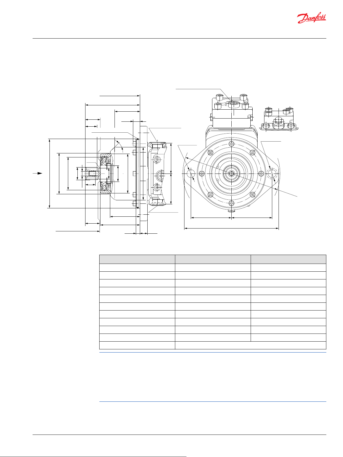
P001 814E
112.0
[4.41]
112.0
[4.41]
Ø22.0 ± 0.3
[0.87 ± 0.01]
261.9 max.
[10.31 max.]
Ø30.0 [1.18]
other side max.
screw head space
ØG
ØA
Ø90.0
[3.54]
Ø112.0
[4.41]
84.5
[3.33]
84.5
[3.35]
28.0
[1.10]
B
45°
E
70.7
[2.78]
F
C
Coupling may not protrude
beyond this surface
11.2
[0.44]
81.5
[3.21]
110.8 max
[4.36 max]
20.0
[0.79]
Ø190.0
- 0.029
[7.48
- 0.001
]
R1.6
[0.06]
M3
ØD
Ø44.45
[1.75]
Ø108.0
[4.25]
19.2
[0.76]
Clearance
min. Ø267.5
[10.53]
O-ring 3.00x179.00 FPM
[0.12x7.04]
Mounting flange surface
cartridge flange
Ø143.0
[5.71]
Z
X
Alternate position
Case drain “L2”
1.0625-12UN-2B
[1 1/
16
-12UN-2B]
Case drain “L1”
1.0625-12UN-2B
[1 1/
16
-12UN-2B]
Control pressure port “X1(M3)”
Servo pressure min. angle
0.5625-18UNF-2B
[9/
16
-18UNF-2B]
Series 51-1 with
N1NN-control
Z
Series 51with
HZB1-control
Z
Technical Information
Series 51 and 51-1 Bent Axis Variable Displ. Motors
General dimensions – frame size 080
Shaft options – 51C080-1 and 51C080
Shaft spline data - mm [in]
Shaft option D2 D3
Number of teeth 16 18
Spline W35x2x30x16x9g side fit DIN 5480 W40x2x30x18x9g side fit DIN 5480
Pitch Ø 32.0 [1.260] 36.0 [1.417]
Ø A 34.6 [1.36] 39.6 [1.56]
B 32.0 [1.26] 37.0 [1.46]
C 40.0±0.5 [1.58] 45.0±0.5 [1.77]
Ø D 30.0 [1.18] 35.0 [1.38]
E 41.55±1.4 [1.64] 46.55±1.4 [1.83]
F 150.4±0.6 [5.92] 155.4±0.6 [6.12]
H 25.0 [0.98] 25.0 [0.98]
Ø G M10x1.5 allowed torque in thread max. 67 N•m [593 lbf•in]
Flow into port A results in CW rotation of output shaft.
Flow into port B results in CCW rotation of output shaft.
Shaft rotation is determined by viewing from shaft end. Ports with O-ring seal and inch threads shall be in
accordance with ISO 11926/1.
Splite flange boss A and B per ISO 6162 is identical with high pressure series SAEJ518 code 62 (6000 psi).
Contact your Danfoss representative for specific installation drawings.
©
Danfoss | October 2017 520L0440 | BC00000018en-US0401 | 81
Page 82

P001 799E
57.12
[2.25]
50.0
[1.97]
80.0
[3.15]
80.0
[3.15]
50.0
[1.97]
A
B
M4
27.76
[1.09]
58.0
[2.27]
121.0
[4.74]
281.0
[11.05]
134.0
[5.27]
77.0
[3.03]
77.0
[3.03]
A
B
M4
101.0
[3.98]
101.0
[3.98]
48.0
[1.91]
19°
254.0
[10.01]
301.2 max.
[11.82 max.]
143.0
[5.63]
87.0
[3.43]
90.0
[3.54]
232.6
[9.16]
115.0
[4.53]
27.76
[1.09]
57.12
[2.25]
Gauge ports “M1”+”M2”
System pressure “A”+”B”
0.5625-18UNF-2B
[9/
16
-18UNF-2B]
Split flange boss “A”
DN 25 typ II 40 MPa series
per ISO 6162 [SAE 1.00]
4 thread: 0.4375-14UNC-2B
[7/
16
-14UNC-2B]
27 [1.06] min.
full thread depth
Split flange boss “B”
DN 25 typ II 40 MPa series
per ISO 6162 [SAE 1.00]
4 thread: 0.4375-14UNC-2B
[7/
16
-14UNC-2B]
27 [1.06] min.
full thread depth
Y
X
W
Y
Gauge port “M4”
System pressure max. angle
0.5625-18UNF-2B
[9/
16
-18UNF-2B]
W
Loop flushing
shuttle valve
Charge pressure
relief valve
min. angle stop
adjustment
Split flange boss “A”+”B”
DN 25 typ II 40 MPa series
per ISO 6162 [SAE 1.00]
4 thread: 0.4375-14UNC-2B
[7/
16
-14UNC-2B]
27 [1.06] min.
full thread depth
Case drain “L1”
1.0625-12UN-2B
[1 1/
16
-12UN-2B]
Alternate position
Case drain “L2”
1.0625-12UN-2B
[1 1/
16
-12UN-2B]
Gauge port “M1”
System pressure “A”
1.0625-12UNF-2B
[1 1/
16
-12UNF-2B]
Gauge port “M2”
System pressure “B”
1.0625-12UNF-2B
[1 1/
16
-12UNF-2B]
Y
X
Y
W
Gauge port “M4”
System pressure max. angle
0.5625-18UNF-2B
[9/
16
-18UNF-2B]
W
Technical Information
Series 51 and 51-1 Bent Axis Variable Displ. Motors
General dimensions – frame size 110
SAE flange design per ISO 3019/1
51V110-1 Two Position Control, N1NN (Side port on top, Axial port below)
82 | © Danfoss | October 2017 520L0440 | BC00000018en-US0401
Page 83

P001 800E
50.0
[1.97]
57.15
[2.25]
80.0
[3.15]
80.0
[3.15]
50.0
[1.97]
M3
M5
M4
A
B
27.76
[1.09]
Split flange boss “A”
DN 25 typ II 40 MPa series
per ISO 6162 [SAE 1.00]
4 thread: 0.4375-14UNC-2B
[7/
16
-14UNC-2B]
27 [1.06] min.
full thread depth
Split flange boss “B”
DN 25 typ II 40 MPa series
per ISO 6162 [SAE 1.00]
4 thread: 0.4375-14UNC-2B
[7/
16
-14UNC-2B]
27 [1.06] min.
full thread depth
Gauge port “M1”
System pressure “A”
0.5625-18UNF-2B
[9/
16
-18UNF-2B]
Gauge port “M2”
System pressure “B”
0.5625-18UNF-2B
[9/
16
-18UNF-2B]
77.0
[3.03]
77.0
[3.03]
Gauge port “M1”+”M2”
System pressure “A”+”B”
0.5625-18UNF-2B
[9/
16
-18UNF-2B]
300.0
[11.8]
64.0
[2.53]
121.0
[4.74]
134.0
[5.27]
101.0
[3.98]
101.0
[3.98]
Control start
adjustment
Gauge port “M3”
Servo pressure min. angle
0.5625-18UNF-2B
[9/
16
-18UNF-2B]
Gauge port “M5”
Servo pressure supply
0.5625-18UNF-2B
[9/
16
-18UNF-2B]
Control mounting
surface
Loop flushing
shuttle valve
Charge pressure
relief valve
337.0
[13.25]
143.0
[5.63]
90.0
[3.54]
87.0
[3.43]
185.0
[7.30]
103.0
[4.00]
49.0
[1.91]
254.0
[10.01]
Alternate position
Case drain “L2”
1.0625-12UN-2B
[1 1/
16
-12UN-2B]
19°
Case drain “L”
1.0625-12UN-2B
[1 1/
16
-12UN-2B]
Gauge port “M7”
Control pressure
0.5625-18UNF-2B
[9/
16
-18UNF-2B]
115 max.
[4.53] max.
A
M1
M5
M3
Split flange boss “A”+”B”
DN 25 typ II 40 MPa series
per ISO 6162 [SAE 1.00]
4 thread: 0.4375-14UNC-2B
[7/
16
-14UNC-2B]
27 [1.06] min.
full thread depth
min. angle stop
adjustment
Shaft centerline
Control pressure port “X1”
0.5625-18UNF-2B
[9/
16
-18UNF-2B]
U
X1
M7
49.0
[1.93]
Supply pressure
Shuttle valve
0.5625-18UNF-2B
[9/
16
-18UNF-2B]
Gauge port “M4”
Servo pressure max. angle
0.5625-18UNF-2B
[9/
16
-18UNF-2B]
W
W
M4
Supply pressure
Shuttle valve
0.5625-18UNF-2B
[9/
16
-18UNF-2B]
Gauge port “M4”
Servo pressure max. angle
0.5625-18UNF-2B
[9/
16
-18UNF-2B]
W
W
M4
Y
X
U
Y
Y
Y
X
57.15
[2.25]
27.76
[1.09]
Technical Information
Series 51 and 51-1 Bent Axis Variable Displ. Motors
General dimensions – frame size 110
51V110 Proportional and Two-Position Control, HZB1 (Side port on top, Axial port below)
©
Danfoss | October 2017 520L0440 | BC00000018en-US0401 | 83
Page 84

80.8 ± 0.2
[3.18 ± 0.01]
Ø20.5 ± 0.2
[0.81 ± 0.01]
80.8 ± 0.2
[3.18 ± 0.01]
80.8 ± 0.2
[3.18 ± 0.01]
80.8 ± 0.2
[3.18 ± 0.01]
Ø30.0 [1.18]
other side max.
screw head space
200.0 ± 1.8
[7.87 ± 0.07]
200.0 ± 1.8
[7.87 ± 0.07]
P001 815E
Ø152.375 ± 0.025
[5.999 ± 0.001]
Ø100.0
[3.94]
Ø55.0
[2.17]
ØG
ØA
ØD
Ø128.1
[5.04]
H
F
E
B
C
Coupling may not protrude
beyond this surface
12.45
[0.49]
22.0
[0.87]
R3.0
[0.12]
Mounting flange surface
flange 152-4 (SAE "D")
per ISO 3019/1
O-ring 3.00x142.00 FPM
[0.12x5.59]
Speed pick-up
Control pressure port “X1(M3)”
Servo pressure min. angle
0.5625-18UNF-2B
[9/
16
-18UNF-2B]
X
Z
Series 51 with
HZB1-control
Z
Series 51 with
HZB1-control
Z
Technical Information
Series 51 and 51-1 Bent Axis Variable Displ. Motors
General dimensions – frame size 110
Shaft Options – 51V110-1 and 51V110
Shaft spline data - mm [in]
Shaft option F1 C8
Number of teeth 13 27
Pitch 8/16 16/32
Pitch Ø 41.275 [1.625] 42.862 [1.688]
Ø A 43.64 [1.72] 43.96 [1.73]
Ø D 36.0 [1.42] 39.60 [1.56]
Pressure angle 30°
B 55.0 [2.17]
C 67.0±0.5 [2.64]
E 69.8±1.1 [2.75]
F 75.40±0.7 [2.97]
H 28.0 [1.1]
Spline ANSI B92.1-1970, class 5, flat root side fit
Ø G 0.625-11UNC-2B [5/8-11UNC-2B]; allowed torque in thread max. 200 N•m
[1770 lbf•in]
Flow into port A results in CW rotation of output shaft.
Flow into port B results in CCW rotation of output shaft.
Shaft rotation is determined by viewing from shaft end. Ports with O-ring seal and inch threads shall be in
accordance with ISO 11926/1.
Splite flange boss A and B per ISO 6162 is identical with high pressure series SAEJ518 code 62 (6000 psi).
Contact your Danfoss representative for specific installation drawings.
84 | © Danfoss | October 2017 520L0440 | BC00000018en-US0401
Page 85
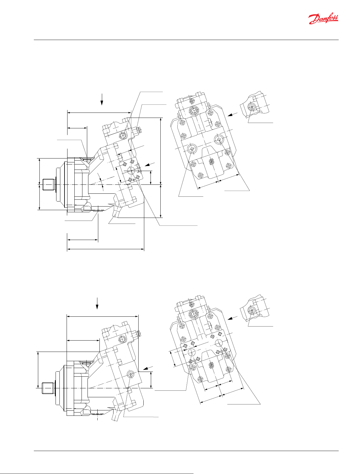
P001 801E
57.12
[2.25]
50.0
[1.97]
80.0
[3.15]
80.0
[3.15]
50.0
[1.97]
A
B
M4
27.76
[1.09]
58.0
[2.27]
127.0
[4.99]
249.0
[9.81]
115.0
[4.52]
77.0
[3.03]
77.0
[3.03]
A
B
M4
107.05
[4.21]
69.05
[2.72]
49.0
[1.92]
19°
223.0
[8.77]
268.2 max.
[10.56 max.]
93.5
[3.68]
88.5
[3.48]
232.8
[9.16]
115.0
[4.53]
27.76
[1.09]
57.12
[2.25]
W
Gauge port “M4”
System pressure max. angle
0.5625-18UNF-2B
[9/
16
-18UNF-2B]
W
W
Gauge port “M4”
System pressure max. angle
0.5625-18UNF-2B
[9/
16
-18UNF-2B]
W
Y
X
Y
Y
X
Y
Loop flushing
shuttle valve
Charge pressure
relief valve
min. angle stop
adjustment
Split flange boss “A”+”B”
DN 25 typ II 40 MPa series
per ISO 6162 [SAE 1.00]
4 thread: 0.4375-14UNC-2B
[7/
16
-14UNC-2B]
27 [1.06] min.
full thread depth
Case drain “L1”
1.0625-12UN-2B
[1 1/
16
-12UN-2B]
Alternate position
Case drain “L2”
1.0625-12UN-2B
[1 1/
16
-12UN-2B]
Gauge port “M1”
System pressure “A”
1.0625-12UNF-2B
[1 1/
16
-12UNF-2B]
Gauge port “M2”
System pressure “B”
1.0625-12UNF-2B
[1 1/
16
-12UNF-2B]
Gauge ports “M1”+”M2”
System pressure “A”+”B”
0.5625-18UNF-2B
[9/
16
-18UNF-2B]
Split flange boss “A”
DN 25 typ II 40 MPa series
per ISO 6162 [SAE 1.00]
4 thread: 0.4375-14UNC-2B
[7/
16
-14UNC-2B]
27 [1.06] min.
full thread depth
Split flange boss “B”
DN 25 typ II 40 MPa series
per ISO 6162 [SAE 1.00]
4 thread: 0.4375-14UNC-2B
[7/
16
-14UNC-2B]
27 [1.06] min.
full thread depth
Technical Information
Series 51 and 51-1 Bent Axis Variable Displ. Motors
General dimensions – frame size 110
DIN flange design per ISO 3019/2
51D110-1 two position control, N1NN (Side port on top, Axial port below)
©
Danfoss | October 2017 520L0440 | BC00000018en-US0401 | 85
Page 86

P001 802E
50.0
[1.97]
57.15
[2.25]
80.0
[3.15]
80.0
[3.15]
50.0
[1.97]
M3
M5
M4
A
B
27.76
[1.09]
Split flange boss “A”
DN 25 typ II 40 MPa series
per ISO 6162 [SAE 1.00]
4 thread: 0.4375-14UNC-2B
[7/
16
-14UNC-2B]
27 [1.06] min.
full thread depth
Split flange boss “B”
DN 25 typ II 40 MPa series
per ISO 6162 [SAE 1.00]
4 thread: 0.4375-14UNC-2B
[7/
16
-14UNC-2B]
27 [1.06] min.
full thread depth
Gauge port “M1”+”M2”
System pressure “A”+”B”
0.5625-18UNF-2B
[9/
16
-18UNF-2B]
268.0
[10.54]
64.0
[2.53]
125.0
[4.94]
111.0
[4.35]
Charge pressure
relief valve
107.05
[4.21]
69.05
[2.72]
Control start
adjustment
Gauge port “M3”
Servo pressure min. angle
0.5625-18UNF-2B
[9/
16
-18UNF-2B]
Gauge port “M5”
Servo pressure supply
0.5625-18UNF-2B
[9/
16
-18UNF-2B]
Control mounting
surface
Loop flushing
shuttle valve
305.0
[12.00]
88.5
[3.48]
93.5
[3.68]
185.0
[7.30]
103.0
[4.06]
49.0
[1.91]
222.0
[8.75]
19°
Case drain “L1”
1.0625-12UN-2B
[1 1/
16
-12UN-2B]
min. angle stop
adjustment
Gauge port “M7”
Control pressure
0.5625-18UNF-2B
[9/
16
-18UNF-2B]
114.0
[4.50]
A
M1
M5
M3
57.15
[2.25]
27.76
[1.09]
Split flange boss “A”+”B”
DN 25 typ II 40 MPa series
per ISO 6162 [SAE 1.00]
4 thread: 0.4375-14UNC-2B
[7/
16
-14UNC-2B]
27 [1.06] min.
full thread depth
Alternate position
Case drain “L2”
1.0625-12UN-2B
[1 1/
16
-12UN-2B]
Gauge port “M1”
System pressure “A”
0.5625-18UNF-2B
[9/
16
-18UNF-2B]
Gauge port “M2”
System pressure “B”
0.5625-18UNF-2B
[9/
16
-18UNF-2B]
77.0
[3.03]
77.0
[3.03]
Y
X
U
Y
Y
Y
X
Shaft centerline
Control pressure port “X1”
0.5625-18UNF-2B
[9/
16
-18UNF-2B]
U
X1
M7
49.0
[1.93]
Supply pressure
Shuttle valve
0.5625-18UNF-2B
[9/
16
-18UNF-2B]
Gauge port “M4”
Servo pressure max. angle
0.5625-18UNF-2B
[9/
16
-18UNF-2B]
W
W
M4
Supply pressure
Shuttle valve
0.5625-18UNF-2B
[9/
16
-18UNF-2B]
Gauge port “M4”
Servo pressure max. angle
0.5625-18UNF-2B
[9/
16
-18UNF-2B]
W
W
M4
Technical Information
Series 51 and 51-1 Bent Axis Variable Displ. Motors
General dimensions – frame size 110
51D110 proportional and two position control, HZB1 (Side port on top, Axial port below)
86 | © Danfoss | October 2017 520L0440 | BC00000018en-US0401
Page 87

P001 816E
ØG
ØA
ØD
Ø55.0
[2.17]
Ø116.0
[4.57]
H
F
E
B
C
Coupling may not protrude
beyond this surface
Ø160.0
- 0.063
[6.299
- 0.002
]
22.0
[0.87]
40.3
[1.59]
9.0
[0.35]
R2.5
[0.10]
Ø18.0 ± 0.2
[0.71 ± 0.01]
Ø30.0 [1.18]
other side max.
screw head space
70.7
[2.78]
70.7
[2.78]
190.0 ± 1.8
[7.48 ± 0.07]
70.7
[2.78]
70.7
[2.78]
190.0 ± 1.8
[7.48 ± 0.07]
Mounting flange surface
flange 160 B4 HL
per ISO 3019/2
13.5
[0.53]
Speed pick-up
Control pressure port “X1(M3)”
Servo pressure min. angle
0.5625-18UNF-2B
[9/
16
-18UNF-2B]
X
Z
Series 51 with
HZB1-control
Z
Series 51-1 with
N1NN-control
Z
Technical Information
Series 51 and 51-1 Bent Axis Variable Displ. Motors
General dimensions – frame size 110
Shaft options – 51D110-1 and 51D110
Shaft spline data - mm [in]
Shaft option D3 D4
Number of teeth 18 21
Spline W40x2x30x18x9g side fit DIN 5480 W45x2x30x21x9g side fit DIN 5480
Pitch Ø 36.0 [1.417] 42.0 [1.654]
Ø A 39.6 [1.56] 44.6 [1.76]
B 37.0 [1.46] 42.0 [1.65]
C 45.0±0.5 [1.77] 50.0±0.5 [1.97]
Ø D 35.0 [1.38] 40.0 [1.57]
E 47.3±1.1 [1.86] 52.3±1.1 [2.06]
F 85.3±0.6 [3.36] 90.3±0.6 [3.56]
H 30.0 [1.18] 30.0 [1.18]
Ø G M12x1.75 allowed torque in thread max. 115 N•m [1018 lbf•in]
Flow into port A results in CW rotation of output shaft.
Flow into port B results in CCW rotation of output shaft.
Shaft rotation is determined by viewing from shaft end. Ports with O-ring seal and inch threads shall be in
accordance with ISO 11926/1.
Splite flange boss A and B per ISO 6162 is identical with high pressure series SAEJ518 code 62 (6000 psi).
Contact your Danfoss representative for specific installation drawings.
©
Danfoss | October 2017 520L0440 | BC00000018en-US0401 | 87
Page 88

P001 803E
58.0
[2.27]
166.0
[6.55]
L1
19°
57.12
[2.25]
50.0
[1.97]
80.0
[3.15]
80.0
[3.15]
50.0
[1.97]
A
B
M4
27.76
[1.09]
77.0
[3.03]
77.0
[3.03]
A
B
M4
48.0
[1.89]
49.0
[1.92]
140.0
[5.51]
185.3 max.
[7.3 max.]
48.0
[1.89]
48.0
[1.89]
233.1
[9.18]
115.0
[4.53]
27.76
[1.09]
L1
57.12
[2.25]
Loop flushing
shuttle valve
Charge pressure
relief valve
min. angle stop
adjustment
Split flange boss “A”+”B”
DN 25 typ II 40 MPa series
per ISO 6162 [SAE 1.00]
4 thread: 0.4375-14UNC-2B
[7/
16
-14UNC-2B]
27 [1.06] min.
full thread depth
Case drain “L1”
1.0625-12UN-2B
[1 1/
16
-12UN-2B]
Alternate position
Case drain “L2”
1.0625-12UN-2B
[1 1/
16
-12UN-2B]
Gauge port “M1”
System pressure “A”
1.0625-12UNF-2B
[1 1/
16
-12UNF-2B]
Gauge port “M2”
System pressure “B”
1.0625-12UNF-2B
[1 1/
16
-12UNF-2B]
W
Gauge port “M4”
System pressure max. angle
0.5625-18UNF-2B
[9/
16
-18UNF-2B]
W
W
Gauge port “M4”
System pressure max. angle
0.5625-18UNF-2B
[9/
16
-18UNF-2B]
W
Y
X
Y
Gauge ports “M1”+”M2”
System pressure “A”+”B”
0.5625-18UNF-2B
[9/
16
-18UNF-2B]
Split flange boss “A”
DN 25 typ II 40 MPa series
per ISO 6162 [SAE 1.00]
4 thread: 0.4375-14UNC-2B
[7/
16
-14UNC-2B]
27 [1.06] min.
full thread depth
Split flange boss “B”
DN 25 typ II 40 MPa series
per ISO 6162 [SAE 1.00]
4 thread: 0.4375-14UNC-2B
[7/
16
-14UNC-2B]
27 [1.06] min.
full thread depth
Speed pick-up
Technical Information
Series 51 and 51-1 Bent Axis Variable Displ. Motors
General dimensions – frame size 110
Cartridge flange
51C110-1 two-position control, N1NN (Side port on top, Axial port below)
88 | © Danfoss | October 2017 520L0440 | BC00000018en-US0401
Page 89

L2
A
M3
M1
M5
N
L1
P001 804E
Gauge port “M2”
System pressure “B”
0.5625-18UNF-2B
[9/
16
-18UNF-2B]
Gauge port “M1”
System pressure “A”
0.5625-18UNF-2B
[9/
16
-18UNF-2B]
77.0
[3.03]
77.0
[3.03]
48.0
[1.89]
Control start
adjustment
Gauge port “M3”
Servo pressure min. angle
0.5625-18UNF-2B
[9/
16
-18UNF-2B]
Gauge port “M5”
Servo pressure supply
0.5625-18UNF-2B
[9/
16
-18UNF-2B]
Control mounting
surface
221.0
[8.71]
185.0 max.
[7.30] max.
103.0
[4.06]
49.0
[1.91]
140.0
[5.50]
Alternate position
Case drain “L2”
1.0625-12UN-2B
[1 1/
16
-12UN-2B]
Case drain “L1”
1.0625-12UN-2B
[1 1/
16
-12UN-2B]
Gauge port “M7”
Control pressure
0.5625-18UNF-2B
[9/
16
-18UNF-2B]
115.0 max.
[4.53] max.
57.15
[2.25]
27.76
[1.09]
Charge pressure
relief valve
Loop flushing
shuttle valve
Split flange boss “A”+”B”
DN 25 typ II 40 MPa series
per ISO 6162 [SAE 1.00]
4 thread: 0.4375-14UNC-2B
[7/
16
-14UNC-2B]
27 [1.06] min.
full thread depth
min. angle stop
adjustment
Speed pick-up
M3
M4
M5
A
B
27.66
[1.09]
50.0
[1.97]
50.0
[1.97]
80.0
[3.15]
80.0
[3.15]
57.15
[2.25]
Split flange boss “A”
DN 25 typ II 40 MPa series
per ISO 6162 [SAE 1.00]
4 thread: 0.4375-14UNC-2B
[7/
16
-14UNC-2B]
27 [1.06] min.
full thread depth
Split flange boss “B”
DN 25 typ II 40 MPa series
per ISO 6162 [SAE 1.00]
4 thread: 0.4375-14UNC-2B
[7/
16
-14UNC-2B]
27 [1.06] min.
full thread depth
Gauge port “M1”+”M2”
System pressure “A”+”B”
0.5625-18UNF-2B
[9/
16
-18UNF-2B]
185.0
[7.29]
64.0
[2.53]
19°
Shaft centerline
Control pressure port “X1”
0.5625-18UNF-2B
[9/
16
-18UNF-2B]
U
X1
M7
49.0
[1.93]
Supply pressure
Shuttle valve
0.5625-18UNF-2B
[9/
16
-18UNF-2B]
Gauge port “M4”
Servo pressure max. angle
0.5625-18UNF-2B
[9/
16
-18UNF-2B]
W
W
M4
Supply pressure
Shuttle valve
0.5625-18UNF-2B
[9/
16
-18UNF-2B]
Gauge port “M4”
Servo pressure max. angle
0.5625-18UNF-2B
[9/
16
-18UNF-2B]
W
W
M4
Y
X
U
Y
Y
Y
X
Technical Information
Series 51 and 51-1 Bent Axis Variable Displ. Motors
General dimensions – frame size 110
51C110 proportional and two-position control, HZB1 (Side port on top, Axial port below)
©
Danfoss | October 2017 520L0440 | BC00000018en-US0401 | 89
Page 90

P001 817E
125.0
[4.92]
125.0
[4.92]
Ø22.0 ± 0.3
[0.87 ± 0.01]
287.9
[11.33]
Ø30.0 [1.18]
other side max.
screw head space
ØG
ØA
Ø112.2
[4.42]
Ø160.0
[6.30]
H
B
45°
E
79.5
[3.13]
121.3
[4.78]
F
C
Coupling may not protrude
beyond this surface
11.2
[0.44]
20.0
[0.79]
Ø200.0
- 0.029
[7.874
- 0.001
]
R2.0
[0.10]
M3
ØD
Ø55.0
[2.17]
92.5
[3.64]
Ø136.0
[5.35]
21.2
[0.83]
Clearance
min. Ø293.5
[11.56]
92.5
[3.64]
O-ring 3.00x192.00 FPM
[0.12x7.56]
Mounting flange surface
cartridge flange
Alternate position
Case drain “L2”
1.0625-12UN-2B
[1 1/
16
-12UN-2B]
Case drain “L1”
1.0625-12UN-2B
[1 1/
16
-12UN-2B]
Control pressure port “X1(M3)”
Servo pressure min. angle
0.5625-18UNF-2B
[9/
16
-18UNF-2B]
X
Z
Series 51 with
HZB1-control
Z
Series 51-1 with
N1NN-control
Z
Technical Information
Series 51 and 51-1 Bent Axis Variable Displ. Motors
General dimensions – frame size 110
Shaft options – 51C110-1 and 51C110
Shaft spline data - mm [in]
Shaft option D3 D4
Number of teeth 18 21
Spline W40x2x30x18x9g side fit DIN 5480 W45x2x30x21x9g side fit DIN 5480
Pitch Ø 36.0 [1.417] 42.0 [1.654]
Ø A 39.6 [1.56] 44.6 [1.76]
B 37.0 [1.46] 42.0 [1.65]
C 45.0±0.5 [1.77] 50.0±0.5 [1.97]
Ø D 35.0 [1.38] 40.0 [1.57]
E 47.4±1.1 [1.87] 52.4±1.4 [2.06]
F 167.7±0.6 [6.6] 172.7±0.6 [6.8]
H 30.0 [1.18] 30.0 [1.18]
Ø G M12x1.75 allowed torque in thread max. 115 N•m [1018 lbf•in]
Flow into port A results in CW rotation of output shaft.
Flow into port B results in CCW rotation of output shaft.
Shaft rotation is determined by viewing from shaft end. Ports with O-ring seal and inch threads shall be in
accordance with ISO 11926/1.
Splite flange boss A and B per ISO 6162 is identical with high pressure series SAEJ518 code 62 (6000 psi).
Contact your Danfoss representative for specific installation drawings.
90 | © Danfoss | October 2017 520L0440 | BC00000018en-US0401
Page 91
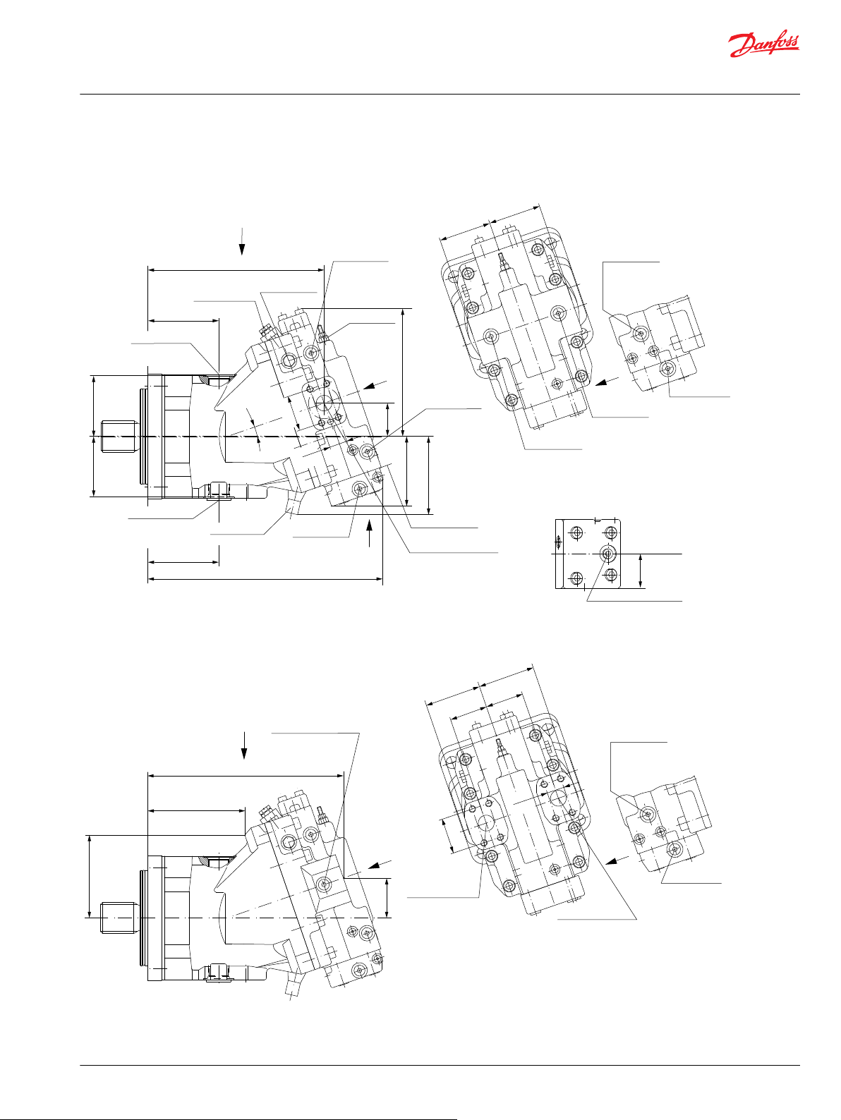
M3
M5
M1
A
L1
L2
P001 805E
60.0
[2.36]
57.15
[2.25]
60.0
[2.36]
91.0
[3.58]
91.0
[3.58]
A
B
M5
M4
M3
27.76
[1.09]
Split flange boss “A”
DN 25 typ II 40 MPa series
per ISO 6162 [SAE 1.00]
4 thread: 0.4375-14UNC-2B
[7/
16
-14UNC-2B]
27 [1.06] min.
full thread depth
Split flange boss “B”
DN 25 typ II 40 MPa series
per ISO 6162 [SAE 1.00]
4 thread: 0.4375-14UNC-2B
[7/
16
-14UNC-2B]
27 [1.06] min.
full thread depth
Gauge port “M1”+”M2”
System pressure “A”+”B”
0.5625-18UNF-2B
[9/
16
-18UNF-2B]
313.0
[12.34]
64.0
[2.52]
144.0
[5.68]
165.0
[6.51]
Gauge port “M2”
System pressure “B”
0.5625-18UNF-2B
[9/
16
-18UNF-2B]
Gauge port “M1”
System pressure “A”
0.5625-18UNF-2B
[9/
16
-18UNF-2B]
84.0
[3.31]
84.0
[3.31]
114.0
[4.47]
114.0
[4.47]
Control start
adjustment
Gauge port “M3”
Servo pressure min. angle
0.5625-18UNF-2B
[9/
16
-18UNF-2B]
Gauge port “M5”
Servo pressure supply
0.5625-18UNF-2B
[9/
16
-18UNF-2B]
Control mounting
surface
Loop flushing
shuttle valve
376.0
[14.82]
97.0
[3.82]
97.0
[3.82]
205.0
[8.08]
111.0
[4.37]
53.0
[2.10]
282.0
[11.11]
Alternate position
Case drain “L2”
1.3125-12UN-2B
[1 5/16-12UN-2B]
19°
Gauge port “M7”
Control pressure
0.5625-18UNF-2B
[9/
16
-18UNF-2B]
125.0
[4.94]
27.76
[1.09]
57.15
[2.25]
Split flange boss “A”+”B”
DN 25 typ II 40 MPa series
per ISO 6162 [SAE 1.00]
4 thread: 0.4375-14UNC-2B
[7/
16
-14UNC-2B]
27 [1.06] min.
full thread depth
min. angle stop
adjustment
L1
L2
Y
X
U
Y
Y
Y
X
Charge pressure
relief valve
Case drain “L1”
1.3125-12UN-2B
[1 5/16-12UN-2B]
Shaft centerline
Control pressure port “X1”
0.5625-18UNF-2B
[9/
16
-18UNF-2B]
U
X1
M7
49.0
[1.93]
Supply pressure
Shuttle valve
0.5625-18UNF-2B
[9/
16
-18UNF-2B]
Gauge port “M4”
Servo pressure max. angle
0.5625-18UNF-2B
[9/
16
-18UNF-2B]
W
W
M4
Supply pressure
Shuttle valve
0.5625-18UNF-2B
[9/
16
-18UNF-2B]
Gauge port “M4”
Servo pressure max. angle
0.5625-18UNF-2B
[9/
16
-18UNF-2B]
W
W
M4
Technical Information
Series 51 and 51-1 Bent Axis Variable Displ. Motors
General dimensions – frame size 160
SAE flange design per ISO 3019/1
51V160 proportional and two-position control, HZB1 (Side port on top, Axial port below)
©
Danfoss | October 2017 520L0440 | BC00000018en-US0401 | 91
Page 92
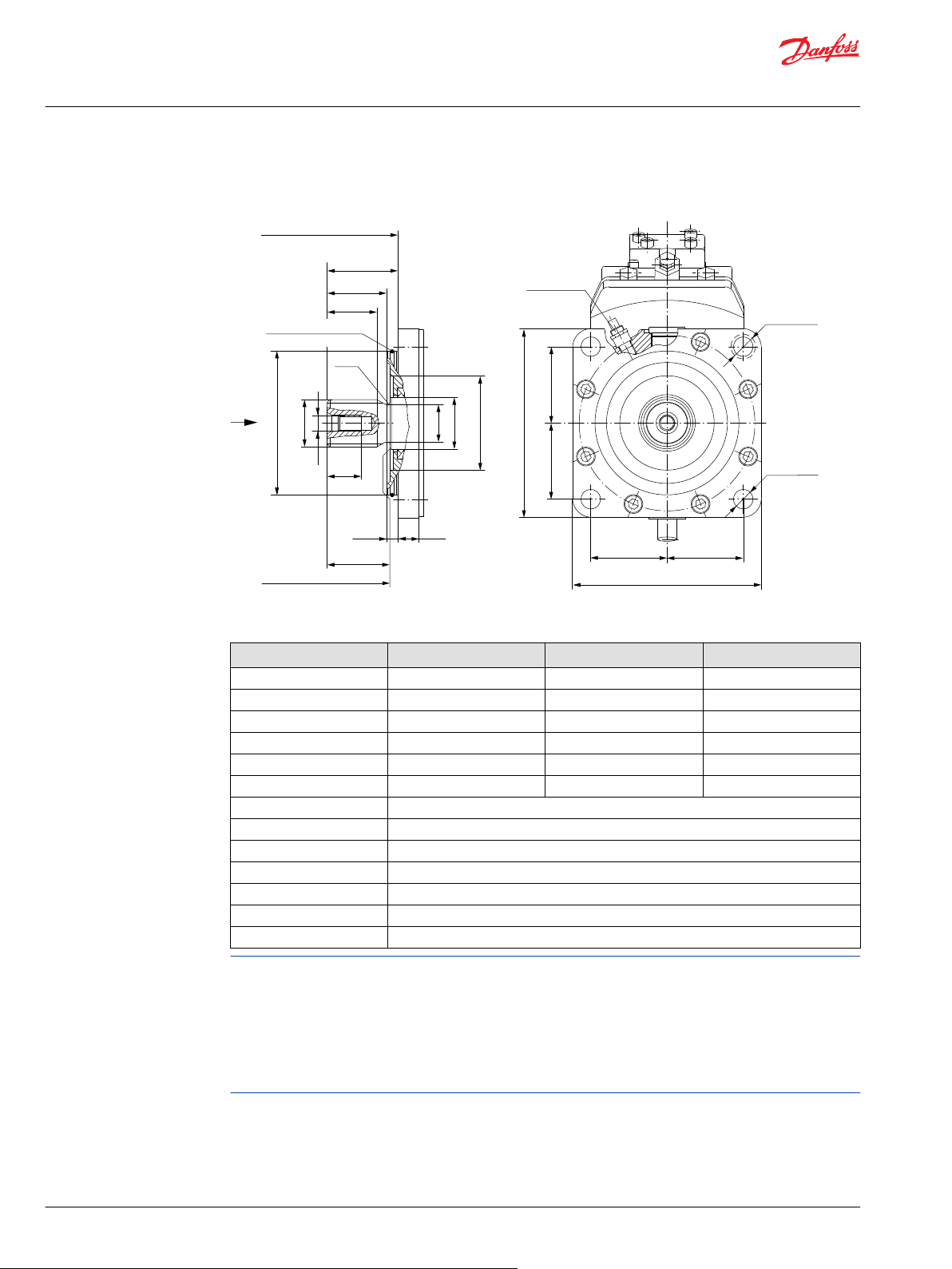
Ø152.375 ± 0.025
[5.999 ± 0.001]
Ø100.0
[3.94]
Ø55.0
[2.17]
ØG
ØA
ØD
H
F
E
B
C
Coupling may not protrude
beyond this surface
12.45
[0.49]
22.0
[0.87]
R3.0
[0.12]
P001 818E
80.8
[3.18]
80.8
[3.18]
Ø20.5 ± 0.2
[0.81 ± 0.01]
80.8
[3.18]
80.8
[3.18]
200.0 ± 1.8
[7.87 ± 0.07]
200.0 ± 1.8
[7.87 ± 0.07]
Speed pick-up
Mounting flange surface
flange 152-4 (SAE "D")
per ISO 3019/1
O-ring 3.00x142.00 FPM
[0.12x5.59]
Ø30.0 [1.18]
other side max.
screw head space
Z
X
Z
Technical Information
Series 51 and 51-1 Bent Axis Variable Displ. Motors
General dimensions – frame size 160
Shaft options – 51V160
Shaft spline data - mm [in]
Shaft option F1 F2 C8
Number of teeth 13 15 27
Pitch 8/16 8/16 16/32
Pitch Ø 41.275 [1.625] 47.625 [1.875] 42.862 [1.688]
Ø A 43.64 [1.72] 49.99 [1.97] 43.96 [1.73]
B 55.0 [2.17] 53.0 [2.09] 55.0 [2.17]
Ø D 36.0 [1.42] 42.20 [1.66] 39.60 [1.56]
Pressure angle 30°
C 67.0±0.5 [2.64]
E 70.0±1.1 [2.76]
H 36.0 [1.42]
F 75.40±0.7 [2.97]
Spline ANSI B92.1-1970, class 5, flat root side fit
Ø G 0.625-11UNC-2B [5/8-11UNC-2B]; allowed torque in thread max. 200 N•m [1770 lbf•in]
Flow into port A results in CW rotation of output shaft.
Flow into port B results in CCW rotation of output shaft.
Shaft rotation is determined by viewing from shaft end. Ports with O-ring seal and inch threads shall be in
accordance with ISO 11926/1.
Splite flange boss A and B per ISO 6162 is identical with high pressure series SAEJ518 code 62 (6000 psi).
Contact your Danfoss representative for specific installation drawings.
92 | © Danfoss | October 2017 520L0440 | BC00000018en-US0401
Page 93

P001 806E
281.0
[11.08]
64.0
[2.53]
138.0
[5.44]
122.0
[4.80]
60.0
[2.36]
57.15
[2.25]
91.0
[3.58]
91.0
[3.58]
60.0
[2.36]
M4
M5
M3
B
A
27.76
[1.09]
84.0
[3.31]
84.0
[3.31]
121.5
[4.78]
81.0
[3.21]
345.0
[13.60]
95.5
[3.76]
103.0
[4.06]
205.0
[8.08]
111.0
[4.37]
53.0
[2.10]
250.0
[9.85]
19°
125.0
[4.94]
A
M1
M5
M3
27.76
[1.09]
57.15
[2.25]
Split flange boss “A”
DN 25 typ II 40 MPa series
per ISO 6162 [SAE 1.00]
4 thread: 0.4375-14UNC-2B
[7/
16
-14UNC-2B]
27 [1.06] min.
full thread depth
Split flange boss “B”
DN 25 typ II 40 MPa series
per ISO 6162 [SAE 1.00]
4 thread: 0.4375-14UNC-2B
[7/
16
-14UNC-2B]
27 [1.06] min.
full thread depth
Gauge port “M1”+”M2”
System pressure “A”+”B”
0.5625-18UNF-2B
[9/
16
-18UNF-2B]
Y
Y
X
Control start
adjustment
Gauge port “M3”
Servo pressure min. angle
0.5625-18UNF-2B
[9/
16
-18UNF-2B]
Gauge port “M5”
Servo pressure supply
0.5625-18UNF-2B
[9/
16
-18UNF-2B]
Control mounting
surface
Loop flushing
shuttle valve
Alternate position
Case drain “L2”
1.3125-12UN-2B
[1 5/
16
-12UN-2B]
Gauge port “M7”
Control pressure
0.5625-18UNF-2B
[9/
16
-18UNF-2B]
Split flange boss “A”+”B”
DN 25 typ II 40 MPa series
per ISO 6162 [SAE 1.00]
4 thread: 0.4375-14UNC-2B
[7/
16
-14UNC-2B]
27 [1.06] min.
full thread depth
min. angle stop
adjustment
Y
X
Charge pressure
relief valve
Case drain “L1”
1.3125-12UN-2B
[1 5/
16
-12UN-2B]
Gauge port “M2”
System pressure “B”
0.5625-18UNF-2B
[9/
16
-18UNF-2B]
Gauge port “M1”
System pressure “A”
0.5625-18UNF-2B
[9/
16
-18UNF-2B]
Y
Shaft centerline
Control pressure port “X1”
0.5625-18UNF-2B
[9/
16
-18UNF-2B]
U
X1
M7
49.0
[1.93]
Supply pressure
Shuttle valve
0.5625-18UNF-2B
[9/
16
-18UNF-2B]
Gauge port “M4”
Servo pressure max. angle
0.5625-18UNF-2B
[9/
16
-18UNF-2B]
W
W
M4
Supply pressure
Shuttle valve
0.5625-18UNF-2B
[9/
16
-18UNF-2B]
Gauge port “M4”
Servo pressure max. angle
0.5625-18UNF-2B
[9/
16
-18UNF-2B]
W
W
M4
U
Technical Information
Series 51 and 51-1 Bent Axis Variable Displ. Motors
General dimensions – frame size 160
DIN flange design per ISO 3019/2
51D160 proportional and two-position control, HZB1 (Side port on top, Axial port below)
©
Danfoss | October 2017 520L0440 | BC00000018en-US0401 | 93
Page 94

ØG
ØA
ØD
Ø55.0
[2.17]
Ø120.0
[4.72]
H
F
E
B
C
Coupling may not protrude
beyond this surface
Ø180.0
- 0.063
[7.087
- 0.002
]
25.0
[0.99]
40.0
[1.59]
9.0
[0.35]
9.0
[0.35]
R1.6
[0.06]
P001 819E
Speed pick-up
Ø18.0 ± 0.2
[0.71 ± 0.01]
79.2
[3.12]
79.2
[3.12]
212.0 ± 1.8
[8.35 ± 0.07]
79.2
[3.12]
79.2
[3.12]
212.0 ± 1.8
[8.35 ± 0.07]
Ø130.0
(5.12)
Mounting flange surface
flange 180 B4 HL
per ISO 3019/2
Ø30.0 [1.18]
other side max.
screw head space
Z
X
Z
Technical Information
Series 51 and 51-1 Bent Axis Variable Displ. Motors
General dimensions – frame size 160
Shaft options – 51D160
Shaft spline data - mm [in]
Shaft option D4 D5
Number of teeth 21 24
Spline W45x2x30x21x9g side fit DIN 5480 W50x2x30x24x9g side fit DIN 5480
Pitch Ø 42.0 [1.654] 48.0 [1.890]
Ø A 44.6 [1.76] 49.6 [1.95]
B 42.0 [1.65] 47.0 [1.85]
C 50.0±0.5 [1.97] 55.0±0.5 [2.17]
Ø D 40.0 [1.57] 45.0 [1.77]
E 52.3±1.1 [2.06] 57.3±1.1 [2.26]
F 90.3±0.6 [3.56] 95.3±0.6 [3.75]
H 30.0 [1.18] 30.0 [1.18]
Ø G M12x1.75 allowed torque in thread max. 115 N•m [1018 lbf•in]
Flow into port A results in CW rotation of output shaft.
Flow into port B results in CCW rotation of output shaft.
Shaft rotation is determined by viewing from shaft end. Ports with O-ring seal and inch threads shall be in
accordance with ISO 11926/1.
Splite flange boss A and B per ISO 6162 is identical with high pressure series SAEJ518 code 62 (6000 psi).
Contact your Danfoss representative for specific installation drawings.
94 | © Danfoss | October 2017 520L0440 | BC00000018en-US0401
Page 95

P001 807E
B
A
M4
M5
M3
60.0
[2.36]
91.0
[3.58]
91.0
[3.58]
60.0
[2.36]
57.15
[2.25]
27.76
[1.09]
L1
177.0
[6.96]
64.0
[2.52]
19°
84.0
[3.31]
84.0
[3.31]
L1
M5
M1
M3
A
146.0
[5.73]
54.0
[2.13]
239.0
[9.40]
205.0
[8.08]
125.0
[4.94]
53.0
[2.1]
111.0
[4.37]
57.15
[2.25]
27.76
[1.09]
51.0
[2.01]
51.0
[2.01]
Control start
adjustment
Gauge port “M3”
Servo pressure min. angle
0.5625-18UNF-2B
[9/
16
-18UNF-2B]
Gauge port “M5”
Servo pressure supply
0.5625-18UNF-2B
[9/
16
-18UNF-2B]
Control mounting
surface
Loop flushing
shuttle valve
Alternate position
Case drain “L2”
1.3125-12UN-2B
[1 5/
16
-12UN-2B]
Gauge port “M7”
Control pressure
0.5625-18UNF-2B
[9/
16
-18UNF-2B]
Split flange boss “A”+”B”
DN 25 typ II 40 MPa series
per ISO 6162 [SAE 1.00]
4 thread: 0.4375-14UNC-2B
[7/
16
-14UNC-2B]
27 [1.06] min.
full thread depth
min. angle stop
adjustment
Charge pressure
relief valve
Case drain “L1”
1.3125-12UN-2B
[1 5/
16
-12UN-2B]
Gauge port “M2”
System pressure “B”
0.5625-18UNF-2B
[9/
16
-18UNF-2B]
Gauge port “M1”
System pressure “A”
0.5625-18UNF-2B
[9/
16
-18UNF-2B]
Y
X
Y
U
Shaft centerline
Control pressure port “X1”
0.5625-18UNF-2B
[9/
16
-18UNF-2B]
U
X1
M7
49.0
[1.93]
Supply pressure
Shuttle valve
0.5625-18UNF-2B
[9/
16
-18UNF-2B]
Gauge port “M4”
Servo pressure max. angle
0.5625-18UNF-2B
[9/
16
-18UNF-2B]
W
W
M4
Supply pressure
Shuttle valve
0.5625-18UNF-2B
[9/
16
-18UNF-2B]
Gauge port “M4”
Servo pressure max. angle
0.5625-18UNF-2B
[9/
16
-18UNF-2B]
W
W
M4
Split flange boss “A”
DN 25 typ II 40 MPa series
per ISO 6162 [SAE 1.00]
4 thread: 0.4375-14UNC-2B
[7/
16
-14UNC-2B]
27 [1.06] min.
full thread depth
Split flange boss “B”
DN 25 typ II 40 MPa series
per ISO 6162 [SAE 1.00]
4 thread: 0.4375-14UNC-2B
[7/
16
-14UNC-2B]
27 [1.06] min.
full thread depth
Gauge port “M1”+”M2”
System pressure “A”+”B”
0.5625-18UNF-2B
[9/
16
-18UNF-2B]
Y
Y
X
Technical Information
Series 51 and 51-1 Bent Axis Variable Displ. Motors
General dimensions – frame size 160
Cartridge flange
51C160 proportional and two-position control, HZB1 (Side port on top, Axial port below)
©
Danfoss | October 2017 520L0440 | BC00000018en-US0401 | 95
Page 96

P001 820E
140.0
[5.51]
140.0
[5.51]
Ø22.0 ± 0.3
[0.87 ± 0.01]
318.0 ± 2.0
[12.52 ± 0.08]
11.2
[0.44]
140.8 max.
[5.54 max.]
20.03
[0.79]
Alternate position
Case drain “L2”
1.3125-12UN-2B
[1 5/
16
-12UN-2B]
104.0
[4.09]
104.0
[4.09]
Ø230.0
- 0.029
[9.055
- 0.001
]
Ø184.0
[7.24]
Case drain “L1”
1.3125-12UN-2B
[1 5/
16
-12UN-2B]
B
E
96.0
[3.78]
F
H
C
Coupling may not protrude
beyond this surface
ØG
ØA
Ø120.0
[4.72]
Ø142.0
[5.59]
Ø55.0
[2.17]
ØD
45°
Clearance
min. Ø323.6
[12.74]
O-ring 3.00x220.00 FPM
[0.12x8.66]
Mounting flange surface
cartridge flange
Z
X
Z
Ø30.0 [1.18]
other side max.
screw head space
Technical Information
Series 51 and 51-1 Bent Axis Variable Displ. Motors
General dimensions – frame size 160
Shaft options – 51C160
Shaft spline data - mm [in]
Shaft option D4 D5
Number of teeth 21 24
Spline W45x2x30x21x9g side fit DIN 5480 W50x2x30x24x9g side fit DIN 5480
Pitch Ø 42.0 [1.654] 48.0 [1.890]
Ø A 44.6 [1.76] 49.6 [1.95]
B 42.0 [1.65] 47.0 [1.85]
C 50.0±0.5 [1.97] 55.0±0.5 [2.17]
Ø D 40.0 [1.57] 45.0 [1.77]
E 54.5±1.4 [2.15] 59.5±1.4 [2.34]
F 194.9±0.6 [7.67] 199.9±0.6 [7.87]
H 30.0 [1.18] 30.0 [1.18]
Ø G M12x1.75 allowed torque in thread max. 115 N•m [1018 lbf•in]
Flow into port A results in CW rotation of output shaft.
Flow into port B results in CCW rotation of output shaft.
Shaft rotation is determined by viewing from shaft end. Ports with O-ring seal and inch threads shall be in
accordance with ISO 11926/1.
Splite flange boss A and B per ISO 6162 is identical with high pressure series SAEJ518 code 62 (6000 psi).
Contact your Danfoss representative for specific installation drawings.
96 | © Danfoss | October 2017 520L0440 | BC00000018en-US0401
Page 97

A
M5
M3
M1
L2
L1
P001 808E
359.0
[14.13]
74.0
[2.90]
155.0
[6.11]
182.0
[7.15]
97.0
[3.82]
97.0
[3.82]
131.5
[5.18]
131.5
[5.18]
429.0
[16.89]
239.0
[9.39]
120.0
[4.71]
62.0
[2.44]
325.0
[12.79]
19°
137.0
[5.4]
31.76
[1.25]
66.68
[2.63]
113.0
[4.45]
113.0
[4.45]
M5
M4
M3
A
B
66.68
[2.63]
31.76
[1.25]
65.0
[2.56]
65.0
[2.56]
99.0
[3.90]
99.0
[3.90]
L2
L1
Split flange boss “A”
DN 32 typ II 40 MPa series
per ISO 6162 [SAE 1.25]
4 thread: 0.5-13UNC-2B
[1/2 -13UNC-2B]
25 [0.98] min.
full thread depth
Split flange boss “B”
DN 32 typ II 40 MPa series
per ISO 6162 [SAE 1.25]
4 thread: 0.5-13UNC-2B
[1/2 -13UNC-2B]
25 [0.98] min.
full thread depth
Gauge port “M1”+”M2”
System pressure “A”+”B”
0.5625-18UNF-2B
[9/
16
-18UNF-2B]
Y
Y
X
Control mounting
surface
Alternate position
Case drain “L2”
1.3125-12UN-2B
[1 5/16-12UN-2B]
Gage port “M7”
Control pressure
0.5625-18UNF-2B
[9/
16
-18UNF-2B]
Split flange boss “A”+”B”
DN 32 typ II 40 MPa series
per ISO 6162 [SAE 1.25]
4 thread: 0.5-13UNC-2B
[1/2 -13UNC-2B]
25 [0.98] min.
full thread depth
min. angle stop
adjustment
Loop flushing
shuttle valve
Charge pressure
relief valve
Case drain “L1”
1.3125-12UN-2B
[1 5/16-12UN-2B]
Gauge port “M3”
Servo pressure min. angle
0.5625-18UNF-2B
[9/
16
-18UNF-2B]
Gauge port “M5”
Servo pressure supply
0.5625-18UNF-2B
[9/
16
-18UNF-2B]
Control start
adjustment
Gauge port “M1”
System pressure “A”
0.5625-18UNF-2B
[9/
16
-18UNF-2B]
Gauge port “M2”
System pressure “B”
0.5625-18UNF-2B
[9/
16
-18UNF-2B]
Supply pressure
Shuttle valve
0.5625-18UNF-2B
[9/
16
-18UNF-2B]
Gauge port “M4”
Servo pressure max. angle
0.5625-18UNF-2B
[9/
16
-18UNF-2B]
W
W
M4
Supply pressure
Shuttle valve
0.5625-18UNF-2B
[9/
16
-18UNF-2B]
Gauge port “M4”
Servo pressure max. angle
0.5625-18UNF-2B
[9/
16
-18UNF-2B]
W
W
M4
Shaft centerline
Control pressure port “X1”
0.5625-18UNF-2B
[9/
16
-18UNF-2B]
U
X1
M7
49.0
[1.93]
Y
X
Y
U
Technical Information
Series 51 and 51-1 Bent Axis Variable Displ. Motors
General dimensions – frame size 250
SAE flange design per ISO 3019/1
51V250 Proportional and Two-Position Control, HZB1 (Side port on top, Axial port below)
©
Danfoss | October 2017 520L0440 | BC00000018en-US0401 | 97
Page 98

Ø165.075 ± 0.025
[6.499 ± 0.001]
Ø100.0
[3.94]
Ø55.0
[2.17]
ØG
ØA
ØD
Ø118.0
[4.65]
36.0
[1.42]
F
E
B
C
Coupling may not protrude
beyond this surface
15.65
[0.62]
25.0
[0.98]
R3.0
[0.12]
Speed pick-up
Ø20.5 ± 0.2
[0.81 ± 0.01]
P001 821E
112.25
[4.42]
112.25
[4.42]
260.0 ± 1.9
[10.24 ± 0.07]
112.25
[4.42]
112.25
[4.42]
260.0 ± 1.9
[10.24 ± 0.07]
O-ring 3.00x154.00 FPM
[0.12x6.06]
Mounting flange surface
flange 165-4 (SAE "E")
per ISO 3019/1
Ø30.0 [1.18]
other side max.
screw head space
Z
X
Z
Technical Information
Series 51 and 51-1 Bent Axis Variable Displ. Motors
General dimensions – frame size 250
Shaft Options – 51V250
Shaft spline data - mm [in]
Shaft option F2 C8
Number of teeth 15 27
Pitch 8/16 16/32
Pitch Ø 47.625 [1.875] 42.862 [1.688]
Ø A 49.99 [1.97] 43.96 [1.73]
B 53.0 [2.09] 55.0 [2.17]
Ø D 42.20 [1.66] 39.60 [1.56]
Pressure angle 30°
C 67.0 ±0.5 [2.64]
E 70.0 ±1.1 [2.76]
F 75.4 ±0.7 [2.97]
H 36.0 [1.42]
Spline ANSI B92.1-1970, class 5, flat root side fit
Ø G 0.625-11UNC-2B [5/8-11UNC-2B]; allowed torque in thread max. 200 N•m [1770 lbf•in]
Flow into port A results in CW rotation of output shaft.
Flow into port B results in CCW rotation of output shaft.
Shaft rotation is determined by viewing from shaft end. Ports with O-ring seal and inch threads shall be in
accordance with ISO 11926/1.
Splite flange boss A and B per ISO 6162 is identical with high pressure series SAEJ518 code 62 (6000 psi).
Contact your Danfoss representative for specific installation drawings.
98 | © Danfoss | October 2017 520L0440 | BC00000018en-US0401
Page 99

P001 838E
AC
75.0
[2.94]
55.0
[2.17]
128.2
[5.05]
AB
Flange
AA
55.0
[2.17]
Solenoid for
Electric brake pressure defeat
X1
M3
XA
XB
X1
M3
XA
XB
Shaft centerline
Shaft centerline
Control pressure port “XA”
0.5625-18UNF-2B
[9/
16
-18UNF-2B]
Control pressure port “XB”
0.5625-18UNF-2B
[9/
16
-18UNF-2B]
Z
Z
Electric brake
pressure defeat
TAD*
Z
Hydraulic brake
pressure defeat
TACA
A B
P001752
2 1
P001751
Technical Information
Series 51 and 51-1 Bent Axis Variable Displ. Motors
Dimension – Controls
Options TA** for 51-1 – Pressure Compensator Control (Frame Size: 060, 080, 110)
Control TA** for 51-1 - mm [in]
Frame 060 080 110
Design V D C V D C V D C
AA 181.2
[7.13]
AB 199.3 [7.85] 209.7 [8.26] 223.5 [8.80] 223.9
AC 176.4 [6.95] 186.8 [7.36] 200.6 [7.90] 201.0
V = SAE-flange
D = DIN-flange
C = Cartridge flange
156.7
[6.17]
96.9
[3.82]
196.9
[7.75]
172.9
[6.81]
94.5
[3.72]
213.4
[8.40]
181.8
[7.16]
99.0
[3.90]
[8.82]
[7.91]
Solenoid connectors
Plug face DIN 46350 (Supplied)
Mating connector No.: K09129
Id. No.: 514117
AMP Junior Timer two pin (Supplied)
Mating connector No.: K19815
Id. No.: 508388
Shaft rotation is determined by viewing from shaft end. Ports with O-ring seal and inch threads shall be in
accordance with ISO 11926/1. Splite flange boss A and B per ISO 6162 is identical with high pressure
series SAEJ518 code 62 (6000 psi). Contact your Danfoss representative for specific installation drawings.
©
Danfoss | October 2017 520L0440 | BC00000018en-US0401 | 99
Page 100
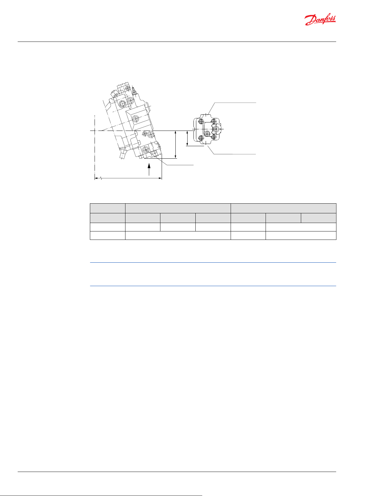
Flange
JA
JB
58.0
[2.28]
Shaft centerline
Supply pressure
Shuttle valve
0.5625-18UNF-2B
[9/
16
-18UNF-2B]
Control pressure port “XA”
0.5625-18UNF-2B
[9/
16
-18UNF-2B]
Control pressure port “XB”
0.5625-18UNF-2B
[9/
16
-18UNF-2B]
P001 839E
Z
Z
Control option
TAC2
X1
XB
XA
X4
Technical Information
Series 51 and 51-1 Bent Axis Variable Displ. Motors
Dimension – Controls
Options TA** for 51 – Pressure Compensator Control (Frame Size: 160, 250)
Control TA** for 51 - mm [in]
Frame 160 250
Design V D C V D C
JA 393 [15.48] 361 [14.22] 257 [10.11] 445 [17.51] –
JB 114 [4.48] 122 [4.82] –
V = SAE-flange
D = DIN-flange
C = Cartridge flange
Shaft rotation is determined by viewing from shaft end. Ports with O-ring seal and inch threads shall be in
accordance with ISO 11926/1. Splite flange boss A and B per ISO 6162 is identical with high pressure
series SAEJ518 code 62 (6000 psi). Contact your Danfoss representative for specific installation drawings.
100 | © Danfoss | October 2017 520L0440 | BC00000018en-US0401
 Loading...