

Danfoss Series 51-1 Controls B1, Series 51-1 Controls B2, Series 51-1 Controls B7, Series 51-1 Controls E1, Series 51-1 Controls E2 Service guide
...Page 1
MAKING MODERN LIVING POSSIBLE
Service Manual
Series 51-1 Controls B1, B2, B7,
E1, E2, E7, F1, F2, N1, T1, T2, T7,
TA, TH, P7, P8
powersolutions.danfoss.com
Page 2

Service Manual Series 51-1 Controls B1, B2, B7, E1, E2, E7, F1, F2, N1, T1, T2, T7, TA, TH, P7, P8
Revision history Table of revisions
Date Changed Rev
February 2015 Danfoss layout BA
January 2008 First edition AA
2 11009443 • Rev BA • February 2015
Page 3

Service Manual
Series 51-1 Controls B1, B2, B7, E1, E2, E7, F1, F2, N1, T1, T2, T7, TA, TH, P7, P8
Contents
Introduction
Safety precautions............................................................................................................................................................................4
Unintended machine movement..........................................................................................................................................4
Flammable cleaning solvents.................................................................................................................................................4
Fluid under pressure..................................................................................................................................................................4
Personal safety............................................................................................................................................................................. 4
Hazardous material.................................................................................................................................................................... 4
Symbols used in Danfoss literature............................................................................................................................................5
General instructions........................................................................................................................................................................ 5
Keep it clean..................................................................................................................................................................................5
Inspect for system contamination........................................................................................................................................ 6
Replace the O-rings and gaskets........................................................................................................................................... 6
Lubricate all moving parts....................................................................................................................................................... 6
Torque procedure.......................................................................................................................................................................6
Overview..............................................................................................................................................................................................6
Required tools, gauge port and orifice locations
Required tools....................................................................................................................................................................................8
Port locations and gauge installation....................................................................................................................................... 8
Orifice locations................................................................................................................................................................................ 9
N1 two-position control
Functional Description.................................................................................................................................................................10
Adjustments.....................................................................................................................................................................................10
Minor repair......................................................................................................................................................................................10
E1, E2, E7, F1, F2 two-position controls
Functional description................................................................................................................................................................. 13
Adjustments.....................................................................................................................................................................................14
Minor repair......................................................................................................................................................................................14
B1, B2, B7 two-position controls
Functional description................................................................................................................................................................. 17
Adjustments.....................................................................................................................................................................................17
Minor repair......................................................................................................................................................................................17
T1, T2, T7, TA, TH Pressure Compensator (PC) controls
Functional Description.................................................................................................................................................................20
Overview......................................................................................................................................................................................20
Option TA.................................................................................................................................................................................... 20
Option TH.................................................................................................................................................................................... 20
Option T1T2/T7 .........................................................................................................................................................................21
Brake pressure defeat..............................................................................................................................................................21
Schematics.................................................................................................................................................................................. 23
Adjustment.......................................................................................................................................................................................24
PC start pressure....................................................................................................................................................................... 24
Minor repair......................................................................................................................................................................................26
Control housing........................................................................................................................................................................ 26
TA option components...........................................................................................................................................................27
TH option components.......................................................................................................................................................... 28
T1, T2, T7 option components............................................................................................................................................. 29
Servo/PC supply option CA (with hydraulic signal)..................................................................................................... 30
Servo/PC supply option C2 (without external signal)................................................................................................. 31
Servo/PC supply options D1/D2/D7.................................................................................................................................. 32
Servo/PC supply options L5/R5........................................................................................................................................... 34
11009443 • Rev BA • February 2015 3
Page 4

W
W
W
W
W
Service Manual
Introduction
Safety precautions
Series 51-1 Controls B1, B2, B7, E1, E2, E7, F1, F2, N1, T1, T2, T7, TA, TH, P7, P8
Always consider safety precautions before beginning a service procedure. Protect yourself and others
from injury. Take the following general precautions whenever servicing a hydraulic system.
Unintended machine movement
Warning
Unintended movement of the machine or mechanism may cause injury to the technician or bystanders.
To protect against unintended movement, secure the machine or disable/disconnect the mechanism
while servicing.
Flammable cleaning solvents
Warning
Some cleaning solvents are flammable. To avoid possible fire, do not use cleaning solvents in an area
where a source of ignition may be present.
Fluid under pressure
Warning
Escaping hydraulic fluid under pressure can have sufficient force to penetrate your skin causing serious
injury and/or infection. This fluid may also be hot enough to cause burns. Use caution when dealing with
hydraulic fluid under pressure. Relieve pressure in the system before removing hoses, fittings, gauges, or
components. Never use your hand or any other body part to check for leaks in a pressurized line. Seek
medical attention immediately if you are cut by hydraulic fluid.
Personal safety
Warning
Protect yourself from injury. Use proper safety equipment, including safety glasses, at all times.
Hazardous material
Warning
Hydraulic fluid contains hazardous material. Avoid prolonged contact with hydraulic fluid. Always
dispose of used hydraulic fluid acm³ording to state, and federal environmental regulations.
4 11009443 • Rev BA • February 2015
Page 5

Service Manual
Series 51-1 Controls B1, B2, B7, E1, E2, E7, F1, F2, N1, T1, T2, T7, TA, TH, P7, P8
Introduction
Symbols used in Danfoss literature
WARNING may result in injury Tip, helpful suggestion
CAUTION may result in damage to product or
property
Reusable part Apply grease / petroleum jelly
Non-reusable part, use a new part Apply locking compound
Non-removable item Inspect for wear or damage
Option - either part may exist Clean area or part
Superseded - parts are not interchangeable Be careful not to scratch or damage
Measurement required Note correct orientation
Flatness specification Mark orientation for reinstallation
Parallelism specification Torque specification
External hex head Press in - press fit
Internal hex head Pull out with tool – press fit
Torx head Cover splines with installation sleeve
Lubricate with hydraulic fluid
General instructions
O-ring boss port Pressure measurement/gauge location or
specification
The symbols above appear in the illustrations and text of this manual. They are intended to communicate
helpful information at the point where it is most useful to the reader. In most instances, the appearance
of the symbol itself denotes its meaning. The legend above defines each symbol and explains its purpose.
Keep it clean
You can complete many repairs or adjustments without removing the unit from the machine, if the
unit is accessible and you can thoroughly clean it before beginning any procedures.
Cleanliness is a primary means of assuring satisfactory motor life on either new or repaired units. Clean
the outside of the motor thoroughly before disassembly. Take care to avoid contamination of the system
ports. Cleaning parts with a clean solvent wash and air drying is usually adequate.
As with any precision equipment, keep all parts free of foreign materials and chemicals. Protect all
exposed sealing surfaces and open cavities from damage and foreign material. Cap all hoses after
removal, and plug all open ports. Cover any unattended parts with a protective layer of plastic.
11009443 • Rev BA • February 2015 5
Page 6

Service Manual
Introduction
Series 51-1 Controls B1, B2, B7, E1, E2, E7, F1, F2, N1, T1, T2, T7, TA, TH, P7, P8
Inspect for system contamination
Inspect the motor for signs of system contamination. If you find contamination, fully disassemble,
clean and inspect all components of the motor.
Replace the O-rings and gaskets
Replace all O-rings and gaskets. Discard them only after you make certain that you have the
correct replacement parts. Lightly lubricate all O-rings with clean petroleum jelly before assembly.
Lubricate all moving parts
During reassembly, coat all moving parts with a film of clean hydraulic oil. This helps lubricate the
surfaces during start-up.
For fluid quality requirements, refer to 520L0463 Hydraulic Fluids and Lubricants, Technical
Information.
Torque procedure
Overview
During reassembly, cross torque all retaining screws to the given value. Do not overtorque.
Series 51-1 motor controls operate by routing the flow of oil to the servo piston in the motor’s endcap.
The servo piston has a differential area of 2:1.
The larger area acts to reduce displacement.
•
The smaller area works to increase displacement.
•
Due to the simplified design of the Series 51-1, only two-position and pressure compensator controls are
available.
An external hydraulic or electric signal operates two-position controls. Pressure comes from the low side
of the system loop and the control routes it to either the rod or piston end of the servo piston to set the
motor’s displacement.
Pressure compensator (PC) controls automatically set the displacement of the motor based on system
pressure. PC controls allow the motor to increase available torque based on system demand by
increasing the motor’s displacement.
The motor defaults to minimum displacement until system pressure reaches the PC set pressure. The PC
set pressure is adjustable in a range from 110 to 370 bar [1595 to 5365 psi]. Pressure is taken from the
high side of the system loop to operate the servo piston.
PC controls:
6 11009443 • Rev BA • February 2015
Page 7

Value
segment
Servo piston
Service Manual Series 51-1 Controls B1, B2, B7, E1, E2, E7, F1, F2, N1, T1, T2, T7, TA, TH, P7, P8
Introduction
can have a maximum displacement lock that holds the displacement at maximum when a hydraulic
•
or electric signal is applied.
can be equipped with a brake pressure defeat option that holds the motor at minimum
•
displacement during dynamic braking. A hydraulic or electric signal operates the brake pressure
defeat feature.
Differential area servo piston
11009443 • Rev BA • February 2015 7
Page 8

N1 Control
P101 242E
MON*
M5 Gauge port
Servo supply pressure
0.5625 [9/16] 18UNF-2B
M3 Gauge port
Servo pressure min-angle
0.5625 [9/16] 18UNF-2B
M4 Gauge port
Servo pressure max-angle
0.5625 [9/16] 18UNF-2B
T* Controls
P101 244Ea
M3 Gauge port
Servo pressure min-angle
0.5625 [9/16] 18UNF-2B
M4 Gauge port
Servo pressure max-angle
0.5625 [9/16] 18UNF-2B
Pressure Compensator
adjusting screw
MOE*
MOF*
MOB*
M5 Gauge port
Servo supply pressure
0.5625 [9/16] 18UNF-2B
M3 Gauge port
Servo pressure min-angle
0.5625 [9/16] 18UNF-2B
M4 Gauge port
Servo pressure max-angle
0.5625 [9/16] 18UNF-2B
M5 Gauge port
Servo supply pressure
0.5625 [9/16] 18UNF-2B
M3 Gauge port
Servo pressure min-angle
0.5625 [9/16] 18UNF-2B
Service Manual Series 51-1 Controls B1, B2, B7, E1, E2, E7, F1, F2, N1, T1, T2, T7, TA, TH, P7, P8
Required tools, gauge port and orifice locations
Required tools
You can perform the service procedures in this manual using common mechanic’s hand tools. Special
tools, if required, are shown. Calibrate pressure gauges frequently to ensure accuracy. Use snubbers to
protect pressure gauges. For controls N*, E*, F*, and B* use a 600 psi [45 bar] gauge for M3, M4, and M5
gauge (pressure) ports. For T* controls use a 10,000 psi [600 bar] gauge for M3 and M4 gauge (pressure)
ports..
Port locations and gauge installation
Two-position controls
8 11009443 • Rev BA • February 2015
Page 9
T3
U5
U5
E100 293E
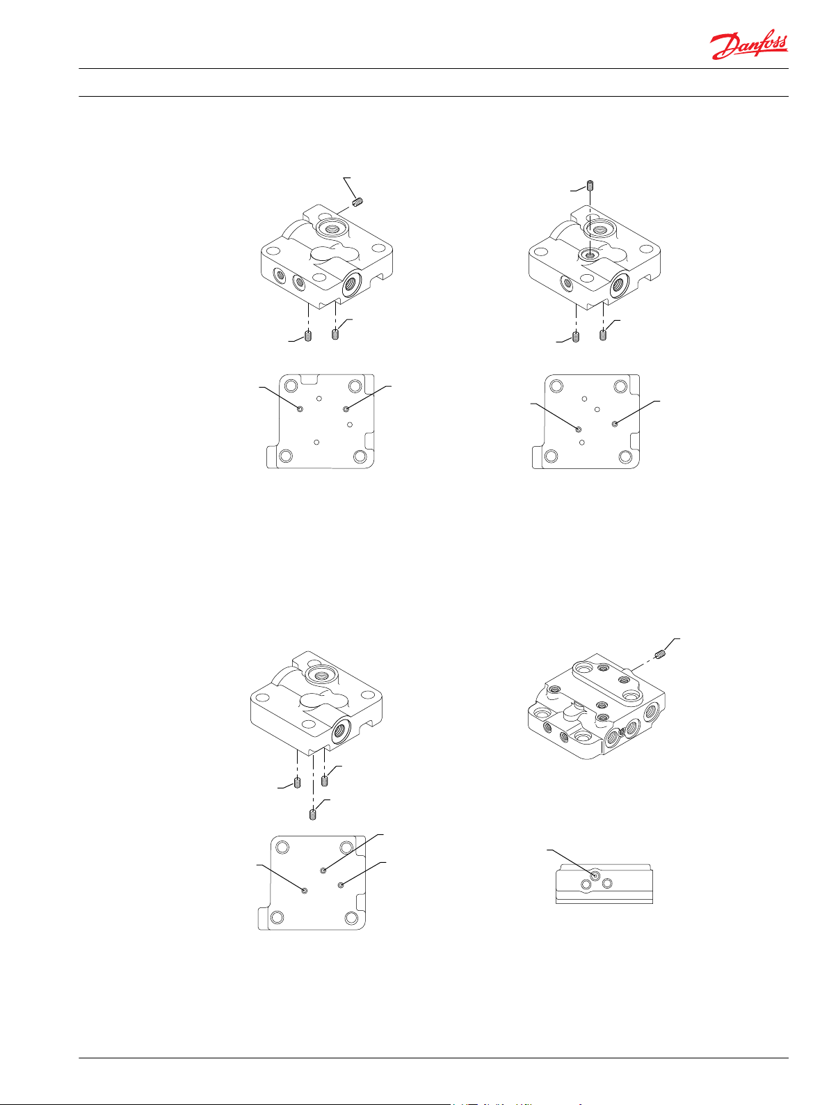
B* control codes E* and F* control codes
N* control codes
T* control codes
T3
T2
U5
T3
T2
U5
T3
T3
T2
T3
T2
U5
U5
U5
T3
Service Manual Series 51-1 Controls B1, B2, B7, E1, E2, E7, F1, F2, N1, T1, T2, T7, TA, TH, P7, P8
Required tools, gauge port and orifice locations
Orifice locations
11009443 • Rev BA • February 2015 9
Page 10

X1(M3)
M5
B
M4
L1
N
L2
A
P001 779E
n
min.
disp.
T2
T3
U5
Service Manual Series 51-1 Controls B1, B2, B7, E1, E2, E7, F1, F2, N1, T1, T2, T7, TA, TH, P7, P8
N1 two-position control
Functional Description
The N1 control consists of a ported housing that is mounted on the endcap over the piston end of the
servo piston.
The housing contains two external ports, designated M3 and M5. These ports serve as the control inputs.
There are three interface ports1 that connect to the rod and piston ends of the servo, and to the servo
supply port in the endcap. The servo supply connects to the output of the loop flushing spool so it
dispenses low loop pressure to the control regardless of motor direction.
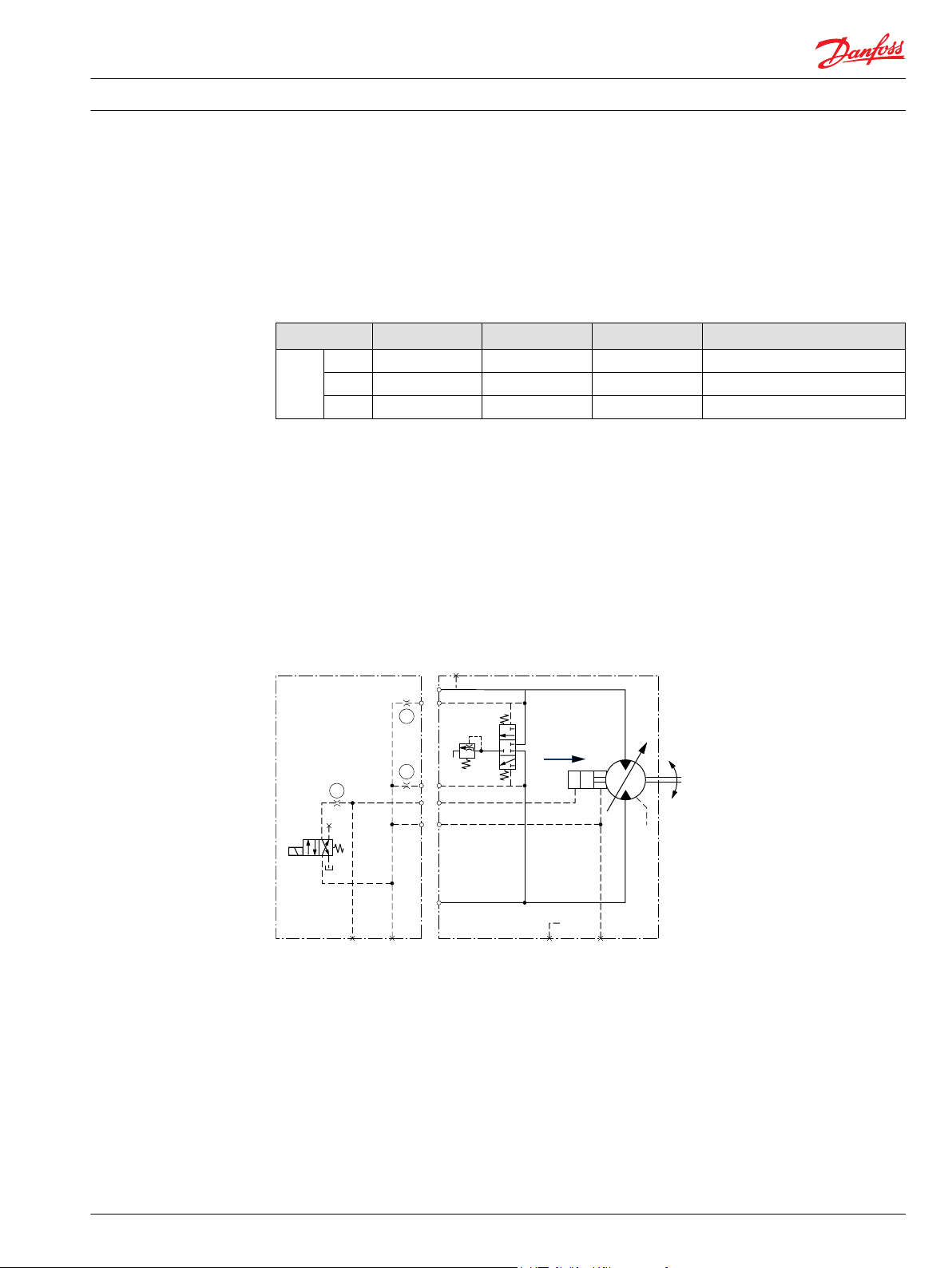
The control routes servo supply pressure through orifices U5 and T2 to the rod end of the servo piston.
This holds the motor at maximum displacement until pressure from an external source is applied at port
M3. This signal pressure then routes through orifice T3 to the piston end of the servo, shifting the motor
to minimum displacement. Typically 20 to 25 bar [290 to 360 psi] is necessary to shift the motor.
You may also install a plug in place of orifice U5, blocking the connection to servo supply. You can then
apply pressure from an external source at port M5 to shift the motor to maximum displacement.
Orifices T2 and T3 set the control response by limiting the flow to either end of the servo piston.
Schematic diagram
N1 control schematic diagram
Adjustments
This control requires no adjustments.
Minor repair
Disassembly
1. Thoroughly clean all external surfaces before disassembly. Mark components as necessary to ensure
you reassemble the unit correctly.
2. Remove the 4 screws (M16). Use an 8mm internal hex wrench.
1
Interface ports are those between the control and the endcap.
10 11009443 • Rev BA • February 2015
3. Remove the control housing (M1N*) from the endcap.
Page 11
M14
M14
M16
M12
M1N*
G42
G420
P101176
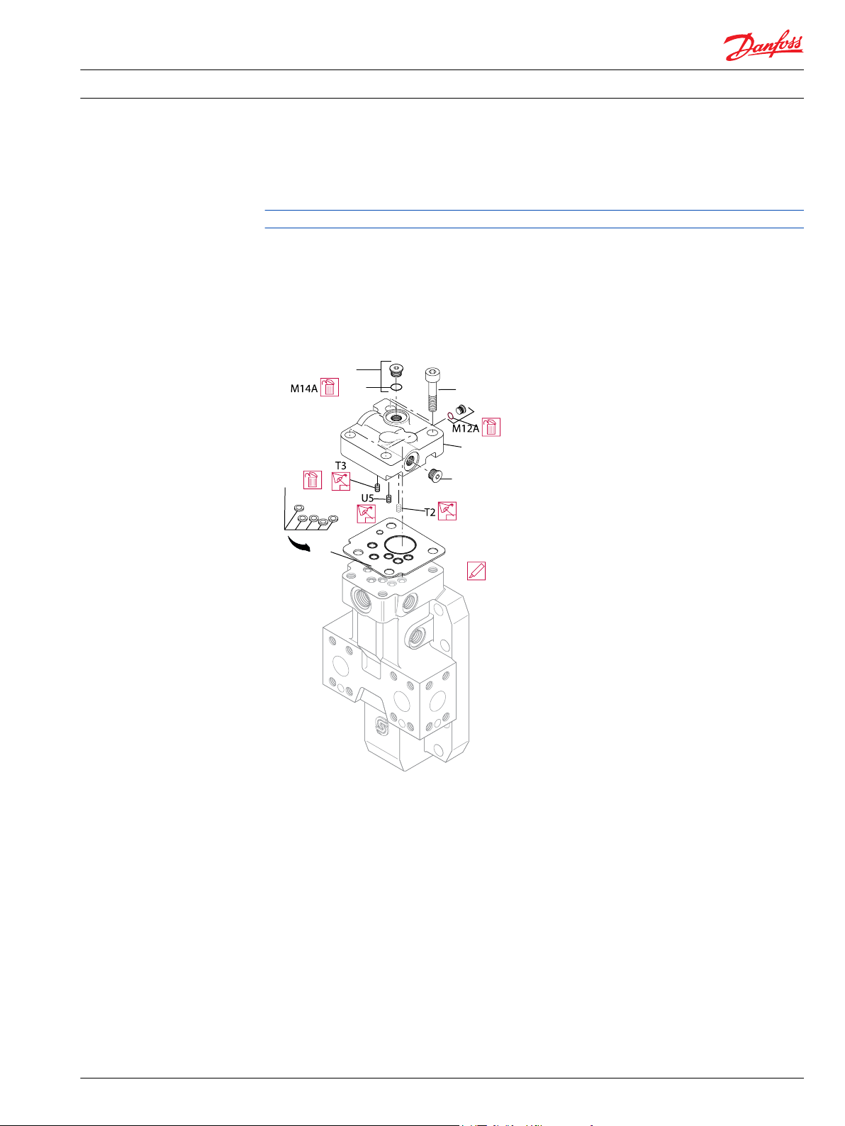
Service Manual
N1 two-position control
Series 51-1 Controls B1, B2, B7, E1, E2, E7, F1, F2, N1, T1, T2, T7, TA, TH, P7, P8
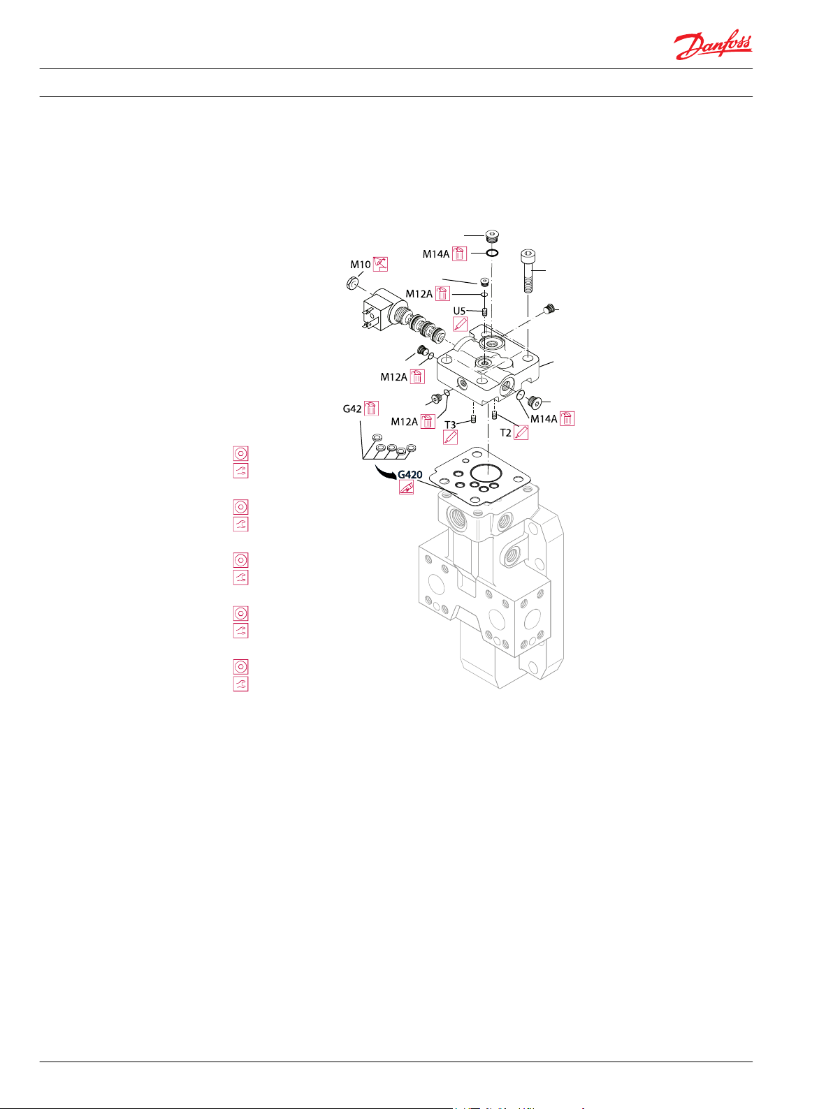
4. After ensuring you have the correct replacement parts, remove and discard the interface O-rings
(G42), or remove the control gasket (G420) from the endcap.
5. Using a 1/4-inch internal hex wrench remove plugs (M14) from the housing.
Fasteners are metric. Porting plugs are SAE.
6. Using a 1/8-inch internal hex wrench remove plug (M12) from the housing.
7. After ensuring you have the correct replacement parts, remove and discard O-rings (M12A and M14A)
from the plugs (M12 and M14).
8. If necessary, remove T2, T3, and U5 control orifices. Use a 3mm internal hex wrench. Tag the orifices
for reassembly.
N1 control exploded
Inspection
Clean and inspect all parts for damage. Check orifices and passages in control housing for foreign
material.
Assembly
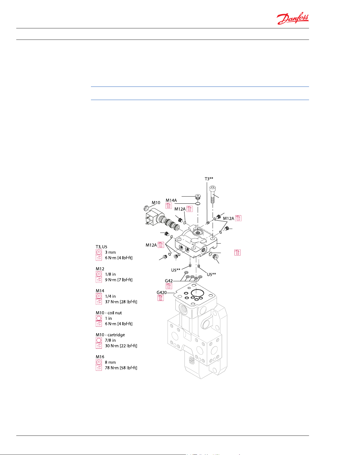
1. If removed, install control orifices T2, T3, and U5 to their proper location. Using a 3mm internal hex
wrench, torque the orifices to 6 N•m [4 lbf•ft].
2. Lubricate and install new O-rings on the housing plugs (M12). Using a 1/8-inch internal hex wrench,
torque them to 9 N•m [7 lbf•ft]
3. Lubricate and install new O-rings on the housing plugs (M14). Using a 1/4-inch internal hex wrench,
torque them to 37 N•m [28 lbf•ft].
4. Using clean petroleum jelly to retain them, install new interface O-rings (G42) or a new control gasket
(G420) on the endcap.
11009443 • Rev BA • February 2015 11
Page 12

M14A
M12A
M1N*
P106 491E
Service Manual Series 51-1 Controls B1, B2, B7, E1, E2, E7, F1, F2, N1, T1, T2, T7, TA, TH, P7, P8
N1 two-position control
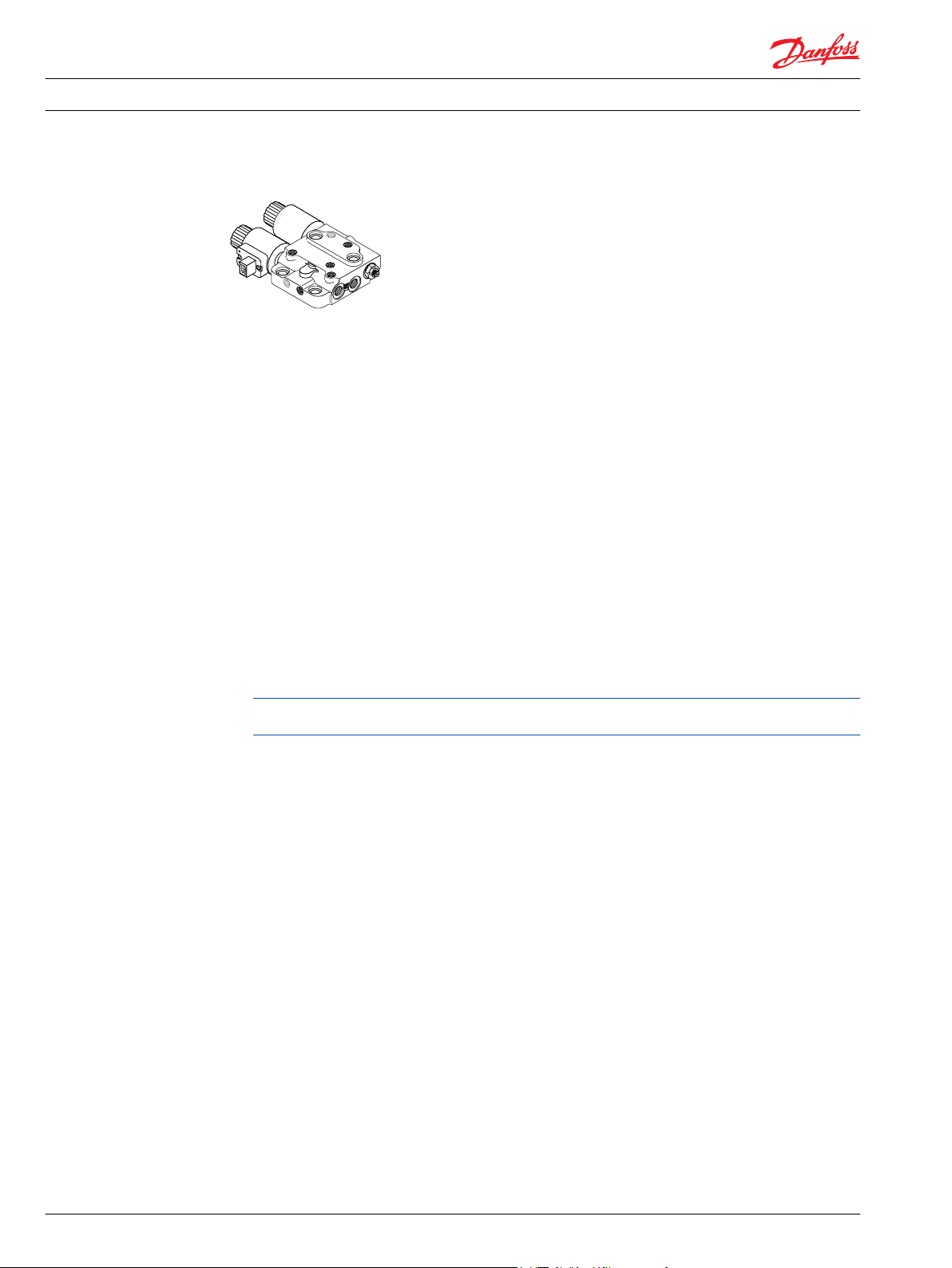
5. Install the control housing and retaining screws (M16) on the endcap. Using an 8mm internal hex
wrench torque the retaining screws to 78 N•m [58 lbf•ft].
N1 control assembly
12 11009443 • Rev BA • February 2015
Page 13

n
min.
disp.
T2
T3
M4
B
M3M5
L1
NL2
A
P001 780E
U5
Service Manual
Series 51-1 Controls B1, B2, B7, E1, E2, E7, F1, F2, N1, T1, T2, T7, TA, TH, P7, P8
E1, E2, E7, F1, F2 two-position controls
Functional description
The E* and F* controls consist of a ported housing that is mounted onto the endcap over the piston end
of the servo piston. The housing contains a solenoid operated four-way, two-position cartridge valve that
routes servo supply pressure to either the rod or piston end of the servo piston while draining the
opposite end. The coil and valve are common, but the housing changes between the E and F controls.
Orifices U5, T2, and T3 set the control response.
The housing contains two external ports, designated M3 and M5. These ports, along with port M4 in the
endcap, serve as diagnostic ports for troubleshooting control performance. Port M4 connects to the rod
end of the servo piston (maximum angle), port M3 connects to the piston end of the servo piston
(minimum angle), and port M5 connects to servo supply pressure (downstream of orifice U5).
You may also install a plug in place of orifice U5 if you desire to use pressure from an external source at
port M5 to serve as supply to the solenoid valve.
This table shows control logic, input voltage, and connector type for each control type.
Control requirements
Type Sol. on Sol. off Volts Connector
E 1 min. max. 12v DIN 46350
2 min. max. 24v DIN 46350
7 min. max. 12v Jet Jr. Timer
F 1 max. min. 12v DIN 46350
2 max. min. 24v DIN 46350
Schematic diagrams
Schematic diagram of E* controls
With E* controls, the motor defaults to maximum displacement, shifting to minimum when the
•
solenoid is energized.
11009443 • Rev BA • February 2015 13
Page 14

n
min.
disp.
T2
T3
M4
B
M3M5
L1
NL2
A
P001 867E
U5
Service Manual
Series 51-1 Controls B1, B2, B7, E1, E2, E7, F1, F2, N1, T1, T2, T7, TA, TH, P7, P8
E1, E2, E7, F1, F2 two-position controls
Schematic diagram of F* controls
With F* controls, the motor defaults to minimum displacement, shifting to maximum when the
•
solenoid is energized.
Adjustments
These controls require no adjustments.
Minor repair
Disassembly
1. Thoroughly clean all external surfaces before disassembly.
2. Using a 3/4-inch wrench remove the coil nut from the solenoid valve stem (M10).
3. Slide the coil off of the solenoid valve stem (M10).
4. Using a 7/8-inch wrench remove the solenoid valve (M10) from the control housing.
5. Remove and discard the O-rings and backup rings from the cartridge.
Always ensure you have the correct replacement parts (O-rings/seals) before discarding the used
ones.
6. Using a 8mm internal hex wrench remove the 4 screws (M16) .
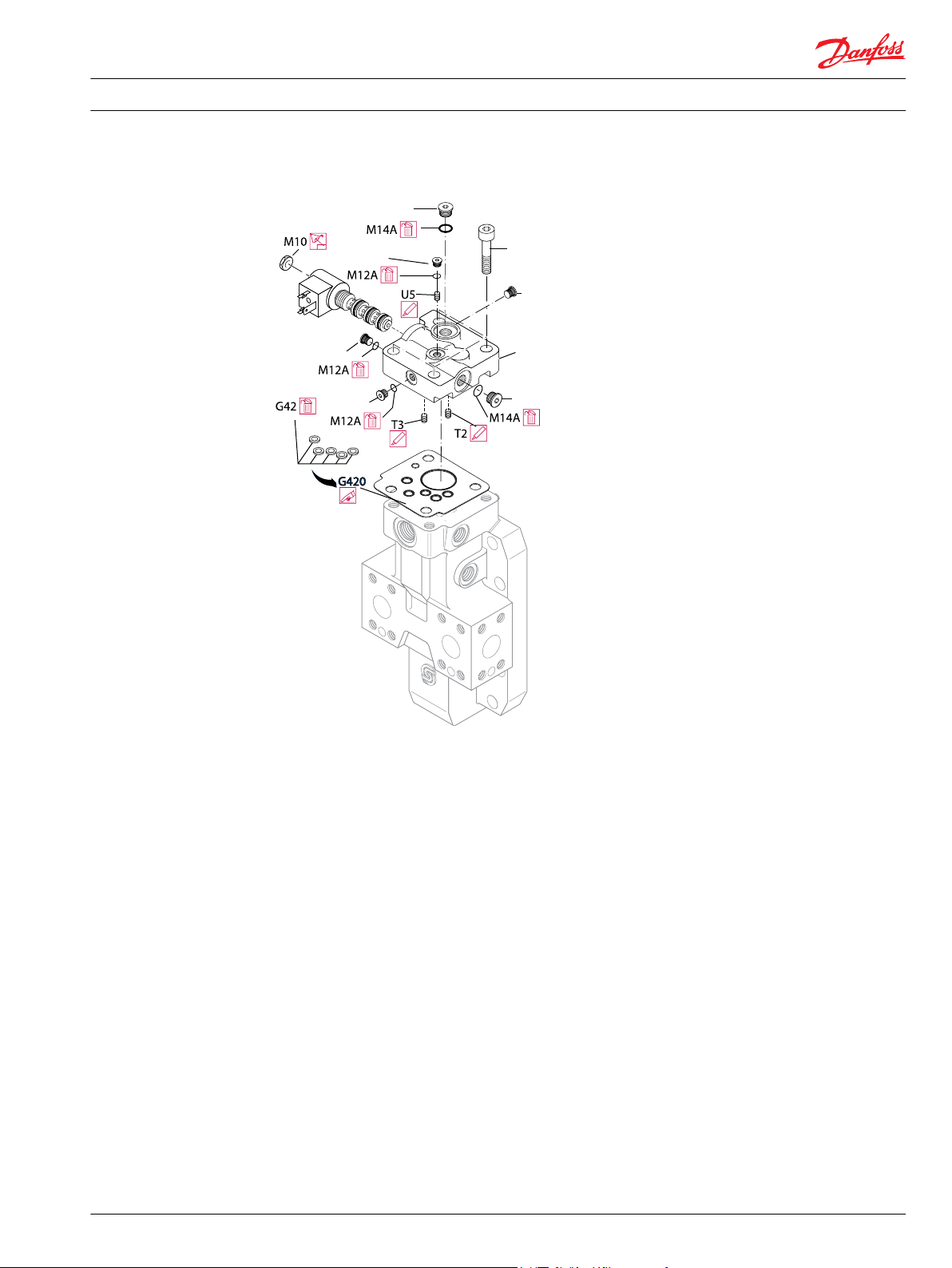
7. Remove the control housing (M1E* / M1F*) from the endcap.
8. Remove and discard the O-rings (G42) or the control gasket (G420) from the endcap.
9. Using a 1/8-inch internal hex wrench remove all plugs (M12) from the control housing.
10. Using a 1/4-inch internal hex wrench remove all plugs (M14) from the control housing.
11. Remove and discard the O-rings (M12A, M14A) from the plugs.
12. If necessary, remove orifices (T2, T3, and U5) using a 3mm internal hex wrench. Tag each orifice for
reassembly.
14 11009443 • Rev BA • February 2015
Page 15
M14
M12
M16
M12
M12
M12
M1E*
M1F*
M14
P101175
Service Manual
Series 51-1 Controls B1, B2, B7, E1, E2, E7, F1, F2, N1, T1, T2, T7, TA, TH, P7, P8
E1, E2, E7, F1, F2 two-position controls
E*, F* control disassembly
Inspection
Clean and inspect all parts for damage. Check orifices and passages in control housing for foreign
material.
Assembly
1. If removed, install orifices (T2, T3, and U5) in to their proper location using a 3mm internal hex
wrench. Torque the orifices to 6 N•m [4 lbf•ft]
2. Lubricate and install new O-rings (M14A) on to the plugs (M14). Using a 1/4-inch internal hex wrench
torque the plugs (M14) to 37 N•m [28 lbf•ft]
3. Lubricate and install new O-rings (M12A) on to the plugs (M12). Using a 1/8-inch internal hex wrench
torque the plugs to 9 N•m [7 lbf•ft].
4. Using clean petroleum jelly to retain them, install new interface O-rings (G42) or new control gasket
(G420) on the endcap.
5. Install the control housing (M1E*/ M1F*) to the endcap.
6. Install the retaining screws (M16). Using an 8mm internal hex wrench, torque the screws to 78 N•m
[58 lbf•ft].
7. Lubricate and install new O-rings and backup rings onto the solenoid cartridge.
8. Using a 7/8-inch wrench install the solenoid cartridge into the control housing. Torque the cartridge
to 30 N•m [22 lbf•ft]. Do not overtorque.
9. Slide the solenoid coil over the valve stem.
11009443 • Rev BA • February 2015 15
Page 16
M14
M12
M16
M12
M12
M12
M1E*
M1F*
M14
P101175b
T2, T3, U5
3 mm
6 N•m [4 lbf•ft]
M12
1/8 in
9 N•m [7 lbf•ft]
M14
1/4 in
37 N•m [28 lbf•ft]
M10 - coil nut
1 in
6 N•m [4 lbf•ft]
M10 - cartridge
7/8 in
30 N•m [22 lbf•ft]
Service Manual Series 51-1 Controls B1, B2, B7, E1, E2, E7, F1, F2, N1, T1, T2, T7, TA, TH, P7, P8
E1, E2, E7, F1, F2 two-position controls
10. Install the solenoid coil nut. Using a 1 inch wrench, torque the coil nut to 6 N•m [4 lbf•ft]. Do not
overtorque.
E*/F* control assembly
16 11009443 • Rev BA • February 2015
Page 17
B
L1 M4
M5M3
A
L2
U5
U5
T3
min.
disp.
P101192E
Service Manual
Series 51-1 Controls B1, B2, B7, E1, E2, E7, F1, F2, N1, T1, T2, T7, TA, TH, P7, P8
B1, B2, B7 two-position controls
Functional description
The B* controls consist of a ported housing mounted on the endcap over the piston end of the servo
piston. The housing contains a four-way, two-position, solenoid-operated cartridge valve. The table
shows control logic, input voltage, and connector for each control:
Control requirements
Type SOL on SOL off Volts Connector
B 1 min. max. 12v DIN 46350
Internal porting in the control housing connects system A and system B ports together through two
orifices (U5). This connection creates a minimal cross port flow. It provides a source of servo supply
pressure that is about one-half of system pressure. The housing is ported internally to route this servo
supply pressure continually to the rod end of the servo.
The cartridge valve routes servo supply pressure to the piston end of the servo piston through an orifice
(T3) when operated by an electrical signal. This allows the motor to shift to minimum displacement.
When the valve is not operating, the piston end of the servo piston is drained to motor case. This permits
the motor to default to maximum displacement.
2 min. max. 24v DIN 46350
7 min. max. 12v Jet Jr. Timer
Adjustments
Minor repair
Schematic diagram
four-way, 2-position, solenoid operated cartridge valve
These controls require no adjustments.
Disassembly
1. Thoroughly clean all external surfaces before disassembly.
2. Using a 1 inch wrench remove the coil nut from the solenoid valve (M10).
11009443 • Rev BA • February 2015 17
Page 18
M12
M12
M12
M12
M12
M12
M14
M14
M16
M1B*
P101191a2
M14A
Service Manual
Series 51-1 Controls B1, B2, B7, E1, E2, E7, F1, F2, N1, T1, T2, T7, TA, TH, P7, P8
B1, B2, B7 two-position controls
3. Slide the coil from the solenoid valve stem (M10).
4. Using a 7/8-inch wrench remove the valve cartridge from the control housing.
5. Remove and discard the O-rings and back-up rings from the cartridge.
6. Remove the 4 screws (M16) retaining the control housing to the endcap.
7. Lift the control housing (M1B*) off of the endcap.
8. Remove and discard the O-rings (G42) or the control gasket (G420) from the endcap.
9. Using a 1/8-inch internal hex wrench remove plugs (M12) from the control housing.
10. Remove and discard the O-rings (M12A).
11. Using a 1/4-inch internal hex wrench remove plugs (M14) from the control housing.
12. Remove and discard the O-rings (M14A).
13. Using a 3mm internal hex wrench remove orifices (T3 and U5). Tag the orifices for reassembly.
B* control disassembly
Always ensure you have the correct replacement parts (O-rings/seals) before discarding the used
ones.
Inspection
Clean and inspect all parts for damage. Check orifices and passages in control housing for foreign
material.
18 11009443 • Rev BA • February 2015
Page 19

M12
M12
M12
M12
M12
M12
M14
M14
M16
M1B*
P101191a2
M14A
Service Manual Series 51-1 Controls B1, B2, B7, E1, E2, E7, F1, F2, N1, T1, T2, T7, TA, TH, P7, P8
B1, B2, B7 two-position controls
Assembly
1. Install orifices (T3 and U5) in to their proper location. Using a 3mm internal hex wrench torque the
orifices to 6 N•m [4 lbf•ft].
2. Install new O-rings (M12A) on the plugs (M12). Install the plugs using a 1/8-inch internal hex wrench.
Torque to 9 N•m [7 lbf•ft].
3. Install new O-rings (M14A) on the plugs (M14). Install the plugs using a 1/4-inch internal hex wrench.
Torque to 37 N•m [28 lbf•ft].
4. Using clean petroleum jelly to retain them, install new interface O-rings (G42) or new control gasket
(G420) on the endcap.
5. Install the control housing on the endcap.
6. Using an 8mm internal hex wrench, install the retaining screws (M16). Torque to 78 N•m [58 lbf•ft].
7. Lubricate the solenoid valve cartridge (M10) with clean hydraulic oil.
8. Lubricate and install new O-rings and backup rings on the solenoid cartridge (M10).
9. Install the cartridge into the control housing. Using a 7/8-inch wrench, torque the cartridge to 35 N•m
[35 lbf•ft]. Do not overtorque.
10. Slide the solenoid coil over the valve stem.
11. Install the solenoid coil nut. Using a 3/4-inch, torque, to 6 N•m [22 lbf•in]. Do not overtorque.
B* control sassembly
11009443 • Rev BA • February 2015 19
Page 20

Service Manual
Series 51-1 Controls B1, B2, B7, E1, E2, E7, F1, F2, N1, T1, T2, T7, TA, TH, P7, P8
T1, T2, T7, TA, TH Pressure Compensator (PC) controls
Functional Description
Overview
Pressure Compensator (PC) controls operate by routing system (high) pressure to both ends of the servo
piston. Because the piston end of the servo piston has greater area, this causes the motor to shift to
minimum displacement by default. When system pressure reaches the PC setpoint, the control drains the
piston end of the servo piston allowing the motor to shift toward maximum displacement. The control
modulates the displacement position of the motor, keeping system pressure at or below the PC set point.
When the motor reaches maximum displacement, system pressure may rise above the PC set point until
the pump pressure limiter or system relief valve begins to operate
Option TA
TA option PC controls operate strictly as described above, with the option of several brake pressure
defeat configurations that we explain later.
TA control cross section
Option TH
TH option PC controls operate as described above except a piston is installed to operate the PC control
spool and shift the motor to maximum displacement when a hydraulic-pressure signal is applied. 10 to 35
bar [145 to 507 psi] applied at port X1 overrides the PC function and shifts the motor to maximum
displacement. There is a second option of several brake pressure defeat configurations. We explain this
option later.
20 11009443 • Rev BA • February 2015
Page 21

Service Manual
Series 51-1 Controls B1, B2, B7, E1, E2, E7, F1, F2, N1, T1, T2, T7, TA, TH, P7, P8
T1, T2, T7, TA, TH Pressure Compensator (PC) controls
TH control cross section
Option T1T2/T7
T1/T2/T7 option PC controls operate as described above with an additional feature. A solenoid is
installed to operate the PC control spool and shift the motor to maximum displacement when an electric
signal is applied. The solenoid is available in three configurations: 12V (T1) or 24V (T2) with DIN 43650
connector, and 12V with Jet Jr.™ timer connector (T7) with integral zener diode transient voltage
suppressor. There is a second option of several brake pressure defeat configurations. We explain this
option later.
T1/T2/T7 cross section
Brake pressure defeat
Brake Pressure Defeat (BPD) options are available that abort the PC control operation during dynamic
breaking.
Option D1/D2/D7
The BPD feature is electrically operated by a solenoid. The electric signal applied to the solenoid allows
PC functions to operate only when system port A has high pressure. This defeats PC operation when
11009443 • Rev BA • February 2015 21
Page 22

Service Manual
Series 51-1 Controls B1, B2, B7, E1, E2, E7, F1, F2, N1, T1, T2, T7, TA, TH, P7, P8
T1, T2, T7, TA, TH Pressure Compensator (PC) controls
system port B is high. When no signal is applied to the solenoid, PC functions operate only when system
port B has high pressure. This defeats PC operation when system port A is high.
BPD option D1/D2/D7 cross section
The solenoid is available in three configurations. The configurations are: 12V (D1) or 24V (D2) with DIN
43650 connector, and 12V with Jet Jr.™ timer connector (D7) with integral zener diode transient voltage
suppressor.
Option CA
An external hydraulic signal at ports XA or XB operates the BPD feature. Pressure applied at port XA
allows PC functions to operate only when system port A has high pressure, defeating PC operation when
system port B is high. Pressure applied at port XB allows PC functions to operate only when system port
B has high pressure, defeating PC operation when system port A is high.
BPD option CA cross section
Option C2
No BPD features are used. PC operation is allowed in either direction. The BPD spool resolves high
pressure and routes it to the PC spool.
22 11009443 • Rev BA • February 2015
Page 23

min.
disp.
M4L1
B
A
L2
XA
XB
M3
T3
M3
T3
M3
T3
M3
T3
Plug loc. - R5
Plug loc. - L5
(R5 shown)
U5
TA C2
TA CA
TA D1/D2/D7
TA RS/LS
Service Manual
Series 51-1 Controls B1, B2, B7, E1, E2, E7, F1, F2, N1, T1, T2, T7, TA, TH, P7, P8
T1, T2, T7, TA, TH Pressure Compensator (PC) controls
BPD option C2cross section
Option R5
No BPD features are used. PC operation is allowed only when system port A has high pressure. No BPD
spool is used. System B interface port is plugged.
Option L5
No BPD features are used. PC operation is allowed only when system port B has high pressure. No BPD
spool is used. System A interface port is plugged.
BPD option R5/L5 cross section
Schematic diagrams - TA
Schematics These schematic diagrams illustrate the T1, T2, T7, TA, and TH pressure compensator (PC) controls.
11009443 • Rev BA • February 2015 23
Page 24

min.
displ.
M4L1
B
A
L2
T1/2/7 D1/D2/D7
M3
T3
T1/2/7 R5/L5
M3
T3
Plug loc. - R5
Plug loc. - L5
(R5 shown )
T1/2/7 CA
XA
XB
M3
T3
T1/2/7 C2
M3
T3
U5
min.
displ.
M4L1
B
A
L2
X1
TH C2
M3
T3
X1
TH CA
XA
XB
M3
T3
TH D1/D2/D7
M3
T3
X1
TH R5/L5
M3X1
T3
Plug loc. - R5
Plug loc. - L5
(R5 shown)
U5
W
Service Manual
Series 51-1 Controls B1, B2, B7, E1, E2, E7, F1, F2, N1, T1, T2, T7, TA, TH, P7, P8
T1, T2, T7, TA, TH Pressure Compensator (PC) controls
Schematic diagrams - T1/T2/T7
Schematic diagrams - TH
Adjustment
Warning
Do not perform this procedure unless the machine can be safely operated while loading the motor shaft
as described. If necessary, remove the motor from the application and perform this procedure in an
appropriate test stand.
PC start pressure
The pressure compensator start pressure setting is adjustable in a range from 110 to 370 bar [1595 to
5366 psi]. To measure the start pressure setting:
apply the vehicle’s brakes to lock the motor shaft from turning
•
or
add an extreme load to the work function of the machine.
•
To check or reset the pressure compensator setting on a vehicle:
1. Install a 600 bar [10,000 psi] gauge at port M4 to monitor pressure at the rod end (maximum
displacement) of the servo piston.
Due to the control’s configuration the pressure at M4 will equal the system pressure.
2. Install a 600 bar [10,000 psi] gauge at port M3 to monitor pressure at the piston end (minimum
displacement) of the servo piston.
24 11009443 • Rev BA • February 2015
Page 25

M3
M4
P101244b
Service Manual
Series 51-1 Controls B1, B2, B7, E1, E2, E7, F1, F2, N1, T1, T2, T7, TA, TH, P7, P8
T1, T2, T7, TA, TH Pressure Compensator (PC) controls
3. Start the prime mover and operate at normal speed.
4. Stroke pump very slowly to gradually increase system pressure to the PC setting pressure, or:
a) lower the pump’s multifunction valve (Series 90) or HPRV (H1) below the PC setting
b) stroke the pump to approximately 1/4 displacement
c) adjust the multifunction valve (Series 90) or HPRV (H1) to slowly increase system pressure to the
PC setting pressure.
5. Watch the gauge at port M3. When pressure in M3 begins to decrease, note the pressure at port M4.
This is the PC setting.
If you don’t get the correct pressure setting, repeat step 4 using a different option. The result
depends on the application.
PC setting
To check or reset the pressure compensator setting on a test stand:
1. Monitor system flow.
2. Increase the system pressure until flow begins to increase. System gauge pressure at this point is the
PC setting.
To adjust the pressure compensator setting:
1. Use a 10mm hex wrench to loosen the seal locknut.
2. Using a 3mm internal hex wrench, turn the PC adjusting screw clockwise to increase the pressure
setting, counter-clockwise to decrease the setting.
The pressure compensator setting changes at a rate of approximately 70 bar [800 psi] per turn.
3. Using a 10mm hex wrench to hold the adjustment screw in place torque the seal locknut to 52 N•m
[38 lbf•ft].
4. Recheck the pressure compensator setting and readjust the as necessary.
11009443 • Rev BA • February 2015 25
Page 26
Pressure Compensator
adjusting screw
P101244a2
Service Manual
Series 51-1 Controls B1, B2, B7, E1, E2, E7, F1, F2, N1, T1, T2, T7, TA, TH, P7, P8
T1, T2, T7, TA, TH Pressure Compensator (PC) controls
PC adjusting screw
After testing and adjustment:
1. Readjust the pump multifunction valve (Series 90) or HPRV (H1) to its proper setting if it was changed.
2. Shut down the prime mover.
3. Remove the gauges.
4. Return the system to its normal operating configuration.
Minor repair
Control housing
1. Thoroughly clean all external surfaces before disassembly.
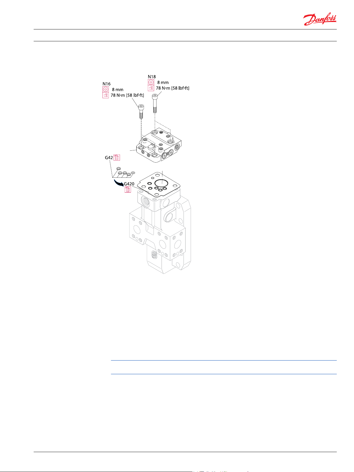
2. Using an 8mm internal hex wrench remove the 4 screws (N16 and N18) retaining the control housing
to the endcap.
3. Lift the control housing (N10) from the endcap.
4. Remove the interface O-rings (G42) or the gasket (G420). Remove and discard the O-rings or gasket.
Always ensure you have the correct replacement parts (O-rings/seals) before discarding the used
ones.
5. Make necessary repairs., see pages 28-46 for options.
6. Using clean petroleum jelly to retain them during assembly, install the new interface O-rings (G42) or
the gasket (G420) to the endcap, .
7. Install the control housing (N10) to the endcap.
8. Align the holes and install the four retaining screws (N16 and N18).
9. Using an 8mm internal hex wrench torque the four retaining screws (N16 and N18) to 78 N•m [58
lbf•ft].
26 11009443 • Rev BA • February 2015
Page 27
N10
P101186_a
Service Manual
Series 51-1 Controls B1, B2, B7, E1, E2, E7, F1, F2, N1, T1, T2, T7, TA, TH, P7, P8
T1, T2, T7, TA, TH Pressure Compensator (PC) controls
Control housing T*
TA option components
Disassembly
1. Thoroughly clean all external surfaces before disassembly.
2. Using an 11/16 inch wrench remove, the pressure compensator adjustment assembly (M22).
3. Remove the pressure compensator spring (M23).
4. Remove the stepped spool (M24).
Always ensure you have the correct replacement parts (O-rings/seals) before discarding the used
ones.
5. Remove the stepped spool (M24).
6. Using a 1/4 inch internal hex wrench, remove plug (M1TA). Remove and discard O-ring (M1TAA).
7. Refer to Servo-supply options for procedures pertaining to your particular servo-supply option.
11009443 • Rev BA • February 2015 27
Page 28

P101186_b
1/4 in
1/8 in
Service Manual
Series 51-1 Controls B1, B2, B7, E1, E2, E7, F1, F2, N1, T1, T2, T7, TA, TH, P7, P8
T1, T2, T7, TA, TH Pressure Compensator (PC) controls
TA components
Inspection
Clean and inspect all components for damage. Replace as necessary
Assembly
1. Lubricate and install new O-ring (M1TAA) on plug (M1TA). Install plug using a 1/4 inch internal hex
wrench. Torque to 9 N•m [7 lbf•ft].
2. Lubricate and install new O-ring (M26A) on plug (M26). Install plug using a 1/8 inch internal hex
wrench. Torque to 37 N•m [28 lbf•ft].
3. Lubricate and install the stepped spool (M24) into the control housing bore.
4. Install the spring (M23) into the control housing bore.
5. Lubricate and install new O-rings on the pressure compensator adjustment assembly (M22). Using an
11/16 inch hex wrench, install and torque the pressure compensator adjustment assembly to 25 N•m
[16 lbf•ft].
TH option components
Disassembly
1. Thoroughly clean all external surfaces before disassembly.
2. Using an 11/16 inch wrench remove, the pressure compensator adjustment assembly (M22).
3. Remove the pressure compensator spring (M23).
4. Remove the stepped spool (M24).
5. Using a 1/4 inch internal hex wrench, remove plug (M1TA). Remove and discard O-ring (M1TAA).
Always ensure you have the correct replacement parts (O-rings/seals) before discarding the used
ones.
6. Using a 1/8 inch internal hex wrench, remove plug (M26). Remove and discard O-ring (M26A).
7. Remove the assist piston (M25) from the housing bore.
8. Refer to Servo-supply options for procedures pertaining to your particular servo-supply option.
28 11009443 • Rev BA • February 2015
Page 29

1/4 in
1/8 in
M25
P106 441E
M22
h 11/16 in. hex wrench
t 25 N•m [16 lbf•ft]
Service Manual
Series 51-1 Controls B1, B2, B7, E1, E2, E7, F1, F2, N1, T1, T2, T7, TA, TH, P7, P8
T1, T2, T7, TA, TH Pressure Compensator (PC) controls
TA components
Inspection
Clean and inspect all components for damage. Replace as necessary
Assembly
1. Install assist piston (M25) to the housing bore.
2. Lubricate and install new O-ring (M1TAA) on plug (M1TA). Install plug using a 1/4 inch internal hex
wrench. Torque to 9 N•m [7 lbf•ft].
3. Lubricate and install new O-ring (M26A) on plug (M26). Install plug with retaining pin using a 1/8 inch
internal hex wrench. Ensure pin retains assist piston in bore. Torque to 37 N•m [28 lbf•ft].
4. Lubricate and install the stepped spool (M24) into the control housing bore.
5. Install the spring (M23) into the control housing bore.
6. Lubricate and install new O-rings on the pressure compensator adjustment assembly (M22). Using an
11/16 inch hex wrench, install and torque the pressure compensator adjustment assembly to 25 N•m
[16 lbf•ft].
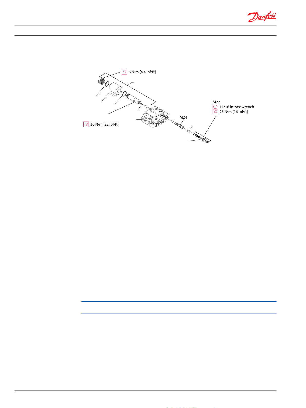
T1, T2, T7 option components
Disassembly
1. Thoroughly clean all external surfaces before disassembly.
2. Using an 11/16 inch wrench remove the PC adjustment assembly (M22). Remove and discard the O-
rings.
3. Remove the pressure compensator spring (M23).
4. Remove the stepped spool (M24).
5. Remove the plastic coil nut from the solenoid valve (M1) by hand.
6. Remove the first O-ring. Slide the coil off the cartridge. Remove the second O-ring. Remove and
discard the O-rings.
7. Using a thin 3/4-inch wrench remove the cartridge from the control housing (N10). Remove and
discard the O-ring (M1T*A).
8. If it remains in the housing, remove the pushrod.
11009443 • Rev BA • February 2015 29
Page 30
M1
M1A
N10
M23
O-ring 1
O-ring 2
Solenoid coil
Plastic nut
Cartridge
3/4 in. flats
M22A
P101187a
Service Manual
Series 51-1 Controls B1, B2, B7, E1, E2, E7, F1, F2, N1, T1, T2, T7, TA, TH, P7, P8
T1, T2, T7, TA, TH Pressure Compensator (PC) controls
T1/2/7 components
Inspection
Thoroughly clean and inspect all components for damage or foreign material. Replace damaged parts as
necessary.
Assembly
1. Install the stepped spool (M24) to the housing bore.
2. Install the spring (M23).
3. Lubricate and install new O-rings on the PC adjustment assembly (M22). Using an 11/16 inch hex
wrench, install the PC adjustment assembly to the housing. Torque to 25 N•m [16 lbf•ft].
4. Slide the pushrod into the cartridge. Install the cartridge to the housing. Using a 3/4 inch hex wrench
on the flats, torque the cartridge to 30 N•m [22 lbf•ft].
5. Lubricate and install a new O-ring onto the cartridge. Install the solenoid coil. Install the second O-
ring. Install the plastic nut and torque by hand to 6 N•m [4.4 lbf•ft].
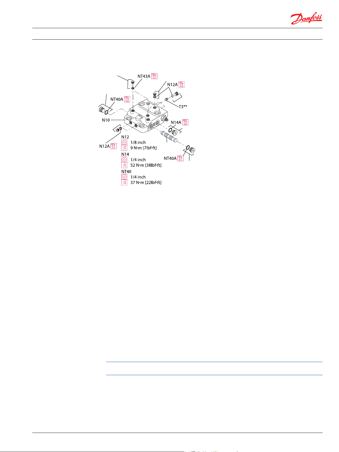
Servo/PC supply option CA (with hydraulic signal)
Disassembly
1. Thoroughly clean all external surfaces before disassembly.
2. Using a 1/8 inch internal hex wrench, remove seven plugs (N12) from the control housing (N10).
Remove and discard the O-rings (N12A).
3. Using a 1/4 inch internal hex wrench remove the plug (N14) from the control housing. Remove and
discard the O-ring (N14A).
Always ensure you have the correct replacement parts (O-rings/seals) before discarding the used
ones.
4. Using a 3mm internal hex wrench, remove the orifice (T3). Note the location for reassembly.
5. Using a 1/4 inch internal hex wrench or 11/16 inch hex wrench, remove the plugs/fittings (NT40) from
ports XA and XB in the control housing. Remove and discard the O-rings (NT40A).
6. Using a 1/8 inch internal hex wrench, remove the two pin-plugs (NT43) from the control housing.
30 11009443 • Rev BA • February 2015
Remove and discard the O-rings (NT43A).
7. Slide the BPD spool (NT42) from the housing bore.
Page 31
NT43
NT40
NT42
NT40
N12
N14
N12
N12
P101188_x
Service Manual
Series 51-1 Controls B1, B2, B7, E1, E2, E7, F1, F2, N1, T1, T2, T7, TA, TH, P7, P8
T1, T2, T7, TA, TH Pressure Compensator (PC) controls
CA servo supply option components
Inspection
Thoroughly clean and inspect all components for damage or foreign material. Replace damaged parts as
necessary.
Assembly
1. Using clean hydraulic oil, lubricate the BPD shuttle spool (NT42) and slide into the housing bore.
2. Lubricate and install new O-rings (NT43A) on to pin-plugs (NT43). Using a 1/8-inch internal hex
wrench, install the pin-plugs into the housing. Torque to 9 N•m [7 lbf• ft].
3. Using a 3mm internal hex wrench, install the T3 orifice. Torque to 6 N•m [4 lbf•ft].
4. Lubricate and install new O-rings to plugs/fittings (NT40). Install plugs/fittings to ports XA and XB.
Using a 1/4 inch internal hex wrench or 11/16 inch hex wrench, torque the plugs/fittings 37 N•m [28
lbf•ft].
5. Lubricate and install new O-rings to seven plugs (N12). Using a 1/8 inch internal hex wrench, install
and torque the plugs to 9 N•m [7 lbf•ft].
6. Lubricate and install new O-ring to plug (N14). Using a 1/4 inch internal hex wrench, install and
torque the plugs to 52 N•m [38 lbf•ft].
Servo/PC supply option C2 (without external signal)
1. Thoroughly clean all external surfaces before disassembly.
2. Using a 1/8 inch internal hex wrench, remove seven plugs (N12). Remove and discard the O-rings
(N12A).
3. Using a 1/4 inch internal hex wrench, remove the plug (N14). Remove and discard the O-ring (N14A).
Always ensure you have the correct replacement parts (O-rings/seals) before discarding the used
ones.
4. Using a 1/4 inch internal hex wrench, remove two plugs (NT40) from ports XA and XB. Remove and
discard the O-rings (NT40A).
5. Using a 1/8 inch internal hex wrench, remove two plugs (NT43). Remove and discard the O-rings
(NT43A).
6. Using a 3mm internal hex wrench, remove orifice (T3). Note the location for reassembly.
7. Using a 3mm internal hex wrench, remove two orifices (U5). Note the location for reassembly.
8. Remove the BPD spool (NT42) from the housing bore.
11009443 • Rev BA • February 2015 31
Page 32

NT43
NT40
NT42
NT40
N12
N14
N12
N12
P101188_y
Service Manual
Series 51-1 Controls B1, B2, B7, E1, E2, E7, F1, F2, N1, T1, T2, T7, TA, TH, P7, P8
T1, T2, T7, TA, TH Pressure Compensator (PC) controls
C2 Option components
Inspection
Thoroughly clean and inspect all components for damage or foreign material. Replace damaged parts as
necessary.
Assembly
1. Lubricate and install the BPD shuttle spool (NT42) into the housing bore.
2. Lubricate and install new O-rings (NT43A) on plugs (NT43). Using a 1/8 inch internal hex wrench,
install and torque the plugs to 9 N•m [7 lbf• ft].
3. Lubricate and install new O-rings (NT40A) on plugs (NT40). Using a 1/4 inch internal hex wrench,
install and torque the plugs to 37 N•m [22 lbf• ft].
4. Using a 3mm internal hex wrench, install orifice (T3). Torque to 6 N•m [4 lbf•ft].
5. Using a 3mm internal hex wrench, install two orifices (U5). Torque to 6 N•m [4 lbf•ft].
6. Lubricate and install new O-rings(N12A) on seven plugs (N12). Using a 1/8-inch internal hex wrench,
install and torque the plugs to 9 N•m [7 lbf• ft].
7. Lubricate and install new O-ring (N14A) on plug (N14). Using a 1/4 inch internal hex wrench, install
and torque the plug to 52 N•m [38 lbf• ft].
Servo/PC supply options D1/D2/D7
Disassembly
1. Thoroughly clean all external surfaces before disassembly.
32 11009443 • Rev BA • February 2015
Page 33

N10
NT42
NT40
NTD*
NTD*A
N12
N12
N14
N14A
NT43
Solenoid coil
Plastic nut
Cartridge
N12
P106 448E
N41
N12A
N12A
Service Manual
Series 51-1 Controls B1, B2, B7, E1, E2, E7, F1, F2, N1, T1, T2, T7, TA, TH, P7, P8
T1, T2, T7, TA, TH Pressure Compensator (PC) controls
2. Using a 1/8 inch internal hex wrench, remove seven plugs (N12). Remove and discard the O-rings
(N12A).
D1/D2/D7 components
3. Using a 1/4 inch internal hex wrench, remove the plug (N14). Remove and discard the O-ring (N14A).
4. Using a 1/4 inch internal hex wrench, remove plug (NT40) from port XB. Remove and discard the O-
ring (NT40A).
5. Using a 1/8 inch internal hex wrench, remove two plugs (NT43). Remove and discard the O-rings
(NT43A).
6. Using a 3mm internal hex wrench, remove orifice (T3). Note the location for reassembly.
7. Remove the spring (NT41) and BPD spool (NT42) from the housing bore.
8. Remove the plastic coil nut from the solenoid (NTD*). Remove the coil and two O-rings. Discard the O-
rings.
9. Remove the coil.
10. Remove the second O-ring.
11. Remove the cartridge from the control housing using a thin 3/4 inch hex wrench on the flats
provided.
12. Remove the pushrod from the cartridge.
Inspection
Thoroughly clean and inspect all components for damage or foreign material. Replace damaged parts as
necessary.
11009443 • Rev BA • February 2015 33
Page 34

N10
NT42
NT40
NTD*
NTD*A
N12
N12
N14
N14A
NT43
Solenoid coil
Plastic nut
Cartridge
N12
P106 448E
N41
N12A
N12A
Service Manual
Series 51-1 Controls B1, B2, B7, E1, E2, E7, F1, F2, N1, T1, T2, T7, TA, TH, P7, P8
T1, T2, T7, TA, TH Pressure Compensator (PC) controls
D1/D2/D7 components
Assembly
1. Install the pushrod to the cartridge.
2. Lubricate and install a new O-ring (NTD*A) on the cartridge (NTD*). Install the cartridge to the control
housing (N10) using a 3/4 inch hex wrench on the flats provided. Torque the cartridge to 30 N•m [22
lbf•ft].
3. Install the coil with new O-rings on the cartridge.
4. Install the plastic coil nut. Torque by hand to 6 N•m [4.4 lbf•ft].
5. Lubricate and install the BPD spool (NT42) to the housing bore.
6. Install the spring (NT41).
7. Lubricate and install new O-ring (NT40A) on plug (NT40). Using a 1/4 inch internal hex wrench, install
and torque the plug to 30 N•m [22 lbf•ft].
8. Lubricate and install new O-rings (NT43A) on two plugs (NT43). Using a 1/8 inch internal hex wrench,
install and torque the plugs to 9 N•m [7 lbf• ft].
9. Using a 3mm internal hex wrench, install orifice (T3). Torque to 6 N•m [4 lbf•ft].
10. Lubricate and install new O-rings (N12A) on seven plugs (N12). Using a 1/8-inch internal hex wrench,
install and torque the plugs to 9 N•m [7 lbf• ft].
11. Lubricate and install new O-ring (N14A) on plug (N14). Using a 1/4 inch internal hex wrench, install
and torque the plug to 52 N•m [38 lbf• ft].
Servo/PC supply options L5/R5
Disassembly
1. Thoroughly clean all external surfaces before disassembly.
2. Using a 1/8 inch internal hex wrench, remove five plugs (N12). Remove and discard the O-rings
(N12A).
Always ensure you have the correct replacement parts (O-rings/seals) before discarding the used
ones.
34 11009443 • Rev BA • February 2015
3. Using a 1/4 inch internal hex wrench, remove two plugs (N14). Remove and discard the O-ring (N14A).
4. Using a 3mm internal hex wrench, remove orifices (NTL5, NTR5). Note the location for reassembly.
Page 35

N14
N12
N12
N12
NTR5
NTL5
N14
1/4 inch
52 N•m [38 lbf•ft]
N12
1/8 inch
9 N•m [7 lbf•ft]
NTL5, NTR5
3 mm
6 N•m [4.4 lbf•ft]
P106 451
N14
N14A
Service Manual
Series 51-1 Controls B1, B2, B7, E1, E2, E7, F1, F2, N1, T1, T2, T7, TA, TH, P7, P8
T1, T2, T7, TA, TH Pressure Compensator (PC) controls
L5/R5 components
Inspection
Thoroughly clean and inspect all components for damage or foreign material. Replace damaged parts as
necessary.
Assembly
1. Using a 3mm internal hex wrench, install orifices (NTL5, NTR5). Torque to 6 N•m [4 lbf•ft].
2. Lubricate and install new O-rings (N12A) on five plugs (N12). Using a 1/8-inch internal hex wrench,
install and torque the plugs to 9 N•m [7 lbf• ft].
3. Lubricate and install new O-rings (N14A) on two plugs (N14). Using a 1/4 inch internal hex wrench,
install and torque the plugs to 52 N•m [38 lbf• ft].
11009443 • Rev BA • February 2015 35
Page 36

Danfoss
Power Solutions GmbH & Co. OHG
Krokamp 35
D-24539 Neumünster, Germany
Phone: +49 4321 871 0
Danfoss
Power Solutions ApS
Nordborgvej 81
DK-6430 Nordborg, Denmark
Phone: +45 7488 2222
Danfoss
Power Solutions (US) Company
2800 East 13th Street
Ames, IA 50010, USA
Phone: +1 515 239 6000
Danfoss
Power Solutions
(Shanghai) Co., Ltd.
Building #22, No. 1000 Jin Hai Rd
Jin Qiao, Pudong New District
Shanghai, China 201206
Phone: +86 21 3418 5200
Products we offer:
Comatrol
www.comatrol.com
Schwarzmüller-Inverter
www.schwarzmuellerinverter.com
Turolla
www.turollaocg.com
Valmova
www.valmova.com
Hydro-Gear
www.hydro-gear.com
Daikin-Sauer-Danfoss
www.daikin-sauer-danfoss.com
Bent Axis Motors
•
Closed Circuit Axial Piston
•
Pumps and Motors
Displays
•
Electrohydraulic Power
•
Steering
Electrohydraulics
•
Hydraulic Power Steering
•
Integrated Systems
•
Joysticks and Control
•
Handles
Microcontrollers and
•
Software
Open Circuit Axial Piston
•
Pumps
Orbital Motors
•
PLUS+1® GUIDE
•
Proportional Valves
•
Sensors
•
Steering
•
Transit Mixer Drives
•
Danfoss Power Solutions is a global manufacturer and supplier of high-quality hydraulic and
electronic components. We specialize in providing state-of-the-art technology and solutions
that excel in the harsh operating conditions of the mobile off-highway market. Building on
our extensive applications expertise, we work closely with our customers to ensure
exceptional performance for a broad range of off-highway vehicles.
We help OEMs around the world speed up system development, reduce costs and bring
vehicles to market faster.
Danfoss – Your Strongest Partner in Mobile Hydraulics.
Go to www.powersolutions.danfoss.com for further product information.
Wherever off-highway vehicles are at work, so is Danfoss. We offer expert worldwide support
for our customers, ensuring the best possible solutions for outstanding performance. And
with an extensive network of Global Service Partners, we also provide comprehensive global
service for all of our components.
Please contact the Danfoss Power Solution representative nearest you.
Danfoss can accept no responsibility for possible errors in catalogues, brochures and other printed material. Danfoss reserves the right to alter its products without notice. This also applies to
products already on order provided that such alterations can be made without changes being necessary in specifications already agreed.
All trademarks in this material are property of the respective companies. Danfoss and the Danfoss logotype are trademarks of Danfoss A/S. All rights reserved.
11009443 • Rev BA • February 2015 www.danfoss.com
Local address:
©
Danfoss A/S, 2015
 Loading...