

Danfoss Series 45 Service Manual
Service Manual
Open Circuit Axial Piston Pumps
Series 45 Frame K and L
powersolutions.danfoss.com
Revision history Table of revisions
Date Changed Rev
August 2016 Updated tables and Adjustments chapter 0401
April 2016 minor deits - Engineering Tomorrow 0301
October 2014 updates for DITA CMS BB
August 2014 Danfoss layout BA
Service Manual
Series 45 Frame K and L Open Circuit Axial Piston Pumps
2 | © Danfoss | August 2016 520L0532 | AX00000040en-US0401

Introduction
Using this manual.............................................................................................................................................................................5
Safety precautions............................................................................................................................................................................5
Unintended machine movement..........................................................................................................................................5
Flammable cleaning solvents.................................................................................................................................................5
Fluid under pressure..................................................................................................................................................................5
Personal safety............................................................................................................................................................................. 5
Symbols used in Danfoss literature............................................................................................................................................6
General description......................................................................................................................................................................... 6
The system circuit.............................................................................................................................................................................7
Technical specifications
General specifications.....................................................................................................................................................................9
Type of mounting....................................................................................................................................................................... 9
Auxiliary mounting pad options............................................................................................................................................9
Control options............................................................................................................................................................................9
Port options...................................................................................................................................................................................9
Direction of rotation...................................................................................................................................................................9
Installation position....................................................................................................................................................................9
Technical specifications............................................................................................................................................................9
Hydraulic parameters................................................................................................................................................................... 10
Inlet pressure..............................................................................................................................................................................10
Pressure compensator valve setting..................................................................................................................................10
Case pressure............................................................................................................................................................................. 10
Hydraulic fluid ...........................................................................................................................................................................10
Temperature range (1)............................................................................................................................................................10
Fluid viscosity.............................................................................................................................................................................10
Filtration ......................................................................................................................................................................................10
Features
Displacement limiter.....................................................................................................................................................................11
Auxiliary mounting pads.............................................................................................................................................................11
Input shafts.......................................................................................................................................................................................11
Control options...............................................................................................................................................................................11
Operation.....................................................................................................................................................................................11
Electronic Controls...................................................................................................................................................................14
Electronic Controls...................................................................................................................................................................14
Pressure measurement
Required tools.................................................................................................................................................................................16
Port locations and gauge installation.....................................................................................................................................16
Initial start-up procedures
General...............................................................................................................................................................................................17
Start-up procedure........................................................................................................................................................................17
Fluid and filter maintenance
Recommendations........................................................................................................................................................................ 18
Troubleshooting
Excessive noise and/or vibration..............................................................................................................................................19
Actuator response is sluggish....................................................................................................................................................19
System operating hot...................................................................................................................................................................19
Low pump output flow................................................................................................................................................................20
Pressure or flow instability..........................................................................................................................................................20
System pressure not reaching PC setting............................................................................................................................. 21
High inlet vacuum..........................................................................................................................................................................21
Adjustments
PC control..........................................................................................................................................................................................22
LS control.......................................................................................................................................................................................... 23
Displacement limiter.....................................................................................................................................................................24
Service Manual
Series 45 Frame K and L Open Circuit Axial Piston Pumps
Contents
©
Danfoss | August 2016 520L0532 | AX00000040en-US0401 | 3

Minor repair
Shaft seal replacement.................................................................................................................................................................26
Auxiliary pads.................................................................................................................................................................................. 26
LS and PC Controls.........................................................................................................................................................................28
Electric Controls..............................................................................................................................................................................30
Servo Control Orifice.....................................................................................................................................................................32
Plug and fitting sizes and torques........................................................................................................................................... 32
Service Manual
Series 45 Frame K and L Open Circuit Axial Piston Pumps
Contents
4 | © Danfoss | August 2016 520L0532 | AX00000040en-US0401

Using this manual
This manual includes information for the normal operation, maintenance, and service of the Series 45
frame K and L open circuit pumps. The manual includes a description of the units and their individual
components, troubleshooting information, adjustment instructions and minor repair procedures. Unit
warranty obligations should not be affected if maintenance, adjustment and minor repairs are performed
according to the procedures described in this manual.
Many service and adjustment activities can be performed without removing the unit from the vehicle or
machine. However, adequate access to the unit must be available, and the unit must be thoroughly
cleaned before beginning maintenance, adjustment, or repair activities. Since dirt and contamination are
the greatest enemies of any type of hydraulic equipment, follow cleanliness requirements strictly. This is
especially important when changing the system filter and when removing hoses or plumbing.
A worldwide network of Danfoss Authorized Service Centers (ASCs) is available should major repairs be
needed. Contact any Danfoss ASC for details. A list of all ASCs can be found in bulletin BLN-2-40527, or in
brochure SAW (Ident. No. 698266), or you can locate your nearest ASC using the distributor locator at
http://www.powersolutions.danfoss.com
Safety precautions
Always consider safety precautions before beginning a service procedure. Protect yourself and others
from injury. Take the following general precautions whenever servicing a hydraulic system.
Unintended machine movement
W
Warning
Unintended movement of the machine or mechanism may cause injury to the technician or bystanders.
To protect against unintended movement, secure the machine or disable / disconnect the mechanism
while servicing.
Flammable cleaning solvents
W
Warning
Some cleaning solvents are flammable. To avoid possible fire, do not use cleaning solvents in an area
where a source of ignition may be present.
Fluid under pressure
W
Warning
Escaping hydraulic fluid under pressure can have sufficient force to penetrate your skin causing serious
injury and/or infection. This fluid may also be hot enough to cause burns. Use caution when dealing with
hydraulic fluid under pressure. Relieve pressure in the system before removing hoses, fittings, gauges, or
components. Never use your hand or any other body part to check for leaks in a pressurized line. Seek
medical attention immediately if you are cut by hydraulic fluid.
Personal safety
W
Warning
Protect yourself from injury. Use proper safety equipment, including safety glasses, at all times.
Service Manual
Series 45 Frame K and L Open Circuit Axial Piston Pumps
Introduction
©
Danfoss | August 2016 520L0532 | AX00000040en-US0401 | 5
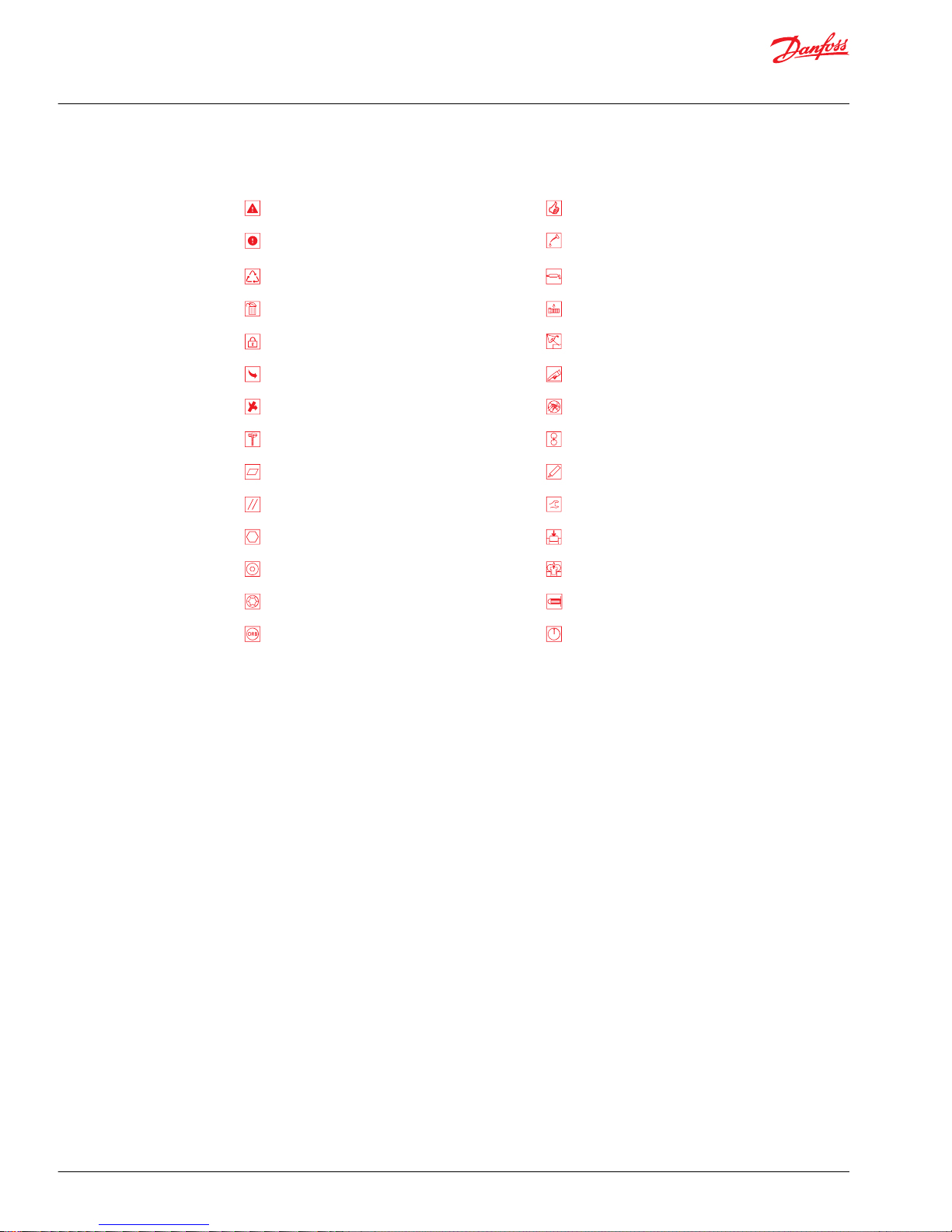
Symbols used in Danfoss literature
WARNING may result in injury Tip, helpful suggestion
CAUTION may result in damage to product or
property
Lubricate with hydraulic fluid
Reusable part Apply grease / petroleum jelly
Non-reusable part, use a new part Apply locking compound
Non-removable item Inspect for wear or damage
Option - either part may exist Clean area or part
Superseded - parts are not interchangeable Be careful not to scratch or damage
Measurement required Note correct orientation
Flatness specification Mark orientation for reinstallation
Parallelism specification Torque specification
External hex head Press in - press fit
Internal hex head Pull out with tool – press fit
Torx head Cover splines with installation sleeve
O-ring boss port Pressure measurement/gauge location or
specification
The symbols above appear in the illustrations and text of this manual. They are intended to communicate
helpful information at the point where it is most useful to the reader. In most instances, the appearance
of the symbol itself denotes its meaning. The legend above defines each symbol and explains its purpose.
General description
Danfoss Series 45 K and L frame open circuit piston pumps convert input torque into hydraulic power.
Rotational force is transmitted through the input shaft to the cylinder block. The input shaft is supported
by tapered roller bearings at the front and rear of the pump and is splined into the cylinder block . A lipseal at the front end of the pump prevents leakage where the shaft exits the pump housing. The spinning
cylinder block contains nine reciprocating pistons. Each piston has a brass slipper connected at one end
by a ball joint. The slippers are held to the swashplate by the spring retainer and block spring. The block
spring also holds the cylinder block to the valve plate. The reciprocating movement of the pistons occurs
as the slippers slide against the inclined swashplate during rotation. Via the valve plate, one half of the
cylinder block is connected to pump inlet and the other half to pump outlet. As each piston cycles in and
out of its bore, fluid is drawn from the inlet and displaced to the outlet thereby imparting power into the
system circuit. A small amount of fluid is allowed to leak from the cylinder block / valve plate and slipper /
swashplate interfaces for lubrication and cooling. Case drain ports are provided to return this fluid to the
reservoir.
The volume of fluid displaced into the system circuit is controlled by the angle of the swashplate. The
swashplate is forced into an inclined position (into stroke) by the bias spring. The servo piston opposes
the action of the bias spring forcing the swashplate out of stroke when hydraulic pressure in the control
circuit rises above the spring force.
The pump control, by varying the pressure at the servo piston, controls the displacement of fluid in the
system circuit. Controls designed for Pressure Compensation (PC) or Load Sensing (LS) are available. For a
detailed description of control operation, refer to Control options, operation.
Service Manual
Series 45 Frame K and L Open Circuit Axial Piston Pumps
Introduction
6 | © Danfoss | August 2016 520L0532 | AX00000040en-US0401
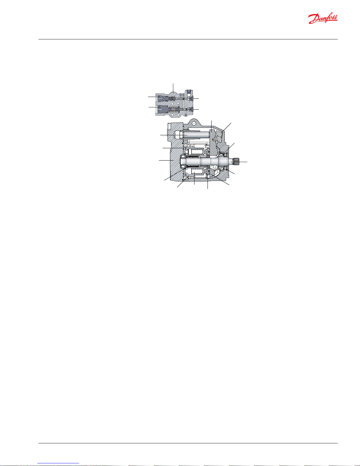
Pump and control sectional view
P101 659E
LS control
(attached to endcap)
LS spool
PC spool
Swashplate
Bias spring
Tapered roller bearing
Input shaft
Shaft seal
Slipper
Slipper retainer
Piston
Cylinder block
Block spring
Endcap
(axial ported)
Valve plate
Servo piston
PC adjustment screw
LS adjustment screw
The system circuit
The pump receives fluid directly from the reservoir through the inlet line. A screen placed in the inlet
protects the pump from large contaminants. The output of the pump is directed to a PVG-32 multisection load sensing directional control valve which directs fluid to the actuators in the system. Fluid
returning from the system is cooled by a heat exchanger and cleaned by a filter before returning to the
reservoir.
The speed of the actuators in the system depends on the volume of fluid being provided by the pump.
The operating pressure varies depending on actuator load, but is limited to an adjustable maximum
setting by the PC section of the pump control and by a system relief valve integrated into the side
module of the PVG valve.
The position of the PVG valve sets the demand for flow in the system and communicates this to the
pump control by means of a hydraulic signal (load sense signal). The pump will provide as much flow to
the system as it demands while limiting the maximum pressure. Therefore flow and pressure in the
system are compensated to meet requirements.
Service Manual
Series 45 Frame K and L Open Circuit Axial Piston Pumps
Introduction
©
Danfoss | August 2016 520L0532 | AX00000040en-US0401 | 7
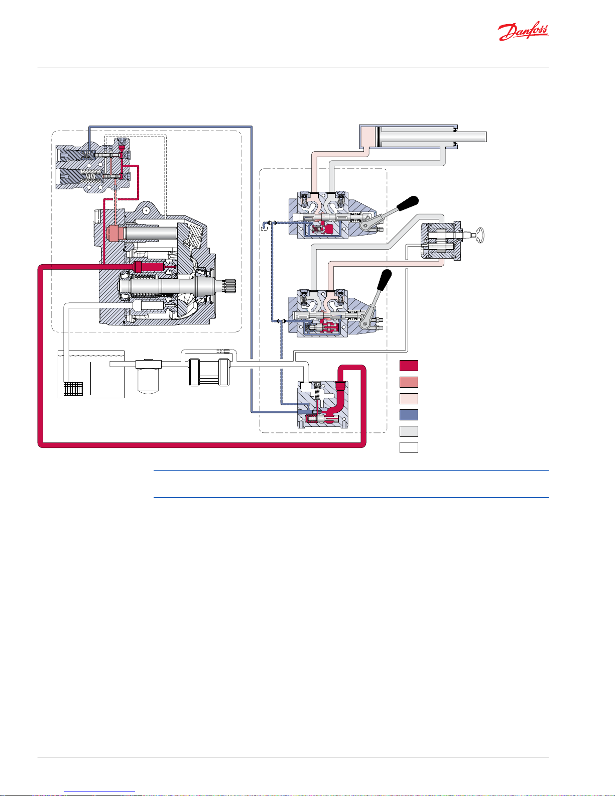
Pictorial circuit diagram
System pressure
Servo pressure
Actuator pressure
Load sense pressure
Actuator return
Suction / case drain /
system return
K/L Frame Series 45
open circuit axial
piston pump with
load sensing control
PVG 32
mulit-section
load
sensing
control
valve
P101 658E
Reservoir
Filter
Heat exchanger
Double-acting cylinder
Bi-directional
gear motor
Full available flow is a function of pump displacement, operating speed, and efficiency. Refer to Series 45
Axial Piston Open Circuit Pumps Technical Information, BLN-10128 for details.
Service Manual
Series 45 Frame K and L Open Circuit Axial Piston Pumps
Introduction
8 | © Danfoss | August 2016 520L0532 | AX00000040en-US0401
General specifications
Type of mounting
SAE-B mounting flange.
Auxiliary mounting pad options
SAE-A, SAE-B, or SAE-B-B
Control options
PC: Pressure Compensator
LS: Load Sensing (with PC)
Port options
Inlet and system ports:
•
SAE flanged ports, code 61 or O-ring boss ports.
•
Axial (end) ports or radial (side) ports.
All other ports:
•
SAE straight thread O-ring boss.
Direction of rotation
Clockwise or counterclockwise.
Installation position
Installation position is discretionary. To satisfy inlet pressure conditions, it is recommended that the
pump always be located below the lowest level of hydraulic fluid in the reservoir. The housing must
always be filled with hydraulic fluid.
Technical specifications
Ratings
Specification Unit Frame L Frame K
Displacement cm3 [ in3] 25 [1.53] 30 [183] 38 [2.32] 45 [2.75]
Input speed minimum min-1 (rpm) 500 500 500 500
continuous 3200 3200 2650 2650
maximum 3600 3600 2800 2800
Working pressure - maximum (peak) bar [psi] 350 [5075] 300 [4350] 350 [5075] 300 [4350]
Continuous working pressure
Flow at rated speed l/min [gal/min] 76.2 [20.3] 90.0 [24.0] 108.3 [20.9] 126.0 [33.6]
Theoretical input torque at maximum displacement
N•m/bar [lbf•in/
1000 psi]
0.395 [243] 0.477 [291] 0.605 [369] 0.716 [437]
Mass moment of inertia of internal rotating components kg•m2[lbm•ft2] 0.0016 [0.037] 0.0015 [0.035] 0.0017 [0.040] 0.0020 [0.047]
Weight Axial ports kg [lbm] 19 [42] 19 [42] 19 [42] 19 [42]
Radial ports 24 [53] 24 [53] 24 [53] 24 [53]
Service Manual
Series 45 Frame K and L Open Circuit Axial Piston Pumps
Technical specifications
©
Danfoss | August 2016 520L0532 | AX00000040en-US0401 | 9
Hydraulic parameters
Inlet pressure
Minimum pressure, continuous = 0.8 bar absolute [23.2 in Hg] (at reduced maximum pump speed)
Minimum pressure, cold start = 0.5 bar absolute [14.8 in Hg]
Pressure compensator valve setting
Minimum: 100 bar [1450 psi]
Maximum: 260 bar [3770 psi]
Case pressure
Maximum continuous: 0.5 bar [7 psi] Above inlet
Intermittent: 2 bar [29 psi] Cold start
Hydraulic fluid
Refer to Danfoss publication Fluids and Filtration BLN-9887 or 520L0463. For information on biodegradable
fluids refer to Biodegradable Hydraulic Fluids 520L0465. See Fluid and filter maintenance for
recommended fluid and filter change intervals.
Temperature range (1)
Intermittent (cold start): - 40° C [- 40° F]
Continuous: 82° C [180° F]
Maximum: (2) 104° C [220° F]
(1)
Hydraulic fluid viscosity must be maintained within the prescribed limits.
(2)
As measured at the hottest point in the system, e.g. drain line.
Fluid viscosity
Viscosity limits
Rating mm2/s (cSt) [SUS]
ν continuous minimum 9 [58]
maximum 110 [500]
ν intermittent minimum 6.4 [47]
maximum (cold start) 1000 [4700]
Filtration
Required cleanliness level: ISO 4406 Class 18/13 or better. Refer to Danfoss publications Fluids and
Filtration BLN-9887 or 520L0463 and Design Guidelines for Selecting and Maintaining the Required Hydraulic
Fluid Cleanliness 520L0465. See Fluid and filter maintenance for recommended fluid and filter change
intervals.
Service Manual
Series 45 Frame K and L Open Circuit Axial Piston Pumps
Technical specifications
10 | © Danfoss | August 2016 520L0532 | AX00000040en-US0401
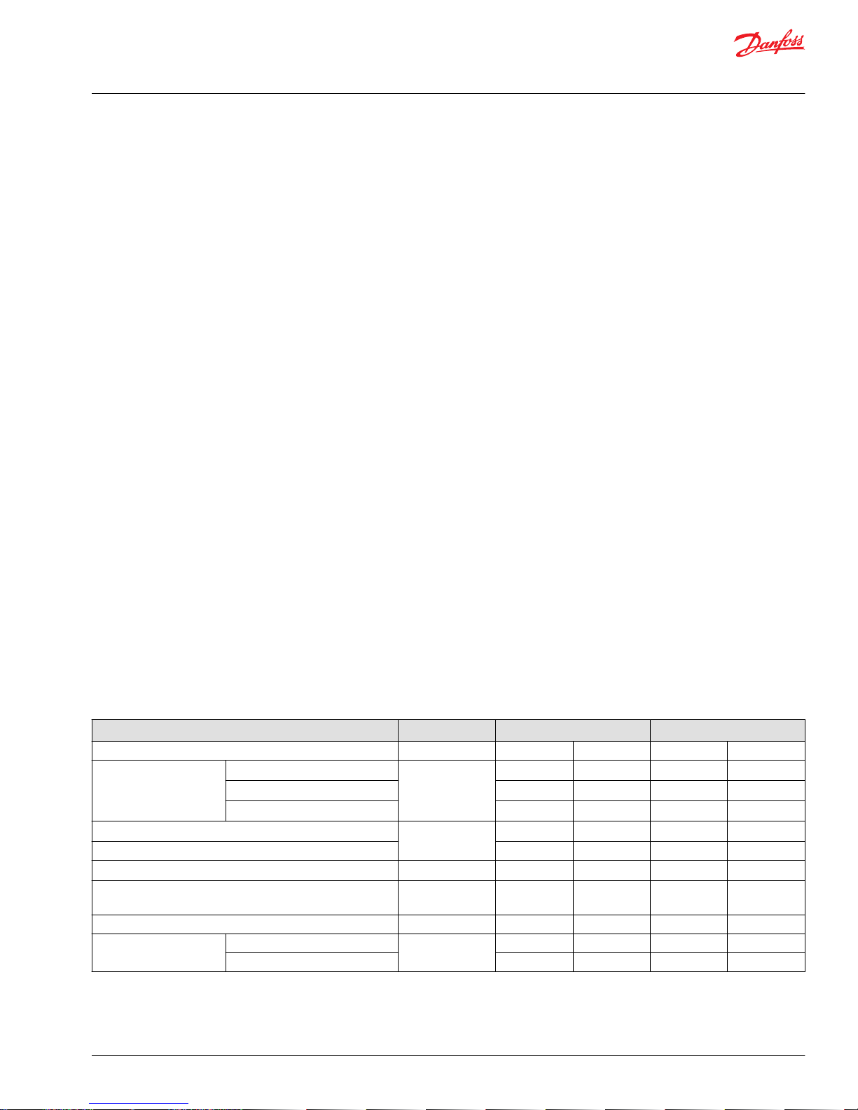
Displacement limiter
Frame K and L Series 45 pumps are available with an optional maximum displacement limiter. If installed,
this longer servo piston will limit the maximum displacement to 92%. This displacement limiter is not
adjustable.
Displacement limiter
P101 660
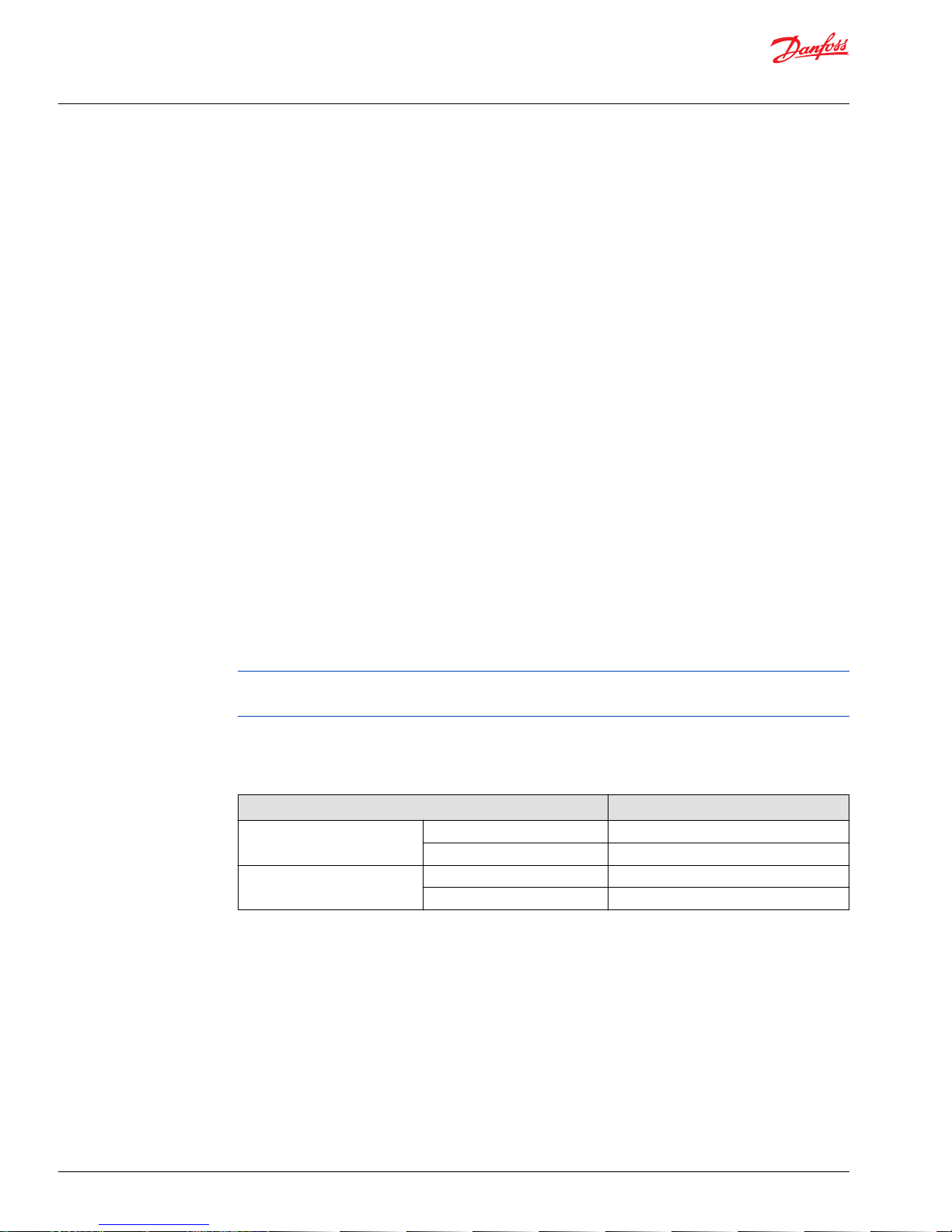
Auxiliary mounting pads
Auxiliary mounting pads are available for all radial ported Series 45 pumps. These pads are typically used
for mounting auxiliary hydraulic pumps.
Since the auxiliary pad operates under case pressure, an O-ring must be used to seal the auxiliary pump
mounting flange to the pad. The drive coupling is lubricated by oil from the main pump case. For details
refer to Series 45 Axial Piston Open Circuit Pumps Technical Information BLN-10128.
Auxiliary mounting pads
P101 661
Input shafts
Series 45 K and L frame pumps are available with a variety of splined, straight keyed, and tapered end
shafts. For information on shafts refer to Series 45 Axial Piston Open Circuit Pumps Technical Information
BLN-10128.
Control options
The Series 45 Frames K and L have two possible control options, a Load Sensing (LS) control with Pressure
Compensator (PC) or a PC only control.
Operation
General
The bias spring (1) acts at all times to push the swashplate (2) to maximum angle causing the pump to
stroke. The servo piston (3) acts against the bias spring to reduce the swashplate angle causing the pump
to de-stroke. Swashplate angle determines pump outlet flow. The pump control, depending on
conditions in the system circuit, sets swashplate angle by metering system pressure to the servo piston.
Service Manual
Series 45 Frame K and L Open Circuit Axial Piston Pumps
Features
©
Danfoss | August 2016 520L0532 | AX00000040en-US0401 | 11
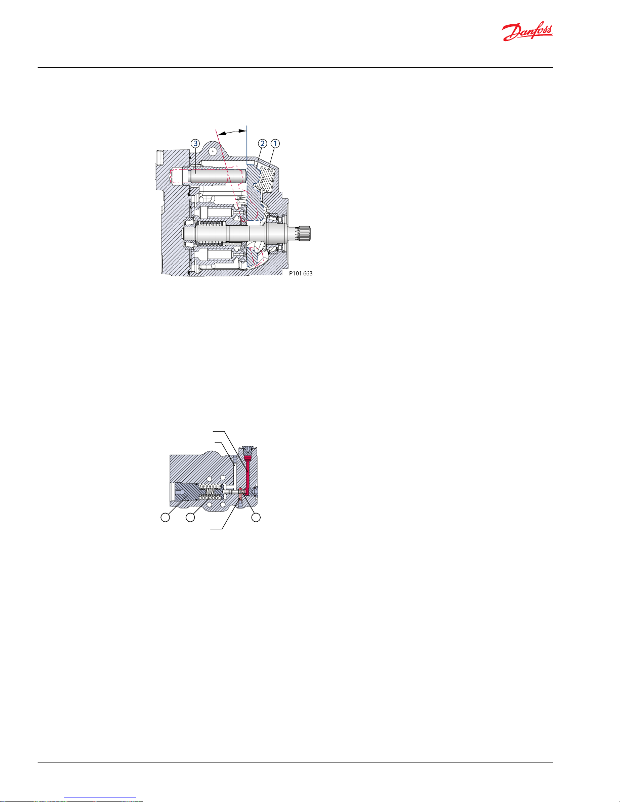
Cross-section pump: Bias spring and servo piston set swashplate position
PC control
The PC control is designed to maintain a constant pressure in the hydraulic circuit as flow varies. The PC
control modulates pump flow accordingly to maintain system pressure at the PC setting as defined by
the PC adjustment screw (4) and spring (5).
When system pressure, acting on the non-spring end of the PC spool (6), overcomes the force of the PC
spring, the spool shifts porting system pressure to the servo piston and the swashplate angle decreases.
When system pressure drops below the PC setting, the PC spring shifts the spool in the opposite
direction connecting the servo piston to pump case and the swashplate angle increases. The swashplate
is maintained at whatever angle is required to keep system pressure at the PC setting.
Cross-section PC control: PC spool shifts to port system pressure to servo piston
System pressure
Servo pressure
Case pressure
P101 662E
44
55
66
LS control
The LS control is designed to match pump flow with system demand. The flow demand of the system is
sensed by the LS control as a pressure drop across the External Control Valve (ECV). As the ECV opens and
closes, the pressure delta across the valve changes. When opening, the delta decreases. When closing,
the delta increases. The LS control then increases or decreases pump flow to the system until the
pressure delta becomes equal to the LS setting as defined by the LS adjustment screw (7) and spring (8).
Service Manual
Series 45 Frame K and L Open Circuit Axial Piston Pumps
Features
12 | © Danfoss | August 2016 520L0532 | AX00000040en-US0401
 Loading...