

Page 1

MAKING MODERN LIVING POSSIBLE
Service Manual
Axial Piston Closed Circuit Pumps
Series 42
powersolutions.danfoss.com
Page 2
Revision history Table of revisions
Date Changed Rev
July 2015 Danfoss layout 0300
Nov 2010 new back page CB
Dec 2009 Major update CA
Jul 2007 Major update BA
Service Manual Series 42 Axial Piston Closed Circuit Pumps
2 520L0638 • Rev 0300 • July 2015
Page 3

Introduction
Overview..............................................................................................................................................................................................5
Warranty.............................................................................................................................................................................................. 5
General instructions........................................................................................................................................................................ 5
Safety precautions............................................................................................................................................................................6
Symbols used in Danfoss literature............................................................................................................................................7
1998 Model Release
Overview..............................................................................................................................................................................................8
Description of change.....................................................................................................................................................................8
Functional Description
Overview..............................................................................................................................................................................................9
General description and cross-sectional view....................................................................................................................... 9
The system circuit.......................................................................................................................................................................... 10
Pump features.................................................................................................................................................................................10
Filtration options............................................................................................................................................................................12
Displacement limiters...................................................................................................................................................................14
Charge check / high pressure relief valves........................................................................................................................... 14
Bypass valves...................................................................................................................................................................................15
Auxiliary mounting pads.............................................................................................................................................................15
Control Options
Manual displacement control (MDC)......................................................................................................................................17
Electrical displacement control (EDC).................................................................................................................................... 17
High current electrical displacement control (HC-EDC).................................................................................................. 18
Non-feedback proportional hydraulic (NFPH) control.....................................................................................................18
Non-feedback proportional electric (NFPE) control..........................................................................................................19
Forward-Neutral-Reverse (FNR) three-position electric control................................................................................... 20
Technical Specifications
Specifications...................................................................................................................................................................................22
Pressure Measurement
Required tools.................................................................................................................................................................................23
Port locations and pressure gauge installation.................................................................................................................. 23
Ports and pressure gauges......................................................................................................................................................... 23
Initial Start-Up Procedure
General...............................................................................................................................................................................................25
Start-up procedure........................................................................................................................................................................25
Fluid and Filter Maintenance
Recommendations........................................................................................................................................................................ 26
Troubleshooting
Overview........................................................................................................................................................................................... 27
System operating hot...................................................................................................................................................................27
System response is sluggish...................................................................................................................................................... 27
System will not operate in either direction.......................................................................................................................... 28
System will not operate in one direction.............................................................................................................................. 29
Neutral difficult or impossible to find.....................................................................................................................................29
Adjustments
Overview........................................................................................................................................................................................... 30
Displacement limiter adjustment............................................................................................................................................ 30
Pump neutral adjustment...........................................................................................................................................................32
Control neutral adjustment for MDC and EDC/HC-EDC.................................................................................................. 33
Minor Repair
Standard procedures....................................................................................................................................................................35
Size and torque for plugs and fittings....................................................................................................................................35
Charge relief valve......................................................................................................................................................................... 37
Optional speed sensor................................................................................................................................................................. 39
Service Manual
Series 42 Axial Piston Closed Circuit Pumps
Contents
520L0638 • Rev 0300 • July 2015 3
Page 4

MDC Module....................................................................................................................................................................................40
HC-EDC and EDC Module............................................................................................................................................................43
MDC/EDC Spool, linkage, and neutral adjustment screw...............................................................................................44
MDC Neutral start / backup alarm switch............................................................................................................................. 46
MDC Solenoid override valve.................................................................................................................................................... 49
FNR, NFPE, and NFPH Controls (bolt-on valves)................................................................................................................. 51
FNR, NFPE, and NFPH Controls (integral valves).................................................................................................................52
System Check Relief (SCR) valves (high pressure relief, charge check, and bypass valves)................................53
Auxiliary pad/charge pump cover........................................................................................................................................... 55
Charge pump...................................................................................................................................................................................57
Servo piston covers and NFPH control orifice.....................................................................................................................60
Loop flushing and loop flushing relief valve........................................................................................................................62
Shaft seal, roller bearing, and shaft replacement...............................................................................................................64
Appendix A - Torques
Torque table.....................................................................................................................................................................................68
Appendix B - Specification Tags
Pre-block point change................................................................................................................................................................70
Post-block point change............................................................................................................................................................. 71
Appendix C - Nomenclature
Pre-block point change nomenclature..................................................................................................................................72
Post-block point change nomenclature................................................................................................................................73
Service Manual Series 42 Axial Piston Closed Circuit Pumps
Contents
4 520L0638 • Rev 0300 • July 2015
Page 5

Overview
This manual includes information for the installation, maintenance, and minor repair of Series 42 axial
piston closed circuit pumps. It includes a description of the unit and its individual components,
troubleshooting information, and minor repair procedures.
Performing minor repairs requires you to remove the unit from the vehicle/machine. Thoroughly clean
the unit before beginning maintenance, or repair activities. Since dirt and contamination are the greatest
enemies of any type of hydraulic equipment, follow cleanliness requirements strictly. This is especially
important when changing the system filter and when removing hoses or plumbing.
A worldwide network of Danfoss Authorized Service Centers (ASCs) is available for major repairs. Danfoss
trains and certifies ASCs on a regular basis. You can locate your nearest ASC using the distributor locator
at www.sauer-danfoss.com. Click on the Sales and Service link.
Warranty
Performing installation, maintenance, and minor repairs according to the procedures in this manual does
not affect your warranty. Major repairs requiring the removal of a unit’s rear cover or front flange voids
the warranty unless done by a Danfoss global service partner.
General instructions
Follow these general procedures when repairing Series 42 variable displacement closed circuit pumps.
Remove the unit
Prior to performing minor repairs, remove the unit from the vehicle/machine. Chock the wheels on the
vehicle or lock the mechanism to inhibit movement. Be aware that hydraulic fluid may be under high
pressure and/or hot. Inspect the outside of the pump and fittings for damage. Cap hoses after removal to
prevent contamination.
Keep it clean
Cleanliness is a primary means of assuring satisfactory pump life, on either new or repaired units. Clean
the outside of the pump thoroughly before disassembly. Take care to avoid contamination of the system
ports. Cleaning parts with a clean solvent wash and air drying is usually adequate.
As with any precision equipment, you must keep all parts free of foreign material and chemicals. Protect
all exposed sealing surfaces and open cavities from damage and foreign material. If left unattended,
cover the pump with a protective layer of plastic.
Replace all O-rings and gaskets
Danfoss recommends replacing all O-rings, gaskets, and seals when servicing. Lightly lubricate all O-rings
with clean petroleum jelly prior to assembly.
Service Manual
Series 42 Axial Piston Closed Circuit Pumps
Introduction
520L0638 • Rev 0300 • July 2015 5
Page 6

Secure the unit
For repair, place the unit in a stable position with the shaft pointing downward. It is necessary to secure
the pump while removing and torquing end covers, controls, and valves.
Safety precautions
Always consider safety precautions before beginning a service procedure. Protect yourself and others
from injury. Take the following general precautions whenever servicing a hydraulic system.
W
Warning
Unintended vehicle or machine movement hazard
When using the RDM in combination with S45 open circuit pumps with LS or EPC be aware that there will
likely be motor movement as long as the engine is turning. Due to the LS-setting of the pump, a standby
pressure will remain in the system even if the normally closed control is fully energized. Lowest standby
pressures to the motor, 15-18bar or above, may be enough to turn the RDM and has the potential to
cause injury or damage.
W
Warning
Flammable cleaning solvents
Some cleaning solvents are flammable. To eliminate the risk of fire, do not use cleaning solvents in an
area where a source of ignition may be present.
W
Warning
Fluid under pressure
Escaping hydraulic fluid under pressure can have sufficient force to penetrate your skin causing serious
injury and/or infection. This fluid may also be hot enough to cause burns. Use caution when dealing with
hydraulic fluid under pressure. Relieve pressure in the system before removing hoses, fittings, gauges, or
components. Never use your hand or any other body part to check for leaks in a pressurized line. Seek
medical attention immediately if you are cut by hydraulic fluid.
W
Warning
Personal safety
Protect yourself from injury. Use proper safety equipment, including safety glasses, at all times.
Service Manual
Series 42 Axial Piston Closed Circuit Pumps
Introduction
6 520L0638 • Rev 0300 • July 2015
Page 7
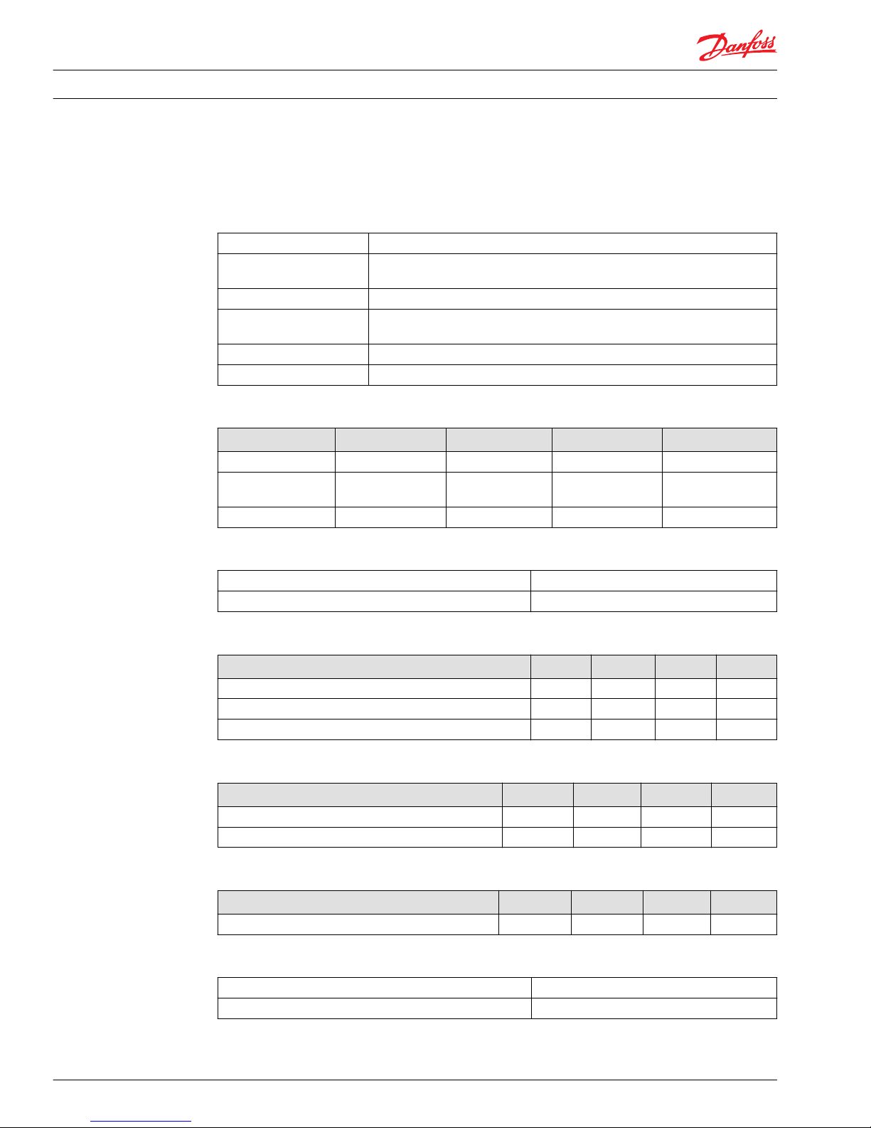
Symbols used in Danfoss literature
WARNING may result in injury Tip, helpful suggestion
CAUTION may result in damage to product or
property
Lubricate with hydraulic fluid
Reusable part Apply grease / petroleum jelly
Non-reusable part, use a new part Apply locking compound
Non-removable item Inspect for wear or damage
Option - either part may exist Clean area or part
Superseded - parts are not interchangeable Be careful not to scratch or damage
Measurement required Note correct orientation
Flatness specification Mark orientation for reinstallation
Parallelism specification Torque specification
External hex head Press in - press fit
Internal hex head Pull out with tool – press fit
Torx head Cover splines with installation sleeve
O-ring boss port Pressure measurement/gauge location or
specification
The symbols above appear in the illustrations and text of this manual. They are intended to communicate
helpful information at the point where it is most useful to the reader. In most instances, the appearance
of the symbol itself denotes its meaning. The legend above defines each symbol and explains its purpose.
Service Manual
Series 42 Axial Piston Closed Circuit Pumps
Introduction
520L0638 • Rev 0300 • July 2015 7
Page 8

Overview
Parts may or may not be interchangeable between pre-1998 and post-1998 model year pumps. Many
parts, including the housing assembly, are unique to the model year change.
Description of change
Housing
The port cover for the control spool (FOB option - 28 cm3 only) changed from a flat plate with two screws
to an SAE O-ring boss plug. The screw holes for the servo covers and four of the six screw holes for the
side cover are deeper to accept a 10 mm longer screw. The two holes next to the charge pump cover
stayed the same length.
Charge pump
The gerotor drive pin changed to a parallel key. A retaining ring was added to the charge pump shaft to
locate the gerotor. The outer step on the gerotor cover was eliminated and the locating pin slot depth
increased.
Auxiliary flange shipping cover
The cover changed to a flat cover plate with a special seal ring (not to be used to seal an auxiliary pump)
under the cover (A pad only).
Charge relief valve
The relief valve changed from a non-adjustable to an adjustable relief valve. This change requires a 1998
upgrade housing.
Spool - loop flushing
The spool changed to become common between the 28 and 41/51 cm3 pumps. This change requires a
1998 upgrade housing.
Service Manual
Series 42 Axial Piston Closed Circuit Pumps
1998 Model Release
8 520L0638 • Rev 0300 • July 2015
Page 9

Overview
This section describes the operation of pumps and their serviceable features. It is a useful reference for
readers unfamiliar with the function of this specific pump.
General description and cross-sectional view
The Series 42 pumps are servo controlled, axial piston pumps designed for closed circuit applications. The
input shaft turns the pump cylinder block containing nine reciprocating pistons that are held to the
swashplate with a block spring. Each piston has a brass slipper connected to one end by a ball joint. The
reciprocating movement occurs as the slippers slide along the inclined swashplate during rotation. As
each piston cycles in and out of its bore, fluid is drawn from the inlet and displaced to the outlet thereby
imparting hydraulic power to the system. Via the valve plate, one half of the cylinder block is connected
to low pressure and the other to high pressure. Clearances allow a small amount of fluid to flow from the
cylinder block/valve plate and slipper/swashplate interfaces for lubrication and cooling. Case drain ports
return this fluid to the reservoir.
The angle of the swashplate controls the volume of fluid displaced into the system. The servo piston
forces the swashplate into an inclined position (into stroke). Internal moments and centering springs
within the servo piston return the swashplate to the neutral position (out of stroke).
Cross section
Roller bearing
Swashplate
Piston
Valve plate
Charge pump
Slipper
Cylinder block
Cylinder block
Service Manual Series 42 Axial Piston Closed Circuit Pumps
Functional Description
520L0638 • Rev 0300 • July 2015 9
Page 10
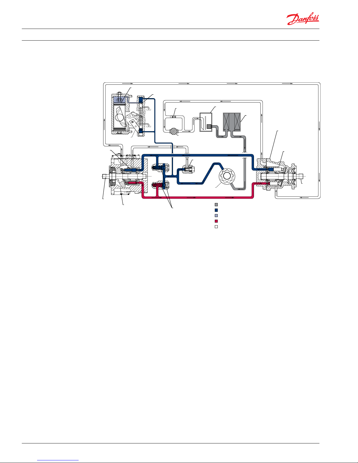
The system circuit
System circuit diagram
Input
shaft
Suction flow
Servo pressure
High pressure
Case flow
Charge pressure
Output
shaft
Cylinder
block
assembly
Filter
Charge
pump
Reservoir
Fixed
displacement
motor
Cylinder
block
assembly
Heat
exchanger
Check valves
with high pressure
relief valves
Variable
displacement
pump
Heat exchanger
bypass
Charge relief
valve
Displacement control valve
Servo control cylinder
Control
handle
Closed circuit operation
Hydraulic lines connect the main ports of the pump to the main ports of the motor. Fluid flows in either
direction from the pump to the motor and back. Either of the hydraulic lines can be under high pressure.
The position of pump swashplate determines which line is high pressure as well as the direction of flow.
Case drain and heat exchanger
Both the pump and motor must drain fluid. A case drain line achieves this. The line connects to the pump
or motor at the top-most drain port in order to maintain an adequate fluid level in the components. Fluid
cooling demands may require a heat exchanger with a bypass valve to cool the case drain fluid before it
returns to the reservoir.
Pump features
Charge pump
The charge pump is necessary to supply fluid to maintain positive pressure in the system loop, to provide
pressure to operate the control system, and to make up for internal leakage and loop flushing flow. To
prevent damage to the transmission, the pump must maintain the specified charge pressure under all
conditions of operation.
Service Manual
Series 42 Axial Piston Closed Circuit Pumps
Functional Description
10 520L0638 • Rev 0300 • July 2015
Page 11
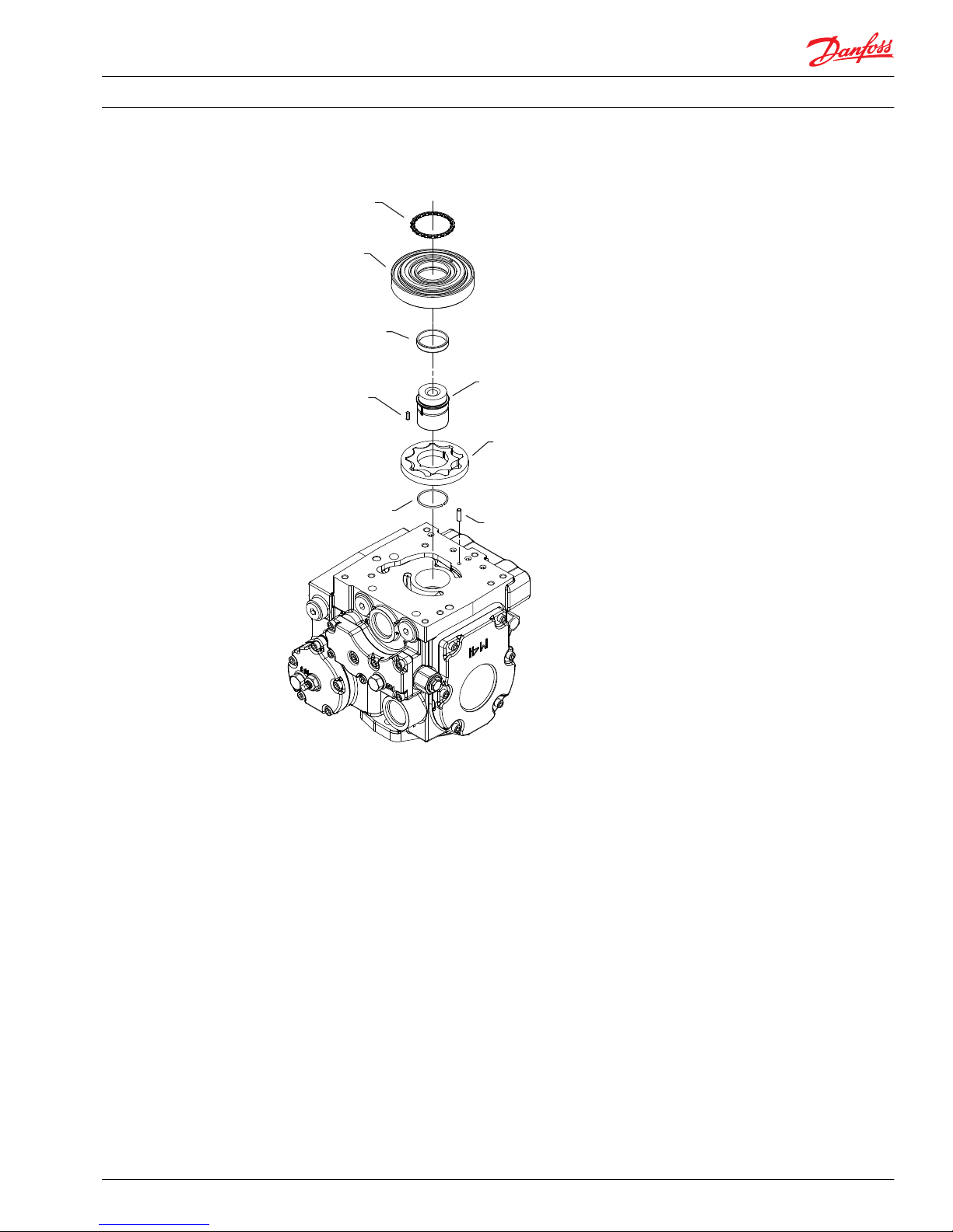
Charge pump
Square key
Retainer
ring
Gerotor set
Coupling
O-ring
Gerotor cover
Orientation
pin
P108 065E
Seal
The charge pump is a fixed-displacement, gerotor type pump. The main pump drives the charge pump
off the main shaft. A spring and poppet style relief valve limits charge pressure.
The standard charge pump is satisfactory for most applications; however, other displacements are
available. A gear pump, mounted to the auxiliary pad, may augment charge flow if additional volume is
required.
Charge relief valve
The charge relief valve maintains charge pressure at a designated level. The charge relief valve is a direct
acting poppet valve which opens and discharges fluid to the pump case when pressure reaches that
level. It is nominally set with the pump running at 1800 rpm. In forward or reverse, charge pressure is
slightly lower than when in neutral position. The model code of the pump specifies the charge relief valve
setting.
Loop flushing valve
A loop flushing valve dumps flow from the low side of the main loop, removing heat and contaminants.
Pumps equipped with an integral loop flushing valve also include a loop flushing relief valve. The loop
flushing relief valve poppet includes an orifice that controls flushing flow under most conditions. A
combination of orifice size and charge pressure relief setting produces a specific flushing flow.
Service Manual
Series 42 Axial Piston Closed Circuit Pumps
Functional Description
520L0638 • Rev 0300 • July 2015 11
Page 12
Charge relief, loop flushing relief, and loop flushing valve
Loop flushing
spoo
l
Loop flushing
relief valve
Charge relief
valve
Loop flushing
defeat spool
P108 095E
Filtration options
Series 42 pumps may be equipped with provisions for either suction or charge pressure filtration to filter
the fluid entering the circuit.
Suction filtration
The suction filter is in the circuit between the reservoir and the inlet to the charge pump.
Suction filtration
Reservoir
Filter
Charge
pump
Charge
relief
valve
To pump case
To low pressure
side of loop and
servo control
Strainer
P001603E
Service Manual
Series 42 Axial Piston Closed Circuit Pumps
Functional Description
12 520L0638 • Rev 0300 • July 2015
Page 13

Charge pressure filtration
The pressure filter is remotely mounted in the circuit after the charge pump.
You may use partial or full flow pressure filtration circuits with Series 42 pumps. Without a filter adapter,
suction filtration is the only option.
Partial flow pressure filtration
Reservoir
Filter
Charge pump
Charge
relief valve
To pump case
Strainer
To low pressure
side of loop and
servo control
Full flow pressure filtration
Reservoir
Filter
with bypas s
Charge
pump
Charge
relief
pump
To pump case
To low pressure
side of loop and
se rvo contro l
Strainer
P001605E
Service Manual Series 42 Axial Piston Closed Circuit Pumps
Functional Description
520L0638 • Rev 0300 • July 2015 13
Page 14
Filtration adapters
Full flow
pressure
filtration
Full flow
suction
filtration
Partial flow
pressure
filtration
P108 066E
Displacement limiters
Series 42 pumps are available with mechanical displacement limiters in the servo covers. The
displacement limiters can limit displacement of the pump to any value from maximum to zero in either
direction.
Displacement limiters
Displacement limiter
(factory set for maximum displacement)
Displacement limiter
(set for reduced maximum displacement)
Servo control
cylinder
Charge check / high pressure relief valves
All series 42 pumps have a combination charge check/high pressure relief valve. The charge check
function allows pressurized flow from the charge pump to enter the low pressure side of the loop. This
flow is necessary to replenish fluid discharged to the pump/motor case for lubrication and cooling
requirements. Since the pump can operate in either direction, it uses two charge check valves to direct
the charge supply into the low pressure side.
Service Manual
Series 42 Axial Piston Closed Circuit Pumps
Functional Description
14 520L0638 • Rev 0300 • July 2015
Page 15

High pressure relief valves are available in a range of settings as shown in the model code. The model
code may specify individual pressure settings. The high pressure relief valve settings are referenced to
charge pressure and are set at 3.8 l/min [1 US gal/min] of flow.
High pressure relief valve
High pressure
side of working loop
Charge check and
high pressure
relief valve
Bypass valves
Optional bypass plungers are available for use when it is necessary to move the vehicle or mechanical
function and the prime mover is not running.
Together, these valves connect both sides of the main hydraulic circuit, allowing fluid to circulate without
rotating the pump and prime mover.
The bypass function is integral to the charge check/high pressure relief valve assembly. Depressing the
plunger in the plug of the valve assembly opens the valve. The valve remains open until the prime mover
restarts or pressure builds in the system and causes the valve the close. You must depress the plungers in
both of the check/relief valve assemblies for proper bypass operation.
C
Caution
Bypass valves are for moving a machine or vehicle for very short distances at very slow speeds. They are
not tow valves. If pressure builds within the system, the valves may close causing damage to the pump
and motor or prime mover. Move the vehicle/machine at no more than 20% of top speed for no more
than three minutes.
Charge check and high pressure relief valves with bypass
To/from other
bypass valve
To/from
working loop
Charge check and
high pressure
relief valve
Bypass
plunger
P100394E
Auxiliary mounting pads
SAE A and SAE B auxiliary mounting flanges are available on all Series 42 pumps and are integral to the
charge pump cover. This flange allows mounting of auxiliary hydraulic pumps and mounting of
additional Series 42 pumps to make tandem pumps. The pads allow full through-torque capability.
Service Manual
Series 42 Axial Piston Closed Circuit Pumps
Functional Description
520L0638 • Rev 0300 • July 2015 15
Page 16
Auxiliary mounting pads
Pad seal
Cover plate
O-ring
Charge pump cover
P108 096E
U085
U035 (x8)
Service Manual Series 42 Axial Piston Closed Circuit Pumps
Functional Description
16 520L0638 • Rev 0300 • July 2015
Page 17
Manual displacement control (MDC)
The Manual Displacement Control (MDC) uses a mechanical input to operate the control spool in the
pump. A cam connects the input handle to the control spool allowing manipulation of the operating
curve using different cam profiles. The control spool modulates the pressure balance across the pump’s
servo piston. The angle of the swashplate is proportional to the angular position of the control input. A
mechanical feedback linkage moves the control spool toward neutral as the swashplate angle reaches
the commanded position. Mechanical feedback allows the pump to hold very accurately at the
commanded displacement. Centering springs and internal moments return the swashplate to neutral
position in the absence of control input.
MDC on series 42 pump
Solenoid override valve
A solenoid override valve is available for the manual displacement control. This safety feature shunts the
servo piston allowing the pump to return to neutral when activated. Normally open or normally closed
options are available.
Neutral start switch (NSS)
The Neutral Start Switch (NSS) is an optional cam-operated ball-type microswitch. When connected
properly to the vehicle’s electrical system, the NSS ensures that the prime mover will start only when the
control input shaft is in the neutral position.
Back-up alarm switch (BAS)
The Back-up Alarm Switch (BAS) is available for the MDC and works in association with the NSS. When
connected properly to the vehicle’s electrical system, the BAS can sound an alarm when the control
commands the vehicle into reverse. One cam and switch assembly controls both functions. Repositioning
the cam accommodates both clockwise and counterclockwise control handle rotation to reverse
direction.
Electrical displacement control (EDC)
The Electrical Displacement Control (EDC) is a two-stage control using a DC input current to control
pump displacement. Stage one, the Pressure Control Pilot (PCP) valve, uses the DC input to operate a
torque motor which drives a flapper valve. The flap in the PCP blocks a portion of flow from one or the
other of two nozzles. The two nozzles modulate pressure balance across a sensing piston in the control.
The control piston is connected to the control spool in the pump by a pin and linkage. The control spool
modulates the differential pressure across the pump’s servo piston, this is stage two. The angle of the
swashplate is proportional to the input current. A mechanical feedback linkage moves the control spool
toward neutral as the swashplate angle reaches the commanded position. Mechanical feedback allows
Service Manual
Series 42 Axial Piston Closed Circuit Pumps
Control Options
520L0638 • Rev 0300 • July 2015 17
Page 18
the pump to hold very accurately at the commanded displacement. Centering springs and internal
moments return the swashplate to neutral position in the absence of control input.
EDC on series 42 pump
High current electrical displacement control (HC-EDC)
The High Current Electrical Displacement Control (HC-EDC) is a two-stage control using a DC input
current with Pulse With Modulation (PWM) to control pump displacement. Stage one uses two
Proportional Pressure Reducing Valves (PPRV), to provide reducing pressure proportional to the input
current. The pressure from each PPRV is provided to each end of the sensing piston in the control: this is
stage one. The sensing piston is connected to the control spool in the pump by a pin and linkage. The
control spool modulates the differential pressure across the pump’s servo piston, this is stage two. The
angle of the swashplate is proportional to the input current.
A mechanical feedback linkage moves the control spool toward neutral as the swashplate angle reaches
the commanded position. Mechanical feedback allows the pump to hold very accurately at the
commanded displacement. Centering springs and internal moments return the swashplate to neutral
position in the absence of control input.
HC-EDC on series 42 pump
Non-feedback proportional hydraulic (NFPH) control
The Non-Feedback Proportional Hydraulic (NFPH) control is a hydraulic displacement control. External
valving supplies an input pressure directly to the pump servo piston via control ports X1 and X2 to
control pump displacement.
Pump displacement is proportional to the pressure difference across the servo piston. However, because
this control does not use mechanical feedback, displacement also depends upon input speed and system
Service Manual
Series 42 Axial Piston Closed Circuit Pumps
Control Options
18 520L0638 • Rev 0300 • July 2015
Page 19
pressure. This characteristic provides a power limiting function by reducing displacement as system
pressure increases.
NFPH control on series 42 pump
Non-feedback proportional electric (NFPE) control
The Non-Feedback Proportional Electric (NFPE) control is an electric control. A PWM input signal to one of
two solenoids on the control valve ports charge pressure to one side of the servo piston.
Pump displacement is proportional to the signal current. However, because this control does not use
mechanical feedback, displacement also depends on input speed and system pressure. This characteristic
provides a power limiting function by reducing displacement as system pressure increases.
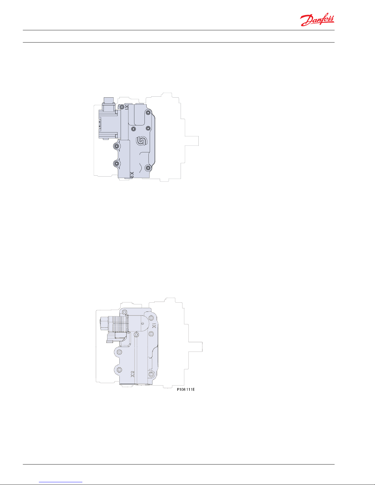
NFPE control on series 42 pump (28/32cc)
Service Manual
Series 42 Axial Piston Closed Circuit Pumps
Control Options
520L0638 • Rev 0300 • July 2015 19
Page 20
NFPE control on series 42 pump (41/51cc)
P100 415
Forward-Neutral-Reverse (FNR) three-position electric control
The Forward-Neutral-Reverse (FNR) is a three-position control. It uses a 12 or 24 Vdc electrically operated
spool valve to port pressure to either side of the servo piston. Energizing one of the two solenoids will
cause the pump to go to its maximum displacement in the corresponding direction. The FNR control
does not use mechanical feedback.
All functions of the three position (FNR) electric control are preset at the factory.
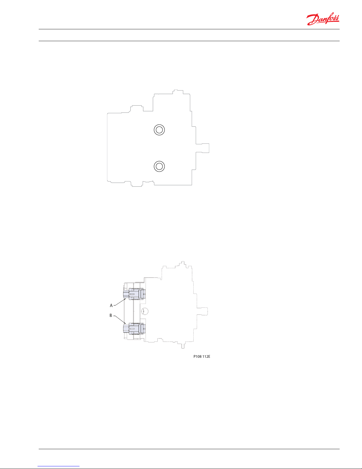
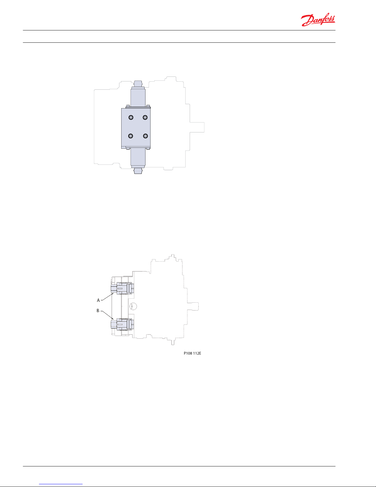
FNR control on series 42 pump (28/32cc)
Service Manual
Series 42 Axial Piston Closed Circuit Pumps
Control Options
20 520L0638 • Rev 0300 • July 2015
Page 21
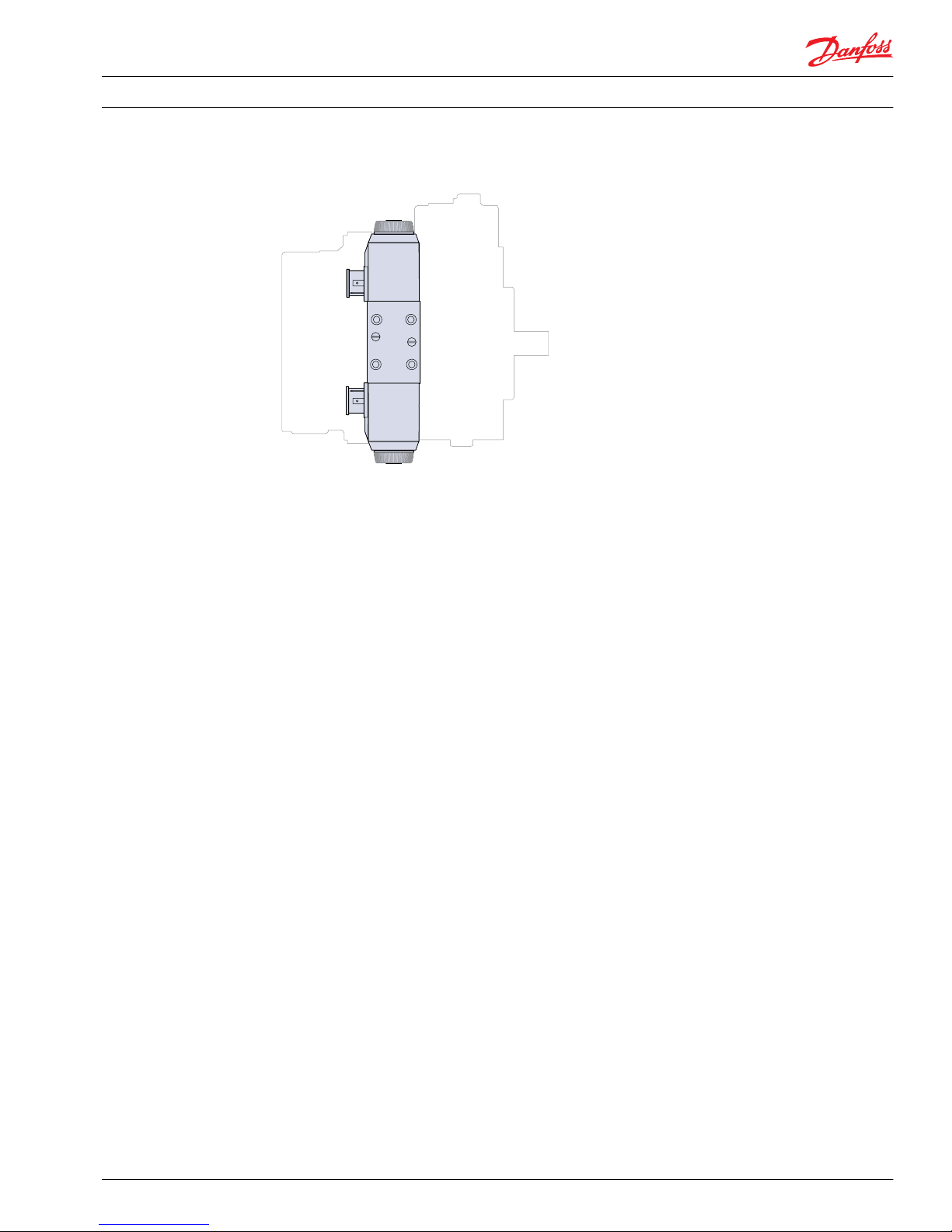
FNR control on series 42 pump (41/51cc)
Service Manual Series 42 Axial Piston Closed Circuit Pumps
Control Options
520L0638 • Rev 0300 • July 2015 21
Page 22
Specifications
General specifications
Product line Series 42 pumps
Pump type In-line, axial piston, positive displacement variable pumps including cradle
swashplate and servo control
Direction of input rotation Clockwise or counterclockwise available
Installation position Pump installation recommended with the control at the top or side. Consult Danfoss
for non-conformance guidelines. Housing must always be filled with hydraulic fluid.
Filtration configuration Suction or charge pressure filtration
Other system requirements Independent braking system, suitable reservoir and heat exchanger.
Hardware specifications
Model 28 32 41 51
Pump configuration Single pump Single pump Single pump Single pump
Displacement
cm3/rev [in3/rev]
28 [1.71] 31.8 [1.94] 41 [2.50] 51 [3.11]
Mass kg [lbm] 34.5 [76] 34.5 [76] 42 [92] 42 [92]
Case pressure
Rated pressure bar [psi] 3.4 [50]
Maximum pressure (cold start) bar [psi] 10.5 [150]
Speed limits
Frame size cm
3
28 32 41 51
Minimum speed min¯¹ (rpm) 500 500 500 500
Rated speed at maximum displacement min¯¹ (rpm) 3400 3000 3200 2900
Maximum speed at maximum displacement min¯¹ (rpm) 3750 3400 3600 3400
System pressure
Frame size cm
3
28 32 41 51
Rated pressure bar [psi] 385 [5584] 385 [5584] 385 [5584] 350 [5076]
Maximum pressure bar [psi] 415 [6019] 415 [6019] 415 [6019] 385 [5584]
Theoretical flow
Frame size cm
3
28 32 41 51
Theoretical flow at rated speed l/min [US gal/min] 95.2 [25.1] 95.4 [25.2] 131 [34.6] 148 [39.1]
Inlet pressure
Rated pressure (absolute) bar [in Hg vacuum] 0.8 [6]
Minimum pressure (absolute) (cold start) bar [in Hg vacuum] 0.2 [24]
Service Manual Series 42 Axial Piston Closed Circuit Pumps
Technical Specifications
22 520L0638 • Rev 0300 • July 2015
Page 23
Required tools
You can perform the service procedures in this manual using common mechanic’s hand-tools. Calibrate
gauges frequently to ensure accuracy. Use snubbers to protect pressure gauges.
Port locations and pressure gauge installation
A pump with a manual displacement control (MDC) and no filtration adapter is shown. With nonfeedback controls, the positions of the case drains may vary. With a filtration adapter, the porting in the
filtration options area varies.
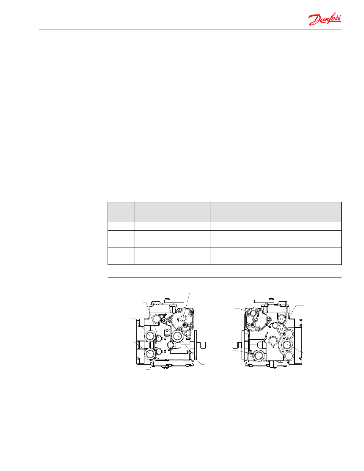
Ports and pressure gauges
Proper service and diagnosis may require pressure measurement at various points in the hydraulic circuit.
The Series 42 pump has several locations at which to take these measurements. The following illustration
shows the locations of the various gauge ports. The table shows the recommended gauge size and the
fitting size for each port. Refer to this information when installing pressure gauges.
Gauge ports
Gauge
port
Pressure measured Recommended gauge
size
O-ring boss
28/32 cc 41 / 51 cc
M1 & M2 System pressure for ports A and B 600 bar [8700 psi] 9/16/-18 9/16/-18
M3 Charge pressure 60 bar [870 psi] 3/4-16 * 3/4-16 *
M4 & M5 Servo pressure 60 bar [870 psi] 9/16-18 9/16-18
L1 & L2 Case pressure 35 bar [510 psi] 1-1/16-12 1-5/16-12
S Charge pump inlet pressure 1 bar [30 in Hg vacuum] 1-1/16-12 1-5/16-12
* Some older models may use a 9/16-18 O-ring fitting.
28/32 cm3 base unit with MDC and no filtration adapter
Servo pressure
gauge port M5
Case Drain
Port L2
Charge pressure
gauge port M3
(charge pressure
supply for no
charge pump
option)
Charge pump
inlet port S
Servo pressure
gauge port M4
Case drain
port L1
System pressure
gauge port M2
System
pressure
port B
System
pressure
port A
System pressure
gauge port M1
RIGHT SIDE VIEW
LEFT SIDE VIEW
P108 067E
Service Manual
Series 42 Axial Piston Closed Circuit Pumps
Pressure Measurement
520L0638 • Rev 0300 • July 2015 23
Page 24

41/51 cm3 base unit with MDC and no filtration adapter
Case drain
port L2
Servo pressure
gauge port M5
Charge pressure
gauge port M3
Charge pump
inlet port S
Servo pressure
gauge port M4
Case drain
port L1
System pressure
gauge port M2
System
pressure
port B
System
pressure
port A
System pressure
gauge port M1
LEFT SIDE VIEW
RIGHT SIDE VIEW
P108 068E
Filtration adapters (28/32 cm3, and 41/51 cm3 models)
Inlet from
filter,port E
Charge pressure
gauge,port M3
Outlet to
filter,port D
Charge pressure
gauge,port M3
P108 084E
Service Manual Series 42 Axial Piston Closed Circuit Pumps
Pressure Measurement
24 520L0638 • Rev 0300 • July 2015
Page 25

General
Follow this procedure when starting-up a new Series 42 installation or when restarting an installation in
which the pump has been removed.
W
Warning
Unintended movement of the machine or mechanism may cause injury to the technician or bystanders.
To protect against unintended movement, secure the machine or disable/disconnect the mechanism
while servicing.
Prior to installing the pump, inspect for damage incurred during shipping. Make certain all system
components (reservoir, hoses, valves, fittings, heat exchanger, etc.) are clean prior to filling with fluid.
Start-up procedure
1. Connect the pump to the prime mover. Ensure that pump shaft is properly aligned with the shaft of
the prime mover.
C
Caution
Incorrect shaft alignment may result in damage to drive shaft, bearings, or seal which can cause
external oil leakage.
2. Fill the reservoir with recommended hydraulic fluid. Always filter fluid through a 10 micron absolute
filter pouring into the reservoir. Never reuse hydraulic fluid.
3. Fill the main pump housing with clean hydraulic fluid. Pour filtered oil directly into the upper most
case drain port.
4. Fill the inlet line leading from the pump to the reservoir. Check the inlet line for properly tightened
fittings and be certain it is free of restrictions and air leaks.
5. To ensure the pump stays filled with oil, install the case drain line in the upper most case drain port.
6. Install a gauge at port M2 to monitor system pressure during start up.
Follow recommendations in the vehicle/machine operator’s manual for prime mover start up
procedures.
7. While watching the pressure gauge at M2, jog the prime mover or run at the lowest possible speed
until system pressure builds to normal levels (minimum 11 bar [160 psi]). Once system pressure is
established, increase to full operating speed. If the pump does not maintain system pressure, shut
down the prime mover, determine cause, and take corrective action. Refer to Troubleshooting.
8. Operate the hydraulic system for at least fifteen minutes under light load conditions.
9. Check and adjust control settings as necessary after installation. Refer to Adjustments.
10. Shut down the prime mover and remove the pressure gauge. Replace plug at port M2.
11. Check the fluid level in the reservoir; add clean filtered fluid if necessary.
The pump is now ready for operation.
Service Manual
Series 42 Axial Piston Closed Circuit Pumps
Initial Start-Up Procedure
520L0638 • Rev 0300 • July 2015 25
Page 26

Recommendations
To ensure optimum life of Series 42 products, perform regular maintenance of the fluid and filter.
Contaminated fluid is the main cause of unit failure. Take care to maintain fluid cleanliness when
servicing.
Check the reservoir daily for proper fluid level, the presence of water, and rancid fluid odor. Water in the
fluid may be noted by a cloudy or milky appearance or free water in the bottom of the reservoir. Rancid
odor indicates the fluid has been exposed to excessive heat. Change the fluid immediately if these
conditions occur. Correct the problem immediately.
Change the fluid and filter per the vehicle/machine manufacturer’s recommendations or at these
intervals:
Fluid and filter change intervals
Sealed reservoir 2000 hours
Breather reservoir 500 hours
Change the fluid more frequently if it becomes contaminated with foreign matter (dirt, water, grease,
etc.) or if the fluid is subjected to temperature levels greater that the recommended maximum.
Dispose of used hydraulic fluid properly. Never reuse hydraulic fluid.
Change filters whenever the fluid is changed or when the filter indicator shows that it is necessary to
change the filter. Replace all fluid lost during filter change.
Service Manual
Series 42 Axial Piston Closed Circuit Pumps
Fluid and Filter Maintenance
26 520L0638 • Rev 0300 • July 2015
Page 27

Overview
This section provides general steps to follow if you observe certain undesirable system conditions. Some
of the items are system specific. Always observe the safety precautions listed in the introduction of this
manual. If standard troubleshooting procedures do not remedy the problem, contact a Danfoss Global
Service Partner.
System operating hot
Item Description Action
Oil level in reservoir Insufficient hydraulic fluid will not
meet the cooling demands of system.
Fill the reservoir to the proper level
with clean hydraulic oil.
Heat exchanger (if equipped) The heat exchanger is not sufficiently
cooling the system.
Check the air flow and input air
temperature for the heat exchanger.
Clean, repair, or replace the heat
exchanger as necessary.
Bypass valve A partially activated bypass valve may
result in heat generation within the
system.
Verify that the bypass valve is fully
closed and that the valve is seating
properly. Repair or replace it as
necessary.
SCR (System Check / Relief) Valves A partially activated SCR valve or SCR
valves with relief settings too low may
result in heat generation within the
system.
Verify that the SCR valve is seating
properly and is at the correct relief
setting. Repair or replace it as
necessary.
Oil filters Clogged oil filters may result in an
insufficient supply of cool oil to the
system.
Inspect the oil filters and verify that
they are still operable. Replace them if
necessary.
Machine load Excessive loads or extreme duty cycles
could result in the pump and/ or motor
operating at speeds and pressures
beyond system design limitations.
Verify that the machine is operating
within the parameters for which it was
designed. If necessary, reduce the load
on the machine.
System response is sluggish
Item Description Action
Reservoir oil level There is an insufficient amount of
hydraulic fluid, resulting in an
inadequate supply for the system loop.
Fill the reservoir to the proper level
with clean hydraulic fluid.
Input control signal (linkage,
current, or pressure)
The pump is receiving a faulty control
signal: (MDC - binding or broken
linkage; EDC - faulty or inadequate
electrical signal; HDC - blocked or
incorrectly orificed control lines).
Verify that the input signal is correct
and identical in both directions.
Pump control A damaged pump control or control
spool will not correctly transmit the
control input signal to the pump.
Verify that the pump’s control is
operating properly and that the
control spool is not damaged or worn
and moves freely within its bore. Clean,
repair, or replace it as necessary.
Bypass valve A partially activated bypass valve will
cause cross port leakage.
Verify that the bypass valve is closed
and that the valve is seating properly.
Clean, repair, or replace it as necessary.
SCR (system check / relief) valves One or both of the SCR valves may be
binding within their bores.
Verify that the SCR valves operate
freely. Repair or replace them as
necessary.
Service Manual Series 42 Axial Piston Closed Circuit Pumps
Troubleshooting
520L0638 • Rev 0300 • July 2015 27
Page 28

Item Description Action
Charge pressure (in neutral) The is low charge pressure resulting
from a damaged charge pump or low
charge pressure relief valve setting.
Inspect the charge pump for damage
and verify the charge pressure relief
valve setting. Repair or replace it as
necessary.
Charge pressure (in stroke) There is low charge pressure resulting
from internal leakage within the
system.
Repair or replace the component or
components within the system causing
the internal leakage.
Servo pressure There is insufficient pressure
differential across the servo piston.
Check servo pressures at port M4 and
M5 to verify sufficient pressure delta.
Verify that the servo supply and drain
paths are unobstructed and that any
orifices are of the correct size and free
of debris. Clean, repair, or replace as
necessary.
Charge pump The charge pump has been damaged
or installed with the incorrect
rotational orientation.
Verify that the charge pump is in good
working order and that it is correctly
installed. Repair or replace it as
necessary.
System will not operate in either direction
Item Description Action
Oil level in reservoir There is insufficient hydraulic fluid to
supply the system loop.
Fill the reservoir to the proper level
with clean hydraulic oil.
Input control signal
(linkage, current, or pressure)
The pump is receiving a faulty control
signal: (MDC - binding or broken
linkage; EDC - faulty or inadequate
electrical signal; HDC - blocked or
incorrectly orificed control lines).
Verify that the input signal is correct
and identical in both directions. Adjust,
clean, repair, or replace the input
device as necessary.
Oil filters Clogged oil filters may result in an
insufficient supply of oil to the system.
Inspect the oil filters and verify that
they are still serviceable. Replace them
as necessary.
Bypass valve A partially activated bypass valve may
result in a cross port leakage.
Verify that the bypass valves are closed
and that the valves are seating
properly. Clean, repair, or replace them
as necessary.
Charge pressure
(in neutral)
Charge pressure may be insufficient to
recharge the system loop.
Inspect the charge pump for damage
and verify that the charge pressure
relief valve is at the proper setting.
Repair or replace it as necessary.
Charge pressure
(in stroke)
There is low charge pressure resulting
from internal leakage within the
system.
Repair or replace the component or
components within the system causing
the internal leakage.
Servo pressure There is an insufficient pressure
differential across the servo piston.
Check servo pressures to verify
sufficient pressure delta. Verify that the
servo supply and drain paths are
unobstructed and that any orifices are
of the correct size and free of debris.
Clean, repair, or replace them as
necessary.
Charge pump The charge pump is damaged or has
been installed with the incorrect
rotational orientation.
Verify that the charge pump is in good
working order and that it is correctly
installed. Repair or replace it as
necessary.
Service Manual Series 42 Axial Piston Closed Circuit Pumps
Troubleshooting
28 520L0638 • Rev 0300 • July 2015
Page 29

Item Description Action
SCR (system check / relief) valves The SCR valves are malfunctioning or
improperly set.
Verify that the SCR valves are operating
and properly set. Repair or replace
them as necessary.
Displacement limiters Displacement limiters may be
improperly adjusted such that the
servo piston is locked in place.
Verify that the displacement limiters
are adjusted to the proper setting.
System will not operate in one direction
Item Description Action
Input control signal (linkage,
current, or pressure)
The pump is receiving a faulty control
signal: (MDC - binding or broken
linkage; EDC - faulty or inadequate
electrical signal; HDC - blocked or
incorrectly orificed control lines).
Verify that the input signal is correct
and identical in both directions. Adjust,
clean, repair, or replace the control
module as necessary.
SCR (System Check/Relief) valves The SCR valves are malfunctioning or
improperly set.
Verify that the SCR valves are operating
properly. Repair or replace them as
necessary.
Pump control A damaged or biased pump control
may be sending a signal commanding
the pump to stroke only in one
direction.
Verify that the pump’s control is
functioning properly. Repair or replace
it as necessary.
Servo pressure The drain or supply path to one side of
the servo piston may be blocked.
Verify that the servo supply and drain
paths are unobstructed and that any
orifices are of the correct size and free
of debris. Clean or repair them as
necessary.
Displacement limiters (if
equipped)
The displacement limiters may be
improperly adjusted such that the
servo piston is prevented from moving
in one direction.
Verify that the displacement limiters
are adjusted properly.
Neutral difficult or impossible to find
Item Description Action
Input control signal (linkage,
current, or pressure)
The pump is receiving a faulty control
signal: (MDC - binding or broken
linkage; EDC - faulty or inadequate
electrical signal; HDC - blocked or
incorrectly orificed control lines).
Verify that the input signal is correct
and identical in both directions. Adjust,
clean, repair, or replace control module
as necessary.
System pressure With no input signal to the control, a
pressure delta may exist between the
two sides of the working loop.
Readjust pump neutral setting. Refer to
adjustment procedure.
Servo pressure With no input signal to the control, a
pressure delta may exist across the
servo piston.
Readjust the control neutral setting.
Refer to adjustment procedure.
PCP pressure (EDCs only) With no input signal to the control, a
pressure difference may exist across
the control spool.
Replace the EDC.
Service Manual Series 42 Axial Piston Closed Circuit Pumps
Troubleshooting
520L0638 • Rev 0300 • July 2015 29
Page 30

Overview
This section offers instruction on how to perform adjustments to the Series 42 pump. Read through the
entire procedure before beginning any service activity.
Displacement limiter adjustment
Mount the pump on a test stand capable of measuring system flow from the A and B ports.
1. Loosen the displacement limiter seal lock nut (L025), but do not remove it.
2. Start the prime mover and place the pump into full stroke in one direction. Note the system output
flow from either the A or B system port.
3. Adjust the displacement limiter adjustment screw (L020) until the desired output flow is reached.
Turning the displacement limiter adjustment screw clockwise decreases the maximum output flow
setting. Turning the displacement limiter adjustment screw counter clockwise increases the
maximum output flow setting.
W
Warning
The seal nut lock nut must be retorqued after every adjustment and the limiter screw must have full
thread engagement in the servo piston cover to prevent unexpected changes in operating conditions
and to prevent external leakage during unit operation.
The pump achieves overall maximum flow when the displacement limiter does not contact the servo
piston while the unit is in full stroke.
One full turn of the displacement limiter adjustment screw results in approximate flow output
changes per the table.
4. Once you achieve the proper output flow, torque the displacement limiter seal lock nut (L025) to 23
N•m [17 lbf•ft] while holding the position of the adjustment screw (L020).
5. If required, repeat this procedure using the opposite displacement limiter to set the output flow in
the other direction.
Displacement limiter adjustment
Size Displacement change per turn
28 cm
3
3.6 cm3/rev [0.22 in3/rev]
32 cm
3
4.1 cm3/rev [0.25 in3/rev]
41 cm
3
5.0 cm3/rev [0.31 in3/rev]
51 cm
3
6.2 cm3/rev [0.38 in3/rev]
Service Manual Series 42 Axial Piston Closed Circuit Pumps
Adjustments
30 520L0638 • Rev 0300 • July 2015
Page 31

Displacement limiters
L025
Displacement
limiter seal
lock nut
13 mm
3 N•m
[17 lbf•ft]
L020
Displacement
limiter
4 mm
L001
Servo
piston
cover
M025
Displacement
limiter seal
lock nut
13 mm
3 N•m
[17 lbf•ft]
M020
Displacement
limiter
4 mm
RIGHT SIDE VIEW (M4)
LEFT SIDE VIEW (M5)
M001
Servo
piston
cover
P108 077E
Service Manual Series 42 Axial Piston Closed Circuit Pumps
Adjustments
520L0638 • Rev 0300 • July 2015 31
Page 32

Pump neutral adjustment
Zero output flow from the pump defines the neutral condition. To attain zero output flow, the pump
must achieve both mechanical neutral and control neutral conditions. Mechanical neutral is the condition
when the swashplate is at zero angle without any signal input from the control. Set mechanical neutral
prior to setting control neutral.
W
Warning
To prevent injury, disable the machine: raise wheels off the ground or disconnect the mechanism.
1. Disable the control input to the pump by equalizing the pressures on both ends of the pump servo
piston. To accomplish this, connect an SAE‑06 hose between servo gauge ports, M4 and M5.
2. Install pressure gauges in gauge ports M1 and M2 to measure system pressure.
3. Start the prime mover and run at normal operating speed.
4. Loosen the pump neutral adjustment seal lock nut (T060) in the center of the servo cover on the right
side of the pump.
5. Turn the adjustment screw (T015) clockwise until one of the gauges registers an increase in system
pressure. Mark the position of the adjustment screw. Turn the screw counterclockwise until the other
gauge registers an increase in system pressure. Mark the position of the adjustment screw. Turn the
adjustment screw clockwise to a position halfway between the marks. The system pressure gauges
should indicate equal pressures.
6. While holding the adjustment screw in position, torque the seal lock nut (T060). Torque 28/32 cm
3
models with an MDC, EDC or an HC-EDC to 20-26 N•m [15-19 lbf•ft]. Torque all 41/51 cm3 models and
28/32 cm3 models with NFP controls to 40 N•m [30 lbf•ft].
Pump neutral adjustment screw
T015
Pump neutral
adjustment screw
See table
T060
Pump mechanical
neutral adjustment
seal lock nut
See table
See table
See table
7. Stop the prime mover and remove the hose between gauge ports M4 and M5. Remove the pressure
gauges in gauge ports M1 and M2. Reinstall the plugs in the gauge ports.
Neutral adjustment gauge port readings
M1 / M2
M1 / M2
M1 / M2
8. Proceed to the control neutral adjustment section on the next page.
Service Manual
Series 42 Axial Piston Closed Circuit Pumps
Adjustments
32 520L0638 • Rev 0300 • July 2015
Page 33

Frame size cm
3
28/32 41/51
Control MDC/EDC/HC-EDC NFP MDC/EDC/HC-EDC NFP
Lock nut mm 13 17 17 17
Servo adjust screw mm [in] 5 7 7 7
Lock nut torque N•m [lbf•ft ] 23 [17] 40 [30] 40 [30] 40 [30]
Control neutral adjustment for MDC and EDC/HC-EDC
Control neutral adjustment aligns the pump swashplate and the control spool so that a zero angle
control setting provides a zero degree swashplate setting. Perform this adjustment whenever you adjust
or move any part of the control or swashplate mechanism or after you adjust the pump neutral setting.
W
Warning
The following procedure requires the vehicle/machine to be disabled (wheels raised off the ground, work
function disconnected, etc.) while performing the procedure in order to prevent injury to the technician
and bystanders.
1. Disconnect the external control linkage (for MDC) or control signal input (for EDC and HC-EDC) from
the pump.
2. Install pressure gauges in the servo gauge ports M4 and M5 to measure pressure on the pump servo
piston.
3. Start the prime mover and run at normal operating speed.
4. Loosen the control neutral adjustment seal lock nut (D015).
5. Turn the adjustment screw (D014) clockwise until one of the gauges registers an increase in pressure
on the servo piston. Mark the position of the adjustment screw.
Turn the screw counterclockwise until the other gauge registers an increase in pressure on the servo
piston. Mark the position of the adjustment screw.
Turn the adjustment screw clockwise so that it is midway between the marks. Adjustment screw
movement produces constant change for both directions, so both the pressure gauges should
indicate nearly equal pressures.
6. While holding the adjustment screw (D014) in position, torque the seal lock nut (D015) to 04 N•m [30
lbf•ft].
7. Stop the prime mover and remove the pressure gauges. Remove the plugs in the gauge ports.
8. Connect the external control linkage (for MDC) or control signal input (for EDC and HC-EDC) to the
pump. Reconnect the work function.
Service Manual
Series 42 Axial Piston Closed Circuit Pumps
Adjustments
520L0638 • Rev 0300 • July 2015 33
Page 34

Control neutral adjustment screw
D015
neutral
adjustment lock nut
17 mm
40 N•m [30 lbf•ft]
D014
neutral
adjustment screw
5 mm
P108 080E
Equalization of pressure gauges using pump neutral adjustment screw
M3 / M4
M3 / M4
M3 / M4
P101 270E
Service Manual Series 42 Axial Piston Closed Circuit Pumps
Adjustments
34 520L0638 • Rev 0300 • July 2015
Page 35

Standard procedures
Remove the pump
Prior to performing certain minor repairs on the Series 42 pump, it may be necessary to remove the
pump from the machine. Chock the vehicle to prohibit movement. Be aware that hydraulic fluid may be
under high pressure and may be hot. Inspect the outside of the pump and fittings for damage.
Keep it clean
Cleanliness is a primary means of assuring satisfactory pump life, on either new or repaired units. Clean
the outside of the pump thoroughly before disassembly. Take care to avoid contamination of the system
ports. Clean parts using a clean solvent wash and air dry.
As with any precision equipment, keep all parts free of foreign materials and chemicals. Protect all
exposed sealing surfaces and open cavities from damage and foreign material. If left unattended, cover
the pump with a protective layer of plastic.
Inspect for system contamination
Inspect the pump for system contamination. If you find contamination, fully disassemble, clean, and
inspect all components of the pump using 11007277 Series 42 Axial Piston Closed Circuit Pumps Repair
Manual in conjunction with this manual.
Replace the O-rings and gaskets
Danfoss recommends you replace all O-rings and gaskets. Lightly lubricate O-rings with clean petroleum
jelly prior to assembly.
Lubricate all moving parts
During reassembly, coat all moving parts with a film of clean hydraulic oil. This will help to lubricate these
parts during start-up. For fluid quality requirements, refer to bulletin 520L0463 Hydraulic Fluids and
Lubricants, Technical Information.
Pump face orientations
Bottom face
Right face
Rear face
Top face
Left face
Front face
P108 079E
Size and torque for plugs and fittings
Plug and fitting sizes appear here. Replace O-rings and lubricate with petroleum jelly whenever a plug is
removed. Torque each as indicated.
Service Manual
Series 42 Axial Piston Closed Circuit Pumps
Minor Repair
520L0638 • Rev 0300 • July 2015 35
Page 36

Case drain plug
F091 28/32 cm
3
41/51 cm
3
Internal hex 9/16 in 5/8 in
Torque 120 N•m
[89 lbf•ft]
200 N•m
[150 lbf•ft]
Size and torque for plugs and fittings
Servo gauge
port M4
Case drain
port L1
Charge pressure
gauge port M3
(position varies,
refer to Filtration
options)
Charge pump
inlet port S
F091
(see table)
L010
/ in
37 N•m
[27 lbf•ft]
11
16
Servo gauge
port M5
N002
/ in
37 N•m
[27 lbf•ft]
11
16
M010
/ in
37 N•m
[27 lbf•ft]
11
16
F093
/ in
37 N•m
[27 lbf•ft]
11
16
System po
rts
A and B
F091
(see table)
Case drain
port L2
System
gauge po
rts
M1 and M2
P108 097E
Service Manual Series 42 Axial Piston Closed Circuit Pumps
Minor Repair
36 520L0638 • Rev 0300 • July 2015
Page 37

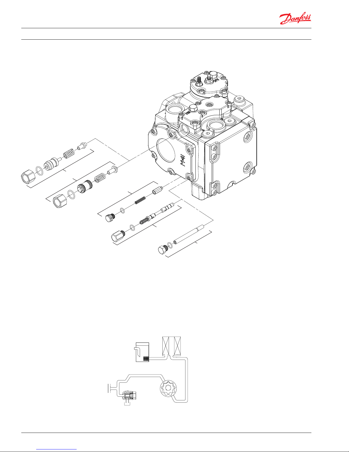
Charge relief valve
You may remove the charge relief valve for cleaning and installation of new O-rings. You may change the
pressure setting, however, note that the setting will vary for different charge flows depending on charge
pump size and pump speed. The factory setting is set relative to a specific charge flow at 120°F and 1800
min-1 (rpm) input speed. The actual charge pressure varies at different speeds.
Shim adjustable style (pre-blockpoint change)
On units manufactured prior to the 1998 block point change, you adjust the charge pressure relief valve
by changing the number or size of shims located behind the charge pressure relief valve spring.
1. Remove the shim adjustable charge relief valve plug (G040) from the pump housing. Remove and
discard the O-ring (G040A) from the plug.
Adjustable charge relief valve components
G040
Shim adjustable
charge relief valve plug
1 in
54-136 [40-100]
G041
Shims
G042
Spring
G043
Poppet
G040A
O-Ring
E100 016E
2. Remove shims (G041), spring (G042), and poppet (G043) from housing.
3. Inspect the poppet and mating seat in the housing for damage or foreign material.
4. Install a new O-ring (G040A) on the charge relief valve plug (G040). Reinstall the poppet (G043),
spring (G042), and shims (G041), into the pump housing. To confirm the charge relief valve setting,
measure the charge pressure at port M3. The charge pressure levels off when it reaches the relief
setting.
Pressure change per shim
Approximate pressure change Shim thickness
4 bar [58 psi] 1.25 mm [.050 in]
5. Install plug (G040). Torque to 54-136 Nm (40-100 lbf•ft).
Service Manual
Series 42 Axial Piston Closed Circuit Pumps
Minor Repair
520L0638 • Rev 0300 • July 2015 37
Page 38

Externally adjustable style
The 1998 block point change discontinued the use of the shim adjustable charge relief valve and made
the externally adjustable charge relief valve standard. The charge pressure changes by approximately 1.4
bar (20 psi) per quarter turn of the adjustable charge relief valve plug (this applies to both external and
internal hex style plugs).
1. Mark the adjustable charge relief valve plug (T039), lock nut (T041), and the pump housing prior to
removing the charge relief valve in order to approximately duplicate the charge pressure relief valve’s
original setting upon reassembly.
Externally adjustable charge relief valve components
T039
Anti-stall
adjustable charge
relief valve plug
8.5 mm
T041
Lock nut
1 / in
28 cc: 24 N•m
[18 lbf•ft]
41 cc: 40 N•m
[30 lbf•ft]
1
16
T039A
O-ring
T039
Adjustable
charge relief
valve plug
½ in
T043
Poppet
P108 128E
T042
Spring
2. Loosen the lock nut (T041) and unscrew the adjustable charge relief valve plug (T039).
3. Remove and discard the O-ring (T039A) from the adjustable charge relief valve plug (T039).
4. Remove the spring (T042) and poppet (T043) from the housing.
5. Inspect the poppet (T043) and seat within the housing for damage or foreign material. Replace as
necessary.
6. Install the poppet (T043) and spring (T042) into the housing.
7. Install a new O-ring (T039A) onto the adjustable charge relief valve plug (T039).
8. Install the adjustable charge relief valve plug (T039) and the lock nut (T041) into the housing, aligning
the marks made prior to disassembly.
9. On 28/32 cm3 models, torque the lock nut (T041) to 24 N•m [18 lbf•ft], and on 41/51 cm3 models,
torque the lock nut (T041) to 40 N•m [30 lbf•ft]. (This may cause misalignment of the original position
marks made earlier).
10. Confirm the charge relief valve setting by measuring charge pressure at the charge pressure gauge
port, (M3). The charge pressure reading should level off when the relief setting is reached.
Service Manual
Series 42 Axial Piston Closed Circuit Pumps
Minor Repair
38 520L0638 • Rev 0300 • July 2015
Page 39

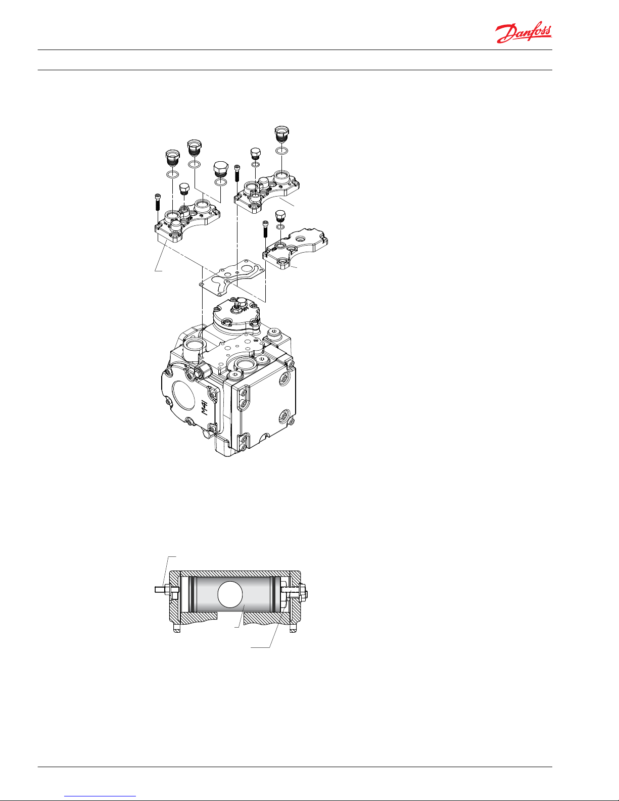
Optional speed sensor
When installing or adjusting the speed sensor on a pump, you must set it to a specific distance from the
speed ring on the cylinder block.
Removal
1. Loosen the lock nut using a 1-1/16 in hex wrench.
2. Unthread the speed sensor (N002) from the pump housing. Remove and discard the O-ring (N002A).
Speed sensor replacement
P108 081E
1-1/16 in
13 N•m
[10 lbf•ft]
11/16 in
37 N•m
[27 lbf•ft]
N002 O-ring plug
N002
N002A
N002A
Reassembly
1. Always install a new O-ring before reinstalling the sensor.
2. Reinstall the speed sensor (with lock nut and O-ring) into the housing. Turn the sensor clockwise (CW)
by hand until it contacts the speed ring.
3. Turn the sensor counterclockwise (CCW) 1/2 turn (180°) to establish the nominal gap of 0.71 mm
[0.028 inch].
Cross section view of speed sensor in variable pump
Magnetic speed ring
Speed sensor
Gap
P104 152E
Cylinder block
Service Manual
Series 42 Axial Piston Closed Circuit Pumps
Minor Repair
520L0638 • Rev 0300 • July 2015 39
Page 40

4. Then turn the sensor clockwise (CW) until the wrench flats on sensor body are positioned at a 22°
angle to the pump shaft center line.
Most adjustable wrenches have a 22° handle offset.
5. The final sensor position should be between 1/2 (180°) and 1/4 turn (90°) counterclockwise (CCW)
from the point where the sensor contacts the speed ring.
Positioning speed sensor relative to pump shaft
1/2 inch wrench flats
22°
Speed sensor with
packard connector
22°
Speed sensor with
turck connector
1/2 inch wrench flats
22°
Speed sensor with
packard connector
22°
Speed sensor with
turck connector
Shaft centerline
Shaft centerline
P104 155E
6. Hold sensor in position with a 1/2 inch hex wrench while tightening the lock nut to 13 N•m [10 lbf•ft].
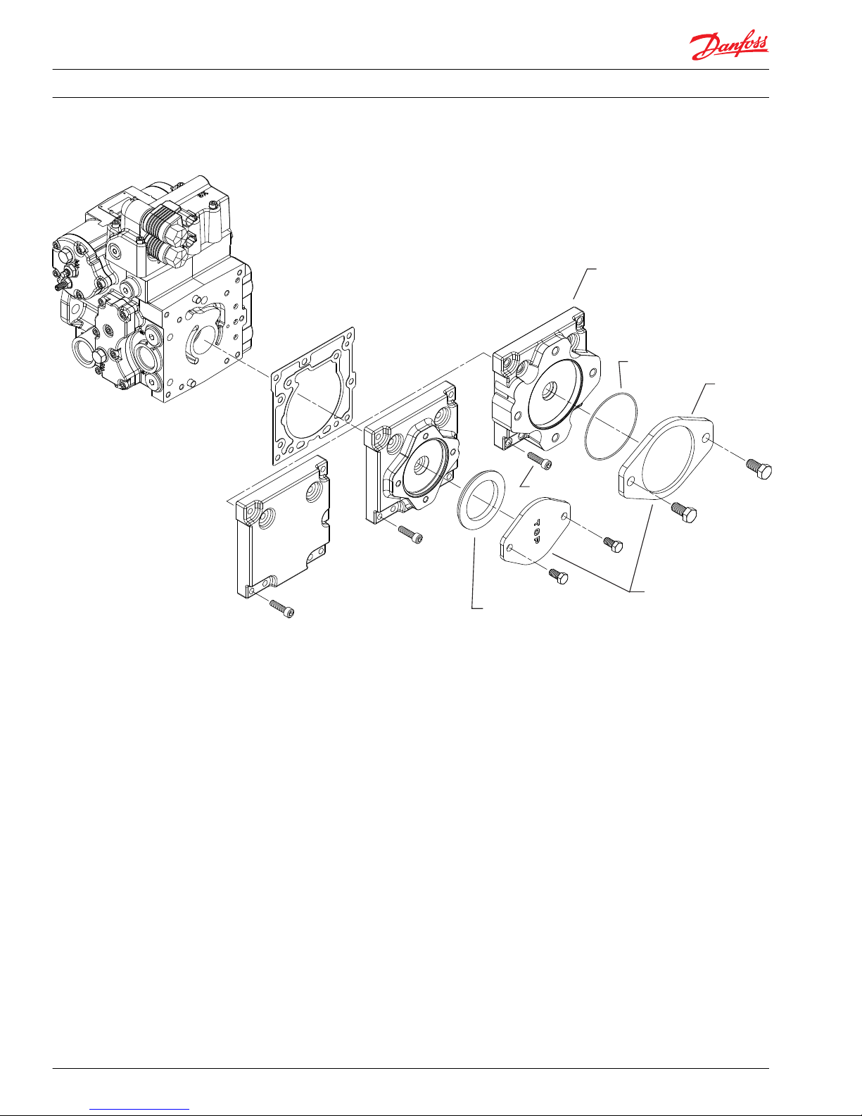
MDC Module
Removal
The manual displacement control (MDC) actuates the control spool through a connection to the
summing link pin. The following procedure describes how to remove and install the control. Control
spool and linkage removal is explained on pages 39 and 40.
1. Clean external surfaces of the pump. If necessary, remove the MDC handle (D017) and disconnect NSS
wiring (D040).
2. Being careful not to lose the backlash spring (D91), remove the control spool plugs (D032 and D035).
3. Remove the seven (7) control bolts (D002) that secure the control to the pump housing. Remove the
control (D070) and gasket (E001) from the pump. Discard the gasket.
4. Ensure that the housing and control surfaces are clean and free of gasket material. If necessary, clean
the surfaces with solvent.
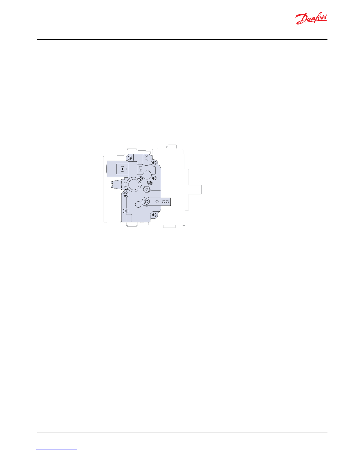
Installation
1. Place a new gasket (E001) on the control module
The control gasket acts as regulating orifices. Check the Parts Manual (28 cm3, 520L0590; or 41 cm3,
520L0589) and your order code to confirm you have the correct control gasket.
W
Warning
Unintended vehicle/machine movement hazard. MDC must be aligned to the housing within 0.005
inch. Inaccurate alignment may cause neutral to be off center or make it impossible to set.
Service Manual
Series 42 Axial Piston Closed Circuit Pumps
Minor Repair
40 520L0638 • Rev 0300 • July 2015
Page 41

For exact positioning, place the MDC alignment tool (see dimensioned diagram , next page) over the
exposed summing link pin. If MDC alignment tool is not available, skip to MDC alignment without tool
(steps 3a-5a).
2. Slide the MDC (D070) over the tool while engaging the tool with the slot in the MDC cam, and allow it
to pass through the hole on the front of the MDC housing.
Link pin into cam slot
Summing link
pin (D011)
MUST enter
the slot in the
control cam
MDC module assembly
D017
D016
D019
D002
T-30
17 N•m
[13 lbf•ft]
D040
E001
D003
/ in
13 N•m
[9.5 lbf•ft]
3
16
D070
D91
D032
D032A
D035A
D035
P108 087E
5 mm
D040A
7/8 in
70 N•m
[52 lbf•ft]
5/16 in
70 N•m
[52 lbf•ft]
3. Install the control screws (D002) and torque to 15-18 N•m [11-13 lbf•ft].
Service Manual
Series 42 Axial Piston Closed Circuit Pumps
Minor Repair
520L0638 • Rev 0300 • July 2015 41
Page 42

4. Remove the alignment tool and install plug (D003); torque to 17 N•m [13 lbf•ft].
5. Replace the spring (D91) and spool plugs (D032 and D035).
6. Adjust control neutral (see Control neutral adjustment for MDC and EDC/HC-EDC on page 33).
MDC alignment without tool.
If the MDC alignment tool is not available, it is possible to locate the approximate position of the pin by
creating an imaginary circle at the correct location, as indicated in the illustration. The point at which the
imaginary circle contacts the slot in the cam is the suggested contact point of the summing link pin.
When engaging the pin in the cam slot, you may need to use a flat tool, such as a screwdriver, to position
the linkage.
MDC cam
Point of
contact
Summing
link pin
Imaginary circle
MDC cam
For proper control operation, the summing link must engage the slot on the control module. For exact
placement, use the alignment tool shown.
MDC alignment tool
16 mm
[0.63 in]
~ 100 mm
[3.94 in]
20 mm
[0.79 in]
5.06 mm Ø
[0.1992 in +0.002]
+0.05
6.97 mm Ø
[0.2744 in -0.002]
-0.05
6 mm Ø
[0.236 in]
MACHINED FROM MILD STEEL
3a. Install and hand-tighten the seven (7) control retaining screws and then back off each screw one turn.
Torque patterns (MDC, EDC and HC-EDC)
4
3
6
1
8 Torque this bolt
first & last
7
2
5
TORQUE BOLTS IN ORDER INDICATED
P108 082E
Service Manual
Series 42 Axial Piston Closed Circuit Pumps
Minor Repair
42 520L0638 • Rev 0300 • July 2015
Page 43

4a. Adjust the control position so that the summing link pin is aligned as described above, and torque
bolts (D002) to 17 N•m [13 lbf•ft].
5a. Replace the cover plug (D003) and torque to 13 N•m [9.5 lbf•ft].
Continue above to step 6.
HC-EDC and EDC Module
The High Current Electric Displacement Control (HC-EDC) and the Electric Displacement Control (EDC)
actuate the control spool via a connection to the summing link pin. The following procedure describes
how to remove and replace the control housing.
Removal
1. Clean the external surfaces of the pump. If necessary, remove control input.
2. Being careful not to lose the backlash spring (D91), remove the control spool plugs (D032 and D035).
3. Remove the seven (7) control bolts (D081/D082). Note the position of the different length screws.
Remove the control and control gasket (E001) from the pump.
EDC module assembly
D081
T-30
17 N•m
[13 lbf•ft]
E001
Summing
link pin (D011)
MUST enter
the hole in the
control slider
block
D082
T-30
17 N•m
[13 lbf•ft]
Hold D011
(and D090)
in position
D91
D032
D032A
D035
D035A
P108 085E
5 mm
5 mm
7/8 in
70 N•m
[52 lbf•ft]
5/16 in
70 N•m
[52 lbf•ft]
Service Manual Series 42 Axial Piston Closed Circuit Pumps
Minor Repair
520L0638 • Rev 0300 • July 2015 43
Page 44

Replacement
1. Clean the sealing surfaces of the control and the pump housing. Place a new gasket (E001) in position
on the housing.
The control orifices are part of the control gasket. Refer to the appropriate Service Parts List to
determine the correct gasket.
2. Hold the summing link pin (D011) in position while installing the control. The link pin MUST engage
the hole in the control slider block (see diagram on previous page).
W
Warning
Failure to properly engage the summing link pin with control slider block will result in incorrect
control operation, which may lead to loss of control of the vehicle / machine.
Lay the servo piston side of the control down first, then watch the link pin engage from the charge
pump side of the pump.
3. Install the control bolts (D081/D082), torque to 17 N•m [13 lbf•ft].
Torque patterns (MDC, EDC and HC-EDC)
4
3
6
1
8 Torque this bolt
first & last
7
2
5
TORQUE BOLTS IN ORDER INDICATED
P108 082E
4. Replace the spring (D91). Install new O-rings on control spool plugs (D032 and D035). Install plugs
and torque to 70 N•m [52 lbf•ft].
5. Adjust the neutral position of the control as shown in Control neutral adjustment for MDC and EDC/HC-
EDC on page 33.
MDC/EDC Spool, linkage, and neutral adjustment screw
You may remove the control spool, control linkage, and control neutral adjustment screw for cleaning
and to change the O-rings or the seal lock nut.
Removal
1. Clean the external surfaces of the pump.
2. Remove the MDC, EDC or HC-EDC module and the control gasket from the pump housing. Discard
gasket. See pages 35 through 38 for control removal procedure.
3. Remove the summing link (D011). Note the manner in which the parts are assembled and the way the
summing link engages the control spool (D090).
Remove the summing link by sliding it off the feedback link.
Service Manual
Series 42 Axial Piston Closed Circuit Pumps
Minor Repair
44 520L0638 • Rev 0300 • July 2015
Page 45

MDC/EDC/HC-EDC spool and linkage
F035
F034
P036
T-30
16 N•m
[12 lbf•ft]
D011
D010
4 mm
11 N•m
[8 lbf•ft]
D012
D013
D014
5 mm
D015
17 mm
D90
D91
D090
D032
7/8 in
70 N•m
[52 lbf•ft]
D035
/ in
5
16
P108 086E
70 N•m
[52 lbf•ft]
4. Using a 4mm internal hex wrench, remove the summing link pivot pin (D010). Slide the feedback link
(D012) towards the servo piston to disengage the neutral adjustment link (D013). You can now
remove all linkages.
5. Remove the two bore plugs (D032 and D035). Note the orientation of the control spool (D90) and
which side of the pump the spring (D91) is located (spring is on the opposite side from the filter
adapter). Remove spring and spool.
Prior to the 1998 block point change, the full-featured 28 cm3 housing for the Series 42 pump used a
control spool cover (F035), gasket (F034), and two screws (F036) instead of a bore plug on the control
spool’s non-spring side. Discard the control gasket (F034) and thoroughly clean the mating surface.
6. Remove the control neutral adjustment seal nut (D015) and screw (D014).
Installation
1. Install the control neutral adjustment screw (D014) and seal lock nut (D015). Do not tighten the nut.
2. Lubricate and install the control spool (D90) and spring (D91), noting proper orientation. Install the
two side bore plugs and torque to 70 N•m [52 lbf•ft].
3. Replace the summing link, feedback link, and neutral adjustment link.
First combine the center pin of the feedback link (D012) with the mating bore of the neutral
adjustment link (D013). Insert the end of the feedback link into the servo piston slot. Mate the neutral
adjustment link with the control neutral adjustment screw (D014). Insert the linkage pivot screw
Service Manual
Series 42 Axial Piston Closed Circuit Pumps
Minor Repair
520L0638 • Rev 0300 • July 2015 45
Page 46

(D010) and torque to 11 N•m [8 lbf•ft]. Install the summing link (D011). It may be necessary to rotate
the control spool so that the summing link fork engages the flats on the control spool.
4. Install the MDC, EDC or HC-EDC according to procedures on pages 35 through 38.
Servo piston linkage and control spool
Feedback link (D012) must
enter slot in servo piston
D010
4 mm Internal hex nut
Slot in neutral adjust link
(D013) must engage groove
in adjusting screw (D014)
Fork on summing link
(D011) must engage flats
on control spool (D090
D091
Backlash spring
D090
Control
spool
Internal parts shown with housing removed
MDC Neutral start / backup alarm switch
The Neutral Start Switch (NSS) prevents the engine and pump from starting when the pump control
handle is not in neutral. The NSS should be wired in series with the engine starting circuit. The switch
contact is closed at the control handle’s neutral position and opens when the control handle is rotated
1.5° to 2° from neutral.
The Backup Alarm Switch (BAS) closes when the control handle is in a reverse position. This switch is
normally wired in series with a backup alarm. The switch contact is open until the control handle is
rotated 2.6° to 3.75° in the reverse direction.
W
Warning
The control handle’s neutral position must conform to the pump’s neutral position for the NSS/BAS to
work effectively. See Control neutral adjustment for MDC and EDC/HC-EDC on page 33 for control neutral
adjustment.
Service Manual
Series 42 Axial Piston Closed Circuit Pumps
Minor Repair
46 520L0638 • Rev 0300 • July 2015
Page 47

Top view of NSS showing NSS cam positions
III. NSSWITH BAS
(CCW = REVERSE)
Control
cam
I. NSS ONLY II. NSS WITH BAS
(CW = REVERSE)
Yoke
Control
cam
Yoke
Control
cam
Yoke
NSS cam
NSS cam
You can configure the NSS/BAS assembly for three different settings:
I. NSS only.
II. NSS with BAS for units where clockwise (CW) handle rotation results in reverse motion.
III. NSS with BAS for units where counterclockwise (CCW) handle rotation results in reverse motion.
The setting must be in accordance with the configuration of the unit. See the model code if uncertain of
the type of NSS setting the machine is equipped with.
Adjustment is normally not required unless the function of the NSS is changed (between I, II, or III).
Adjustment of the NSS or NSS and BAS requires a special alignment tool. Dimensions appear at right. The
tool positions the cam precisely relative to the control housing.
Alignment tool
Knurl
2.000
0.354
1.250
0.306
Ø 0.236 -0.030
R 0.125
9/16 -18 UNF 2A thread
35.0
0.04 x 45°
chamfer
Material: 0.75 Ø x 3 ETD150
(All dimensions in inches)
Service Manual
Series 42 Axial Piston Closed Circuit Pumps
Minor Repair
520L0638 • Rev 0300 • July 2015 47
Page 48

1. Remove the MDC module from the pump housing.
Side view of NSS and NSS cavity
D039
D037
D040
/ i n
27 N•m
[20 lbf•ft]
7
8
1 mm
[0.04 in]
23.3 mm
[0.916 in]
D038
8 mm
6 N•m
[4.4 lbf•ft]
2. Using a 7/8 in hex wrench, remove the NSS/BAS (D040).
3. Using a screwdriver to pry it out, remove and discard the NSS cover (D039). Be careful not to damage
the internal hardware.
4. Using an 8mm hex socket, remove the nut (D038).
5. Pry the cam (D037) off the shaft.
6. On the underside of the MDC module, gently clamp a pair of locking pliers around the spring contacts
of the control cam. Be careful not to damage the spring wires. The pliers hold the nub on the control
cam to the pin underneath. This holds the control cam in neutral position.
Apply locking pliers here.
Service Manual
Series 42 Axial Piston Closed Circuit Pumps
Minor Repair
48 520L0638 • Rev 0300 • July 2015
Page 49

7. Set the NSS cam (D037) in the proper orientation (I, II, or III). See the illustration on previous page.
NSS assembly on MDC
D039
D038
D037
NSS Cavity
D040
(with screw
terminals)
D040
(with weatherpack
connector)
P108 088E
8. Thread the alignment tool into the NSS cavity to hold the cam in place.
9. Install the nut (D038) onto the cam and torque to 6 N•m [4.4 lbf•ft].
10. Using an appropriate press, press a new cover (D039) into the cam cavity. Use a tool with a diameter
of 23.3 mm [0.916 in]. Press the new cover so that it sits 1 mm [0.04 in] below the cast surface as
illustrated above.
11. Remove the alignment tool and locking pliers.
12. Lubricate and install a new O-ring on the NSS (D040) and install the NSS to the MDC. Torque to 27
N•m [20 lbf•ft].
13. Reinstall the MDC module onto the pump housing as shown on pages 35 and 36.
MDC Solenoid override valve
The solenoid override valve is a safety feature that shunts both ends of the servo control piston when the
solenoid is de-energized. The pump will stroke only when the vehicle controls energize the solenoid.
The solenoid override with brake release option allows hydraulic control of a spring-applied,
hydraulically-released brake. When de-energized, the brake drains through port X7.
Service Manual
Series 42 Axial Piston Closed Circuit Pumps
Minor Repair
520L0638 • Rev 0300 • July 2015 49
Page 50

Solenoid override assembly
D056
D056A
D056D
D056
D056C
D056F
D056G
D056B
/ in
6 N•m
[4.4 lbf•ft]
3
4
D054
D053
Port
X7
P108 099E
Removal
1. Using a 3/4 inch wrench, remove the coil nut (D056B) from the valve stem.
2. Remove the coil (D056) and washer (D056C).
3. Using snap-ring pliers, remove the retaining ring (D054) at the base of the solenoid.
4. Remove the valve stem (D056D), plunger (D056G), spring (D056F), and spool (D053).
5. Remove the O-ring (D056A) from the stem, and discard it.
Installation
1. Lubricate and install a new O-ring (D056A) on the valve stem (D056D).
2. Place the spring (D056F) and the plunger (D056G) inside of the stem.
3. Attach the spool (D053) to the plunger (D056G).
4. Insert the solenoid/spool assembly into the solenoid override cavity.
5. Using snap-ring pliers, install the retaining ring (D054).
6. Install the washer (D056C) onto the valve stem.
7. Install the coil (D056) and coil nut (D056B) and torque to 6 N•m [4.4 lbf•ft]. Do not over torque coil nut.
Service Manual
Series 42 Axial Piston Closed Circuit Pumps
Minor Repair
50 520L0638 • Rev 0300 • July 2015
Page 51

FNR, NFPE, and NFPH Controls (bolt-on valves)
The FNR, NFPE, and NFPH are non-feedback type controls. The FNR and NFPE controls consist of external,
solenoid-actuated spool valves mounted on the pump housing. The pump receives hydraulic input for
NFPH through ports on the pump’s control surface (9/16–18 SAE O-ring boss port). These ports connect
directly to the servo piston.
You may remove the FNR and NFPE controls to clean the ports and replace the O-rings, however, the
controls are not serviceable. The gasket (E074) contains control orifices. Orifice plugs for NFPH pumps are
beneath the servo covers.
FNR and NFPE assembly (bolt-on valves)
E074
D004
D081
4 mm
7 N•m
[5 lbf•ft]
D004A
E074
P108 100E
41/51cc
Frame Size
Removal of FNR and NFPE modules (bolt-on valves)
1. Clean the pump and control housings.
2. Remove the four (4) screws (D081) retaining the module to the housing, and remove the module
(D004) from the pump housing.
3. Remove and discard the four O-rings (D004A). Examine the ports for cleanliness.
Service Manual
Series 42 Axial Piston Closed Circuit Pumps
Minor Repair
520L0638 • Rev 0300 • July 2015 51
Page 52

Installation of FNR and NFPE modules (bolt-on valves)
1. Clean the sealing surfaces. Install new gasket (E074).
2. Using petroleum jelly to retain them, install new O-rings (D004A) in the bottom of the control.
3. Replace the bolts (D081) and torque to 7 N•m [5 lbf•ft]. (neutral adjust bolt side).
Bolt torque patterns
1
2
3
4
Torque bolts in order indicated
3
2
4
1
P101 580E
FNR, NFPE, and NFPH Controls (integral valves)
The FNR, and NFPE are non-feedback type controls. The FNR and NFPE controls consist of solenoidactuated spool valves mounted on the pump housing.
You may remove the valves to clean the ports and replace the O-rings, however, the valves are not
serviceable.
FNR and NFPE assembly (integral valves)
P108 123E
D061
D062
D060
D061
D062
D064
D063
D060
includes
D063
and D064
7 N•m
[5 lbf•ft]
3/4 inch
30 N•m
[22.5 lbf•ft]
7/8 inch
30 N•m
[22.5 lbf•ft]
1 inch
3.4 N•m
[2.5 lbf•ft]
3/4 inch
D099
Removal of FNR and NFPE modules (integral valve style)
1. Clean the pump and control housings.
2. Remove the coil nuts (D062) and coils (D061). Discard O-rings (D063 and D064) from NFPE coils
3. Remove valve actuater stems (D060) and discard O-rings.
4. Examine the ports for cleanliness.
Service Manual
Series 42 Axial Piston Closed Circuit Pumps
Minor Repair
52 520L0638 • Rev 0300 • July 2015
Page 53

Installation of FNR and NFPE modules (integral valve style)
1. Clean the valves and ports.
2. Install new O-rings on valve actuator stems (D060).
3. Install actuator stems (D060) and torque to 30.5 N•m [22.5 lbf•ft].
4. Install coil (D061). Use new O-rings (D063 and D064) with NFPE coils.
5. Torque coil nut per illustration.
System Check Relief (SCR) valves (high pressure relief, charge check, and bypass valves)
The System Check Relief valve assembly performs the charge check, high pressure relief, and loop bypass
functions. You may remove this assembly for cleaning and replacement of O-rings. The model code
specifies which configuration of SCR valves your pump uses.
System check relief valve components
K007
/ m m
70 N•m
[52 lbf•ft
]
5
16
K008
K009
K010
H005
J005
K007
1 inch
70 N•m
[52 lbf•ft]
K008
K009
K010
WITHOUT
BYPASS
WITH
BYPASS
P108 089E
1. Using a 1 inch wrench or a 5/16 inch internal hex wrench, remove the valve seat plugs (K007) from
the pump housing. Remove and discard the O-rings and backup rings (K008, K009, and K010).
2. Remove the check poppet/relief valve assemblies (H05/J05) from the pump housing.
3. Inspect the valves and mating seats in the valve seat plugs (K007) for damage or foreign material.
The SCR valves (H005/J005) are non-serviceable; replace as a complete unit.
Service Manual
Series 42 Axial Piston Closed Circuit Pumps
Minor Repair
520L0638 • Rev 0300 • July 2015 53
Page 54

4. Install new outer O-ring (K008), backup ring (K009), and inner O-ring (K010) on each valve seat plug.
5. Verify that the conical springs are properly retained on the check poppets/relief valves (H005/J005).
Install the check poppet/relief valve assemblies into the pump housing. Ensure that the valve
assembly moves freely in its bore.
6. Using a 1 inch wrench or a 5/16 inch internal hex wrench, install the valve seat plugs or valve seat/
bypass plugs into the pump housing and torque to 70 N•m [52 lbf•ft].
Filtration adapters
Filter-related pump hardware
Filtration systems for Series 42 pump include full flow suction filtration, pressure filtration, and partial
flow pressure filtration. Danfoss provides a filtration adapter for each configuration. If filtration is
provided elsewhere in the hydraulic circuit, the pump may not have a filtration adapter.
Pumps housings without filtration adapters have an unused and plugged construction bore next to the
charge relief valve. When these pumps use suction filtration, the factory plugs external charge inlet.
Pump housings with filtration adapters have an appropriate adapter and gasket. The position of the M3
gauge port varries depending on filtration type.
Pumps manufactured after 1998 have filter adapter screws that are 10 mm [0.39 in] longer than the
screws used on pre-1998 pumps. The longer screws are only compatible with post-1998 pumps.
Housing with filtration adapter
R042 (x7)
17 N•m
[13 lbf•ft]
R043
R040
R041
T30
37 N•m
[27 lbf•ft]
Pre 1998: 7/8 in
Post 1998: 11/16 in
P108 090E
5 mm
Service Manual Series 42 Axial Piston Closed Circuit Pumps
Minor Repair
54 520L0638 • Rev 0300 • July 2015
Page 55

Removal
1. Clean the exterior of the pump.
2. Remove any hoses or piping from the filter adapter.
3. Using a T30 Torx driver or 5 mm internal hex, remove the six screws (R042) securing the filter adapter
to the housing.
4. Remove the filter adapter (R040).
Housing without filtration adapter
R045
G004
5/8 in
37 N•m
[27 lbf•ft]
P108 091E
Suction Filtration Only
5. Remove the gasket (R041) and discard. Thoroughly clean all mating surfaces.
Replacement
1. Install a new gasket (R041) and place the filter adapter (R040) on the housing.
2. Using a T30 Torx driver or 5 mm internal hex, install bolts (R042) and torque to 17 N•m [13 lbf•ft].
Bolt torque patterns
1
2
3
4
5
6
7
8
Torque this bolt
first and last
TORQUE BOLTS IN THE ORDER INDICATED
Auxiliary pad/charge pump cover
Use the following procedure to install a new gasket (U030) or to change the auxiliary pad option. Pads are
available for SAE A and SAE B auxiliary pumps, or for options with no auxiliary pad.
The charge pump cover integrates the auxiliary mounting pad. When no auxiliary pump is present on an
SAE A or SAE B style pad, the pad includes a shipping plate (U085) and O-ring (U080).
Service Manual
Series 42 Axial Piston Closed Circuit Pumps
Minor Repair
520L0638 • Rev 0300 • July 2015 55
Page 56

Auxiliary pad options
U040
No pad charge
pump co
ver
U035 (x8)
45 N•m
[33 lbf•ft]
U040
SAE-A pad
U040
SAE-B pad
U080
U035
U080
U035
G023
U030
U090
/ in
100 N•m
[74 lbf•ft]
3
4
U085
U085
U090
/ in
42 N•m
[31 lbf•ft]
9
16
P108 103E
6 mm
(x8)
(x8)
Removal of charge pump cover/auxiliary pad
1. Orient the pump so that the charge pump cover or pad (U040) is facing up.
2. If present, remove the auxiliary pump or cover (U085) by removing the two screws (U090). Discard the
O-ring (U080).
3. Remove screws (U035) retaining the charge pump cover/pad. Remove the charge pump cover/pad
(U040) and gasket (U030). You may reuse the gasket. Clean all mating surfaces.
4. Remove and discard charge pump seal (G023). Leave alignment pins in the housing.
Installation
1. Inspect the charge pump cover/pad gasket (U030) and mating surfaces. If undamaged, you may reuse
the gasket. Replace the gasket if you suspect leakage. Install the gasket.
2. Install a new charge pump cover/pad seal (G023).
3. Install the charge pump cover/pad (U040) Using a 6 mm internal hex torque the six or seven bolts
(U035) to 45 N•m [33 lbf•ft] using the pattern at the right.
4. Replace the O-ring (U080) and cover plate (U085) or auxiliary pump. Install and torque the two
mounting screws (U090). For SAE A pads, torque the mounting screws to 42 N•m [31 lbf•ft]. For SAE B
pads, torque the mounting screws to 100 N•m [74 lbf•ft].
The threaded screw holes in the auxiliary pump mounting pad in early production pumps with the
SAE A pad option go clear through the charge pump cover. Use M8x1.25 internal hex set-screws to
plug any holes not used to attach the cover plate or auxiliary pump. Install hand tight to prevent the
entrance of foreign material into the pump.
Service Manual
Series 42 Axial Piston Closed Circuit Pumps
Minor Repair
56 520L0638 • Rev 0300 • July 2015
Page 57

Bolt torque patterns
1
2
3
4
5
7
9
Torque this bolt first and last.
TORQUE BOLTS IN ORDER INDICATED
1
2
3
4
5
6
7
9
Torque this bolt first and last
P108 083E
6
8
8
Charge pump
You may disassemble the charge pump to inspect, clean, or to change the auxiliary shaft drive coupling
(U015). Post 1998 pumps contain a number of non-interchangeable parts within the charge pump
system:
•
Pre-1998 pumps have a gerotor drive coupling with a drive pin for the gerotor element, while post
1998 release pumps will contain a coupling with a parallel drive key. This change also results in a
change to the gerotor set. When servicing the gerotor, these two elements must be placed in
combination. A service kit is available for pre-1998 charge pumps. Refer to service bulletin 1997-029.
•
Post 1998 release pumps also contain a coupling with a retaining ring to positively locate the
coupling in the assembly. This change eliminated the need for a coupling spacer.
•
The outer step on the gerotor cover has been removed on the post 1998 release pumps.
Service Manual
Series 42 Axial Piston Closed Circuit Pumps
Minor Repair
520L0638 • Rev 0300 • July 2015 57
Page 58

Charge pump components
G023
G020
G015
U015
G006
G005
Keyway
G010
G065
Use feeler
gauge
U025
U025
P108 092E
Disassembly
1. Remove alignment pins (U025)
2. Remove the gerotor cover assembly (G020). Remove and discard gerotor cover O-ring (G023) (early
production SAE A pad models may contain two or three seals: only the inner G023 seal is required).
3. Remove the drive coupling (U015) and gerotor gear set (G010). Remove retaining ring (G006).
4. Remove the gerotor drive pin or key (G005). Remove the gerotor cover locating pin (G065).
5. Inspect the gerotor assembly (G010). Ensure the upper and lower surfaces of the gerotor are free of
nicks and grooves. The mating surfaces of the inner and outer gears should fit snugly and create a
tight seal. Inspect the keyway for major wear. It is normal to find a small impression from the drive pin
(G005). Measure gerotor tip clearance for wear (illustrated above). Seat the gerotor assembly into the
gerotor cover and align the assembly so that one of the tips of the inner gear fully engages a valley in
the outer gear. Using a feeler gauge, measure the clearance of the opposite tip. Clearance should be
0.127 mm [0.005 inch] or less. Replace the gerotor if necessary. The gerotor assembly is machined as a
matched pair.
6. Inspect the drive pin or key (G005) to ensure that the edges are not rounded and that the drive
coupling’s internal splines are straight and free of damage on both ends. Check for wear on the top
and bottom surfaces. Replace the drive pin or key if worn.
7. Inspect the gerotor cover (G020). It should be free of nicks and scratches. The drive coupling journal
bearing (G015) is on the inside diameter of the small bore of the aluminum gerotor cover. The drive
Service Manual
Series 42 Axial Piston Closed Circuit Pumps
Minor Repair
58 520L0638 • Rev 0300 • July 2015
Page 59

coupling should fit the journal bearing with a relatively close fit. If the coupling has worn through the
bearing and into the aluminum gerotor cover, replace the gerotor cover and drive coupling. If the fit
is excessively loose and the drive coupling has not worn into the gerotor cover, remove the old
journal bearing from the gerotor cover and press a new journal bearing into the cover from the cavity
side. Press the bearing to a depth of 12.88 mm [0.507 in] from the bottom (cavity side) of the gerotor
cover.
Assembly
1. Install the two charge pump cover/pad alignment pins (U025).
2. Install the gerotor cover locating pin (G065).
3. Install the 41 cm3 spacer (not shown) if previously removed. (Spacers exist on the older 41 cm3
models.)
4. Install the drive pin or key (G005) into the drive coupling. Use petroleum jelly to hold it in place.
5. Lubricate and install the gerotor set (G010) onto the drive coupling (U015). Align the notch in the
inner gear with the drive pin or key (G005).
6. If present, install the retaining ring (G006) onto the drive coupling.
7. With the smaller end of the drive coupling (U015) facing up, install the drive coupling and gerotor
onto the shaft.
Different drive couplings are used with different charge pump covers.
8. Place the gerotor cover assembly (G020/G015) over the gerotor assembly and rotate until the cover
engages the orientation pin. The cover fits flat.
9. Lubricate the new gerotor cover O-ring (G023) with petroleum jelly and place it on the gerotor cover
(G020). Early production A pad models may contain two or three seals.
10. Install the charge pump cover gasket, charge pump cover, and auxiliary pump
Charge pump orientation looking inside of gerotor pump cover
CW CCW
12.88 mm
[0.507 in]
G020
G015
Units without integral charge pump
Variable pumps without an integral charge pump have a spacer (G010) in the location where the gerotor
assembly goes. A plug (N004) blocks the charge pump inlet port. Pumps without an integral charge
pump that are not machined to accept a filtration adapter, contain a charge pump defeat plug (R020) in
the gerotor cavity outlet. An O-ring (R020A) holds this plug in place. Later models have an M6 thread in
the exposed end of the plug for easier removal. Replace the O-ring when removing the plug.
Pumps without an integral charge pump that are machined to accept a filtration adapter, do not contain
a charge pump defeat plug. Pumps in this configuration use a full-flow pressure filtration adapter with a
steel O-ring plug (R086) in the charge flow outlet port. The suction filtration adapter does not suit this
configuration; neither does the partial-flow pressure filtration adapter. It bypasses the charge relief valve.
Service Manual
Series 42 Axial Piston Closed Circuit Pumps
Minor Repair
520L0638 • Rev 0300 • July 2015 59
Page 60

No charge pump option components
R020
G023
G020
G010
U015
G006
R020A
G004
Charge inlet
Charge inlet
G004
R086
To filter
P108 093E
Housing with filtration adapter (left)
Housing without filtration adapter (right)
Servo piston covers and NFPH control orifice
You can remove the servo piston covers to change the gasket or to inspect/change the NFPH control
orifices.
Service Manual
Series 42 Axial Piston Closed Circuit Pumps
Minor Repair
60 520L0638 • Rev 0300 • July 2015
Page 61

Servo piston cover components
E051
NFPH orific
e
3 mm
3 N•m
E052
NFPH orific
e
3 mm
3 N•m
[2.2 lbf•ft]
[2.2 lbf•ft]
P108 104E
L002
L001
(non-feedback
controls only)
L001
T060
Locknut
see table
T060
Locknut
see table
M001
M002
M005
17 N•m
[13 lbf•ft]
T30
5 mm
L005
T30
5 mm
L005
T30
5 mm
17 N•m
[13 lbf•ft]
17 N•m
[13 lbf•ft]
T015
Frame size cm
3
28/32 41/51
Control MDC/EDC/HC-EDC NFPE/NFPH MDC/EDC/HC-EDC NFPE/NFPH
Lock nut 13 mm 17 mm 17 mm 17 mm
Servo adjust screw 5 mm 7 mm 7 mm 7 mm
Disassembly
1. Remove locknut (T060) from the right side servo cover.
2. Using a T-30 Torx driver or 5 mm internal hex, remove the servo cover bolts (M005). Post 1998 release
pumps have cover bolts that are 10 mm [0.39 in] longer than pre-1998 pumps. The longer bolts are
only compatible with post-1998 pump housing.
3. Remove the servo piston covers (L001/M001).
To remove the right side servo cover turn the neutral adjustment screw (T015) clockwise (inward) far
enough for the servo cover to clear the nearby case drain port. Then pull the cover away from the
housing and turn the cover counterclockwise to remove it from the adjustment screw.
4. Remove the gaskets (L002/M002). Clean gasket surfaces.
5. NFPH control orifice plugs (E051 and E052) are located beneath the servo covers. If necessary, remove
and clean the orifices.
Service Manual
Series 42 Axial Piston Closed Circuit Pumps
Minor Repair
520L0638 • Rev 0300 • July 2015 61
Page 62

Assembly
1. Replace the NFPH control orifice plugs (E0 51, E052) if they were removed.
2. Install new gaskets (L002/M002).
3. On the right side, thread the servo piston cover (L001) onto the neutral adjustment screw. Then, while
holding the cover, turn the neutral adjustment screw (T015) counter-clockwise to run the cover down
the screw threads.
W
Warning
Unintended vehicle movement hazard: When you remove the right side servo piston cover, you must
set neutral and control neutral. Refer to Control neutral adjustment for MDC and EDC/HC-EDC on page
33.
4. Using a T30 Torx driver or 5 mm internal hex, install the servo piston cover screws (L005/M005).
Torque to 17 N•m [13 lbf•ft] in the pattern shown.
Bolt torque patterns
1
5
4
2
3
6
Torque this
bolt first and
last
TORQUE BOLTS IN ORDER INDICATED
5. Install a new seal lock nut (T060) onto the neutral adjustment screw (T015). Do not torque at this time.
6. Perform pump neutral adjustment and control neutral adjustment procedures. Refer to Control
neutral adjustment for MDC and EDC/HC-EDC on page 33.
Removal of the servo covers may change the position of the displacement limiters; readjust if
necessary.
Loop flushing and loop flushing relief valve
The loop flushing function consists of the loop flushing shuttle valve and the loop flushing relief valve.
You may remove the assemblies for cleaning and installation of new O-rings. You may exchange the relief
valve poppet for one with a different flow rating. Take notice, though, pre 1998 models contained relief
shims, do not change these shims unless Danfoss specifically instructs you to do so. You may also defeat
the loop flushing function by installing a defeat spool.
Series 42 pumps built prior to 1998 use unique loop flushing spools. Post 1998 release pumps use a
common loop flushing spool. They are not interchangeable.
Service Manual
Series 42 Axial Piston Closed Circuit Pumps
Minor Repair
62 520L0638 • Rev 0300 • July 2015
Page 63

Loop flushing valve and loop flushing defeat components
Q060
/ i n
27 N•m
[20 lbf•ft]
5
8
Q060A
Q061
Q062
Q050
/ i n
37 N•m
[27 lbf•ft]
11
16
Q050A
Q051
Q051
Q050A
P108 105E
Loop flushing valve
1. Remove the loop flushing plug (Q050). Discard the O-ring (Q050A).
2. Remove the loop flushing spool assembly (Q051) from the housing.
3. Inspect the parts for damage or foreign material. Ensure the washer securely retains the centering
spring.
4. Install the loop flushing valve spool assembly (Q051) into its bore. Install a new O‑ring (Q050A) on the
loop flushing plug (Q050); torque to 37 N•m [27 lbf•ft].
Loop flushing relief valve
Two styles of loop flushing relief valve plugs exist. The style of plug is depends on the charge pressure
specification. If the charge pressure is greater than or equal to 18 bar [260 psi]: the plug has two
identification grooves. If the charge pressure is less than 18 bar [260 psi]: the plug has a single
identification groove.
Service Manual
Series 42 Axial Piston Closed Circuit Pumps
Minor Repair
520L0638 • Rev 0300 • July 2015 63
Page 64

1. Remove the loop flushing relief valve plug (Q060). Discard the O-ring (Q060A).
2. Remove the spring (Q061) and poppet (Q062) from the housing.
3. Do not alter the shims between the spring and plug, or interchange parts with another valve. Inspect
the poppet and mating seat in the housing for damage or foreign material. Inspect the orifice in the
valve poppet.
4. Install a new O-ring (Q060A) on the plug (Q060). Install the poppet (Q062), spring (Q061), shims, and
plug into the pump housing, torque to 27 N•m [20 lbf•ft].
Defeating loop flushing
1. Remove the loop flushing plug (Q050). Discard the O-ring (Q050A).
2. Remove the loop flushing spool assembly (Q051) from the pump housing.
3. Install the defeat spool (Q051) into the spool bore with tapped end facing outwards. Install the
standard plug with O-ring into the housing and torque to 37 N•m [27 lbf•ft].
4. Remove the loop flushing relief plug (Q060). Discard the O-ring (Q060A).
5. Remove the loop flushing relief valve components (Q061/Q062).
6. Install the loop flushing relief plug (Q060) with a new O-ring (Q060A) into the housing and torque to
27 N•m [20 lbf•ft].
Shaft seal, roller bearing, and shaft replacement
Series 42 pumps use a lip type shaft seal. You can replace the seal and/or shaft without major
disassembly.
Shaft seal components
F096
C020
F091
see table
C017
P108 069E
Service Manual
Series 42 Axial Piston Closed Circuit Pumps
Minor Repair
64 520L0638 • Rev 0300 • July 2015
Page 65

Case Drain Plug
Frame Size 28/32 cm3 41/51 cm3
Internal Hex 9/16 in 5/8 in
Torque 120 N•m
[89 lbf•ft]
200 N•m
[150 lbf•ft]
Seal removal
1. Position the pump with the shaft facing up.
If the unit is positioned horizontally when the shaft is removed, the cylinder block could move out of
place, making shaft installation difficult.
2. Remove the case drain plug (F091) to relieve any vacuum that may be present.
3. Remove the spiral retaining ring (F096). Using a screwdriver, pry the end of the ring free and unwind
the remainder of the ring out of the groove.
4. Remove the seal carrier assembly (C020). Loosen it from the unit by prying on the raised surface of
the seal carrier with a screwdriver.
5. Removeand discard O-ring (C017).
6. Pry or press lip seal (C018) from the seal carrier (C020); use caution to avoid damaging the seal carrier.
Discard the seal.
7. Inspect the seal carrier (C020) for damage.
8. Press the new seal (C018) into the shaft bearing side of the seal carrier. Be careful to only press on the
outside diameter of the lip seal. Orient the seal as shown in the illustration. Be careful not to damage
the seal.
Installation of shaft seal
C018
C020
C017
Seal carrier shown
with the inside
facing up
Press seal to bottom of the carrier
E100 020E
Shaft removal
1. Grip the shaft assembly by the splines or keyed end and remove from the pump.
2. Inspect the shaft for damage. Ensure the shaft and splines are straight and free of damage or heavy
wear. Inspect the surface where the rear shaft bearing contacts the shaft. If spalling is present, replace
the shaft and rear shaft bearing.
Replacement of shaft rear bearing is a major repair and violates the unit’s warranty policy unless
performed by an authorized Danfoss Global Service Partner.
If necessary, clean the sealing area with a nonabrasive material. Lubricate the shaft with a light
coating of hydraulic fluid.
Service Manual
Series 42 Axial Piston Closed Circuit Pumps
Minor Repair
520L0638 • Rev 0300 • July 2015 65
Page 66

Shaft seal, roller bearing, and shaft replacement
P108 107E
C002
C003
C001
3. Inspect the shaft bearing (C003) for damage and rotate to ensure smoothness. If you suspect
contamination or damage, clean with solvent and lubricate with hydraulic fluid. Replace if necessary.
If you are not replacing the shaft or bearing, proceed with reassembly.
Shaft bearing replacement
1. Remove the retaining ring (C002) using snap ring pliers.
2. Observe the orientation of the chamfer on the bearing. Press the bearing off of the shaft.
3. Verify the chamfer on the bearing is facing toward the pump. Press the new bearing onto the shaft.
Press only on the inner race of the roller bearing.
4. Using snap-ring pliers, install the retaining ring (C002).
Service Manual
Series 42 Axial Piston Closed Circuit Pumps
Minor Repair
66 520L0638 • Rev 0300 • July 2015
Page 67

Reassembly
1. Ensure that the cylinder kit and rear bearing are aligned. Insert the shaft assembly into the pump. It
may be necessary to grip the splined end of the shaft and twist to align it with the block splines and
properly seat it into the rear bearing.
Shaft seal, roller bearing, and shaft replacement
F096
C020
F091
see table
C017
P108 069E
2. Lubricate a new O-ring (C017) with petroleum jelly and seat it into the housing, on top of the bearing.
3. Cover the end of the shaft with an assembly sleeve. Lubricate shaft seal with petroleum jelly.
4. Slide the seal carrier assembly over the shaft and into the housing. Press the seal carrier against the O-
ring. It may be necessary to use a large socket to press the seal carrier down completely.
5. Wind the spiral retaining ring (F096) into the groove in the housing.
Service Manual
Series 42 Axial Piston Closed Circuit Pumps
Minor Repair
520L0638 • Rev 0300 • July 2015 67
Page 68

Torque table
Sequence
Number
Part Description Tool Type Tool Size Torque
N•m [lbf•ft]
D002 MDC bolts Torx wrench/ Internal hex T-30/5 mm 17 [13]
D003 Cover plug Internal hex wrench 3/16 in 13 [9.5]
D010 Linkage pivot screw Internal hex wrench 4 mm 11 [8]
D015 MDC/EDC/HC-EDC neutral
adjustment seal lock nut
External hex wrench 17 mm 40 [30]
D032 Control spool bore plug External hex wrench 7/8 in 70 [52]
D035 Control spool bore plug Internal hex wrench 5/16 in 70 [52]
D038 Control nut External hex wrench 8 mm 6 [4.4]
D040 Neutral start switch External hex wrench 7/8 in 27 [20]
D056A Retaining nut External hex wrench 3/4 in 6 [4.4]
D081 FNR/NFPE bolts Internal hex wrench 4 mm 7 [5]
D081/D082 EDC/HC-EDC bolts Torx wrench/ Internal hex T-30/5 mm 17 [13]
E051 NFPH orifice Internal hex wrench 3 mm 3 [2.2]
F091 Case drain plug (28/32 cm3) Internal hex wrench 9/16 in 120 [89]
F091 Case drain plug (41/51 cm3) Internal hex wrench 5/8 in 200 [150]
F093 System gauge ports M1 and M2
plugs
External hex wrench 11/16 in 37 [27]
G040 Shim adjustable charge relief valve
plug
External hex wrench 1 in 90 [66]
K007 Valve seat plug
(with bypass)
External hex wrench 1 in 70 [52]
K007 Valve seat plug
(without bypass)
Internal hex wrench 5/16 in 70 [52]
L005/M005 Servo piston cover bolts Torx wrench/ Internal hex T-30/5 mm 17 [13]
L010/M010 Servo gauge plug External hex wrench 11/16 in 37 [27]
L025/M025 Displacement limiter seal lock nut External hex wrench 13 mm 23 [17]
N002 Port N plug External hex wrench 11/16 in 37 [27]
P036 Control spool cover screws
(pre-block point change)
Torx wrench/ Internal hex T-30/5 mm 16 [12]
Q050B Loop flushing plug
(pre-block point change)
Internal hex wrench 1/4 in 6 [4.4]
Q050B Loop flushing plug
(post-block point change)
External hex wrench 11/16 in 37 [27]
Q060B Loop flushing relief valve plug External hex wrench 5/8 in 27 [20]
R042 Filtration adapter bolts Torx wrench/ Internal hex T-30/5 mm 17 [13]
T041 Lock nut (28/32 cm3) External hex wrench 1 1/16 in 24 [18]
T041 Lock nut (41/51 cm3) External hex wrench 1 1/16 in 40 [30]
T060 Pump mechanical neutral
adjustment seal lock nut (28/32
cm3, MDC/EDC/HC-EDC)
External hex wrench 13 mm 23 [17]
T060 Pump mechanical neutral
adjustment seal lock nut (28/32
cm3, NFP control and 41/51 cm3, all
controls)
External hex wrench 17 mm 40 [30]
Service Manual Series 42 Axial Piston Closed Circuit Pumps
Appendix A - Torques
68 520L0638 • Rev 0300 • July 2015
Page 69

Sequence
Number
Part Description Tool Type Tool Size Torque
N•m [lbf•ft]
U035 Charge pump cover bolts Torx wrench/ Internal hex T-45/6 mm 45 [33]
U090 Auxiliary pump screws
(SAE-A pad)
External hex wrench 9/16 in 42 [31]
U090 Auxiliary pump screws
(SAE-B pad)
External hex wrench 3/4 in 100 [74]
Service Manual Series 42 Axial Piston Closed Circuit Pumps
Appendix A - Torques
520L0638 • Rev 0300 • July 2015 69
Page 70

Pre-block point change
Model code
Model Code
Model No. Ident Nr
Serial No. Fabr Nr
Ames, Iowa, U.S.A. Neumünster, Germany
MADE IN U.S.A.
4282051
A 97 23 67890
Serial no.
42L28 - C - ANN1 - 01 ANA - 2CNB - NN - NN - N N - N - NNN - NNN
{
X XX XX XXXXX
Location Year Week Sequence
number
Service Manual Series 42 Axial Piston Closed Circuit Pumps
Appendix B - Specification Tags
70 520L0638 • Rev 0300 • July 2015
Page 71

Post-block point change
Model-No./Ident-No.
Model Code
Serial-No.
Made in USA
Name plate (USA)
Place of manufacture
Model
number
Serial
number
Model
code
P100438E
A=Ames, IA
Specifications
tag
Model-No./Ident-No.
Model Code
Serial-No.
Made in Japan
Name plate (Japan)
Place of manufacture
Model
number
Serial
number
Model
code
P108 106E
DAIKIN
Y=Osaka, Japan
J=Osaka, Japan
Service Manual Series 42 Axial Piston Closed Circuit Pumps
Appendix B - Specification Tags
520L0638 • Rev 0300 • July 2015 71
Page 72

Pre-block point change nomenclature
• Series
• Rotation
• Frame Size
• Input Shaft
• Control
• Control Response
• Housing
• Charge Pump
• System Relief - Port A
• System Relief - Port B
• Bypass Valve
• Displacement Limiters - Side 1
• Displacement Limiters - Side 2
• Special Hardware
• Special Features
Service Manual
Series 42 Axial Piston Closed Circuit Pumps
Appendix C - Nomenclature
72 520L0638 • Rev 0300 • July 2015
Page 73

Post-block point change nomenclature
• Series
• Rotation
• Frame Size
• Input Shaft
• Control
• Control Response
• Housing
• Loop Flushing
• Filtration
• Charge Pump
• Charge Relief Setting
• Special Drive Features
• Auxiliary Mounting Pad
• System Relief - Port A
• System Relief - Port B
• Bypass Valve
• Displacement Limiters - Side 1
• Displacement Limiters - Side 2
• Special Hardware
Service Manual
Series 42 Axial Piston Closed Circuit Pumps
Appendix C - Nomenclature
520L0638 • Rev 0300 • July 2015 73
Page 74

• Special Features
Service Manual Series 42 Axial Piston Closed Circuit Pumps
Appendix C - Nomenclature
74 520L0638 • Rev 0300 • July 2015
Page 75

Service Manual Series 42 Axial Piston Closed Circuit Pumps
520L0638 • Rev 0300 • July 2015 75
Page 76

Danfoss Power Solutions is a global manufacturer and supplier of high-quality hydraulic and
electronic components. We specialize in providing state-of-the-art technology and solutions
that excel in the harsh operating conditions of the mobile off-highway market. Building on
our extensive applications expertise, we work closely with our customers to ensure
exceptional performance for a broad range of off-highway vehicles.
We help OEMs around the world speed up system development, reduce costs and bring
vehicles to market faster.
Danfoss – Your Strongest Partner in Mobile Hydraulics.
Go to www.powersolutions.danfoss.com for further product information.
Wherever off-highway vehicles are at work, so is Danfoss. We offer expert worldwide support
for our customers, ensuring the best possible solutions for outstanding performance. And
with an extensive network of Global Service Partners, we also provide comprehensive global
service for all of our components.
Please contact the Danfoss Power Solution representative nearest you.
Local address:
Danfoss
Power Solutions GmbH & Co. OHG
Krokamp 35
D-24539 Neumünster, Germany
Phone: +49 4321 871 0
Danfoss
Power Solutions ApS
Nordborgvej 81
DK-6430 Nordborg, Denmark
Phone: +45 7488 2222
Danfoss
Power Solutions (US) Company
2800 East 13th Street
Ames, IA 50010, USA
Phone: +1 515 239 6000
Danfoss
Power Solutions Trading
(Shanghai) Co., Ltd.
Building #22, No. 1000 Jin Hai Rd
Jin Qiao, Pudong New District
Shanghai, China 201206
Phone: +86 21 3418 5200
Danfoss can accept no responsibility for possible errors in catalogues, brochures and other printed material. Danfoss reserves the right to alter its products without notice. This also applies to
products already on order provided that such alterations can be made without changes being necessary in specifications already agreed.
All trademarks in this material are property of the respective companies. Danfoss and the Danfoss logotype are trademarks of Danfoss A/S. All rights reserved.
520L0638 • Rev 0300 • July 2015 www.danfoss.com
©
Danfoss A/S, 2015
Products we offer:
•
Bent Axis Motors
•
Closed Circuit Axial Piston
Pumps and Motors
•
Displays
•
Electrohydraulic Power
Steering
•
Electrohydraulics
•
Hydraulic Power Steering
•
Integrated Systems
•
Joysticks and Control
Handles
•
Microcontrollers and
Software
•
Open Circuit Axial Piston
Pumps
•
Orbital Motors
•
PLUS+1® GUIDE
•
Proportional Valves
•
Sensors
•
Steering
•
Transit Mixer Drives
Comatrol
www.comatrol.com
Schwarzmüller-Inverter
www.schwarzmuellerinverter.com
Turolla
www.turollaocg.com
Hydro-Gear
www.hydro-gear.com
Daikin-Sauer-Danfoss
www.daikin-sauer-danfoss.com
 Loading...