

Page 1
Technical Information
Series 40 Direct Displacement Pumps
powersolutions.danfoss.com
Page 2

Technical Information
Series 40 Direct Displacement Pumps
Revision history Table of revisions
Date Changed Rev
July 2017 Removed outdated images 0703
January 2017 Minor updates 0702
July 2015 Minor edits 0701
February 2015 Danfoss layout GA
Sep 2013 Change system pressure specs FB
Aug 2013 Remove M46 from manual FA
Feb 2010 Fix Osaka address EI
Jun 2009 Remove M25U outline drawing EH
Jul 2008 Add plug for Charge pressure construction port EG
Oct 2007 Identified A Pad and B Pad as M35 and M44 EF
Jul 2007 orrections to table - G factors for sample applications ED
Jun 2006 Corrections to maximum flow EC
May 2006 Added an illustration to page 21 EB
2 | © Danfoss | July 2017 520L0635 | BC00000106en-US0703
Page 3

Technical Information
Series 40 Direct Displacement Pumps
Contents
Specifications
Design Specifications......................................................................................................................................................................5
Technical Specifications.................................................................................................................................................................5
Operating Parameters.....................................................................................................................................................................5
Options.................................................................................................................................................................................................5
Fluid Specifications..........................................................................................................................................................................6
General Information
Series 40 Family of Pumps and Motors.....................................................................................................................................7
M25 Variable Pump..........................................................................................................................................................................7
M35 Variable Pump (M44 is similar)...........................................................................................................................................8
M35/44 Pump Schematic.............................................................................................................................................................. 8
Features and Options
Key Features....................................................................................................................................................................................... 9
Options.................................................................................................................................................................................................9
Operating Parameters
Fluids.................................................................................................................................................................................................. 10
Viscosity.............................................................................................................................................................................................10
Temperature.................................................................................................................................................................................... 10
Charge Pressure..............................................................................................................................................................................10
Case Pressure...................................................................................................................................................................................10
Pressure Ratings............................................................................................................................................................................. 11
Speed Ratings..................................................................................................................................................................................11
Inlet Pressure................................................................................................................................................................................... 11
Theoretical Output........................................................................................................................................................................ 12
System Design Parameters
Sizing Equations............................................................................................................................................................................. 13
Filtration............................................................................................................................................................................................ 13
Suction filtration....................................................................................................................................................................... 13
Charge filtration........................................................................................................................................................................ 14
Redundant Braking System Requirement.............................................................................................................................14
Loop Flushing..................................................................................................................................................................................15
Reservoir............................................................................................................................................................................................15
Case Drain usage for Tandem Pumps.....................................................................................................................................15
Bearing Life and External Shaft Loading ...............................................................................................................................15
Hydraulic Unit Life......................................................................................................................................................................... 16
Mounting Flange Loads...............................................................................................................................................................17
Model Code
Model Code......................................................................................................................................................................................19
Options
Charge Pump...................................................................................................................................................................................21
Charge Pump Output Flow........................................................................................................................................................ 22
Charge Pump Power Requirements........................................................................................................................................22
Charge Relief Valve........................................................................................................................................................................22
Charge Check/High Pressure Relief Valve (HPRV).............................................................................................................. 23
Auxiliary Mounting Pads and Auxiliary Pumps................................................................................................................... 24
Shaft Options...................................................................................................................................................................................26
M25 Variable Pump.......................................................................................................................................................................27
M25 Tandem Pump.......................................................................................................................................................................28
M35/44 Variable Pump................................................................................................................................................................ 29
M35/44 Tandem Pump................................................................................................................................................................ 30
Direct Displacement Control (DDC)........................................................................................................................................ 31
External control handle requirements..............................................................................................................................31
Installation Drawings
M25 Variable Pump.......................................................................................................................................................................33
M25 Tandem Pump.......................................................................................................................................................................35
©
Danfoss | July 2017 520L0635 | BC00000106en-US0703 | 3
Page 4

Technical Information
Series 40 Direct Displacement Pumps
Contents
M35/44 Variable Pump................................................................................................................................................................ 37
M35/44 Tandem Pump................................................................................................................................................................ 39
Performance Data
Performance.....................................................................................................................................................................................41
Schematics
Single Pump Schematics.............................................................................................................................................................42
Tandem Pump Schematics.........................................................................................................................................................43
4 | © Danfoss | July 2017 520L0635 | BC00000106en-US0703
Page 5
Technical Information
Series 40 Direct Displacement Pumps
Specifications
Design Specifications
Product line Series 40 Pumps
Pump type In-line, axial piston, variable, positive displacement pumps
Direction rotation Clockwise (CW) or counterclockwise (CCW) available
Installation position Discretionary, the housing must be filled with hydraulic fluid
Filtration configuration Suction or charge pressure filtration
Other system requirements Independent braking system, suitable reservoir and heat exchanger
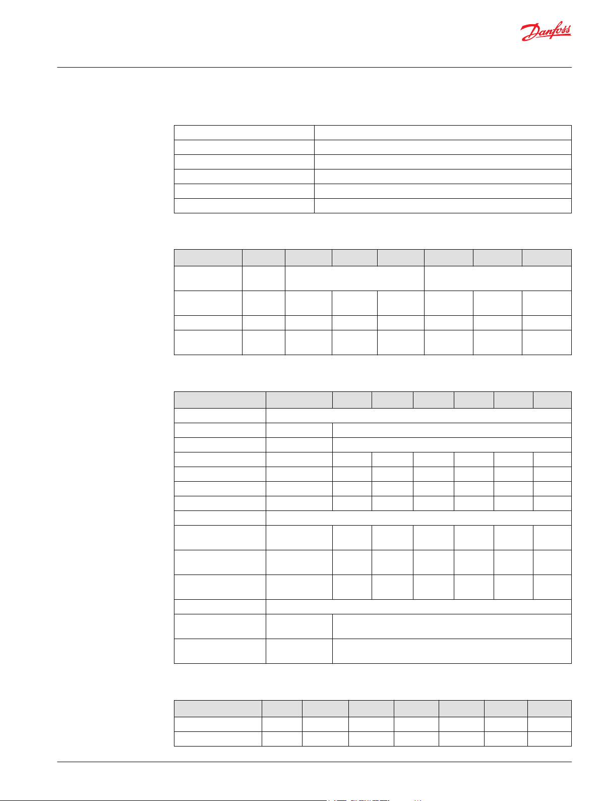
Technical Specifications
Model Unit M25 PV M35 PV M44 PV M25 PT M35 PT M44 PT
Pump
configuration
Displacement cm3/rev
Weight kg [lb] 19 [41.5] 25 [55] 25 [55] 24 [56] 45 [99] 45 [99]
Mass moment of
inertia
[in3/rev]
2
kg·m
[slug·ft2]
Single variable pump Tandem variable pump
24.6 [1.50] 35.0 [2.14] 43.5 [2.65] 24.6 x 2
[1.50 x 2]
0.0018
[0.0014]
0.0033
[0.0024]
0.0032
[0.0023]
0.0037
[0.0028]
35.0 x 2
[2.14 x 2]
0.0066
[0.0048]
43.5 x 2
[2.65 x 2]
0.0064
[0.0047]
Operating Parameters
Model Unit M25 PV M35 PV M44 PV M25 PT M35 PT M44 PT
Case pressure
Continuous bar [psi] 1.7 [25]
Maximum bar [psi] 5.2 [75]
Speed limits
Rated @ max angle min-1 (rpm) 4000 3600 3300 4000 3600 3300
Maximim @ max angle min-1 (rpm) 5000 4500 4100 5000 4500 4100
Minimum min-1 (rpm) 500 500 500 500 500 500
System pressure
Maximum Working bar [psi] 345
[5000]
Maximum bar [psi] 385
[5584]
Theoretical max flow at
rated speed (per pump)
Inlet pressure
Continuous bar absolute
Maximum bar absolute
l/min
[US gal/min]
[in Hg vacuum]
[in Hg vacuum]
100
[26.0]
0.8 [6.3]
0.7 [9.2]
380 [5511] 345
[5000]
415 [6019] 415
[6019]
126
[33.4]
145
[38.3]
345
[5000]
385
[5584]
100
[26.0]
380
[5511]
415
[6019]
126
[33.4]
345
[5000]
415
[6019]
145
[38.3]
Options
Model Unit M25 PV M35 PV M44 PV M25 PT M35 PT M44 PT
Type of mounting SAE B SAE B SAE B SAE B SAE B SAE B
Port connections Twin Twin Twin Twin Twin Twin
©
Danfoss | July 2017 520L0635 | BC00000106en-US0703 | 5
Page 6
Technical Information
Series 40 Direct Displacement Pumps
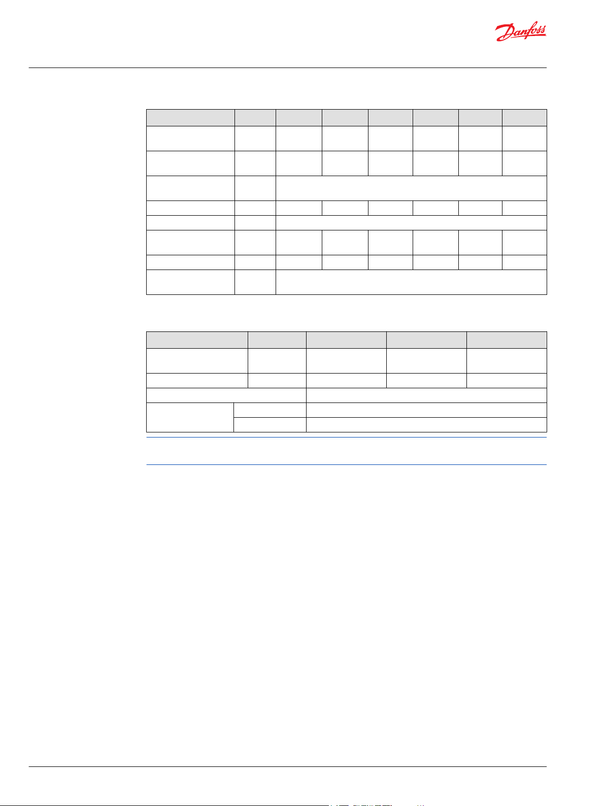
Specifications
Model Unit M25 PV M35 PV M44 PV M25 PT M35 PT M44 PT
Integral charge pump
(std)
Charge relief valve
setting
System pressure
regulation
Displacement limiters - - - - - Input shaft option Splined, Tapered, or Straight Key
Auxiliary mounting
pad
Control options DDC DDC DDC DDC DDC DDC
Filtration
configuration
Fluid Specifications
Parameter Unit Minimum Continuous Maximum
Viscosity mm2/sec (cSt)
Temperature °C [°F] -40 [-40] 82 [180] 104 [220]
Cleanliness ISO 4406 Class 18/13 or better
Filtration efficiency suction filtration β
cm3/rev
[in3/rev]
bar [psi] 14.0
bar [psi] 140-345 [2030-5000]
charge filtration β
- 11.8
[0.72]
14.0
[200]
SAE A SAE A
Suction Filtration or Remote Charge Pressure Filtration
[SUS]
[200]
SAE B
7
[47]
35-44
15-20
=75 (β10≥1.5)
=75 (β10≥10)
11.8
[0.72]
14.0
[200]
SAE A
SAE B
- 16.4
14.0
[200]
SAE A SAE A
12-60
[70-278]
[1.00]
14.0
[200]
SAE B
1600
[7500]
16.4
[1.00]
14.0
[200]
SAE A
SAE B
Ratings and data are based on operation with premium petroleum-based hydraulic fluids containing
oxidation, rust, and foam inhibitors.
6 | © Danfoss | July 2017 520L0635 | BC00000106en-US0703
Page 7
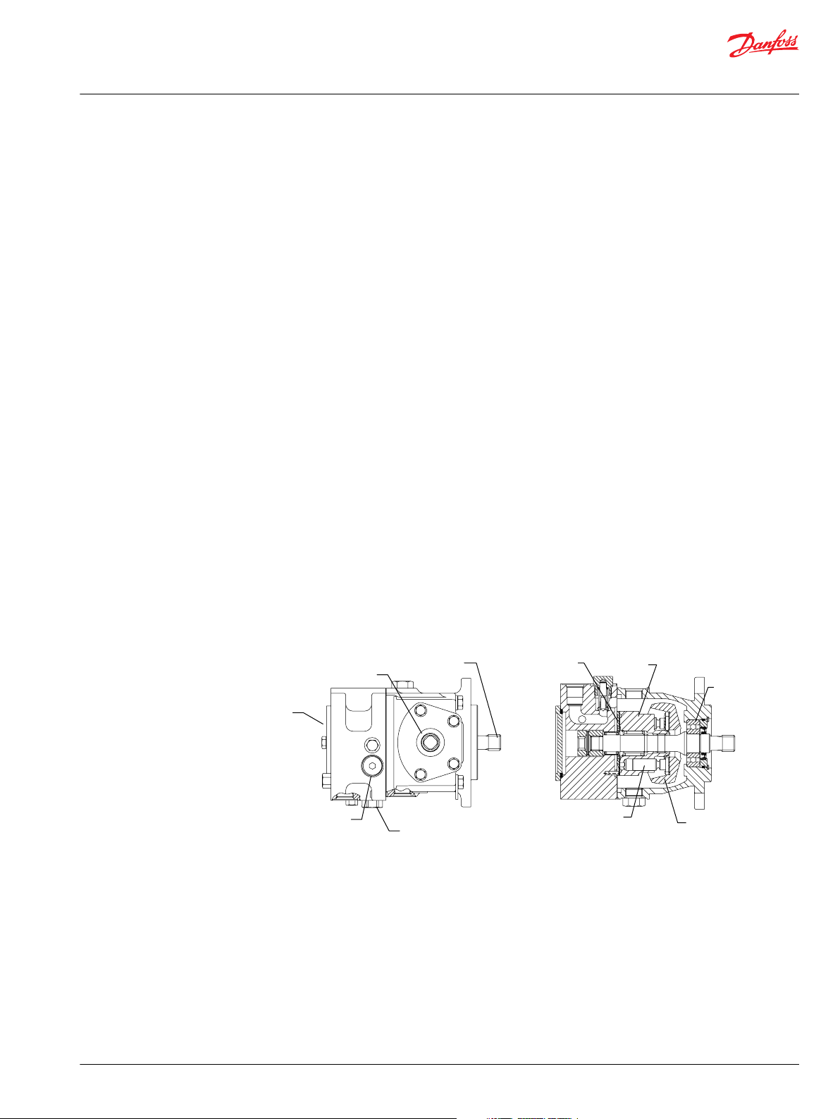
Input
shaft
Auxiliary
pad
Trunnion
Charge check and
high pressure relief
valve with bypass
Charge relief
valve
Swashplate
Piston
Cylinder
block
Ball
bearing
Valve plate
P100 583E
Technical Information
Series 40 Direct Displacement Pumps
General Information
Series 40 Family of Pumps and Motors
Series 40 is a family of hydrostatic pumps and motors for medium power applications with maximum
loads of 345 bar [5000 psi]. These pumps and motors can be applied together or combined with other
products in a system to transfer and control hydraulic power.
Series 40 pump + motor transmissions provide an infinitely variable speed range between zero and
maximum in both forward and reverse modes of operation. The pumps and motors each come in four
frame sizes: M25, M35, M44, and M46.
Series 40 pumps are compact, high power density units. All models use the parallel axial piston / slipper
concept in conjunction with a tiltable swashplate to vary the pump’s displacement. Reversing the angle
of the swashplate reverses the flow of fluid from the pump, reversing the direction of rotation of the
motor output.
Series 40 - M35 and M44 pumps may include an integral charge pump to provide system replenishing
and cooling fluid flow. M25 pumps are designed to receive charge flow from an auxiliary circuit or from a
gear pump mounted on the auxiliary mounting pad. Series 40 pumps feature a range of auxiliary
mounting pads to accept auxiliary hydraulic pumps for use in complementary hydraulic systems.
For complete technical information on M46 pumps, refer to M46 Pumps Technical Information, L1001029.
Series 40 motors use the parallel axial piston/slipper design in conjunction with a fixed or tiltable
swashplate. The family includes M25, M35, M44 fixed motor units and M35, M44, M46 variable motor
units. For complete technical information on Series 40 motors, refer to Series 40 Motors Technical
Information, 520L0636.
The M35 and M44 variable motors feature a trunnion style swashplate and direct displacement control.
The M46 variable motors use a cradle swashplate design and a two-position hydraulic servo control.
The M46 variable motor is available in a cartridge flange version, which is designed to be compatible with
CW and CT compact planetary gearboxes. This combination provides a short final drive length for
applications with space limitations.
M25 Variable Pump
©
Danfoss | July 2017 520L0635 | BC00000106en-US0703 | 7
Page 8
Input
shaft
Auxiliary
pad
Trunnion
Charge check and
high pressure relief
valve with bypass
Charge relief
valve
Charge
pump
Swashplate
Cylinder
block
Ball
bearing
Valve plate
Piston
P100 584E
S
M3
A
B
M2
M1
L1
E
L2
EE
D
No relief valve
Suction Filtration
Remote Pressure Filtration
Remote pressure filtration
(no charge pump)
P100 638E
Technical Information
Series 40 Direct Displacement Pumps
General Information
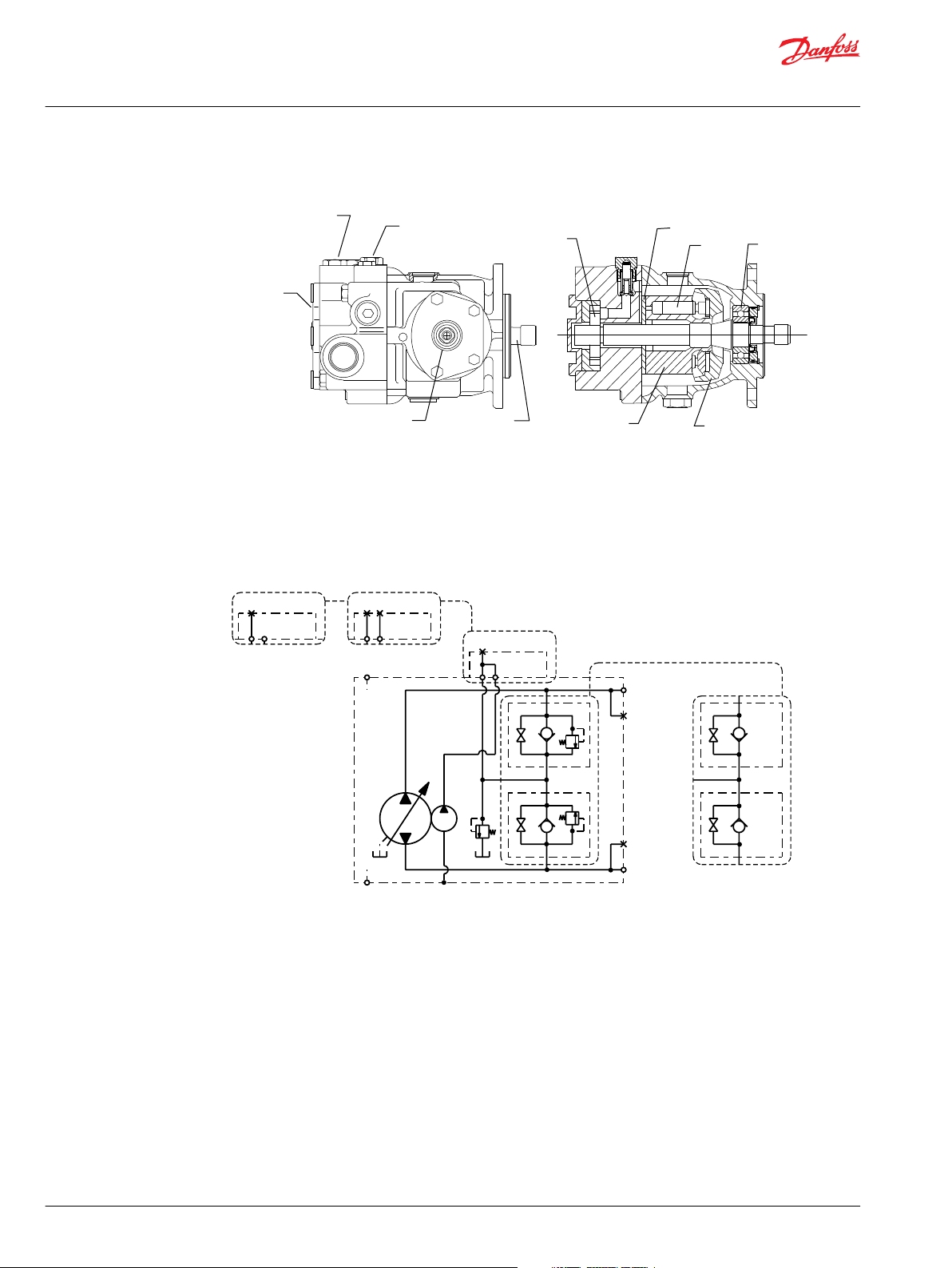
M35 Variable Pump (M44 is similar)
A variable pump is shown in a hydraulic circuit with a fixed motor. The pump shown features manual
displacement control. The circuit features suction filtration and heat exchanger.
M35/44 Pump Schematic
8 | © Danfoss | July 2017 520L0635 | BC00000106en-US0703
Page 9

Technical Information
Series 40 Direct Displacement Pumps
Features and Options
Key Features
3 sizes of variable displacement pumps
•
3 sizes of tandem pumps
•
3 sizes of variable displacement motors
•
3 sizes of fixed displacement motors
•
Efficient axial piston design
•
Proven reliability and performance
•
Compact, lightweight
•
Worldwide sales and service
•
Options
High Pressure Relief Valve (HPRV) - A high pressure relief valve limits the system pressure to protect
the system from over-pressure.
Charge Relief Valve - The charge pressure relief valve regulates charge pressure.
Displacement Limiters - Optional displacement limiters allow maximum displacement adjustment to
allow for fine tuning of the propel system.
Auxiliary Mounting Pads - Several auxiliary mounting pad options allow for adding a second pump.
Input Shafts - Straight keyed, tapered keyed, and several splined shaft options are available.
©
Danfoss | July 2017 520L0635 | BC00000106en-US0703 | 9
Page 10
Technical Information
Series 40 Direct Displacement Pumps
Operating Parameters
Fluids
Ratings and performance data are based on operating with premium hydraulic fluids containing
oxidation, rust, and foam inhibitors. These include premium turbine oils, API CD engine oils per SAE J183,
M2C33F or G automatic transmission fluids (ATF), Dexron II (ATF) meeting Allison C-3 or Caterpillar T0‑2
requirements, and certain specialty agricultural tractor fluids. For more information on hydraulic fluid
selection, see Danfoss publications: Hydraulic Fluids and Lubricants, Technical Information, 520L0463 and,
Experience with Biodegradable Hydraulic Fluids, Technical Information,520L465.
Viscosity
Maintain fluid viscosity within the recommended range for maximum efficiency and bearing life.
Minimum viscosity is acceptable only during brief occasions of maximum ambient temperature and
severe duty cycle. Maximum viscosity is acceptable only at cold start: Limit speeds until the system warms
up. See Danfoss publications: Hydraulic Fluids and Lubricants, Technical Information, 520L0463, and
Experience with Biodegradable Hydraulic Fluids, Technical Information, 520L465.
Fluid viscosity limits
Condition mm2/s (cSt) SUS
Minimum 7 47
Continuous 12-60 70-278
Maximum 1600 7500
Temperature
Charge Pressure
Case Pressure
Maintain fluid temperature within the limits shown in the table. Minimum temperature relates to the
physical properties of the component materials. Cold oil will not affect the durability of the motor
components. However, it may affect the ability of the motor to transmit power. Maximum temperature
is based on material properties: Don’t exceed it. Measure maximum temperature at the hottest point in
the system. This is usually the case drain.
Ensure fluid temperature and viscosity limits are concurrently satisfied.
Temperature limits
Minimum (intermittent, cold start) - 40° C [- 40° F]
Continuous 82.2° C [180° F]
Maximum 104.4° C [220° F]
All systems require a charge (positive pressure) in the low side of the system loop for proper lubrication
and rotating group operation. Maintain low loop (charge) pressure at a minimum of 6 bar [87 psi] above
case pressure.
Maintain case pressure within the limits shown in the table. Ensure housing is filled with hydraulic fluid.
Case pressure limits
Maximum (continuous) 1.7 bar [25 psi]
Intermittent (cold start) 5.2 bar [75 psi]
10 | © Danfoss | July 2017 520L0635 | BC00000106en-US0703
Page 11

C
W
Technical Information
Series 40 Direct Displacement Pumps
Operating Parameters
Caution
Operating outside of charge and case pressure limits will damage the pump. To minimize this risk, use full
size inlet and case drain plumbing, and limit line lengths.
Pressure Ratings
System pressure is the differential pressure between high pressure system ports. It is the dominant
operating variable affecting hydraulic unit life. High system pressure, which results from high load,
reduces expected life. Hydraulic unit life depends on the speed and normal operating, or weighted
average, pressure that can only be determined from a duty cycle analysis.
Application pressure is the high pressure relief or pressure limiter setting normally defined within the
order code of the pump. This is the applied system pressure at which the driveline generates the
maximum calculated pull or torque in the application.
Maximum Working pressure is the highest recommended application pressure. Maximum working
pressure is not intended to be a continuous pressure. Propel systems with application pressures at, or
below, this pressure should yield satisfactory unit life given proper component sizing.
Maximum pressure is the highest allowable application pressure under any circumstance. Application
pressures above maximum working pressure will only be considered with duty cycle analysis and factory
approval.
Minimum low loop pressure must be maintained under all operating conditions to avoid cavitation.
Speed Ratings
Inlet Pressure
All pressure limits are differential pressures referenced to low loop (charge) pressure. Subtract low loop
pressure from gauge readings to compute the differential.
The table, Operating Parameters in the Specifications section, gives rated and maximum speeds for each
displacement. Not all displacements operate under the same speed limits. Definitions of these speed
limits appear below.
Continuous speed is the maximum recommended operating speed at full power condition. Operating at
or below this speed should yield satisfactory product life. Do not exceed maximum motor speed during
unloaded, on-road travel over level ground.
Maximum speed is the highest operating speed permitted. Exceeding maximum speed reduces pump
life and can cause loss of hydrostatic power and braking capacity. Never exceed the maximum speed
limit under any operating conditions.
Warning
Unintended vehicle or machine movement hazard.
The loss of hydrostatic drive line power, in any mode of operation (forward, neutral, or reverse) may cause
the system to lose hydrostatic braking capacity. You must provide a braking system, redundant to the
hydrostatic transmission, sufficient to stop and hold the vehicle or machine in the event of hydrostatic
drive power loss.
Achieving acceptable pump life and performance requires proper charge pump inlet design. A
continuous inlet pressure of not less than 0.8 bar abs. (not more than 6.3 in. Hg vac.) is recommended.
Normal pressure less than the minimum inlet pressure of 0.7 bar abs. (greater than 9.2 in. Hg vac.)
indicates inadequate inlet design or a restricted filter. Pressures less than 0.7 bar abs. (greater than 9.2 in.
Hg vac.) during cold start are possible, but should improve quickly as the fluid warms.
©
Danfoss | July 2017 520L0635 | BC00000106en-US0703 | 11
Page 12

Technical Information
Series 40 Direct Displacement Pumps
Operating Parameters
Inlet pressure
Continuous 0.8 6
Minimum 0.7 9.2 (max)
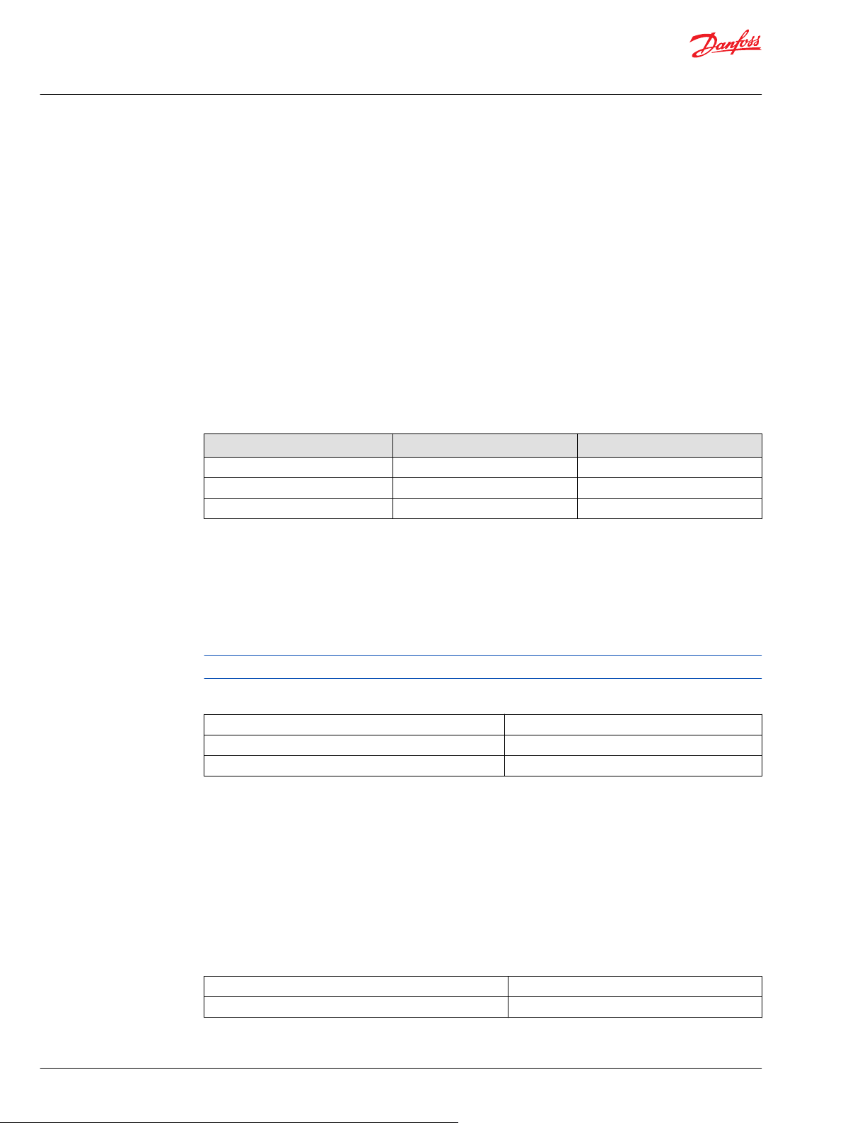
Theoretical Output
The theoretical maximum flow at rated speed is a simple function of pump displacement and speed. This
is a good gauge for sizing a companion motor. This does not take into account losses due to leakage or
variations in displacement.
bar absolute in. Hg vacuum
12 | © Danfoss | July 2017 520L0635 | BC00000106en-US0703
Page 13
Based on SI units
= (l/min)
Input torque M = (N•m)
Input power P = = (kW)
Based on US units
= (US gal/min)
Input torque M = (lbf•in)
Input power P = = (hp)
Vg • n • η
v
1000
Vg • ∆p
20 • π • η
m
Q • ∆p
600 • η
t
M • n • π
30 000
Vg • n • η
v
231
Vg • ∆p
2 • π • η
m
Q • ∆p
1714 • η
t
M • n • π
198 000
Flow
Torque
Power
Technical Information
Series 40 Direct Displacement Pumps
System Design Parameters
Sizing Equations
Use these equations to help choose the right pump size and displacement for your application.
Variables
SI units [US units]
Vg = Displacement per revolution cm3/rev [in3/rev]
pO = Outlet pressure bar [psi]
pi = Inlet pressure bar [psi]
∆p = pO - pi (system pressure) bar [psi]
n = Speed min-1 (rpm)
ηv = Volumetric efficiency
ηm = Mechanical efficiency
ηt = Overall efficiency (ηv • ηm)
Filtration
Ensure fluid entering pump is free of contaminants to prevent damage (including premature wear) to the
system. Series 40 pumps require system filtration capable of maintaining fluid cleanliness at ISO
4406-1999 class 22/18/13 or better.
Consider these factors when selecting a system filter:
Cleanliness specifications
•
Contaminant ingression rates
•
Flow capacity
•
Desired maintenance interval
•
Locate filter either on the inlet (suction filtration) or discharge (charge pressure filtration) side of the
charge pump. Series 40 pumps are available with provisions for either strategy.
Typically, a filter with a beta ratio of β10 = 1.5 to 2.0 is adequate. However, open circuit systems supplied
from a common reservoir may have considerably higher requirements. Because each system is unique,
only a thorough testing and evaluation program can fully validate the filtration system. For more
information, see Danfoss publication Design Guidelines for Hydraulic Fluid Cleanliness, 520L0467.
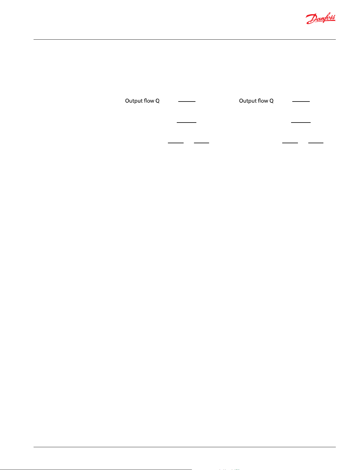
Suction filtration
The suction filter is placed in the circuit between the reservoir and the inlet to the charge pump as shown
in the accompanying illustration.
©
Danfoss | July 2017 520L0635 | BC00000106en-US0703 | 13
Page 14
Reservoir
Filter
Charge
pump
Charge relief
valve
To pump case
To low pressure
side of loop
and servo control
Strainer
P100 588E
Reservoir
Filter
with bypass
Charge
pump
Charge relief
valve
To pump case
To Low Pressure
side of loop
and servo control
Strainer
P106 102E
W
Technical Information
Series 40 Direct Displacement Pumps
System Design Parameters
Suction filtration
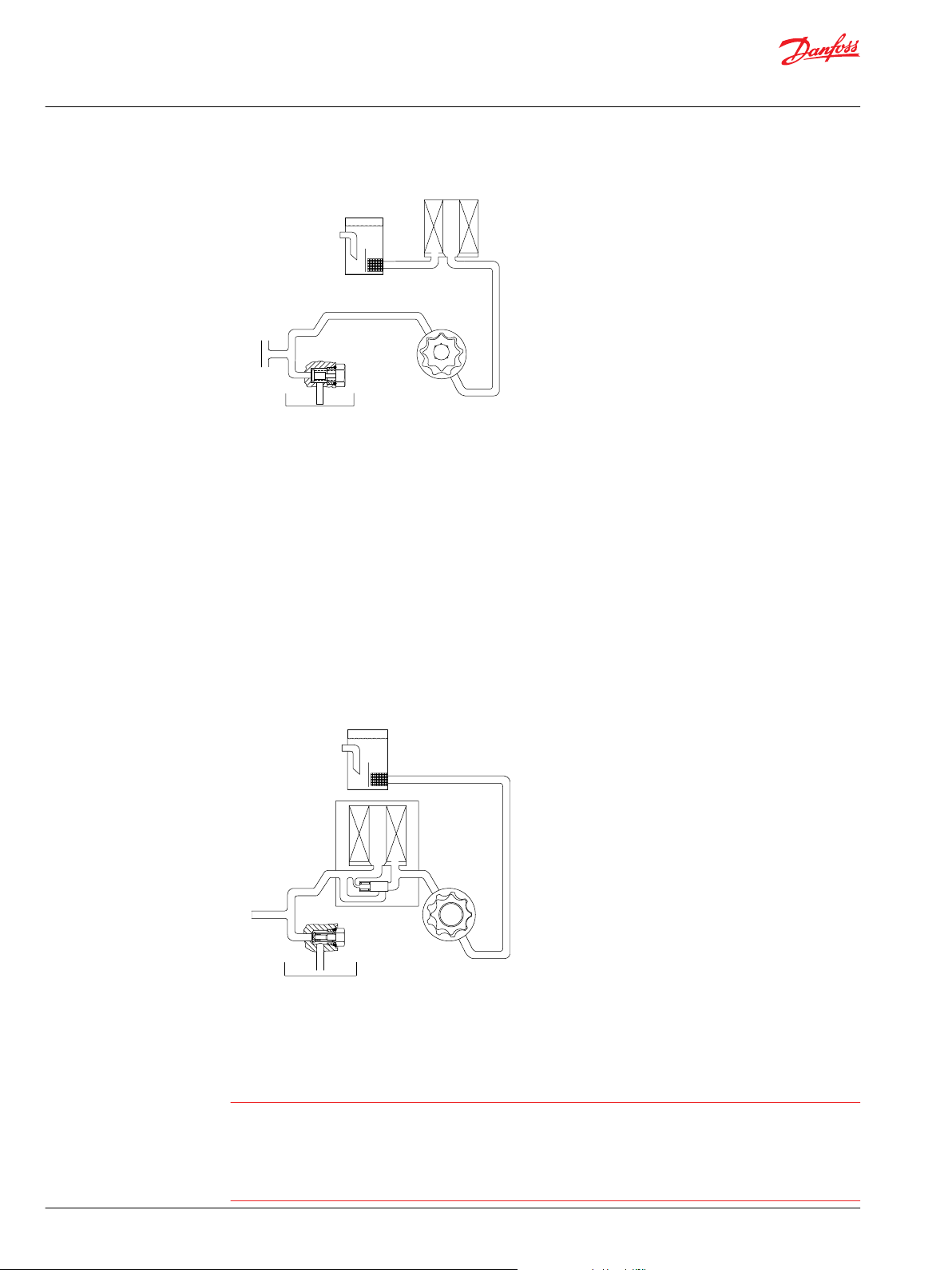
Charge filtration
Provision for charge pressure filtration is available on all Series 40 pumps. The pressure filter is remotely
mounted in the circuit after the charge pump, as shown in the accompanying illustration.
Filters used in charge pressure filtration circuits must be rated to at least 34.5 bar [500 psi] pressure. A 100
- 125 µm screen located in the reservoir or in the charge inlet line is recommended when using charge
pressure filtration.
A filter bypass valve is necessary to prevent filter damage and to avoid contaminants from being forced
through the filter media by high pressure differentials across the filter. In the event of high pressure drop
associated with a blocked filter or cold start-up conditions, fluid will bypass the filter. Avoid working with
an open bypass for an extended period. We recommend a visual or electrical bypass indicator. Proper
filter maintenance is mandatory.
Charge filtration
Redundant Braking System Requirement
Warning
Unintended vehicle or machine movement hazard.
The loss of hydrostatic drive line power, in any mode of operation (forward, neutral, or reverse) may cause
the system to lose hydrostatic braking capacity. You must provide a braking system, redundant to the
14 | © Danfoss | July 2017 520L0635 | BC00000106en-US0703
hydrostatic transmission, sufficient to stop and hold the vehicle or machine in the event of hydrostatic
drive power loss.
Page 15

Technical Information
Series 40 Direct Displacement Pumps
System Design Parameters
Loop Flushing
Closed circuit systems may require loop flushing to meet temperature and cleanliness requirements. A
loop flushing valve removes hot fluid from the low pressure side of the system loop for additional cooling
and filtering. Ensure the charge pump provides adequate flow for loop flushing and the loop flushing
valve does not cause charge pressure to drop below recommended limits.
Reservoir
The reservoir provides clean fluid, dissipates heat, and removes entrained air from the hydraulic fluid. It
allows for fluid volume changes associated with fluid expansion and cylinder differential volumes.
Minimum reservoir capacity depends on the volume needed to perform these functions. Typically, a
capacity of one half the charge pump flow (per minute) is satisfactory for a closed reservoir. Open circuit
systems sharing a common reservoir require greater fluid capacity.
Locate the reservoir outlet (suction line) near the bottom, allowing clearance for settling foreign particles.
Use a 100 - 125 µm screen covering the outlet port.
Place the reservoir inlet (return lines) below the lowest expected fluid level, as far away from the outlet as
possible.
Use a baffle (or baffles) between the reservoir inlet and outlet ports to promote de-aeration and reduce
fluid surging.
Case Drain usage for Tandem Pumps
On tandem pumps, excess flow from the charge relief valve is routed into the housing of the front pump.
In order to ensure adequate case flushing, it is recommended that the rear housing drain ports be used as
the case drain.
M43/M44 tandem pumps with the option of opposing port endcaps do not follow the above rule.
Bearing Life and External Shaft Loading
Bearing life is a function of speed, pressure and swashplate angle plus any external loads. Other life
factors include oil type and viscosity.
In vehicle propulsion drives with no external loads, where the speed, pressure, and swashplate angle are
often changing, normal bearing B10 (90% survival) life will exceed the hydraulic unit life.
In non-propel drives, such as conveyors or fan drives, the operating speed and pressure may be nearly
constant leading to a distinctive duty cycle compared to that of a propulsion drive. In these types of
applications, a bearing life review is recommended.
Series 40 pumps are designed with bearings that can accept some incidental external radial and thrust
loads. However, any amount of external load will reduce the expected bearing life.
The allowable radial shaft loads are a function of the load position, the load orientation, and the
operating pressures of the hydraulic unit. All external shaft loads have an effect on bearing life. In
applications where external shaft loads cannot be avoided, the impact on bearing life can be minimized
by orienting the load to the 90 or 270 degree position.
The maximum allowable radial loads (Re), based on the maximum external moment (Me) and the
distance (L) from the mounting flange to the load, may be determined from the tables below and
drawings on the next page .
The maximum allowable radial load is calculated as: Re = Me / L
Avoid thrust loads in either direction.
If continuously applied external radial loads are 25% or more of the maximum allowable, or thrust loads
are known to occur, contact your Danfoss representative for an evaluation of unit bearing life. Optional
high capacity bearings are available.
©
Danfoss | July 2017 520L0635 | BC00000106en-US0703 | 15
Page 16

L
Re
F
B
Te
P100 594E
CCW
CW
270
Re
0
Re
90
Re
180
Re
F
b
0 Re
180 Re
90 Re 270 Re
Axis of swashplate
rotation
End view
of shaft
P100 595E
Technical Information
Series 40 Direct Displacement Pumps
System Design Parameters
Tapered output shafts or clamp-type couplings are recommended for applications where radial shaft side
loads are present.
Shaft loading parameters
R
e
M
e
L Distance from mounting flange to point of load
F
e
T
e
Maximum external shaft moments
Me/N•m [in·lbf] 101 [890] 121 [1075]
180° External radial shaft load
Maximum radial load
Maximum external moment
Force of cylinder block
Thrust load
M25 M35/44
Direction of external shaft load
Hydraulic Unit Life
Hydraulic unit life is defined as the life expectancy of the hydraulic components. It is a function of speed
and system pressure; however, system pressure is the dominant operating variable. High pressure, which
results from high load, reduces expected life.
Design the hydraulic system to a projected machine duty cycle. Know the expected percentages of time
at various loads and speeds. Ask your Danfoss representative to calculate an appropriate pressure based
your hydraulic system design. If duty cycle data is not available, input power and pump displacement are
used to calculate system pressure.
16 | © Danfoss | July 2017 520L0635 | BC00000106en-US0703
Page 17

Technical Information
Series 40 Direct Displacement Pumps
System Design Parameters
All pressure limits are differential pressures (referenced to charge pressure) and assume normal charge
pressure.
Series 40 pumps will meet satisfactory life expectancy if applied within the parameters specified in this
bulletin. For more detailed information on hydraulic unit life see Pressure and Speed Limits, BLN-9884.
Mounting Flange Loads
Shock load moment is the result of an instantaneous jolt to the system. Continuous load moments are
generated by the typical vibratory movement of the application. Avoid excessive loading of the
mounting flange such as adding tandem mounted auxiliary pumps and/or subjecting pumps to high
shock loads. Design pump applications to stay within the allowable shock load moment and allowable
continuous load moment.
Use the following formulas to estimate overhung load moment for multiple pump mountings:
MS = GS (W1L1 + W2L2 + ... +WnLn)
MC = GC (W1L1 + W2L2 + ... +WnLn)
Refer to the Installation Drawings section to find pump length (L). Refer to the table Technical
Specifications in the Specifications section, to find pump weight (W). An exact measure of W will depend
on the pump’s features.
The tables below show allowable overhung load moment values. If system parameters exceed these
values add additional pump support.
Estimated maximum and continuous acceleration factors for some typical Series 40 applications are
shown. Applications which experience extreme resonant vibrations may require additional pump
support. Typical continuous (vibratory) values can vary significantly due to changes in engine and pump
configuration and mounting methods.
Overhung loading parameters
M
s
M
c
G
s
G
c
W
n
L
n
Shock load moment
Continuous load moment
Maximum shock acceleration (Gs)
Continuous (vibratory) acceleration (Gs)
Weight of nth pump
Distance from mounting flange to center of gravity of nth pump
Allowable overhung parameters
Frame size Continuous load moment (Mc)
N•m [in·lbf]
M25 PV 361 [3200] 617 [5470]
M25 PT 361 [3200] 559 [4950]
M35 PV 517 [4600] 832 [7400]
M35 PT 517 [4600] 754 [6700]
Shock load moment (Ms)
N•m [in·lbf]
©
Danfoss | July 2017 520L0635 | BC00000106en-US0703 | 17
Page 18

Mounting
flange
CG
Pump 1
CG
Pump 2
L1
L2
P100 596E
Technical Information
Series 40 Direct Displacement Pumps
System Design Parameters
Shaft loading parameters
G-factors for sample applications
Application Continuous (vibratory)
Skid steer loader 4 10
Trencher
(rubber tires)
Asphalt paver 2 6
Windrower 2 5
Aerial lift 1.5 4
Turf care vehicle 1.5 4
Vibratory roller 6 10
* Applications which experience extreme resonant vibrations require addition pump support.
acceleration (Gc)
3 8
Maximum (shock) acceleration
(Gs)
18 | © Danfoss | July 2017 520L0635 | BC00000106en-US0703
Page 19

Displacemen t
C D E F G H J
Product Type
K L M N P R S T
M P V 0 2 5 C B A A R A G N N
A A A A A B A A B H A N N N
Displ acemen t
E F G H J
Product Type
Front Pump
C D K L M N P R
Rear Pump
Q D U X V Y Z W
S T
M P T 0 2 5 C S R A E N N
B A A A B D D D L A F F
B C A A B D D D R A F F
C N N N
Technical Information
Series 40 Direct Displacement Pumps
Model Code
Model Code
Model code modules
C: Swashplate group
D: Seal group
F: Rotation
E: Input shaft
G: Charge pump displacement
H: Charge pressure relief setting
J: Filtration
K: Displacement limiters
L: Bypass valve
M: System pressure protection
N: Control
P: Control handle position
R: Control orifice diameters
S: Auxiliary mounting pad
T: Special hardware
Model code modules
©
Danfoss | July 2017 520L0635 | BC00000106en-US0703 | 19
E: Input shaft
F: Rotation
G: Charge pump displacement
H: Charge pressure relief setting
Page 20

Technical Information
Series 40 Direct Displacement Pumps
Model Code
J: Filtration
C & Q: Swashplate
D: Seal group
K & U: Displacement
L & X: Bypass valve
N & Y: Control
M & V: System pressure protection
P & Z: Control handle position
R & W: Control orifice
S: Auxiliary mounting flange
T: Special hardware
20 | © Danfoss | July 2017 520L0635 | BC00000106en-US0703
Page 21

P100 589E
Technical Information
Series 40 Direct Displacement Pumps
Options
Charge Pump
Charge flow is required on all Series 40 units applied in closed circuit installations to make up for internal
leakage, maintain positive pressure in the main circuit, provide flow for cooling, replace any leakage
losses from external valving or auxiliary systems, and on M46 units, to provide flow and pressure for the
control system.
Maintain rated charge pressure under all conditions of operation to prevent damage to the transmission.
Charge pump in series 40 - M35 PV
All Series 40 pumps (except M25 pumps) may be equipped with integral charge pumps. These charge
pump sizes have been selected to meet the needs of a majority of Series 40 applications.
Many factors influence the charge flow requirements and the resulting charge pump size selection. These
factors include system pressure, pump speed, pump swashplate angle, type of fluid, temperature, size of
heat exchanger, length and size of hydraulic lines, control response characteristics, auxiliary flow
requirements, hydraulic motor type, etc. In most Series 40 applications a general guideline is that the
charge pump displacement should be equal to or greater than 10% of the total displacement of all units
in the system.
The total charge flow requirement is the sum of the charge flow requirements of each of the components
in the system. Use the information provided on the following pages to make a charge pump selection for
a given application.
System features and conditions that may invalidate the 10% of displacement rule include (but are not
limited to):
Operation at low input speeds (below 1500 RPM)
•
Shock loading
•
Excessively long system lines
•
Auxiliary flow requirements
•
Use of low speed high torque motors
•
If a charge pump of sufficient displacement to meet the 10% of displacement rule is not available or if any
of the above conditions exist which could invalidate the 10% rule, contact your Danfoss representative. A
charge pump sizing worksheet is available in Selection of Driveline Components, BLN-9885.
M25 pumps do not allow for integral charge pumps. Other Series 40 pumps are also available without
charge pumps. When an integral charge pump is not used, an external charge supply is required to
ensure adequate charge pressure and cooling.
©
Danfoss | July 2017 520L0635 | BC00000106en-US0703 | 21
Page 22

90
0
75
60
45
30
15
24
0
20
16
12
8
4
l/min
US Gal/min
0 1000 2000 3000 4000
Speed min (rpm)
M35 PT
M35 PV
T101 302E
-1
0 1000 2000 3000 4000
0
1
2
3
4
5
6
0
1
2
3
4
hpkW
Speed min (rpm)
M35PT
M35PV
T101 303E
-1
Technical Information
Series 40 Direct Displacement Pumps
Options
Charge Pump Output Flow
Flow at standard charge relief setting, 70°C [160°F] inlet
Charge Pump Power Requirements
Power at standard charge relief setting, 70°C [160°F] inlet
Charge Relief Valve
An integral charge pressure relief valve provides a relief outlet for charge pressure. This valve, in effect,
sets charge pressure. Flow through the valve is ported to case.
The charge relief valve for the M25, M35, and M44 PV/PT is a flat poppet style valve.
The nominal charge relief setting is referenced to case pressure. It is factory set at 1800 min-1 (rpm) with
the pump in neutral position. A proper charge relief setting takes into account input speeds and control
requirements.
The charge pressure setting for pumps without an internal charge pump is set with an externally supplied
charge flow of 19 l/min [5 US gal/min] on pumps and 38 l/min [10 US gal/min] on tandem pumps. These
units must have adequate charge flow supplied to the charge inlet in order to maintain charge pressure
at all times.
22 | © Danfoss | July 2017 520L0635 | BC00000106en-US0703
Incorrect charge pressure settings may result in the inability to build required system pressure and/or
inadequate loop flushing flows. Ensure correct charge pressure under all conditions of operation to
maintain pump control performance.
The charge relief valve is factory set. If necessary, it can be field adjusted with shims.
Page 23

M25 PV
M35 & M44 PV
Charge Relief Valve
P100 591E
C
Technical Information
Series 40 Direct Displacement Pumps
Options
Charge relief valve specs
Type Flat poppet valve
Available setting 6.2-18 bar [90-260 psi] 6.2-24 bar [90-348 psi] 6.2-28.3 bar [90-410 psi]
Adjustment Via shims inside of valve cartridge
*
Shimming offers adustment over a limited range, a spring change may be required to make a larger adjustment.
Charge relief valve locations
M25 M35 M44
*
Charge Check/High Pressure Relief Valve (HPRV)
Charge check and high pressure relief valves maintain circuit pressure in the proper range. The check
valves allow charge flow to replenish the low pressure side of the working loop. The high pressure relief
valves provide pressure protection to the high pressure side of the working loop. There are two cartridge
style valves to handle each side of the working loop with flow in either direction.
High pressure relief valves are available in a range of settings. You may specify individual port pressure
settings . If high pressure relief valves are not desired, pumps may be equipped with charge circuit check
valves only.
Caution
High pressure relief valves are intended for transient overpressure protection and are not intended for
continuous pressure control. Flow over relief valves for extended periods of time may result in severe
heat build up. High flows over relief valves may result in pressure levels exceeding the nominal valve
setting and potential damage to system components.
©
Danfoss | July 2017 520L0635 | BC00000106en-US0703 | 23
Check/high relief valve specs
Type Cartridge-style poppet valve
Setting 140-345 bar (2030-5000 psi)
Option Check only - no relief valve
Page 24

M25 PV
M35 & M44PV
High pressure/check valve
P100 590E
Technical Information
Series 40 Direct Displacement Pumps
Options
High pressure relief valve locations
Auxiliary Mounting Pads and Auxiliary Pumps
Auxiliary mounting pads are available on all Series 40 pumps. A sealed cover is included as standard
equipment on all mounting pads.
An O-ring seals the auxiliary pump mounting flange to the pad. The drive coupling is lubricated with oil
from the main pump case.
Spline specifications and torque ratings are shown in the accompanying table.
All auxiliary mounting pads meet SAE J744 specifications.
•
Do not exceed the maximum pump input shaft rating.
•
Applications subject to severe vibratory or high G loading require an additional structural support.
•
This is necessary to prevent leaks and possible mounting flange damage. Refer to Mounting Flange
Loads in the System Design Parameters section for additional information.
Auxiliary mounting pad specs
Internal
spline
size
9T
16/32P
11T
16/32P
13T
16/32P
Pad
size
SAE A Continuous:
SAE A Continuous:
SAE B Continuous:
Torque rating Availability
N•m [in • lbf] M25 M35 M44
Max:
Max:
Max:
51
107
90
147
124
248
[450]
[950]
[800]
[1300]
[1100]
[2200]
m m m
m m m
— m m
The drawing and table below show the dimensions of the auxiliary pump mounting flanges and shafts.
Auxiliary pump mounting flanges and shafts with the dimensions noted are compatible with the auxiliary
mounting pads on the Series 40 pumps.
24 | © Danfoss | July 2017 520L0635 | BC00000106en-US0703
Page 25

P Dia
E
max
Mounting
flange
(ref
)
D
max
With
undercut
Without
undercut
C
max
B
max
0.8 [0.03] max R
2.3 [0.090]
recommended
cutter clearance
Coupling
F min spline
engagement
for full
torque rating
P100 636E
Technical Information
Series 40 Direct Displacement Pumps
Options
Auxiliary pump mating dimensions mm [in.]
Pad size P B C D E F
SAE A 82.55
[32.50]
SAE B 101.60
[4.000]
6.35
[0.250]
9.65
[0.380]
12.70
[0.500]
15.2
[0.60]
58.2
[2.29]
53.1
[2.09]
15.0
[0.59]
17.5
[0.69]
13.5
[0.53]
14.2
[0.56]
©
Danfoss | July 2017 520L0635 | BC00000106en-US0703 | 25
Page 26

M25 PV
M35 & M44 PV
B Pad
A Pad
P100 593E
M35 & M44 PV
M35 & M44 PV
Technical Information
Series 40 Direct Displacement Pumps
Options
Auxiliary mounting pads on Series 40 pumps
Shaft Options
Series 40 pumps are available with a variety of splined, straight keyed, and tapered shaft ends. Nominal
shaft sizes and torque ratings are shown in the table on the next page.
Torque ratings assume no external radial loading. Continuous torque ratings for splined shafts are based
on splined tooth wear, and assume the mating spline has a minimum hardness of Rc 55 and full spline
depth with good lubrication.
Maximum torque ratings are based on shaft torsional strength and assume a maximum of 200,000 load
reversals.
Recommended mating splines for Series 40 splined output shafts should be in accordance with
ANSIB92.1 Class 5. Danfoss external splines are modified Class 5 Fillet Root Side Fit. The external splined
Major Diameter and Circular Tooth Thickness dimensions are reduced in order to assure a clearance fit
with the mating spline. Other shaft options may exist. Contact your Danfoss representative for
availability.
26 | © Danfoss | July 2017 520L0635 | BC00000106en-US0703
Page 27

6.35 [0.250] Sq. ke
y
38.1 [1.500] long
0.38 [0.015] min. R on edges
Mounting flange
(ref.)
63.5
[2.50]
Coupling must not
protrude beyond
this surface
22.20 dia.
[0.874]
2.84 max.
[0.112]
7.9 [0.31]
P104 403E
7.9 [0.31]
33.32 max
[1.312]
16.5 [0.65] Full spline length
18.8 [0.74] max dia
21.72 [0.855] dia.
20.638 [0.8125] Pitch dia
30° pressure angle
13 teeth, 16/32 pitch
fillet root side fit
per ANSI B92.1 class 5
also mates with
flat root side fit
Coupling must not protrude
beyond this surface
Mounting flange
(ref.)
P104 404E
Technical Information
Series 40 Direct Displacement Pumps
Options
M25 Variable Pump
Code Description Torque rating Drawing
Y Ø 22.20 mm [0.874 in]
Straight keyed
Maximum torque
rating
N•m [lbf•in]
140 [1240] —
Continuous torque
rating
N•m [lbf•in]
A 13-tooth
16/32 pitch
(ANSI B92.1 1970 - Class 5)
140 [1240] 85 [750]
©
Danfoss | July 2017 520L0635 | BC00000106en-US0703 | 27
Page 28

6.35 [0.250] sq. key
38.1 [1.500] long
0.38 [0.015] min. R on edges
Mounting flange
(ref.)
7.9 [0.31]
63.5
[2.50]
Coupling must not
protrude beyond
this surface
22.20 dia.
[0.874]
2.84 max.
[0.112]
P104406
7.9 [0.31]
33.32 max.
[1.312]
16.5 [0.65] full spline length
21.72 [0.588] dia.
18.8 [0.74] max. dia.
20.638 [0.8125] pitch dia.
30° pressure angle
13 teeth, 16/32 pitch
fillet root side fit
per ANSI B92.1 class 5
also mates with
flat root side fit
Coupling must not protrude
beyond this surface
Mounting flange
(ref.)
P104407
22.22 [0.875] Gauge dia.
2.84 [0.112]
max.
24.61 [0.969]
max. Shaft dia.
3/4-16 UNF-2B th
d.
33.3 [1.311]
To gauge dim.
42.8
[1.685]
Mounting
f l
ange
(ref.)
38.1 [1.500] taper per foot
per SAE J501
25.4 [1.000] nominal shaft dia.
except for 24.61 [0.969] dia as shown
coupling must not protrude beyond
25.40 [1.000] max.
26.9
[1.06]
P104 405E
6.35 [0.250] Sq. key
19.05 [0.75] long
0.38 [0.015] min. R on edges
Technical Information
Series 40 Direct Displacement Pumps
Options
M25 Tandem Pump
Code Description Torque rating Drawing
K Ø 22.20 mm [0.874 in]
Straight keyed
Maximum torque
rating
N•m [lbf•in]
140 [1240] —
Continuous torque
rating
N•m [lbf•in]
S 13-tooth
16/32 pitch
(ANSI B92.1 1970 - Class 5)
C Ø 25.4 mm [1.000 in]
1:8 taper (SAE J501)
140 [1240] 85 [750]
140 [1240] —
28 | © Danfoss | July 2017 520L0635 | BC00000106en-US0703
Page 29

63.5
[2.50]
Coupling must not
protrude beyond
this surface
2.85 [0.112] max.
6.35 [0.250] sq. key
38.1 [1.500] long
0.38 [0.015] min. R on edges
22.2 [0.874] dia.
7.9 [0.31]
Mounting flange
(ref.)
P104 409E
Y teeth, 16/32
30° pressure angle
fillet root side fit
per ANSI B92.1-1970
class 5
Also mates with
flat root side fit
7.9 [0.31]
Coupling must not protrude
beyond this surface
Mounting flange
(ref)
P104 410E
T
33.3 [1.31]
U
V
W dia pitch
Shaft
option
Shaft dia. Full spline Major dia. Pitch dia. No. teeth
T U V W Y
G 21.97
[0.865]
18.5 [0.73] 24.89
[0.9800
23.812
[0.9375]
15
A 18.8 [.074] 16.50.65 21.72
[0.855]
20.638
[0.8125]
13
3/4-16 UNF-2B thd.
42.8 [1.685]
1.50 in/ft
per SAE
standard J501
25.4 [1.000] Nom
shaft dia.
26. 9
[1.06]
22.2 [0.875] Gauge dia.
2.84 [0.112] max.
33.3 [1.311] Gauge dim.
Coupling must not
protrude beyond
25.4 [1.000] max.
Mounting flange
(ref.)
P104 411E
6.35 [0.250] Sq. key
19.05 [0.75] long
0.38 [0.015] min. R on edges
Technical Information
Series 40 Direct Displacement Pumps
Options
M35/44 Variable Pump
Code Description Torque rating Drawing
Y Ø 22.20 mm [0.874 in]
Straight keyed
Maximum torque
rating
N•m [lbf•in]
226 [2000] —
Continuous torque
rating
N•m [lbf•in]
A 13-tooth
16/32 pitch
(ANSI B92.1 1970 - Class 5)
G 15-tooth
16/32 pitch
(ANSI B92.1 1970 - Class 5)
N Ø 25.4 mm [1.000 in]
1:8 taper (SAE J501)
226 [2000] 124 [1100]
362 [3200] 153 [1350]
497 [4400] —
©
Danfoss | July 2017 520L0635 | BC00000106en-US0703 | 29
Page 30

Y teeth, 16/32
30° pressure angle
fillet root side fit
per ANSI B92.1-1970
class 5
Also mates with
flat root side fit
7.9 [0.31]
Coupling must not protrude
beyond this surface
Mounting flange
(ref.)
P104 418E
T
33.3 [1.31]
U
V
W dia pitch
Option A
Option G
48.9
[1.925]
1.35
[0.053]
T
V
U
33.02
[1.300]
Shaft
option
Shaft dia. Full spline Major dia. Pitch dia. No. teeth
T U V W Y
G 21.97
[0.865]
39.4 [1.55] 24.89
[0.9800]
23.812
[0.9375]
15
A 21.97
[0.865]
18.5 [0.73] 24.89
[0.9800]
23.812
[0.9375]
15
22.22 [0.875] Gauge dia.
2.84 [0.112]
max.
24.61 [0.969]
max. Shaft dia.
3/4-16 UNF-2B th
d.
33.3 [1.311]
To gauge dim.
42.8
[1.685]
Mounting
f l
ange
(ref.)
38.1 [1.500] taper per foot
per SAE J501
25.4 [1.000] nominal shaft dia.
except for 24.61 [0.969] dia as shown
coupling must not protrude beyond
25.40 [1.000] max.
26.9
[1.06]
P104 405E
6.35 [0.250] Sq. key
19.05 [0.75] long
0.38 [0.015] min. R on edges
Coupling must not
protrude beyond
this surface
0.301 ± 0.017
[7.65] ± 0.43
Mounting
flange REF
1.935 ± 0.025
[49.15] ± 0.5
1.26 ± 0.02
[32.1] ± 0.5
Ø 1.243 ± 0.004
[31.57] ± 0.09
1.667 [29.634] pitch diameter
30° pressure angle
Fillet root side fit
Also mates with flat root side fit
Max
Ø 1.013 [25.7]
Input shaft option “F”
Technical Information
Series 40 Direct Displacement Pumps
Options
M35/44 Tandem Pump
Code Description Torque rating Drawing
A
15-tooth
16/32 pitch
(ANSI B92.1 1970 - Class 5)
G
15-tooth
16/32 pitch
(ANSI B92.1 1970 - Class 5)
Maximum torque
rating
N•m [lbf•in]
362 [3200] 153 [1350]
362 [3200] 153 [1350]
Continuous torque
rating
N•m [lbf•in]
C
Ø 25.4 mm [1.000 in]
497 [4400] —
1:8 taper (SAE J501)
F
14-tooth
499 [4416] 488 [4416]
12/24 pitch
(ANSI B92.1-1996 Class 5)
30 | © Danfoss | July 2017 520L0635 | BC00000106en-US0703
Page 31

Trunnion
106 258
100%
100%
CW
Trunnion rotation
CCW
Trunnion rotation
Pu
mp
displacemen
t
Pu
mp
displacemen
t
T101 306E
Technical Information
Series 40 Direct Displacement Pumps
Options
Direct Displacement Control (DDC)
The Direct Displacement Control (DDC) can be located on either side of a Series 40 - M25, M35, or M44
pump. It provides a simple, positive method of control. Movement of the control shaft causes a
proportional swashplate movement, thus varying the pump’s displacement from full displacement in one
direction to full displacement in the opposite direction.
Some applications (generally vehicle propel) require a provision for non-linear control input to reduce
control sensitivity near neutral. Damping or frictional forces may be necessary to produce desirable
control feel.
Neutral position is not factory set, nor is there any internal neutral return mechanism. The application
must include provisions for all control linkage and neutral return fuctionality.
With no external forces applied to the swashplate trunnion, internal hydraulic forces may not return the
swashplate to the neutral position under all conditions of operation.
The DDC is available on variable pumps and tandem pumps.
External control handle requirements
Maximum allowable trunnion torque is 79.1 N•m [700 in•lbf] for M25, M35, and M44. Minimum torque
necessary to hold the swashplate at a zero angle for neutral is 2.3 N•m [20 in•lbf]. Maximum trunnion
angle is 15° for M25 and 16° for M35 and M44.
DDC on Left Side of M35 Pump
Pump Displacement vs Swashplate Rotation
DDC input specs
©
Danfoss | July 2017 520L0635 | BC00000106en-US0703 | 31
Max torque Nm [in·lbf] 79.1 [700]
Min torque Nm [in·lbf] 2.3 [20]
Max angle M25: 15° M35/44: 16°
Page 32

Technical Information
Series 40 Direct Displacement Pumps
Options
Pump flow direction
Input shaft rotation CW CCW
Trunnion location Right Left Right Left
Trunnion rotation CW CCW CW CCW CW CCW CW CCW
PV or front PV Port A Flow Out In In Out In Out Out In
Rear PT Port C (A) Fow In Out Out In Out In In Out
Fort B Flow In Out Out In Out In In Out
Port D (B) Flow Out In In Out In Out Out In
32 | © Danfoss | July 2017 520L0635 | BC00000106en-US0703
Page 33

0.375-16 UNC-2B thd
19.8 [0.78 min. full t
hd.
(2) places
53.188
[2.094]
106.375 [4.188]
Running cover
SAE A Auxiliary mounting
flange
0.5 max R
[0.02]
88.65 dia
[3.490]
82.6 dia
[3.252]
1.96 [0.077]
6.1 [0.24] min.
M min.
Y min.
Mounting flange
[ref.
]
P Pitch diameter
30 pressure angle
N teeth, 16/32 pitch
fillet root side fit
per ANSI B92.1-1970
Class 7 (see table)
O-ring seal required
ref. 82.22 [3.237] I.D.x
2.62 [0.103] cross section
189.7
[7.47]
53.975 [2.125]
(4) places
63.50 [2.500]
(4) places
0.4375-14 UNC-2B thd.
19 [0.75] min. full thd.
(4) places
Running cover
P100 603E
Technical Information
Series 40 Direct Displacement Pumps
Installation Drawings
M25 Variable Pump
Auxiliary mounting flange
M25PV Auxiliary flange coupling options
Auxiliary mounting
flange
SAE A Option A 14.30
SAE A Option D 17.46
Spline pitch dia.PNumber of teethNShaft clearance
Y
9 34.5
[0.563]
[0.688]
11 39.6
[1.36]
[1.56]
Coupling clearance
M
22.6
[0.89]
25.9
[1.02]
©
Danfoss | July 2017 520L0635 | BC00000106en-US0703 | 33
Page 34

12.7 [0.50]
min.
to shoulder
14.27 [0.562] dia.
(2) places
73.02 [2.875]
(2) places
99.1
[3.90]
112.3
[4.42]
87.4 [3.44]
(2) places
88.4
[3.48]
4.57 R
[0.180]
15.24 dia.
[0.600]
Control
trunnion
left side
option DL
88.4
[3.48]
both
sides
72.1 [2.84]
Case Outlets
(2) places
202.2
[7.96]
54.9
[2.16]
92.7
[3.65]
13.0
[0.51]
77.2
[3.04]
(2) System
ports and
(1) chg. inle
t
101.6 dia
[4.00]
7/8-14*
case outlet L1
9.4
[0.37]
Charge pressure
relief valve
15°
max. displ.
15°
max. displ.
7/16-20*
Change pressure
gauge port M3
Control
trunnion
right side
option DR
133.6
[5.26]
170.7
[6.72]
7/8-14*
Charge pressure inlet E
7/8-14*
Port A
7/8-14*
Port B
7/8-14*
case outlet
(alternate) L2
19.84 dia.
[0.781]
45°
15.82 [0.623]
(2) Places
Control trunion detail
CCW
CW
Bypass/check/relief valve
this side for port A
opposite side for port B
(with 5/16 internal hex)
7/16-20*
gauge port
this side for port A M1
opposite side for port B M2
W
43.2
[1.70]
43.2
[1.70]
0.8 R max.
[0.03]
P100 602E
Technical Information
Series 40 Direct Displacement Pumps
Installation Drawings
Pump and control
*All ports are SAE straight thread o-ring ports per SAE J514, unless otherwise specified.
Shaft rotation is determined by viewing pump from input shaft end.
34 | © Danfoss | July 2017 520L0635 | BC00000106en-US0703
Contact your Danfoss representative for specific installation drawings.
Dimensions in mm [in]
Page 35

Running co ver
4.188
[106.3]
3/8-16 UNC-2B thd.
17.8 [0.70] min. full thd.
(2) places
0.5 max. R
[0.02]
1.0 max. R
[0.04]
88.65 di a.
[3.490]
82.6 di a.
[3.252]
1.96 [0.077]
7.4 [0.29] mi n.
15.2 [0.60] mi n.
Y min.
Mounting flange
[ref.]
P Pitch diameter
30° pressure angl e
N teeth, 16/32 pitch
fillet root side fit
per ANSI B92.1-1970
class 7
(see tab le)
O-ring seal required
Ref. 82.22 [3.237] I. D.x
2.62 [0.103] cross section
SAE A Auxiliary mounting
flange
318.5
[12.54]
Running cover
53.19
[2.094]
P100 612E
Technical Information
Series 40 Direct Displacement Pumps
Installation Drawings
M25 Tandem Pump
Auxiliary mounting flange
©
Danfoss | July 2017 520L0635 | BC00000106en-US0703 | 35
Page 36

12.7 [0.50]
min.
to shoulder
14.27 [0.562] dia.
(2) places
73.02 [2.875]
(2) places
99.1
[3.90]
112.3
[4.42]
87.4 [3.44]
(2) places
88.4
[3.48]
4.57 R
[0.180]
15.24 dia.
[0.600]
Control
trunnions
left side
option DL
88.4
[3.48]
both
sides
72.1 [2.84]
(2) case outlets
211.6
[8.33]
54.9
[2.16]
249.4
[9.82]
152.4 [6.00]
to C.G.
332.5
[13.09]
13.0
[0.51]
Approx.center
of gravity
77.2
[3.04]
(4) system
ports and
(1) charge
inlet
15°
max. displ.
15°
max. displ.
101.6 dia.
[4.00]
7/8-14*
case outlet L1
9.4 [0.37]
Bypass/check/relief valve
this side for port C
opposite side for port D
(5/16 internal hex)
Charge
pressure
relief val
ve
15°
max. displ.
15°
max. displ.
Bypass/check/relief valve
this side for port A
opposite side for port B
(5/16 internal hex)
Control
trunnions
right side
option DR
133.6
[5.26]
170.7
[6.72]
7/8-14*
Port D
7/8-14*
Charge pressure inlet E
7/8-14*
Port A
7/8-14*
Port C
43.2
[1.70]
7/8-14*
Port B
7/8-14*
Case outlet
(alternate) L2
CCW
CW
19.84 dia.
[0.78]
45°
15.82 [0.623]
(2) places
Control trunion detail
43.2
[1.70]
0.8 R max.
[0.03]
P100 611E
Technical Information
Series 40 Direct Displacement Pumps
Installation Drawings
Pump and control
*All ports are SAE straight thread o-ring ports per SAE J514, unless otherwise specified.
Shaft rotation is determined by viewing pump from input shaft end.
Contact your Danfoss representative for specific installation drawings.
Dimensions in mm [in]
36 | © Danfoss | July 2017 520L0635 | BC00000106en-US0703
Page 37

0.375-16 Thd. thru
(4) holes
0.500-13 Thd. thru
(2) holes
SAE B Auxiliary mounting flange
Option B
73.03
[2.875]
146.05
[5.75]
10.7 min. [0.42]
1.96 [0.077]
P pitch dia.
30° pressure angle
N teeth, 16/32 pitch
fillet root side fit
per ANSI B92.1-1970
class 5
(see table)
261.2 [10.66]
Y min.
101.65 dia.
[4.002]
0.76 max. R
[0.30]
0.5 max. R
[0.02]
O-Ring seal required
2.62 [0.103] dia.
cross section
M min.
107.82
[4.245]
Mounting flange
(ref.)
System ports
(ref.)
SAE A Auxiliary mounting flange
Options A and D
106.38
[4.188]
53.19
[2.094]
106.38
[4.188]
P pitch dia.
30° pressure angle
N teeth, 16/32 pitch
fillet root side fit
per ANSI B92.1-1970
class 5
(see table)
7.4 min.
[0.29]
1.0 max. R
[0.04]
0.5 max. R
[0.02]
82.6 dia.
[3.252]
88.65 dia.
[3.490]
O-Ring seal required
ref. 82.22 [3.237] ID x
2.62 [0.103] dia. cross section
Y min.
M min.
Option A: 248.7 [10.15]
Option D:264.0 [10.39]
Mounting flange
(ref.)
System ports
(ref.)
53.19
[2.094]
1.96
[0.077]
90.2
[3.55]
80.4
[3.17]
(2) places
RUNNING COVER
P100 615E
Technical Information
Series 40 Direct Displacement Pumps
Installation Drawings
M35/44 Variable Pump
Auxiliary mounting flange
M35/44 PV Auxiliary mounting flange and coupling option
Auxiliary mounting flange Spline pitch dia.
©
Danfoss | July 2017 520L0635 | BC00000106en-US0703 | 37
SAE A Option A 14.30 [0.563] 9 33.0 [1.30] 9.1 [0.36]
SAE A Option D 17.46 [0.688] 11 39.1 [1.54] 9.1 [0.36]
SAE B Option B 20.72 [0.813] 13 42.9 [1.69] 22.3 [0.91]
P
No. teethNShaft clearanceYCoupling clearance
M
Page 38

1-5/16 - 12*
charge pump inlet S
76.2
[3.00]
(2) places
case outlets
25.4
[1.00]
Approx.center of gravity
Bypass/check/relief valve
this side for port A
opposite side for port B
(5/16 internal hex)
193.3
[7.61]
121.4
[4.78]
12.7
[0.50]
16° max. displ.
16° max. displ.
Control trunnion
left side
option DL
Control trunnion
right side
option DR
87.4
[3.44]
(2) Places
73.03
[2.875]
(2) Places
4.57 R
[0.180]
(4) places
15.24 dia.
[0.600]
(2)places
111.8
[4.40]
14.27 dia.
[0.562]
(2) Places
95
[3.74]
3.3
[0.13]
125
[4.92]
35
[1.38]
1-1/16 - 12*
Case outlet L2
(Alternate)
164.6
[6.48]
1-1/16 - 12*
Port B
74.9 min. dia.
[2.95]
Charge pressure
relief valve
1-1/16 - 12*
case outlet L1
239.3
[9.42]
101.6 dia.
[4.000]
9.4
[0.37]
66.7
[2.625]
96.5
[3.80]
(2) places
7/8 - 14*
charge pressure
gauge port M3
(suction filter option)
9/16 - 18*
system pressure
gauge port M1
(for port A)
9/16 - 18*
system pressure
gauge port M2
(for port B)
7/8 - 14*
from remote filter E
(pressure filter option)
or charge pressure inlet E
(no charge pump option)
35.6
[1.40]
Top view
Suction filtration
Top view
Remote filtration or less charge pump
35
[1.38]
7/8 - 14*
to remote filter D
(pressure filter option)
1-1/16 - 12*
Port A
Pump
79.8
[3.14]
(2) places
Section B-B
183.4
[7.22]
203.4
[8.01]
Mounting flange
(ref.)
M35: 19.8 dia.
[0.781]
M44:23.8 dia.
[0.938]
45
M35:
15.8 [0.623]
(2) places
M44:
19.0 [0.748]
(2) places
M35 Control trunion detail
96.5
[3.80]
Control side
92.5
[3.64]
B
B
CCW C W
0.8 R max.
[0.03]
P104 614E
Technical Information
Series 40 Direct Displacement Pumps
Installation Drawings
Pump, filtration/charge pump option, control
*All ports are SAE straight thread o-ring ports per SAE J514, unless otherwise specified.
Shaft rotation is determined by viewing pump from input shaft end.
Contact your Danfoss representative for specific installation drawings.
38 | © Danfoss | July 2017 520L0635 | BC00000106en-US0703
Dimensions in mm [in]
Page 39

SAE B Auxiliary mounting flange
Option B
SAE A Auxiliary mounting flange
Options A and D
w/ charge pump
467.9 [18.42]
w/o charge pump
433.1 [17.05]
73.03
[2.875]
System ports
(ref.)
146.05
[5.75]
0.500-13 Thd.
20.8 [0.82] min. full thd.
(2) places
Mounting flange
(ref.)
23.1 min.
[0.91]
101.65 dia.
[4.002]
107.82 dia.
[4.245]
0.76 max. R
[0.03]
0.5 max. R
[0.02]
1.96
[0.077]
10.7 min.
[0.42]
P pitch di
a.
O teeth, 16/32 pitch
fillet root side fit
per ANSI B92.1-1970
class 5
Charge pressure
relief valve
216.9
[8.54]
7/8 - 14*
charge pressure inlet E
(w/o charge pump)
Top view (without
charge pump)
Pump
84.8
[3.34]
VIEW C-C
1.0 max. R
[0.04]
9.1 [0.36] min.
P pitch di a.
30° pressure angle
N teeth, 16/32 pitch
fillet root side fit
per ANSI B92.1-1970
class 5
(see table)
0.5 max. R
[0.02]
7.4 min.
[0.29]
1.96
[0.077]
O-Ring seal required
ref. 82.22 [3.237] ID x
2.62 [0.103] dia. cross sec tion
82.6 dia.
[3.252]
88.65 dia.
[3.490]
Mounting flange
(ref.)
w/ charge pump
option A: 455.2 [17.92]
option D: 461.3 [18.16]
w/o charge pump
option A: 433.1 [16.55]
option D: 426.5 [16.79]
Y min.
C
C
System ports
(ref.)
53.19
[2.094]
106.38
[4.188]
0.375-16 Thd.
17.8 [0.70] min . th d .
(4) places
53.19
[2.094]
106.38
[4.188]
O-Ring seal required
ref. 101.27 [3.987] ID x
2.62 [0.103] dia. cross
section
Y min.
P100 617E
Technical Information
Series 40 Direct Displacement Pumps
Installation Drawings
M35/44 Tandem Pump
Charge pump options, auxiliary mounting flanges
M35/44 PT Auxiliary mounting flange and coupling options
Auxiliary mounting
flange
SAE A Option A 14.30
Spline pitch dia.
P
[.563]
SAE A Option D 17.46
SAE B Option B 20.72
[.688]
[0.813]
No. teeth
Shaft clearanceYCoupling clearance
N
9 33.0
[1.30]
11 39.1
[1.54]
13 42.9
[1.69]
M
9.1
[0.36]
9.1
[.36]
22.3
[0.91]
©
Danfoss | July 2017 520L0635 | BC00000106en-US0703 | 39
Page 40

15.24 dia.
[0.600]
(4) places
95
[3.74]
1-1/16 - 12*
Port A
205.7 [8.10]
w/ chg. pump
193.3
[7.61]
35
[1.38]
1-1/16 - 12*
Port C
16° max.
displ.
80.3 [3.16]
(4) places
Bypass/check/relief valve
this side for port C and A
opp.side for Port D and B
(5/16 internal hex)
9/16 - 18*
system pressure
guage port M3
(for port C)
25.4
[1.00]
Approx Center Of Gravity
164.6
[6.48]
247.1 [9.73]
w/ chg. pump
428.8 [16.88]
w/ chg. pump
88.9
[3.50]
66.7
[2.625]
345.3 [13.59]
w/chg. pump
1-1/16 - 12*
case outlet L1
76.2
[3.00]
(2) places
case outlets
1-5/16 - 12*
charge pump inlet S
12.7 [0.50]
16° max.
displ.
16° Max.
displ.
16° Max.
displ.
1-1/16 - 12*
Port B
1-1/16 - 12*
Port D
Top view
(with charge pump and
suction filtration)
7/8 - 14*
Charge pressure
gauge port E
9/16 - 18*
system pressure
gauge port M4
(for port D)
charge pressure
relief valve
1-1/16 - 12*
case outlet
(alternate) L2
9/16 - 18*
system pressure
gauge port M1
(for port A)
system pressure
gauge port M2
(for port B)
(on right side)
Pump
79.8
[3.14]
(2) places
VIEW "B-B"
183.4
[7.22]
203.4
[8.01]
7/8 - 14*
from remote filter E
35.6
[1.40]
7/8 - 14*
to remote filter D
Mounting flange
(ref.)
35
[1.38]
393.7 [15.50]
w/o chg. pump
212.3 [8.36]
w/o chg. pump
310.3 [12.215]
w/o chg. pump
Left side view
(with charge pump and suction filtration)
Bottom view
(with charge pump and suction filtration)
315.5 [12.42]
w/ chg. pump
280.7 [11.05]
w/o chg. pump
45°
M35 Control trunion detail
87.4 [3.44]
(2) places
4.57 R
[0.180]
(8) places
73.03 [2.875]
(2) places
14.27 [0.562]
(2) places
Control trunnion
left side
option DL
Control trunnion
right side
option DR
111.8
[4.40]
125
[4.92]
96.5
[3.80]
Control side
92.5
[3.64]
101.6 dia.
[4.00]
9.4
[0.37]
74.9 min. dia.
[2.95]
B
B
CCW
CW
"X"
188.7 [7.43]
w/o chg. pump
0.8 R max.
[0.03]
M35: 19.8 dia.
[0.78]
M44: 23.8 dia.
[0.938]
M35:
15.8 [0.623]
(2) places
M44:
19.0 [0.748]
(2) places
P100 616E
Top view
(with charge pump and
remote pressure filtration)
Technical Information
Series 40 Direct Displacement Pumps
Installation Drawings
Pumps, filtration/charge pump options, control
40 | © Danfoss | July 2017 520L0635 | BC00000106en-US0703
*All ports are SAE straight thread o-ring ports per SAE J514, unless otherwise specified.
Shaft rotation is determined by viewing pump from input shaft end.
Contact your Danfoss representative for specific installation drawings.
Dimensions in mm [in]
Page 41

100
80
95
90
85
Efficienc
y -
%
0 25 50 75 100
Speed - % of rated speed
V
o
l
u
m
e
t
r
i
c
e
f
i
f
i
c
e
n
c
y
-
1
7
0
b
a
r [
25
0
0 p
s
i]
V
o
l
u
m
e
t
r
i
c
e
f
f
i
c
i
e
n
c
y
-
34
5
b
ar
[5
0
00
p
si
]
O
v
e
r
0
p
s
i
]
a
l
l
e
f
f
i
c
i
e
n
c
y
-
1
7
0
b
a
r
[
2
5
0
O
v
e
r
a
l
l
e
f
f
i
c
i
e
n
c
y
-
3
4
5
ba
r
[
5
0
0
0
p
s
i
]
T101 304E
5000
0
4000
3000
2000
1000
System pressur
e
0 25 50 75 100
Speed - % of rated speed
8
0
%
8
0
%
8
5
%
psi
345
0
270
210
140
bar
70
8
5
%
8
7
%
8
7
%
8
8
%
8
8
%
T101 305E
Technical Information
Series 40 Direct Displacement Pumps
Performance Data
Performance
The following performance graph provides typical volumetric and overall efficiencies for Series 40
pumps. These efficiencies apply for all Series 40 pumps.
Pump performance as a function of operating speed
The performance map provides typical pump overall efficiencies at various operating parameters. These
efficiencies also apply for all Series 40 pumps.
Pump performance as a function of operating speed and system pressure
©
Danfoss | July 2017 520L0635 | BC00000106en-US0703 | 41
Page 42

M2
B
M1
A
L1
L2
EM3
No relief valve
P100 637E
S
M3
A
B
M2
M1
L1
E
L2
EE
D
No relief valve
Suction Filtration
Remote Pressure Filtration
Remote pressure filtration
(no charge pump)
P100 638E
Technical Information
Series 40 Direct Displacement Pumps
Schematics
Single Pump Schematics
M25 PV
M35/44 PV
42 | © Danfoss | July 2017 520L0635 | BC00000106en-US0703
Page 43

B
A
L1
D
L2
E
C
No Relief Valve
P100 640E
S
B
M2
M1
A
L1
E
L2
M4
D
M3
C
Suction filtration
Remote pressure
filtration
Remote pressure
filtration
(no charge pump)
E
D
E
No Relief Valve
P100 641E
Technical Information
Series 40 Direct Displacement Pumps
Schematics
Tandem Pump Schematics
M25 PT
M35/44 PT
©
Danfoss | July 2017 520L0635 | BC00000106en-US0703 | 43
Page 44

Danfoss
Power Solutions GmbH & Co. OHG
Krokamp 35
D-24539 Neumünster, Germany
Phone: +49 4321 871 0
Danfoss
Power Solutions ApS
Nordborgvej 81
DK-6430 Nordborg, Denmark
Phone: +45 7488 2222
Danfoss
Power Solutions (US) Company
2800 East 13th Street
Ames, IA 50010, USA
Phone: +1 515 239 6000
Danfoss
Power Solutions Trading
(Shanghai) Co., Ltd.
Building #22, No. 1000 Jin Hai Rd
Jin Qiao, Pudong New District
Shanghai, China 201206
Phone: +86 21 3418 5200
Products we offer:
Comatrol
www.comatrol.com
Turolla
www.turollaocg.com
Hydro-Gear
www.hydro-gear.com
Daikin-Sauer-Danfoss
www.daikin-sauer-danfoss.com
Bent Axis Motors
•
Closed Circuit Axial Piston
•
Pumps and Motors
Displays
•
Electrohydraulic Power
•
Steering
Electrohydraulics
•
Hydraulic Power Steering
•
Integrated Systems
•
Joysticks and Control
•
Handles
Microcontrollers and
•
Software
Open Circuit Axial Piston
•
Pumps
Orbital Motors
•
PLUS+1® GUIDE
•
Proportional Valves
•
Sensors
•
Steering
•
Transit Mixer Drives
•
Danfoss Power Solutions is a global manufacturer and supplier of high-quality hydraulic and
electronic components. We specialize in providing state-of-the-art technology and solutions
that excel in the harsh operating conditions of the mobile off-highway market. Building on
our extensive applications expertise, we work closely with our customers to ensure
exceptional performance for a broad range of off-highway vehicles.
We help OEMs around the world speed up system development, reduce costs and bring
vehicles to market faster.
Danfoss – Your Strongest Partner in Mobile Hydraulics.
Go to www.powersolutions.danfoss.com for further product information.
Wherever off-highway vehicles are at work, so is Danfoss. We offer expert worldwide support
for our customers, ensuring the best possible solutions for outstanding performance. And
with an extensive network of Global Service Partners, we also provide comprehensive global
service for all of our components.
Please contact the Danfoss Power Solution representative nearest you.
Local address:
Danfoss can accept no responsibility for possible errors in catalogues, brochures and other printed material. Danfoss reserves the right to alter its products without notice. This also applies to products
already on order provided that such alterations can be made without changes being necessary in specifications already agreed.
All trademarks in this material are property of the respective companies. Danfoss and the Danfoss logotype are trademarks of Danfoss A/S. All rights reserved.
©
Danfoss | July 2017 520L0635 | BC00000106en-US0703
 Loading...