


Technical Information
Series 40 Axial Piston Motors
powersolutions.danfoss.com

Technical Information
Series 40 Axial Piston Motors
Revision history Table of revisions
Date Changed Rev
February 2017 Corrected document formatting 0703
October 2016 Minor updates 0702
January 2014 Danfoss layout GA
September 2013 add system pressure information FG
June 2013 add anti-cavitation option FF
April 2011 correct system pressure gauge port 7/16-20 FE
August 2010 new back page FD
March 2010 minor edits FC
November 2007 correction to maximum torque rating 15 and 19 tooth FB
April 2007 Revised dimensions for straight keyed shaft FA
September-2006 Corrections in model code examples F
September-2005 Major Revision E
2 | © Danfoss | February 2017 520L0636 | 0703

Technical Information
Series 40 Axial Piston Motors
Contents
General description
Basic design........................................................................................................................................................................................5
Key features........................................................................................................................................................................................ 5
Cross sections.................................................................................................................................................................................... 6
System circuit diagram...................................................................................................................................................................7
M46 motor schematic ....................................................................................................................................................................7
Technical Specifications
Overview..............................................................................................................................................................................................8
General.................................................................................................................................................................................................8
Features and options...................................................................................................................................................................... 8
Specifications.....................................................................................................................................................................................8
Operating parameters.................................................................................................................................................................... 8
Fluid specifications.......................................................................................................................................................................... 9
Hydraulic unit life............................................................................................................................................................................. 9
Performance.......................................................................................................................................................................................9
Bearing life and external shaft loading ................................................................................................................................. 10
Operating Parameters
Fluids.................................................................................................................................................................................................. 12
Viscosity.............................................................................................................................................................................................12
Temperature.................................................................................................................................................................................... 12
Case pressure...................................................................................................................................................................................12
System Pressure..............................................................................................................................................................................13
Speed ratings...................................................................................................................................................................................13
System design parameters
Sizing equations.............................................................................................................................................................................14
Filtration............................................................................................................................................................................................ 14
Bypass valve.....................................................................................................................................................................................14
Loop flushing valve.......................................................................................................................................................................15
Charge Flow.....................................................................................................................................................................................16
Charge Pressure/Open Circuit Operation............................................................................................................................. 16
Redundant braking system requirement..............................................................................................................................16
Reservoir............................................................................................................................................................................................16
Overpressure protection............................................................................................................................................................. 17
Product coding
Revised model code......................................................................................................................................................................18
Model code modules....................................................................................................................................................................18
Fixed motor.................................................................................................................................................................................18
Variable motor...........................................................................................................................................................................18
Features and options
Anti-Cavitation Valve Option.....................................................................................................................................................20
Displacement limiters...................................................................................................................................................................20
Speed sensor option.....................................................................................................................................................................21
Pulse pickup and connector.......................................................................................................................................................23
Shaft options....................................................................................................................................................................................23
Through-shaft options................................................................................................................................................................. 24
Shaft options
M25 MF.............................................................................................................................................................................................. 25
M35/44 MF........................................................................................................................................................................................25
M35/44 MV....................................................................................................................................................................................... 26
M46 MV..............................................................................................................................................................................................27
Control options
Direct displacement control (DDC)......................................................................................................................................... 28
External Control Handle Requirements............................................................................................................................28
Two-position hydraulic control.................................................................................................................................................29
Installation drawings
©
Danfoss | February 2017 520L0636 | 0703 | 3

Technical Information
Series 40 Axial Piston Motors
Contents
M25 MF: axial ports, twin ports, loop flushing, speed sensor........................................................................................30
M25 MF: mounting flange.......................................................................................................................................................... 32
M35/M44 MF: mounting flange................................................................................................................................................32
M35/M44 MF: axial ports, twin ports, loop flushing, speed sensor..............................................................................33
M35/M44 MF: radial ports, twin ports, anti-cavitation valve..........................................................................................34
M35/M44 MF: side ports, through shaft.................................................................................................................................35
M35/M44 MV: twin ports.............................................................................................................................................................36
M35/M44 MV: mounting flange, trunnion control............................................................................................................ 37
M46 MV: side ports, loop flushing............................................................................................................................................37
M46 MV: axial ports, loop flushing...........................................................................................................................................39
M46 MV: side ports, thru shaft twin ports, loop flushing.................................................................................................40
M46 MV: mounting flange..........................................................................................................................................................41
M46 MV: control ports..................................................................................................................................................................42
Schematics
Motor Schematics.......................................................................................................................................................................... 43
4 | © Danfoss | February 2017 520L0636 | 0703

Technical Information
Series 40 Axial Piston Motors
General description
Basic design
Series 40 is a family of hydrostatic pumps and motors for medium power applications with maximum
loads of 345 bar [5000 psi]. These pumps and motors can be applied together or combined with other
products in a system to transfer and control hydraulic power.
Series 40 transmissions (pump plus motor) provide an infinitely variable speed range between zero and
maximum in both forward and reverse modes of operation. The pumps and motors each come in four
frame sizes: M25, M35, M44, and M46.
Series 40 pumps are compact, high power density units. All models use the parallel axial piston / slipper
concept in conjunction with a tiltable swashplate to vary the pump’s displacement. Reversing the angle
of the swashplate reverses the flow of fluid from the pump, reversing the direction of rotation of the
motor output.
Series 40 M35, M44, and M46 pumps may include an integral charge pump to provide system
replenishing and cooling fluid flow, as well as servo control fluid flow on M46 pumps. M25 pumps are
designed to receive charge flow from an auxiliary circuit or from a gear pump mounted on the auxiliary
mounting pad. Series 40 pumps feature a range of auxiliary mounting pads to accept auxiliary hydraulic
pumps for use in complementary hydraulic systems.
Series 40 M46 pumps offer proportional controls with either manual, hydraulic, or electronic actuation.
An electric three-position control is also available. The M25, M35, and M44 pumps include a trunnion
style direct displacement control.
Series 40 motors also use the parallel axial piston / slipper design in conjunction with a fixed or tiltable
swashplate. The family includes M25, M35, M44 fixed motor units and M35, M44, M46 variable motor
units.
The M35 and M44 variable motors feature a trunnion style swashplate and direct displacement control.
The M46 variable motors use a cradle swashplate design and a two-position hydraulic servo control.
Key features
3 sizes of variable displacement motors
•
3 sizes of fixed displacement motors
•
Efficient axial piston design
•
Complete family of control systems
•
Proven reliability and performance
•
Compact, lightweight
•
Worldwide sales and service
•
©
Danfoss | February 2017 520L0636 | 0703 | 5

Swash plate
Piston
Bearing
Cylinder
Displacement limiter
Cylinder block
Piston
Output shaft
Lip seal
Bearing
Cylinder block
Piston
Output shaft
Lip seal
Bearing
Cylinder block
Piston
Output shaft
Lip seal
Bearing
Servo piston
P101738E
Output shaft
Lip seal
Swash plate
Technical Information
Series 40 Axial Piston Motors
General description
Cross sections
M35/M44 variable motor (MV), M25 fixed motor (MF), M35/M44 fixed motor (MF), M46 variable motor (MV) (SAE flange)
6 | © Danfoss | February 2017 520L0636 | 0703
Input
shaft
Suction flow
Servo pressure
High pressure
Case flow
Charge pressure
Output
shaft
Cylinder
block
assembly
Filter
Charge
pump
Reservoir
Fixed displacement
motor
Cylinder
block
assembly
Heat
exchanger
Check valves
w/ high pressure
relief valve
Variable
displacement
pump
Heat exchanger
bypass
Charge relief
valve
Displacement
control
valve
Control
handle
Bypass
valve
Loop flushing
module
P100586E
M2
B
A
M1
X2
X1
L2
L2
P101869
Technical Information
Series 40 Axial Piston Motors
General description
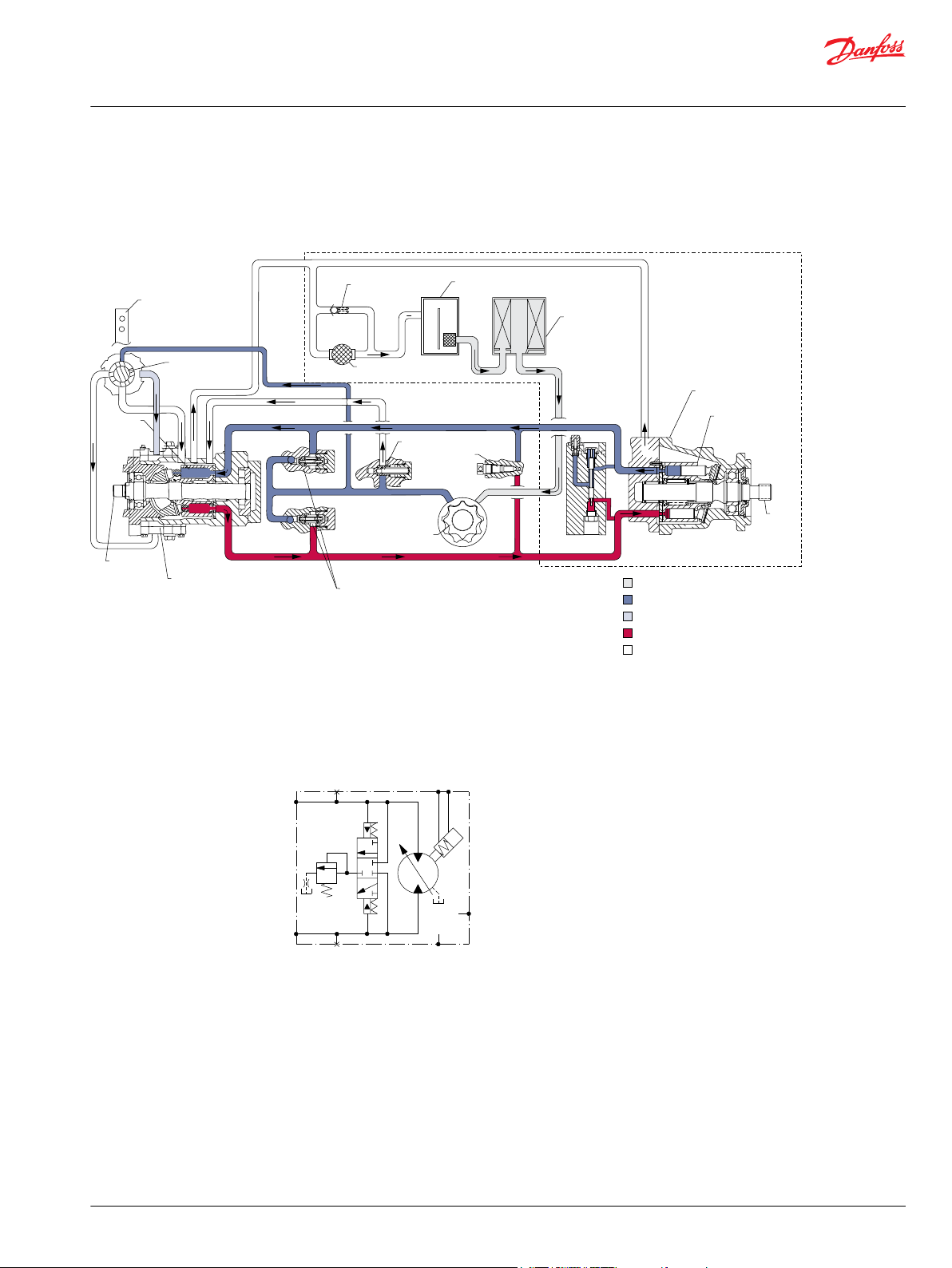
System circuit diagram
A Series 40 M35 fixed motor is shown in a hydraulic circuit with a Series 40 M46 variable pump. A loop
flushing module is included on the motor. The circuit features suction filtration and heat exchanger.
M46 motor schematic
The system ports (A and B) connect to the high pressure work lines. The motor receives pressurized fluid
in its inlet port and discharges de-energized fluid through the outlet port. Either port can act as inlet or
outlet; flow is bidirectional. System port pressure is gauged through ports M1 and M2. The motor has two
case drains (L1 and L2). The motor may include loop flushing. Loop flushing provides additional cooling
©
Danfoss | February 2017 520L0636 | 0703 | 7
and filtration capacity.

Technical Information
Series 40 Axial Piston Motors
Technical Specifications
Overview
Specifications and operating parameters are shown below. Not all hardware options are available for all
configurations. For additional information, see Operating Parameters on page 12, System design
parameters on page 14, Product coding on page 18, Features and options on page 20 and Control
options on page 28.
General
Product Line Series 40 motors
Product Type In-line, axial piston, fixed and variable, positive
Direction of Rotation Clockwise (CW) and counterclockwise (CCW)
Installation Position Discretionary, the housing must be filled with hydraulic
Filtration Configuration Suction or charge pressure filtration
Other System Requirements Independent braking system, circuit overpressure
displacement motors
fluid before operation
protection, suitable reservoir and heat exchanger
Features and options
Model M25 MF M35 MF M44 MF M35 MV M44 MV M46 MV
Type of mounting
Port connections
Output shaft
options
Control options
Loop flushing
Displacement
limiters
Speed sensors
SAE B SAE B SAE B SAE B SAE B SAE B
Twin, Axial Side, Twin, Axial Side, Twin, Axial Twin Twin Side, Twin, Axial
Splined, Tapered Splined, Tapered,
Straight Key
- - - DDC DDC Hyd. 2-pos.
Option Option Option Option Option Option
- - - Option Option Option
Option Option Option - - Option
Splined, Tapered,
Straight Key
Splined Splined Splined, Tapered
Specifications
Model Unit M25MF M35 MF M44 MF M35MV M44MV M46 MV
Model configuration - Fixed Fixed Fixed Variable Variable Variable
Type of mounting - SAE B SAE B SAE B SAE B SAE B SAE B
Displacement cm3/rev [in3/rev] 25 [1.50] 35 [2.14] 44 [2.65] 35 [2.14] 44 [2.65] 46 [2.80]
Weight kg [lbf] 11 [26] 11 [26] 11 [26] 21 [47] 21 [47] 23 [51]
Mass moment of inertia
kg•m2 [slug•ft2] 0.0018
[0.0013]
0.0033
[0.0024]
0.0032
[0.0023]
0.0033
[0.0024]
0.0032
[0.0023]
0.0050 [0.0037]
Operating parameters
Model M25 MF M35 MF M44 MF M35 MV M44 MV M46 MV
Case pressure bar [psi]
Maximum working 1.7 [25]
Maximum 5.2 [75]
Speed limits min-1[rpm]
Rated @ max disp. 4000 3600 3300 3600 3300 4000
8 | © Danfoss | February 2017 520L0636 | 0703

100
80
95
90
85
Efficienc
y -
%
0 25 50 75 100
Speed - % of Rated Speed
Volumetric Efficiency - 170 bar [2500 psi]
Volumetric Efficiency - 345 bar [5000 psi]
Overall Efficiency - 170 bar [2500 psi]
Overall Efficiency - 345 bar [5000 psi]
P100 455E
Technical Information
Series 40 Axial Piston Motors
Technical Specifications
Model M25 MF M35 MF M44 MF M35 MV M44 MV M46 MV
Maximum @ max. disp. 5000 4500 4100 4500 4100 4100
Rated @ min. disp. - - - 4200 3900 4500
Maximum @ min. disp.
System pressure bar [psi]
Maximum working 345 [5000] 380 [5511] 345 [5000] 380 [5511] 345 [5000] 345 [5000]
Maximum 385 [5584] 415 [6019] 415 [6019] 415 [6019] 415 [6019] 385 [5584]
Fluid specifications
Ratings and data are based on operation with premium petroleum-based hydraulic fluids reftaining
oxidation, rust, and foam inhibitors.
Parameter Unit Minimum reftinuous Maximum
Viscosity mm /sec (cSt)
Temperature °C [°F] -40 [-40] 82 [180] 104 [220]
Cleanliness ISO 4406 Class 18/13 or better
Filtration
efficiency
Hydraulic unit life
Hydraulic unit life is the life expectancy of the hydraulic components. Hydraulic unit life is a function of
speed and system pressure; however, system pressure is the dominant operating variable affecting
hydraulic unit life. High pressure, which results from high load, reduces expected life.
It is desirable to have a projected machine duty cycle with percentages of time at various loads and
speeds. Danfoss calculates appropriate design pressure from this information. This method of selecting
operating pressure is recommended whenever duty cycle information is available.
All pressure limits are differential pressures and assume normal charge pressure. Series 40 motors will
meet satisfactory life expectancy if applied within the parameters specified in this bulletin. For more
detailed information on hydraulic unit life see BLN9884 Pressure and Speed Limits.
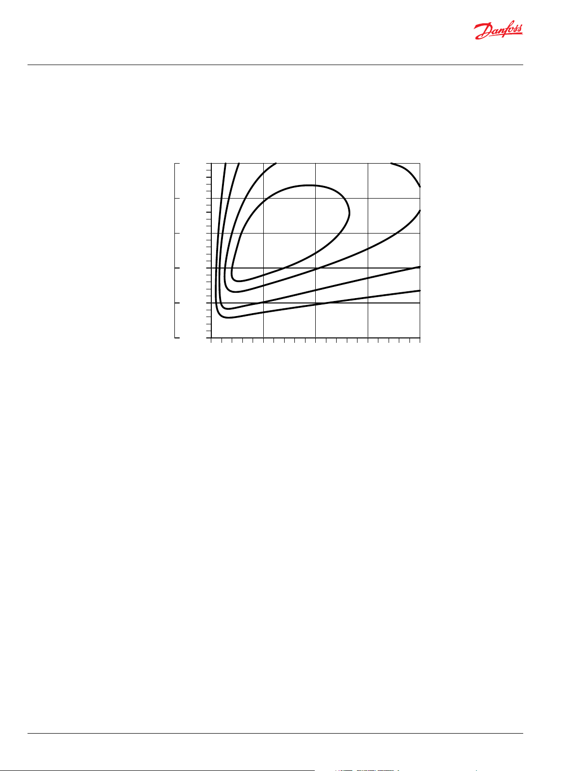
Performance
This performance graph provides typical volumetric and overall efficiencies for Series 40 motors. These
efficiencies apply for all Series 40 motors at maximum displacement.
Motor performance as a function of operating speed
- - - 5300 4850 5000
[SUS]
suction filtration β
charge filtration β
7 [47] 12-60 [70-278] 1600 [7500]
=75 (β10≥1.5)
35-44
=75 (β10≥10)
15-20
©
Danfoss | February 2017 520L0636 | 0703 | 9
5000
0
4000
3000
2000
1000
System Pressur
e
0 25 50 75 100
Speed - % of Rated Speed
psi
345
0
270
210
140
bar
70
80%
85%
88%
89%
8
0
%
85%
88%
89%
P100 456E
Technical Information
Series 40 Axial Piston Motors
Technical Specifications
The performance map provides typical motor overall efficiencies at various operating parameters. These
efficiencies apply for all Series 40 motors at maximum displacement.
Motor performance as a function of operating speed
Bearing life and external shaft loading
Bearing life is a function of speed, pressure and swashplate angle, plus any external loads. Other life
factors include oil type and viscosity.
In vehicle propulsion drives with no external loads, where the speed, pressure, and swashplate angle are
often changing, normal bearing ß10 (90% survival) life will exceed the hydraulic unit life.
In non-propel drives, such as conveyors or fan drives, the operating speed and pressure may be nearly
constant leading to a distinctive duty cycle compared to that of a propulsion drive. In propel applications,
Danfoss recommends a bearing life review.
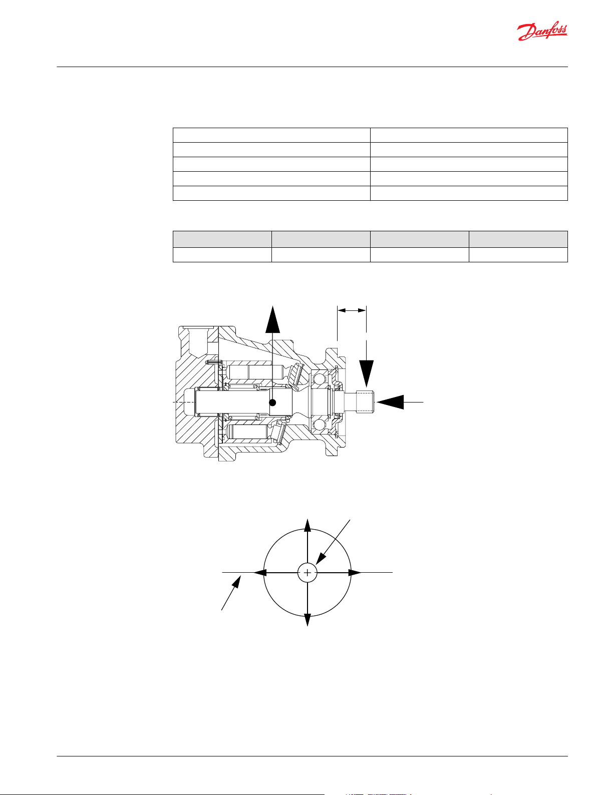
Series 40 motors are designed with bearings that can accept some incidental external radial and thrust
loads. However, any amount of external load will reduce the expected bearing life.
The allowable radial shaft loads are a function of the load position, the load orientation, and the
operating pressures of the hydraulic unit. All external shaft loads have an effect on bearing life. In motor
applications where external shaft loads cannot be avoided, the impact on bearing life can be minimized
by orienting the load to the 180 degree position (see Direction of external shaft load, next page).
The recommended maximum radial load (Re) is based on an external moment (Me) and the distance (L)
from the mounting flange to the load, (see table at below). The loads in the table reflect a worst case
external load orientation (0 degrees), a continuously applied working pressure of 140 bar (2000 psi), 20
bar (285 psi) charge pressure, 1800 min-1(rpm), and a bearing life (ß10) of 2000 hours. Avoid thrust loads
in either direction.
The recommended maximum allowable radial load is calculated as: Re = Me / L
If continuously applied external radial loads exceed the recommended maximum allowable, or thrust
loads are known to occur, contact Danfoss for an evaluation of unit bearing life. Optional high capacity
bearings are available.
Tapered output shafts or clamp-type couplings are recommended for applications where radial shaft side
loads are present.
10 | © Danfoss | February 2017 520L0636 | 0703
L
Re
F
B
T
P100 453E
0 Re
180 Re
90 Re 270 Re
Axis of swashplate
rotation
End vi
ew
of shaft
P100 454E
Technical Information
Series 40 Axial Piston Motors
Technical Specifications
Shaft loading parameters
R
e
M
e
L Distance from mounting flange to point of load
F
B
T Thrust load
Recommended maximum external shaft moments
Me N•m [lbf•in] 29 [255] 25 [225] 24 [215]
External shaft loads
Maximum radial side load
Maximum external moment
Force of block (applies at center of gravity)
M25 M35/44 M46
©
Danfoss | February 2017 520L0636 | 0703 | 11
Direction of external shaft load
W
Technical Information
Series 40 Axial Piston Motors
Operating Parameters
Fluids
Ratings and performance data are based on operating with premium hydraulic fluids containing
oxidation, rust, and foam inhibitors. These include premium turbine oils, API CD engine oils per SAE J183,
M2C33F or G automatic transmission fluids (ATF), Dexron™ II (ATF) meeting Allison™ C-3 or Caterpillar
T0‑2 requirements, and certain specialty agricultural tractor fluids. For more information on hydraulic
fluid selection, see Danfoss publications: 520L0463, Hydraulic Fluids and Lubricants, Technical Information,
and 520L465, Experience with Biodegradable Hydraulic Fluids, Technical Information.
Viscosity
Fluid viscosity limits
Condition mm2/s (cSt) SUS
Minimum 7 47
Continuous 12-60 70-278
Maximum 1600 7500
Maintain fluid viscosity within the continuous range for maximum efficiency and bearing life. Minimum
viscosity should only occur during brief occasions of maximum ambient temperature and severe duty
cycle operation. Maximum viscosity should only occur at cold start: Limit speeds until the system warms
up. See Danfoss publication: 520L0463, Hydraulic Fluids and Lubricants, Technical Information.
™
Temperature
Case pressure
Maintain fluid temperature within the limits shown in the table. Minimum temperature relates to the
physical properties of the component materials. Cold oil will not affect the durability of the motor
components. However, it may affect the ability of the motor to transmit
power. Maximum temperature is based on material properties. Don't exceed it. Measure maximum
temperature at the hottest point in the system. This is usually the case drain.
Ensure fluid temperature and viscosity limits are concurrently satisfied.
Temperature limits
Temperature limits
Minimum
(intermittent, cold start)
Continuous 82.2° C [180° F]
Maximum 104.4° C [220° F]
- 40° C [- 40° F]
Maintain case pressure within the limits shown in the table. Ensure housing is kept filled with hydraulic
fluid.
Case pressure limits
Maximum (continuous) 1.7 bar [25 psi]
Intermittent (cold start) 5.2 bar [75 psi]
Warning
Operating outside of case pressure limits will damage the motor. To minimize this risk, use full size inlet
and case drain plumbing, and limit line lengths.
12 | © Danfoss | February 2017 520L0636 | 0703

W
Technical Information
Series 40 Axial Piston Motors
Operating Parameters
System Pressure
System pressure is the differential pressure between high pressure system ports. It is the dominant
operating variable affecting hydraulic unit life. High system pressure, which results from high load,
reduces expected life. Hydraulic unit life depends on the speed and normal operating, or weighted
average, pressure that can only be determined from a duty cycle analysis.
Application pressure is the high pressure relief or pressure limiter setting normally defined within the
order code of the pump. This is the applied system pressure at which the driveline generates the
maximum calculated pull or torque in the application.
Maximum Working pressure is the highest recommended application pressure. Maximum working
pressure is not intended to be a continuous pressure. Propel systems with application pressures at, or
below, this pressure should yield satisfactory unit life given proper component sizing.
Maximum pressure is the highest allowable application pressure under any circumstance. Application
pressures above maximum working pressure will only be considered with duty cycle analysis and factory
approval.
Minimum low loop pressure must be maintained under all operating conditions to avoid cavitation.
All pressure limits are differential pressures referenced to low loop (charge) pressure. Subtract low loop
pressure from gauge readings to compute the differential.
Speed ratings
The table, Operating parameters on page 8, gives rated and maximum speeds for each displacement. Not
all displacements operate under the same speed limits. Definitions of these speed limits appear below.
Rated speed is the maximum recommended operating speed at full power condition. Operating at or
below this speed should yield satisfactory product life. In vehicle propel applications, maximum motor
speed during unloaded, on-road travel over level ground should not exceed this limit.
Maximum speed is the highest operating speed permitted. Exceeding maximum speed reduces motor
life and can cause loss of hydrostatic power and braking capacity. Never exceed the maximum speed
limit under any operating conditions.
Warning
Unintended vehicle or machine movement hazard
The loss of hydrostatic drive line power, in any mode of operation (forward, neutral, or reverse) may cause
the system to lose hydrostatic braking capacity. You must provide a braking system, redundant to the
hydrostatic transmission, sufficient to stop and hold the vehicle or machine in the event of hydrostatic
drive power loss.
Speed limits
Limit min-1(rpm) M25 MF M35 MF M44 MF M35 MV M44 MV M46 MV
Rated at max. displ. 4000 3600 3300 3600 3300 4000
Maximum at max. displ. 5000 4500 4100 4500 4100 4100
Rated at min. displ. - - - 4200 3900 4500
Maximum at min. displ... - - - 5300 4850 5000
©
Danfoss | February 2017 520L0636 | 0703 | 13

Base d on SI units
Input f ow Q = (l/m in)
Outp ut torque M = (N•m)
Outp ut power P = (kW)
Motor spe ed n = (min
-1
(rpm))
Base d on US units
Input f ow Q = (US gal/min)
Outp ut torque M = (lbf•in)
Outp ut power P = (hp)
Motor spe ed n = (min
-1
(rpm))
SI units [US units]
Vg= Displacement per revolut ion cm3/rev [in
3
/rev]
p
O
= Ou tlet pressure bar [psi]
pi= Inlet pressure bar [psi]
∆p = pO– p
i
(system pressure) bar [p si]
n = Spee d min-1(rpm)
ηv= Volumet ric eff ciency
ηm= Mechan ical eff ciency
ηt= Overall eff cie ncy (ηv• ηm)
Variables
V
g
• n
1000 •
η
v
Q • 1000 • η
v
V
g
V
g
• n
231 •
η
v
Vg• ∆p • η
m
20 • π
Q •∆p • η
t
600
Vg• ∆p • η
m
2 • π
Q •∆p • η
t
1714
Q • 231• η
v
V
g
Technical Information
Series 40 Axial Piston Motors
System design parameters
Sizing equations
Use the following equations to compute output power, torque, speed, and input flow. Selecting the right
motor starts with an evaluation of system requirements such as speed and torque. Select a motor that
will transmit the required torque, then select a pump that will meet the flow and pressure requirements
of the motor. For more information on hydrostatic drive selection, refer to Danfoss applications guideline
BLN-9885, Selection of Drive Line Components.
Filtration
To prevent damage to the system, including premature wear, fluid entering the motor must be free of
contaminants. Series 40 motors require system filtration capable of maintaining fluid cleanliness at ISO
4406-1999 class 22/18/13 or better.
Consider these factors when selecting a system filter:
Cleanliness specifications
•
Contaminant ingression rates
•
Flow capacity
•
Desired maintenance interval
•
The filter may be located either on the inlet (suction filtration) or discharge (charge pressure filtration)
side of the charge pump. Series 40 pumps are available with provisions for either suction or charge
pressure filtration to filter the fluid entering the charge circuit (see Loop flushing valve on page 15).
Typically, a filter with a beta ratio of β10 = 1.5 to 2.0 is adequate. However, open circuit systems supplied
from a common reservoir may have considerably higher requirements. Because each system is unique,
only a thorough testing and evaluation program can fully validate the filtration system. For more
Bypass valve
information, see Danfoss publication 520L0467, Design Guidelines for Hydraulic Fluid Cleanliness.
In some applications it is desirable to bypass fluid around the variable displacement pump, for example;
to allow a vehicle to move short distances at low speeds without running the prime mover. This is done
14 | © Danfoss | February 2017 520L0636 | 0703

W
15.14
[4.00]
11.36
[3.00]
3.79
[1.00]
0
8.62
[125]
12.07
[175]
15.51
[225]
Charge pressure bar [psi]
19.96
[275]
22.41
[325]
25.86
[375]
7.57
[2.00]
Fl
ow
l/min [US gal/min]
P100 643E
Technical Information
Series 40 Axial Piston Motors
System design parameters
by opening a manually operated bypass valve. This valve connects both sides of the pump/motor circuit
and allows the motor to turn. During normal operation, this valve must be fully closed .
Bypass valves are available in Series 40 pumps. See Danfoss publication: 520L0635, Series 40 Pumps
Technical Information.
Bypass valves are intended for moving a machine or vehicle for very short distances at very slow speeds.
They are NOT intended as tow valves.
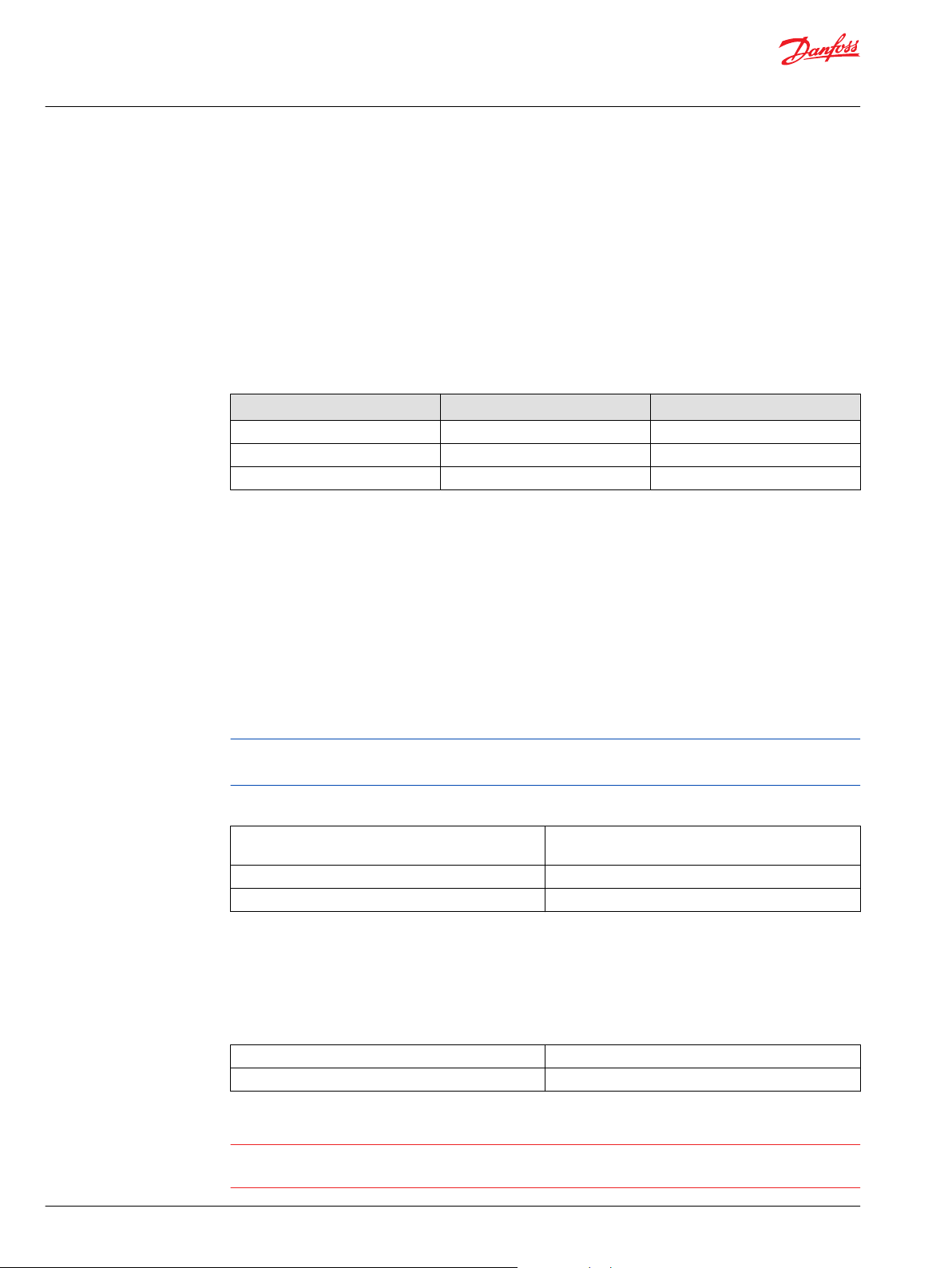
Loop flushing valve
Series 40 motors may incorporate an integral loop flushing valve. Installations that require additional
fluid to be removed from the main hydraulic circuit because of fluid cooling or cleanliness requirements,
will benefit from loop flushing. A loop flushing valve will remove heat and contaminants from the main
loop at a rate faster than otherwise possible. Contact your Danfoss representative for production
availability on specific frame size motors.
Series 40 loop flushing valves include a loop flushing relief valve with integral orifice. The flushing flow is
a function of the pump charge relief valve, and the orifice size.
Loop flushing flows of 3 to 7 l/min [0.75 to 2 US gal/min] are adequate for most applications. Contact
your Danfoss representative for assistance.
Warning
Incorrect charge pressure settings may result in the inability to build required system pressure and/or
inadequate loop flushing flows. Maintain correct charge pressure under all conditions.
Typical loop flushing flow as a function of charge pressure
©
Danfoss | February 2017 520L0636 | 0703 | 15

Loop flushing
relief valve
with orifice
Loop flushing
shuttle valve
P100 448E
W
Technical Information
Series 40 Axial Piston Motors
System design parameters
Loop flushing valve
Charge Flow
Closed circuit operations require a charge pump to make up for lubrication and cooling losses, and to
charge the low pressure side of the system loop. The total charge flow required is a sum of the charge
flow requirements for the pump, plus the flow requirements for all motors in the system, plus any
external loop flushing requirements. Ensure that adequate charge flow exists under all conditions of
engine speed and motor speed and pressure.
Charge Pressure/Open Circuit Operation
M35 and M44 motors can be operated with zero pressure in the low side of the system loop. The case
pressure must not be higher than 2 bar over the low side of the loop system pressure. With zero back
pressure, the maximum allowed case pressure is 2 bar [29 psi]. Case drain lines must be plumbed
accordingly to insure this 2 bar case pressure differential is not exceeded under any circumstances.
Redundant braking system requirement
Warning
Unintended vehicle or machine movement hazard.
The loss of hydrostatic drive line power, in any mode of operation (forward, neutral, or reverse) may cause
the system to lose hydrostatic braking capacity. You must provide a braking system, redundant to the
hydrostatic transmission, sufficient to stop and hold the vehicle or machine in the event of hydrostatic
drive power loss.
Reservoir
The reservoir provides clean fluid, dissipates heat, and removes entrained air from the hydraulic fluid. It
allows for fluid volume changes associated with fluid expansion and cylinder differential volumes.
Minimum reservoir capacity depends on the volume needed to perform these functions. Typically, a
capacity of one half the charge pump flow (per minute) is satisfactory for a closed reservoir. Open circuit
systems sharing a common reservoir will require greater fluid capacity.
Locate the reservoir outlet (suction line) near the bottom, allowing clearance for settling foreign particles.
Use a 100 - 125 µm screen covering the outlet port. Place the reservoir inlet (return lines) below the
lowest expected fluid level, as far away from the outlet as possible. Use a baffle (or baffles) between the
reservoir inlet and outlet ports to reduce aeration and fluid surging.
16 | © Danfoss | February 2017 520L0636 | 0703

C
Technical Information
Series 40 Axial Piston Motors
System design parameters
Overpressure protection
Series 40 motors (as well as other system components) have pressure limits. Relief valves or pressure
limiters should be present in the high pressure circuit to protect components from excessive pressures.
High pressure relief valves are intended for transient overpressure protection and are not intended for
continuous pressure control. Operation over relief valves for extended periods of time may result in
severe heat build up. High flows over relief valves may result in pressure levels exceeding the nominal
valve setting and potential damage to system components.
Caution
©
Danfoss | February 2017 520L0636 | 0703 | 17

Name plate
Place of manufacture
Model
number
Serial
number
Model
code
Made in USAMade in USA
Model-No/Ident-No.Model-No/Ident-No.
R NN A A BLL DR A
FF A CNN
MMV 046 C B A B A AMMV 046 C B A B A A
R NN A A BLL DR A
FF A CNN
Model CodeModel Code
Serial-NoSerial-No
A - 96 - 26 - 12345A - 96 - 26 - 12345
M46-2001
M46-2001
P101372
M
M
V
S
4
6 C
Product
Displacement
Type
C
D E F G
T
Z
*
*
*
-
-
-
- -
P104 427E
M
M
V
S
4
6 C
Product
Displacement
Type
C
D E F G
T
Z
*
*
*
-
-
-
- -
P104 427E
Technical Information
Series 40 Axial Piston Motors
Product coding
Revised model code
The model code is a modular description of a specific product and its options. To create an order code to
include the specific options desired, see the Series 40 Motor Model Code Supplement 520L0636MC.
Model code modules
Fixed motor
C Seal group
D Output shaft/through shaft configuration
E Endcap configuration
F Cylinder block group
G Housing configuration
T Special hardware features
Z Special features (non-hardware) *** = None
Variable motor
C Seal group
D Output shaft/through shaft configuration
E Endcap configuration
F Control features
G Housing configuration
18 | © Danfoss | February 2017 520L0636 | 0703

Technical Information
Series 40 Axial Piston Motors
Product coding
T Special hardware features
Z Special features (non-hardware) *** = None
©
Danfoss | February 2017 520L0636 | 0703 | 19

P108697
L1
L2
M1
A
B
Optional
M2
L1
L2
M1
A
B
Optional
M2
Anti-Cavitation Valve, Port A High Pressure
Rotation Clockwise - M25 Fixed Motor
Anti-Cavitation Valve, Port B High Pressure
Rotation Counterclockwise
M35/M44 Fixed Motor
Technical Information
Series 40 Axial Piston Motors
Features and options
Anti-Cavitation Valve Option
The M25, M35 and M44 fixed motors are available with an anti-cavitation valve option. The key
application for this option is open circuit fan drives.
The anti cavitation valve combines the function of a shock valve and check valve within the same cavity
which is integrated into the endcap. The check valve function provides protection against cavitation that
can occur upon introduction of an overrunning load or due to loss of input flow. In such case, the system
delta pressure becomes negative and the check valve opens connecting the motor inlet and outlet,
effectively short-circuiting the motor. The shock valve function is intended to be used for system overpressure protection events of limited duration only. It is not intended for continuous system pressure
limitation.
The shock valve is available with 280 bar or 345 bar setting.
For this option the high pressure port needs to be defined upfront to get the correct motor rotation.
Reversing the motor is not possible with this option.
Flow direction
Motor shaft rotation Port A Port B Special Hardware Feature
Clockwise (CW) In Out NCD/NCF
Counterclockwise (CCW) Out In NCE/NCG
Displacement limiters
M35, M44, and M46 variable motors have minimum displacement limiters. Minimum unit displacement
is obtained with the adjuster screw at its maximum extension from the end cap or displacement control
piston cover. All motors are shipped with the displacement limiter set for minimum motor displacement.
The M35 and M44 MV minimum displacement limiter is located in the end cap. The M46 MV minimum
displacement limiter is located in the displacement control piston cavity. The length and configuration of
this limiter will depend upon the control option installed in the motor.
M46 MV units may have an optional mechanical maximum displacement limiter located in the
displacement control piston cover. The maximum displacement limit can be adjusted by loosening the
20 | © Danfoss | February 2017 520L0636 | 0703

W
Swashplate
Displacement limiter
P100 449E
Sealing locknut
P100 450E
Fixed minimum
displacement limiter
Adjustable minimum
displacement limiter
Adjustable maximum
displacement limiter
Technical Information
Series 40 Axial Piston Motors
Features and options
sealing lock nut, adjusting displacement by rotating the screw with a screwdriver, then locking the
adjuster by torquing the sealing lock nut.
Maximum unit displacement is obtained with the adjuster screw standing at its maximum height out of
the displacement control piston cover. All motors are shipped with the limiter set for maximum motor
displacement.
Undesirable output speed hazard.
Take care adjusting displacement limiters. Too low of a minimum displacement setting can result in
higher than expected output speed. Retorque the sealing locknut after every adjustment to prevent an
unexpected changes and to prevent external leakage.
Displacement limiter M35/M44 MV
Warning
Speed sensor option
©
Danfoss | February 2017 520L0636 | 0703 | 21
Displacement limiter M46 MV
Series 40 motors are available with a speed sensor option for direct measurement of motor output speed.
You can use this sensor may to sense the direction and speed of motor rotation.
A special magnetic speed ring is pressed onto the outside diameter of the cylinder block. A hall effect
pulse pickup is located in the motor housing. The sensor accepts supply voltage and outputs a digital

Speed sensor
Magnetic ring
Cylinder block
P100 452E
Technical Information
Series 40 Axial Piston Motors
Features and options
pulse signal in response to the speed of the ring. The output changes its high/low state as the north and
south poles of the permanently magnetized speed ring pass by the face of the sensor. The digital signal is
generated at frequencies suitable for microprocessor based controls.
This sensor will operate with a supply voltage of 4.5 to 15 Vdc, and requires a current of 12 mA at 5.0 Vdc
(minimum) under no load. Maximum operating current is 20 mA at 5 Vdc (maximum). Maximum
operating frequency is 15 kHz. Output voltage in High State (VOH) is sensor supply voltage minus 0.5 Vdc,
minimum. Output voltage in Low State (VOL) is 0.5 Vdc, maximum. The sensor is available with a Packard
Weather-Pack™ or 4-pin sealed connector.
Contact your Danfoss representative for production availability on specific motor frame sizes, or for
special speed sensor options.
Speed sensor specifications
Supply voltage 4.5 - 15 Vdc
Required current 12 mA @ 5 Vdc
Maximum current 20 mA @ 5Vdc
Maximum frequency 15 kHz
VOH Supply Vdc - 0.5 Vdc
VOL 0.5 Vdc maximum
Magnetic ring
Pulses/revolution
Connector Packard Weather-PackTM
(no load)
M25 M35 M44 M46
43 46 46 51
3- pin, 4-pin
Speed sensor cross section
22 | © Danfoss | February 2017 520L0636 | 0703

Red
Red
White
Black
Black
Green
Supp ly voltage +
Supp ly voltage +
Spee d sig nal
Spee d sig nal
Direction
Ground common
Ground common
A
A
B
B
C
C
D
Packard Weather-Pack
4 pin tower conne ctor
3 pin Weather-Pack
shroud
White
TM
TM
Mating parts kit part number K03379 (4 pin)
Mating parts kit part number K20582 (3 pin)
Speed sensor with directional signal
Speed sensor without directional signal
Technical Information
Series 40 Axial Piston Motors
Features and options
Pulse pickup and connector
Shaft options
Shaft availability and torque ratings
N•m [lbf•in] M25 MF M35 MF M44 MF M35 MV M44 MV M46 MV
Spline
13-tooth,
16/32 pitch
©
Danfoss | February 2017 520L0636 | 0703 | 23
Series 40 motors are available with a variety of splined, straight keyed, and tapered shaft ends. Nominal
shaft sizes and torque ratings for some available shafts are shown in the accompanying table. Other shaft
options may exist. Contact your Danfoss representative for availability.
Shaft torque for tapered shafts
The rated torque is based on the contact pressure between the shaft and hub surfaces with poor surface
contact areas. With an increased quality of the contact areas, the contact pressure between the shaft and
hub is increased and allows higher torque to be transmitted.
Torque ratings assume no external radial loading. Continuous torque ratings for splined shafts are based
on spline tooth wear, and assume the mating spline has a minimum hardness of Rc 55 to full spline depth
and coupling has good lubrication.
Maximum torque ratings are based on shaft torsional strength and assume a maximum of 200,000 load
reversals.
Continuous 80 [750] 73 [650] 73 [650] 73 [650] 73 [650] 73 [650]
Max 40 [1240] 226 [2000] 226 [2000] 226 [2000] 226 [2000] 226 [2000]

W
Technical Information
Series 40 Axial Piston Motors
Features and options
Shaft availability and torque ratings (continued)
N•m [lbf•in] M25 MF M35 MF M44 MF M35 MV M44 MV M46 MV
Spline
15-tooth,
16/32 pitch
Spline
19-tooth
16/32 pitch
Tapered 1.00 inch Max 140 [1240] 497 [4400] 497 [4400] - - 497 [4400]
Straight keyed 0.875 inch Max - 226 [2000] 226 [2000] - - -
Through-shaft options
Continuous - 153 [1350] 153 [1350] 153 [1350] 153 [1350] 153 [1350]
Max - 362 [3200] 362 [3200] 362 [3200] 362 [3200] 362 [3200]
Continuous - - - - - 194 [1710]
Max - - - - - 460 [4070]
Recommended mating splines for Series 40 splined output shafts should be in accordance with ANSI
B92.1 Class 5. Danfoss external splines are modified Class 5 Fillet Root Side Fit. The external spline Major
Diameter and Circular Tooth Thickness dimensions are reduced in order to assure a clearance fit with the
mating spline.
Optional through-shafts are available on Series 40 fixed and variable displacement motors (as noted in
the accompanying table). Through-shafts are provided for use in secondary (parking) braking systems.
Through-shaft ends are not intended for continuous power transmission.
Through-shaft availability and torque limitations
Frame size Shaft spline Max. torque limit
N•m [lbf•in]
M35 MF 13T 16/32 P 328 [2900]
M44 MF 13T 16/32 P 328 [2900]
M46 MV(SAE) 13T 16/32 P 328 [2900]
Warning
Potential loss of braking capacity.
Exceeding these torque limits could cause shaft breakage. Ensure your application never exceeds
maximum torque limits under any operating conditions.
24 | © Danfoss | February 2017 520L0636 | 0703

20.638 [0.8125] pitch dia.
30° pressure angle
13 teeth,16/32 pitch
fillet root side fit
per ANSI B92.1 class 5
also mates with
flat root side fit
21.717 dia.
[0.8550]
18.8 max.
[0.74]
16.5 [0.65]
Full spline
7.9 [0.31]
33.32 max.
[1.312]
Coupling must not protrude
beyond this surface
Mounting
flange
(ref.)
P104 428E
0.750-16 UNF-2A thd.
22.22 Gauge dia.
[0.875]
38.1 [1.500] taper per foot
per SAE J5001
25.4 [1.000] nominal shaft dia.
3.81 max. [0.150]
6.30 x 22.22 dia. Woodruff key
[0.248x0.875]
0.25 [0.01] min. R on edges
33.3 Gauge dim.
[1.311]
42.8 [1.68]
27 [1.06]
Coupling must not
protrude beyond
25.4 max. [1.000]
Mounting
flange
(ref.)
P104 429E
22.22 Gauge dia.
[0.875]
3.8 max.
[0.15]
6.30 x 22.22 dia. Woodruff key
[0.248 x 0.875]
0.25 [0.01] min. R. on edges
48.47 ± 1.12
[1.908 ± 0.44]
26.97
[1.06]
Coupling must not
protrude beyond
this point
Mounting
flange
P108 717E
3/4-16
UNF Thd.
9.17 ± 0.38
[0.361 ± 0.015]
Gauge dimension
13.47 ± 0.99
[0.53 ± 0.039]
T dia.
V dia.
W pitch dia.
30° pressure angle
Y teeth, Z pitch
fillet root side fit
per ANSI B92.1-1970 class no.5
also mates with flat
root side fit
S
7.65 [0.301]
U
Coupling must not
protrude beyond
this surface
Mounting
flange
(ref.)
P104 430E
Technical Information
Series 40 Axial Piston Motors
Shaft options
M25 MF
Code Description Torque rating N•m [lbf•in] Drawing
Max. torque rating Cont. torque rating
E
13-tooth
16/32 pitch
(ANSI B92.1 1970 - Class
5)
140 [1240] 80 [750]
N
Ø 25.4 mm [1.000 in]
140 [1240] —
1:8 taper
D
Ø 25.4 mm [1.000 in]
140 [1240] —
1:8 taper - with dust seal
M35/44 MF
Code Description Torque rating Drawing
Maximum torque
rating N•m [lbf•in]
A, C Splined output shaft
F 15 tooth 362 [3200] 15 tooth 153 [1350]
(see table)
13 tooth 226 [2000] 13 tooth 73 [650]
Continuous torque
rating N•m [lbf•in]
©
Danfoss | February 2017 520L0636 | 0703 | 25

0.750-16 UNF-2A thd.
22.22 gauge dia.
[0.875]
38.1 [1.500] taper per foot
per SAE J501
25.4 [1.000] nominal shaft dia.
3.81 max. [0.150]
6.30 x 22.22 dia. Woodruff key
[0.248 x 0.875]
0.25 [0.01] min. R on edges
33.3 gauge dim.
[1.311]
42.8 [1.68]
27 [1.06]
Coupling must not
protrude beyond
25.4 max. [1.000]
Mounting
flange
(ref.)
P104 431E
Coupling must not
protrude beyond
this surface
7.65 [0.301]
22.2 dia.
[0.874 ± 0.001]
2.84 max.
[0.112]
6.35 [0.250] sq. key
38.1 [1.500] long
0.38 [0.015] min. R
on edges
64.74 ±0.025
[2.549] ±0.64
9.4 [0.37]
Mounting
flange
(ref.)
P104 432E
± 0.03
T dia.
V dia.
W pitch dia.
30° pressure angle
Y teeth, 16/32 pitch
fillet root side fit
per ANSI B92.1 class no.5
also mates with flat
root side fit
S
U
Coupling must not
protrude beyond
this surface
7.87
[0.310]
Mounting
flange
(ref.)
P104 433E
Technical Information
Series 40 Axial Piston Motors
Shaft options
M35 / M44 MF splined shaft option
Shaft option Shaft lengthSShaft
diameter
T
A 33.55 [1.321] 18.8 [0.74] 16.5 [0.65] 21.72 [0.8550] 20.638 [0.8125] 13 16/32 C 33.55 [1.321] 18.8 [0.74] 16.5 [0.65] 21.72 [0.8550] 20.638 [0.8125] 13 16/32 13T
F 33.55 [1.321] 21.98 [0.865] 18.5 [0.73] 24.89 [0.9800] 23.812 [0.9375] 15 16/32 -
Code Description Torque rating Drawing
Maximum torque
rating N•m [lbf•in]
N
Ø 25.4 mm [1.000 in]
497 [4400] —
1:8 taper
Full spline
U
Major dia.
V
Continuous torque
rating N•m [lbf•in]
Pitch dia.
W
No. teeth
Y
Pitch
Z
Thru shaft
S
Ø 22.2 mm [0.874 in]
226 [2000] —
straight keyed
M35/44 MV
Code Description Torque rating Drawing
Maximum torque
rating N•m
[lbf•in]
A Splined output shaft
73 [650] 226 [2000]
(see table)
26 | © Danfoss | February 2017 520L0636 | 0703
Continuous
torque rating
N•m [lbf•in]

W pitch dia.
30° pressure angle
Y teeth, Z pitch
fillet root side fit
per ANSI B92.1 class no.5
also mates with flat
root side fit
V dia.
U Full Spline
S max.
T max. dia.
7.47 [0.294]
Mounting
flange
(ref.)
Coupling must not protrude
beyond this surface
R
P104 434E
5.05 [0.199]
6.30 x 22.22 dia. woodruff key
[0.248 x 0.875]
1/8 taper [1.500 per foot]
per SAE standard J501
25.4 [1.000] nominal shaft dia.
37.62
[1.481]
36.58 [1.440]
max.
26.97
[1.062]
9.17 gauge dim.
[0.361]
Coupling must not protrude
beyond this surface
3/4 - 16 Thd.
22.22 [0.875]
gauge dia.
Mounting
flange
(ref.)
P104 435E
Technical Information
Series 40 Axial Piston Motors
Shaft options
M35 / M44 MV splined shaft option
Shaft option Max. coupling
engagement
S
A 33.3 [1.31] 18.8 [0.74] 16.5 [0.65] 21.72 [0.855] 20.638 [0.8125] 13 16/32 -
M46 MV
Code Description Torque rating Drawing
A, B, Splined output shaft
E, F, 15 tooth 362 [3200] 15 tooth 153 [1350]
D
(see table)
Shaft
diameter
T
Maximum torque
rating N•m [lbf•in]
Full spline
length
U
Major dia.
V
Continuous torque
rating N•m [lbf•in]
13 tooth 226 [2000] 13 tooth 73 [650]
19 tooth 460 [4070] 19 tooth 194 [1710]
Pitch dia.
W
No. teeth
Y
Pitch Thru shaft
J 25.4 [1.000] tapered
— 497 [4400]
shaft
M46 MV splined shaft option
Shaft option Shaft
extension
R
A 32.94 [1.297] 32 [1.26] 19.1 [0.75] 15.8 [0.62] 21.72 [0.855] 20.638
B 32.94 [1.297] 32 [1.26] 19.1 [0.75] 15.8 [0.62] 21.72 [0.855] 20.628
E 37.72 [1.485] 36.6 [1.44] 22.3 [0.88] 22.86 [0.90] 24.89 [0.980] 23.812
F 37.72 [1.485] 36.6
D 37.72 [1.485] 36 [1.44] 28.4 [1.114] 22.35 [0.88] 31.24 [1.230] 30.162
©
Danfoss | February 2017 520L0636 | 0703 | 27
Max.
coupling
engagement
Shaft
diameter
T
Fullspline
length
U
Major dia.VPitch dia.WNo. teethYPitch
S
13 16/32 ---
[0.8125]
13 16/32 13T
[0.8125]
15 16/32 ---
[0.9375]
[1.44]
22.3 [0.88] 22.86 [0.90] 24.89 [0.980] 23.812
[0.9375]
15 16/32 13T
19 16/32 ---
[1.1875]
Contact Danfoss Application Engineering for specific installation drawings.
Z
Thru shaft

W
Minimum
swashplate angle
16° for M35
16° for M44
P100 457E
100%
Min.
Trunnion rotation
Mo
to
r
displacemen
t
P100 458E
Technical Information
Series 40 Axial Piston Motors
Control options
Direct displacement control (DDC)
Unintended vehicle movement hazard.
Internal forces may not return the swashplate to the neutral position under all operating conditions.
The direct displacement control is available on either side of the M35 and M44 variable motors. It
provides a simple, positive method of displacement control. Movement of the control shaft causes a
proportional swashplate movement, thus varying the motor's displacement from full to minimum
displacement.
Neutral position is not factory set, nor is there any internal neutral return mechanism. The application
must include provisions for all control linkage and neutral return functionality.
External Control Handle Requirements
Maximum allowable trunnion torque is 79.1 N•m [700 lbf•in]. Minimum torque necessary to hold the
swashplate per 70 bar of differential system pressure is 11.3 N•m [100 lbf•in]. Maximum trunnion angle is
16° for M35 and M44.
DDC on left side of M35 motor
Warning
Motor displacement vs swashplate rotation
DDC input specifications
Max. torque N•m [lbf•in] 79.1 [700]
Min. torque to hold (per 70 bar
[1000 psi] system pressure)
N•m [lbf•in]
Max. angle 16°
11.3 [100]
28 | © Danfoss | February 2017 520L0636 | 0703

Port X1
Control pressure supply
(for minimum displacement)
Port X2
Control pressure supply
(for maximum displacement)
Top
Bottom
Single-line control
Two-line control
Technical Information
Series 40 Axial Piston Motors
Control options
Two-position hydraulic control
Series 40 M46 variable displacement motors are equipped with a hydraulically controlled swashplate. The
motor is spring biased toward maximum displacement. A hydraulic piston is used to shift the swashplate
from maximum to minimum displacement. A single or two-line control can regulate the servo piston.
With the standard single-line control option, hydraulic pressure is supplied to the control port (X1) to
shift the motor to minimum displacement. The opposite end of the displacement control piston
internally drains to the motor case. The swashplate shifts with a minimum pressure of 13.8 bar [200 psi].
The bias spring returns the motor to maximum displacement when control pressure is removed.
The single-line control generally uses a customer supplied 2-position, 3-way control valve. Hydraulic
pressure on the control piston must not exceed 27.6 bar [400 psi].
In applications which encounter frequent shifting on-the-go as part of the normal duty cycle, we
recommend the optional two-line control. Applications with routine shifting from work range to travel
range may not require the two-line control. to command minimum displacement, port control pressure
to port X1 and drain port X2. To command maximum displacement, port control pressure to port X2 and
drain port X1.
The two-line control generally uses a customer supplied 2-position, 4-way control valve. Hydraulic
pressure on the control piston must not exceed 27.6 bar (400 psi).
Orifices in either (or both) the control valve supply and drain lines optimize the shift rate for either the
single or two-line control. Contact your Danfoss representative for additional information.
Input specifications bar [psi]
Single line control Two line control
Max. pressure on control 27.6 [400] 27.6 [400]
Min. pressure to shift 13.8 [200] 13.8 [200]
Control valve
(customer supplied)
2-position / 3 way 2-position / 4-way
M46 2-position hydraulic controls
©
Danfoss | February 2017 520L0636 | 0703 | 29

Technical Information
Series 40 Axial Piston Motors
Installation drawings
M25 MF: axial ports, twin ports, loop flushing, speed sensor
Flow direction
Motor shaft rotation Port A Port B
Clockwise (CW) In Out
Counterclockwise (CCW) Out In
30 | © Danfoss | February 2017 520L0636 | 0703

65.91
[2.595]
26.67 [1.050]
7/8 - 14*
Port A (Twin)
7/8 - 14*
Port B (Twin)
78.9
[3.11]
64.26 [2.530]
26.67 [1.050]
25.4 [1.000]
56.9
[2.24]
64.8 [2.55]
162.8
[6.41]
134.5
[5.29]
64.97
[2.558]
101.57
[3.999]
3/4 - 16 SAE*
case outlet L1
76.7
[3.02]
9.4
[0.37]
48.8
[1.92]
7/16 - 20 UNF*
System pressure
gauge ports M1, M2
3/4 - 16*
case outlet
(alternate) L2
3.89
[98.9]
Loop flushing
relief valve
Loop flushing
shuttle valve
143.0
[5.63]
Speed sensor option
7/8 - 14*
Port A (Axial)
7/8 - 14*
Port B (Axial)
94.488
[3.72]
P100565E
Axial or Twin Ports
With Loop Flushing
Packard Weather-pack
4-way connector (male)
mates with
Packard part no. 12015797
4-way tower (female)
or
Danfoss kit no. K03384
Technical Information
Series 40 Axial Piston Motors
Installation drawings
©
Danfoss | February 2017 520L0636 | 0703 | 31

87.2
[3.44]
(2) places
73.02
[2.875]
(2) places
14.27 [0.562] dia.
(2) places
CW
CCW
P100566E
66.55 [2.620]
Case drain - L1 and L2
both sides
70.36
[2.77]
(2) places
87.25
[3.435]
(2) places
14.27 dia.
[0.562] (2) places
Approx. center of
gravity
CW
CCW
4.06
[0.16]
P100569E
Technical Information
Series 40 Axial Piston Motors
Installation drawings
*All ports are SAE straight thread o-ring ports per SAE J514, unless otherwise specified.
Shaft rotation is determined by viewing motor from output shaft end.
Contact Danfoss Application Engineering for specific installation drawings.
M25 MF: mounting flange
M35/M44 MF: mounting flange
*All ports are SAE straight thread o-ring ports per SAE J514, unless otherwise specified.
Shaft rotation is determined by viewing motor from output shaft end.
Contact Danfoss Application Engineering for specific installation drawings.
32 | © Danfoss | February 2017 520L0636 | 0703

77.1
[3.04]
79.5
[3.13]
71.9
[2.83]
Port A
77.7
[3.06]
(2) Places
Port B
7/16 -20*
System pressure
gauge port - M1
7/16 -20*
System pressure
gauge port - M2
23.9
[0.94]
(2) Places
Loop flushing
valve (option)
78.2
[3.08]
1-1/16 -12
(2) places
154.6
[6.08]
186.3
[7.34]
92.1
[3.63]
12.8
[0.51]
99.1
[3.90]
Loop flushing
shuttle valve (option)
P100567E
44.4
[1.75]
71.9
[2.83]
84.8
[3.34]
1-1/16 -12
O-ring boss
Per SAE J514
(2) places
40.1
[1.58]
(2) places
184.9
[7.28]
186.8
[7.34]
30.
5
[1.200]
7/8 -14
Case drain - L3
O-ring boss
Per SAE J514
Axial Ported Endcap
Twin Ports
92.1
[3.62]
7/8 -14
Alternate case drain - L2
O-ring boss
Per SAE J514
Technical Information
Series 40 Axial Piston Motors
Installation drawings
M35/M44 MF: axial ports, twin ports, loop flushing, speed sensor
Flow direction
Motor shaft rotation Port A Port B
Clockwise In Out
Counterclockwise Out In
©
Danfoss | February 2017 520L0636 | 0703 | 33
*All ports are SAE straight thread o-ring ports per SAE J514, unless otherwise specified.
Shaft rotation is determined by viewing motor from output shaft end.
Contact Danfoss Application Engineering for specific installation drawings.

P108708E
72.2
[2.84]
77.7
[3.06]
Port B
Port A
28.6
[1.13]
(2x)
(2x)
Anti-Cavitation
Valve Port B
7/16-20 Str. Thd.
O-ring boss
Per SAE J514
System Pressure
Gauge Port - M2
23.9
[0.94]
76.3
[3.00]
(2x)
7/16-20 Str. Thd.
O-ring boss
Per SAE J514
System Pressure
Gauge Port - M1
Anti-Cavitation
Valve Port A
78.1
[3.07]
187.1
[7.37]
155.3
[6.11]
Ports
A
and
B
6.63 ± 0.635
[0.261 ± 0.025]
39.35
± 0.635
Coupling must not
protrude beyond
this surface
6.35
+ 0.000
[0.312]
- 0.002
+ 0.00
7.89
- 0.05
Sq. Key.
25.4 [1.00] long
R. 0.5 [0.02]
on edges
3.4 [0.133] Max.
28.55 ± 0.03
[1.124 ± 0.001]
Ø
155.3
[6.11]
Technical Information
Series 40 Axial Piston Motors
Installation drawings
M35/M44 MF: radial ports, twin ports, anti-cavitation valve
*All ports are SAE straight thread o-ring ports per SAE J514, unless otherwise specified.
Shaft rotation is determined by viewing motor from output shaft end.
Contact Danfoss Application Engineering for specific installation drawings.
34 | © Danfoss | February 2017 520L0636 | 0703

186.3
[7.34]
184.9
[7.28]
17.8
[0.70]
154.6
[6.09]
161.3
[6.35]
1-1/16 -12*
(2) places
92.1
[3.63]
12.8
[0.51]
99.1
[3.90]
Approx center
of gravity
7/8 -14*
Case drain - L2
67.3
[2.65]
(2) places
89.7
[3.53]
71.9
[2.83]
77.7
[3.06]
(2) places
65.9
[2.60]
(2) places
7/8 -14*
Case drain - L3
44.5
[1.75]
Port B
Port A
Aux. shaft option
20.638 [0.8125] pitch diameter
30° pressure angle
13 teeth, 16/32 pitch
fillet root side fit
ANSI B92.1-1790 class no. 5
also mates with flat root side fit
161.3
[6.35]
184.0
[7.25]
218.29
[8.594]
1-1/16 -12*
(2) places
21.72
[0.855]
21.1 [0.83]
Fulll spline length
36.8 max.
[1.45]
Coupling must not
protrude beyond
this surface
6.3
[0.25]
151.00
[5.95]
7/8 -14*
Case drain - L3
29
[1.14]
(2) Places
67.3
[2.63]
89.7
[3.53]
71.9
[2.83]
70.5
[2.77]
50.813
[2.000]
65.91
[2.60]
1/2 -13 Thd.
92 [23.3] min. full Thd.
(2) places
67.3
[2.63]
92.1
[3.63]
12.8
[0.51]
99.1
[3.90]
Approx. center
of gravity
7/8 -14*
Case drain - L2
P100568
Side Ports
Side Ports with thru shaft
Auxiliary drive spline data:
Technical Information
Series 40 Axial Piston Motors
Installation drawings
M35/M44 MF: side ports, through shaft
*All ports are SAE straight thread o-ring ports per SAE J514, unless otherwise specified.
Shaft rotation is determined by viewing motor from output shaft end.
Contact Danfoss Application Engineering for specific installation drawings.
©
Danfoss | February 2017 520L0636 | 0703 | 35

164.7
[6.48]
96.4
[3.80]
1-1/16 -12*
Case outlet
1-1/16 -12*
Port A
1-1/16 -12*
Port B
35
[1.38]
35
[1.38]
95
[3.74]
7.6
[0.301]
16° max.
Disp.
min.
Disp.
66.7
[2.63]
12.6
[0.50]
Port B
Port A
9/16 -18*
system pressure
gauge Port M1
Displacement
limiter
9/16 -18*
System pressure
gauge Port M2
92.2
[3.63]
96.5
[3.80]
80.5
[3.17]
101.57
[3.999]
P100570E
Technical Information
Series 40 Axial Piston Motors
Installation drawings
M35/M44 MV: twin ports
*All ports are SAE straight thread o-ring ports per SAE J514, unless otherwise specified.
Shaft rotation is determined by viewing motor from output shaft end.
Contact Danfoss Application Engineering for specific installation drawings.
36 | © Danfoss | February 2017 520L0636 | 0703

CW
CCW
125
[4.92]
111.
8
[4.40]
70.4
[2.77]
Control trunnion
left side
option L
Control trunnion
right side
option R
87.25
[3.44]
73.03
[2.875]
45°
19.01 [0.750]
(2) places
19.84
[0 .781]
14.5 dia.
[0.562]
(2) places
P100571
Trunion Control
Technical Information
Series 40 Axial Piston Motors
Installation drawings
M35/M44 MV: mounting flange, trunnion control
*All ports are SAE straight thread o-ring ports per SAE J514, unless otherwise specified.
Shaft rotation is determined by viewing motor from output shaft end.
Contact Danfoss Application Engineering for specific installation drawings.
M46 MV: side ports, loop flushing
Flow direction
Motor shaft direction Port A Port B
Clockwise (CW) Out In
Counterclockwise (CCW) In Out
©
Danfoss | February 2017 520L0636 | 0703 | 37

72.6 min.
[2.86]
101.6 dia.
[4.000]
30 [1.18]
(2) places
228
[8.98]
139.6 [5.50]
(2) places
9.7 [0.38]
22.61 [0 .890]
63.5 [2.50]
(4) places
71.6 [2.82]
(4) places
1-5/16 - 12*
port B
82.6 [3.25]
(to L2)
1-5/16 - 12*
port A
200.5
[7.90]
Case outlet L2
(alternate)
X1
(ref.)
X2
(ref.)
case outlet L1
(opposite side)
1-1/16 - 12*
case outlets
ports L1 and L2
71.1 [2.80]
(2) places
74.7 [2.94]
(2) places
68.1 [2.68]
(to L1)
1-5/16 - 12*
Port B
1-5/16 - 12*
Port A
229.7
[9.04]
194.7
[7.66]
Loop flushing
shuttle valve
Loop flushing
relief valve
7/16 - 20*
gauge ports M1 and M2
98.3
[3.87]
80.9
[3.19]
68.8 [2.71]
(2) places
P100572
Radial (side) Ports without Loop Flushing
Radial (side) Ports with Loop Flushing
Technical Information
Series 40 Axial Piston Motors
Installation drawings
38 | © Danfoss | February 2017 520L0636 | 0703

1-1/16 - 12*
port B
229.7
[9.04]
Loop flushing
shuttle valve
Loop flushing
relief valve
7/16 - 20*
gauge ports M1 and M2
98.3
[3.87]
80.9
[3.19]
71.6 [2.82]
(2) places
42.4 [1.67]
(2) places
1-1/16 - 12*
port A
63.5
[2.50]
89.7 [3.53]
w/o loop
flushing
P100 573E
Technical Information
Series 40 Axial Piston Motors
Installation drawings
*All ports are SAE straight thread o-ring ports per SAE J514, unless otherwise specified.
Shaft rotation is determined by viewing motor from output shaft end.
Contact Danfoss Application Engineering for specific installation drawings.
M46 MV: axial ports, loop flushing
Axial ports w/ loop flushing
*All ports are SAE straight thread o-ring ports per SAE J514, unless otherwise specified.
Shaft rotation is determined by viewing motor from output shaft end.
Contact Danfoss Application Engineering for specific installation drawings.
©
Danfoss | February 2017 520L0636 | 0703 | 39

50.8
[2.00]
(2) places
1/2 - 13 Thd.
thru
(2) places
58.9
[2.32]
(2) places
50.813
[2.0005]
ø
ø
21.717 [0.8550]
21.1 [0.83] Full Spline
20.638 [0.8125] pitch dia.
30° pressure angle
13 teeth, 16/32 pitch
fillet root side fit
per ANSI B92.1, class no.5
(also mates with flat
root side fit)
25.4
[1.00]
7.7
[0.303]
40.0 [1.57] max.
37.3 [1.47]
1-1/16 - 12*
port B
68.5
[2.69]
1-1/16 - 12*
port A
29.7 [1.17]
(2) places
7/16 - 20*
gauge ports M1 and M2
229.7
[9.04]
Loop flushing
shuttle valve
98.3
[3.87]
Loop flushing
relief valve
13.49 dia. thru
[0.531]
(2) places
199.6
[7.86]
89.7 [3.53]
w/o loop
flushing
P100574
Side Ports with Thru Shaft
Radial (side) Ported with Loop Flushing
with Thru Shaft
Radial (twin) Ports with Loop Flushing
Technical Information
Series 40 Axial Piston Motors
Installation drawings
M46 MV: side ports, thru shaft twin ports, loop flushing
40 | © Danfoss | February 2017 520L0636 | 0703

82
[3.23]
14.27 dia. thru
[0.562]
(2) places
87.2
[3.44]
(2) places
115.1
[4.53]
73.7
[2.90]
73.02
[2.875]
(2) places
89.1
[3.51]
CW
CCW
P100575E
Technical Information
Series 40 Axial Piston Motors
Installation drawings
*All ports are SAE straight thread o-ring ports per SAE J514, unless otherwise specified.
Shaft rotation is determined by viewing motor from output shaft end.
Contact Danfoss Application Engineering for specific installation drawings.
M46 MV: mounting flange
*All ports are SAE straight thread o-ring ports per SAE J514, unless otherwise specified.
Shaft rotation is determined by viewing motor from output shaft end.
Contact Danfoss Application Engineering for specific installation drawings.
©
Danfoss | February 2017 520L0636 | 0703 | 41

99.6 max.
[3.92]
104.1
[4.10]
100.6 max
[3.96]
89.1
[3.51]
(ref)
80.5
[3.17]
Min. displacement adjustment screw
(3/16 in. internal hex)
Max. displacement
adjustment screw
(screwdriver slot)
9/16 - 18*
Control pressure
port X1
103.9
[4.09]
80.5
[3.17]
80.5
[3.17]
9/16 - 18*
Control pressure port X2
9/16 - 18*
Control pressure port X1
78.7
[3.10]
Both sides
78.7
[3.10]
P100576
Control w/ bottom pressure supply port and
externally adjustable displacement limiters
Control w/ top and bottom pressure supply ports
Technical Information
Series 40 Axial Piston Motors
Installation drawings
M46 MV: control ports
*All ports are SAE straight thread o-ring ports per SAE J514, unless otherwise specified.
Shaft rotation is determined by viewing motor from output shaft end.
Contact Danfoss Application Engineering for specific installation drawings.
42 | © Danfoss | February 2017 520L0636 | 0703

L1
M2
B
L2
M1
A
P100579
L1M2
B
L2M1
A
L1M2
B
L2M1
A
L1
L2
X1
M2
B
M1
A
X2
M25/M35/M44 fixed motor schematics
(no loop flushing)
M25/M35/M44 fixed motor schematics
M35/M44 variable motor schematics
M46 variable motor schematics
Technical Information
Series 40 Axial Piston Motors
Schematics
Motor Schematics
©
Danfoss | February 2017 520L0636 | 0703 | 43

Danfoss
Power Solutions GmbH & Co. OHG
Krokamp 35
D-24539 Neumünster, Germany
Phone: +49 4321 871 0
Danfoss
Power Solutions ApS
Nordborgvej 81
DK-6430 Nordborg, Denmark
Phone: +45 7488 2222
Danfoss
Power Solutions (US) Company
2800 East 13th Street
Ames, IA 50010, USA
Phone: +1 515 239 6000
Danfoss
Power Solutions Trading
(Shanghai) Co., Ltd.
Building #22, No. 1000 Jin Hai Rd
Jin Qiao, Pudong New District
Shanghai, China 201206
Phone: +86 21 3418 5200
Products we offer:
Comatrol
www.comatrol.com
Turolla
www.turollaocg.com
Hydro-Gear
www.hydro-gear.com
Daikin-Sauer-Danfoss
www.daikin-sauer-danfoss.com
Bent Axis Motors
•
Closed Circuit Axial Piston
•
Pumps and Motors
Displays
•
Electrohydraulic Power
•
Steering
Electrohydraulics
•
Hydraulic Power Steering
•
Integrated Systems
•
Joysticks and Control
•
Handles
Microcontrollers and
•
Software
Open Circuit Axial Piston
•
Pumps
Orbital Motors
•
PLUS+1® GUIDE
•
Proportional Valves
•
Sensors
•
Steering
•
Transit Mixer Drives
•
Danfoss Power Solutions is a global manufacturer and supplier of high-quality hydraulic and
electronic components. We specialize in providing state-of-the-art technology and solutions
that excel in the harsh operating conditions of the mobile off-highway market. Building on
our extensive applications expertise, we work closely with our customers to ensure
exceptional performance for a broad range of off-highway vehicles.
We help OEMs around the world speed up system development, reduce costs and bring
vehicles to market faster.
Danfoss – Your Strongest Partner in Mobile Hydraulics.
Go to www.powersolutions.danfoss.com for further product information.
Wherever off-highway vehicles are at work, so is Danfoss. We offer expert worldwide support
for our customers, ensuring the best possible solutions for outstanding performance. And
with an extensive network of Global Service Partners, we also provide comprehensive global
service for all of our components.
Please contact the Danfoss Power Solution representative nearest you.
Local address:
Danfoss can accept no responsibility for possible errors in catalogues, brochures and other printed material. Danfoss reserves the right to alter its products without notice. This also applies to products
already on order provided that such alterations can be made without changes being necessary in specifications already agreed.
All trademarks in this material are property of the respective companies. Danfoss and the Danfoss logotype are trademarks of Danfoss A/S. All rights reserved.
©
Danfoss | February 2017 520L0636 | 0703
 Loading...