

Page 1

■ Contents
Sensorless Pump Control for VLT®6000 HVAC / FCM 300
Functionality
How Does It Work? ................................................................................................ 3
Limitations .............................................................................................................. 5
Parameter Setting - Head ....................................................................................... 6
Par. 705 Quadratic Head ........................................................................................ 6
Par. 707 Head Qmin .............................................................................................. 6
Par. 716 Head Working Point ................................................................................. 6
Par. 717 Flow Working Point .................................................................................. 7
..................................................................................................... 2
Control Principle ............................................................................................. 8
Parameter Setting - Control .................................................................................... 10
Par. 701 Power Error .............................................................................................. 10
Par. 702 Delta Frequency ....................................................................................... 10
Par. 703 Integral Power .......................................................................................... 10
Par. 704 Integral Frequency .............. ..................................................................... 10
Programming other Functionalities ...................................................... 11
Par. 708 Power Compensation .............................................................................. 11
Analog Output ........................................................................................................ 12
Par. 720 AO Max Value .......................................................................................... 12
Analog Input ........................................................................................................... 13
Read-outs in LCP ................................................................................................... 14
Power/Frequency Read-out ................................................................................... 15
VLT 6000 ................................................................................................................ 16
Measuring Values ........................................................................................... 17
Introduction ............................................................................................................ 17
Installation and Setup of the Software .................................................................... 17
Installation .............................................................................................................. 17
Entering Pump Data ............................................................................................... 18
Number of Measurements ...................................................................................... 20
Other Functionalities of the Program ....................................................................... 20
Data and Read-outs ............................................................................................... 21
MG.10.T1.02 - VLT is a registered Danfoss trademark
1
Page 2
Sensorless Pump Control for VLT®6000 HVAC / FCM 300
■Functionality
Sensorless Pump Control (Sensorless) has been
developed to enable the drive to control the pressure
(Head) in a circuit with non-compressible liquid,
e.g. water, WITHOUT using a pressure transducer.
This has several advantages such as:
• Cost savings as there is no need for a
pressure transducer.
• Increased reliability, as there are no additional
components (transducer, cable, connections)
that can cause malfunction.
• No maintenance and exchange of pressure
transmitters.
• Very dynamic with a response time of
only 1-2 seconds.
• Increased energy savings.
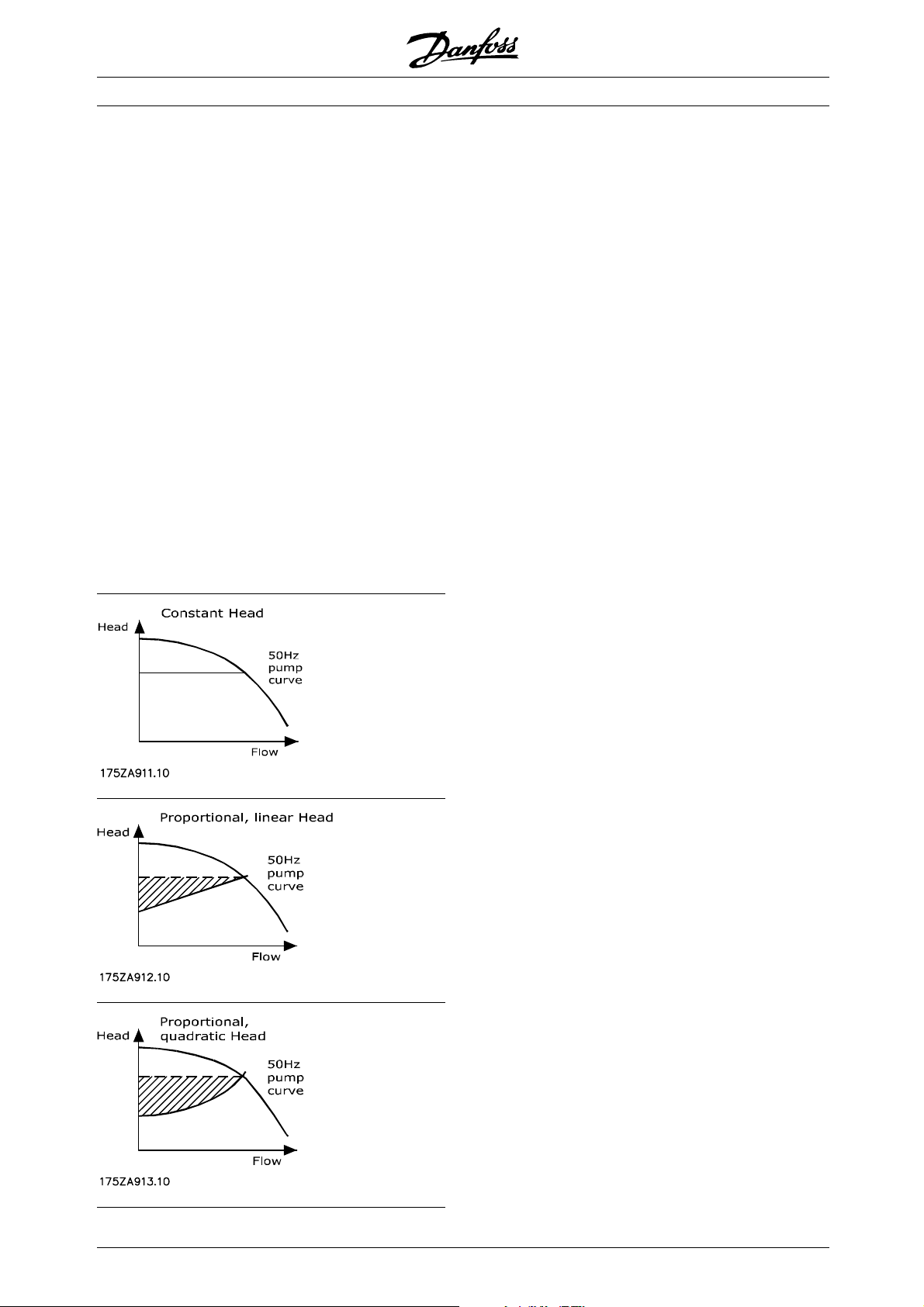
Sensorless contains three different ways of
controlling the pressure where the choice depends
onthetypeofapplication.
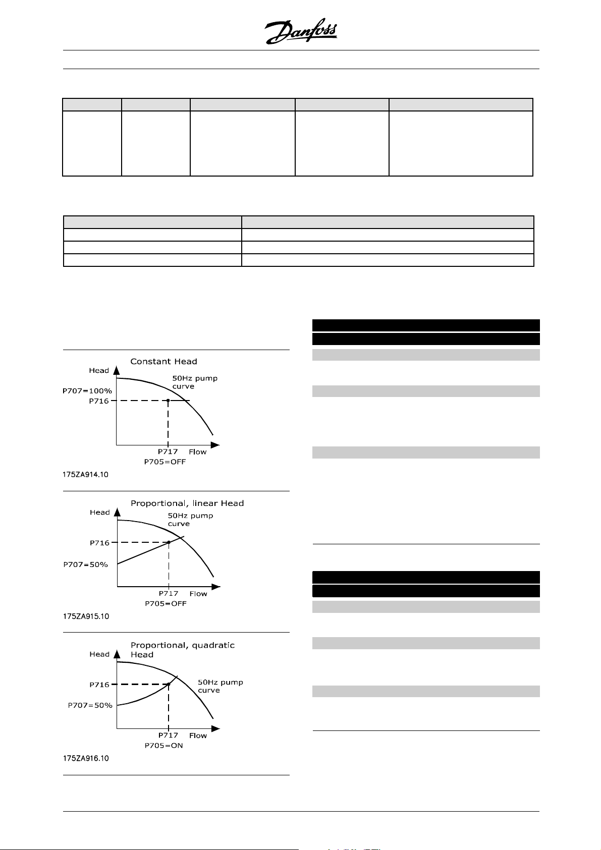
Constant Head: The controller keeps a constant head
across the pump regardless of the flow through the
pump. Does not take pipe friction loss into account.
Proportional linear head: The controller increases the
head across the pump when the flow through the
pump increases, and it decreases the head when the
flow decreases. Takes pipe friction loss into account,
with a linear approximation to the real system curve.
Proportional, quadratic Head: Same as Proportional
Head, but with a quadratic Head curve instead of
linear. Takes pipe friction loss into account, with a
quadratic approximation to the real system curve.
In the manual, these three types of pressure control
are referred to as the user-defined head.
Marked area: Energy savings compared to
constant head control.
(P = K x Flow x Head)
2
MG.10.T1.02 - VLT is a registered Danfoss trademark
Page 3
Sensorless Pump Control for VLT®6000 HVAC / FCM 300
■How Does It Work?
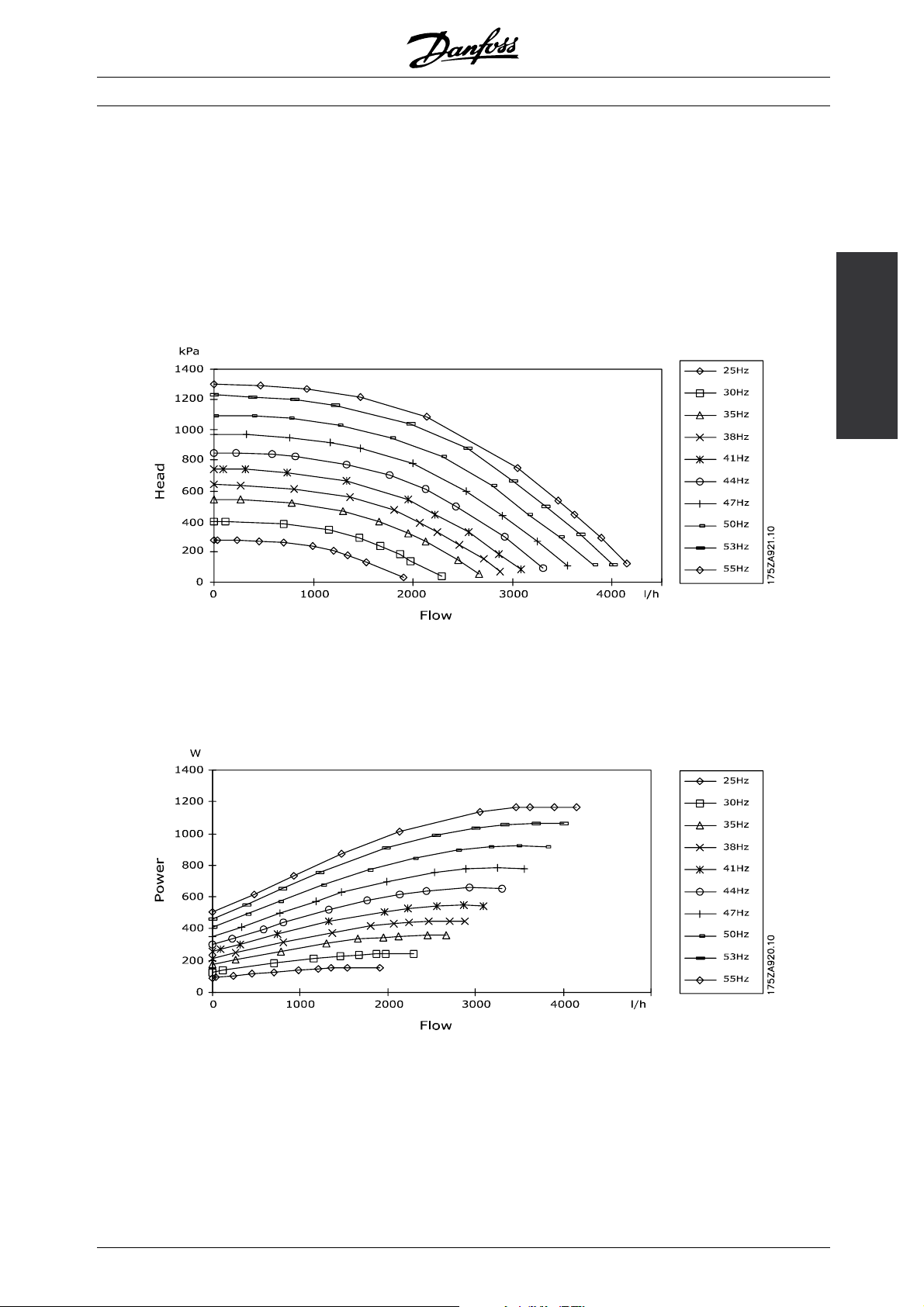
Sensorless is based on the relations between frequency, flow, head and power. So consequently the drive
needs the data shown in the graphs below as input for the calculations. The data are pump specific and need
to be found by measurement. Alternatively, the data can be found by data sheet from the pump supplier if
accurate enough.
The graph below shows a n example of some measured values for flow/head on a typical centrifugal pump.
Head/flow (H/Q) Curves on a 1.5 kW pump
Functionality
The graph below shows the measured values for flow/power.
Power/flow (P/Q) Curves on a 1.5 kW pump
MG.10.T1.02 - VLT is a registered Danfoss trademark
3
Page 4
Sensorless Pump Control for VLT®6000 HVAC / FCM 300
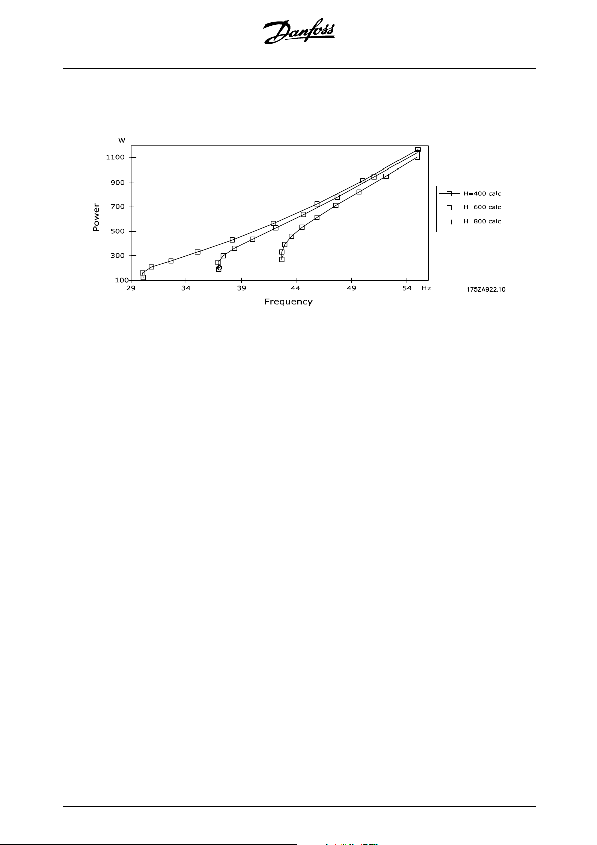
With these values it is possible to create the relation between Power and frequency (P/f curve).
Power/frequency (P/f) Curves on a 1.5 kW pump
With these relations it is now possible to control the pressure (e.g. keeping it constant if that is desired) by
controlling the frequency according to the p ower measurement.
4
MG.10.T1.02 - VLT is a registered Danfoss trademark
Page 5
Sensorless Pump Control for VLT®6000 HVAC / FCM 300
■Limitations
A criteria for Sensorless to work is that there must be a
clear one-to-one relation between head and flow, and
power and flow, (i.e. only one H-value to one Q-value
and opposite) as this forms the basis for the P/f-curve.
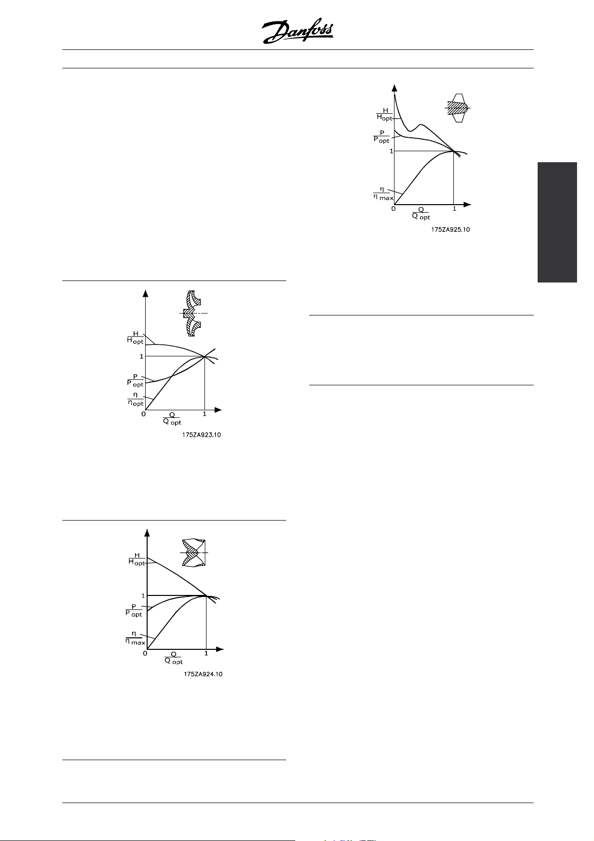
Sensorless can be used with ce ntrifugal pumps
that have radial impeller. On pumps with mixed
flow impellers t here is only limited use as the power
curve is typically flat at high flow rates. A centrifugal
pump with axial impeller cannot be controlled with
sensorless control due to the particular shape of
the head curve. The graphics below show typical
characteristics for the different pump types.
Axial impeller
=200 min
n
q
-1
Not possible
Other limitations: Sensorless control is limited to
non-compressible liquids such as water. Furthermore
the solution is recommended only in closed systems.
Functionality
Radial impeller
=20 min
n
q
-1
Possible
Mixed flow impeller
=80 min
n
q
-1
Limited
MG.10.T1.02 - VLT is a registered Danfoss trademark
5
Page 6
Sensorless Pump Control for VLT®6000 HVAC / FCM 300
This parameter activates the Sensorless control:
Par. No. Par. Name Selection Default Description
Par. 700 (SENSOR-
LESS CONTROL)
The following parameters must be set to make Sensorless work:
VLT 6000 FCM
Par. 100 must be OPEN LOOP Par. 003 must be LOCAL
Par. 101 must be MULTIPLE M OTORS Par. 100 mus t be O PEN LOOP
- Par. 101mustbeVTHIGH
FCM: OFF/ON
VLT 6000:
ENABLE/DISABLE
OFF/DISABLE Set parameter to enable/ON
to activate Sensorless control.
Please observe that this parameter
must be set to disable when doing
measurements.
The following parameters determine the user-defined
head for the system.
■Par. 705 Quadratic Head
Par. 705 Quadratic head
(QUADRATIC HEAD)
Value:
ON/OFF
Function:
Used when selecting the desired type of
Sensorless control: Quadra
tic head or linear
(proportional or constant) head.
Description of choice:
OFF: Generates a linear head/flow reference between
Head Q
(Par. 707) and Head working point (Par. 716).
min
ON: Generates a quadratic head/flow reference
between Head Q
(Par. 707) and Head
min
working point (Par. 716)
■Par. 707 Head Qmin
Par. 707 Head Q
min
(HEAD QMIN)
Value:
0-100%
✭ OFF
✭ 100%
Function:
Sets the head reference at zero flow as a percentage
of the value specified in Par. 716.
Description of choice:
Set a value between
6
MG.10.T1.02 - VLT is a registered Danfoss trademark
0 and 100%.
Page 7
Sensorless Pump Control for VLT®6000 HVAC / FCM 300
■Par. 716 Head Working Point
Par. 716 Head Working Point
(HEAD WORK. POINT)
Value:
FCM
0-2000 kPa
VLT 6000
0-20000 kPa
Function:
Defines the head at the working point.
✭ 10 kPa
✭ 10 kPa
Description of choice:
Set the value in kPa according to the desired head
working point parameter 717. Note the difference
in range for FCM and VLT 6000.
■Par. 717 Flow Working Point
Par. 717 Flow Working Point
(FLOW WORK. POINT)
Value:
0-999 l/s
Function:
Defines the flow at the working point.
Description of choice:
Set the value in l/s according to the desired flow
working point parameter 716.
Functionality
✭ 1l/s
MG.10.T1.02 - VLT is a registered Danfoss trademark
7
Page 8

Sensorless Pump Control for VLT®6000 HVAC / FCM 300
■Control Principle
The control principle builds on converting an internal feedback of inverter pa rameters into a power reference
that the controller uses to adjust the output frequency. The control scheme is illustrated below.
The control part is divided into two parts:
•The Integration control part sums up the actual power error
as the value
decreased w ith the value x
Power error (par. 701)
Integral Power (par. 703)
Delta freq. (par. 702)
is exceeded, the actual speed is increased resp.
and whenever the threshold defined
Integral freq. (par. 704)
•The Three point contro l part uses par. 701 to define the threshold. If the deviation to the actual
power setpoint exceeds the value in par. 701, the
speed increases respectively decreases with
the value in par. 702.
For VLT 6000 the updating takes place every 160ms and for FCM every 20ms.
8
MG.10.T1.02 - VLT is a registered Danfoss trademark
Page 9

Sensorless Pump Control for VLT®6000 HVAC / FCM 300
Control
Principle
MG.10.T1.02 - VLT is a registered Danfoss trademark
9
Page 10

Sensorless Pump Control for VLT®6000 HVAC / FCM 300
■Parameter Setting - Control
The following parameters are use d for setting
up the control:
■Par. 701 Power Error
Par. 701 Power Error
(POWER ERROR)
Value:
FCM: 1-50W
VLT 6000: 1-250W
Function:
See description under "Control Principle".
Description of choice:
A sm all value leads to a lower threshold for the
integration part o f the controller, and thereby faster
reaction. Larger pumps will require a larger value.
■Par. 702 Delta Frequency
Par. 702 Delta Frequency
(DELTA FREQUENCY)
Value:
0,1-1 Hz
✭ 20W
✭ 20W
✭ 0,4 Hz
■Par. 704 Integral Frequency
Par. 704 Integral Frequency
(INTEGRAL FREQUENCY)
Value:
1-100
Function:
See description under "Control Principle".
Description of choice:
A small value leads to a larger frequency step
in the three-point control part. This means
faster but rougher control.
✭ 20
Function:
See description under "Control Principle".
Description of choice:
A small value leads to a smaller frequency step
in the integration control part. This means slower
but more precise control.
■Par. 703 Integral Power
Par. 703 Integral Power
(INTEGRAL POWER)
Value:
1-100
Function:
See description under "Control Principle".
Description of choice:
A small value leads to a higher threshold
for the in tegration part of the controller, and
thereby faster reaction.
✭ 20
10
MG.10.T1.02 - VLT is a registered Danfoss trademark
Page 11

Sensorless Pump Control for VLT®6000 HVAC / FCM 300
■Power Compensation
Par. 708 Power Compensation
(POWER C OMP)
Value:
VLT 6000: -1000W-1000W
FCM: -100W-100W
Function:
To obtain a more precise control and read-out, it can be
an advantage to correct the total power in the P/f table
by an offset, positive or n egative. Example on effect:
On a 1½ kW pump, about -30W can change the flow
read-out from 2.2 l/s to 1.8l/s. at m ax flow of 10 l/s.
Description of choice:
When preparing the system for sensorless control,
compare the calculated flow values with real measured
values. If there is a deviation in figures, this can
be caused by an offset in values. Enter the value
necessary to obtain as small a deviation as possible.
✭ 0
✭ 0
Functionalities
Programming other
MG.10.T1.02 - VLT is a registered Danfoss trademark
11
Page 12

Sensorless Pump Control for VLT®6000 HVAC / FCM 300
■Analog Output
Terminal 45 on the VLT 6000 and terminal 9 on the
FCM can be used to read out either flow or head.
VLT 6000:
Par. 321 Terminal 45, output
FCM:
Par. 304 Terminal 9, output
Value
The following choices ha ve been added :
Choice Choice no. FCM Choice no. VLT 6000
SENS. FLOW = 0-20 mA [22] [44]
SENS. FLOW = 4-20 mA [23] [45]
SENS. HEAD = 0-20 mA [24] [46]
SENS. HEAD = 4-20 mA [25] [47]
■Par. 720 AO Max Value
Par. 720 AO Max Value
(AO MAX VALUE)
Value:
1-9999
✭ 1
Function:
This parameter is used to convert the current
signal to a head or flow value.
Description of choice:
Enterthemaximumvalueforheadorflow,atwhich
the analog output must give 20 mA.
Example:
Par. 321 is SENS. HEAD = 4-20 mA
Par. 720 is 200 (kPa)
The actual head is 100kPa. That brings
terminal 45 up to 12mA.
12
MG.10.T1.02 - VLT is a registered Danfoss trademark
Page 13

Sensorless Pump Control for VLT®6000 HVAC / FCM 300
■Analog Input
It is possible to reduce the user-defined head
with the following parameters.
Drive Input Parameter Choice Value
FCM DI 9 332 [38] SENSORLESS
VLT 6000 AI 53 308 [10] SENSORLESS HEAD
Function: The ana
the user-defined head Q with a desired percentage.
Using a 0-10 V potentiometer means that 0 V equals
0% and 1 0 V e
is desired, set the potentiometer to 2.5 V.
log input can be used to reduce
quals 100%. So if a 25% reduction
Functionalities
Programming other
MG.10.T1.02 - VLT is a registered Danfoss trademark
13
Page 14

Sensorless Pump Control for VLT®6000 HVAC / FCM 300
■Read-outs in LCP
In display line 1.1, 1.2 and 1.3 it is possible
to read out the following:
Sensorless Head (very useful, if the user-defined
Head is proportional)
Sensorless Flow
Sensorless Power, which is the actual power
consumption of the system. It is recommended to use
this read-out when measuring the pump characteristics.
The value is filtered to make it more stable (Filter time
constant FCM: 500 ms and V LT 6000: 4000 ms).
These choices can be programmed into the following parameters:
Functionality Par. no. FCM Par. no. VLT 6000
Large d isplay read-out/Display line 2 009 007
Display line 1.1 010 008
Display line 1.2 011 009
Display line 1.3 012 010
The read-outs have the following numbers:
Choice Choice no. FCM Choice no. VLT 6000
Sensorless Power [33] [33]
Sensorless Flow [34] [34]
Sensorless Head [35] [35]
14
MG.10.T1.02 - VLT is a registered Danfoss trademark
Page 15

Sensorless Pump Control for VLT®6000 HVAC / FCM 300
■Power/Frequency Read-out
To enable the user to check if the calculated points
used for control look right, Parameter 799 (PF
READOUT) has been created. The parameter is
indexed as read-only and contains 20 values: 10
points holding P ower/frequency values. The values
should develop like shown in the g rap h below:
All odd numbers show the power, and the even numbers
show the frequencies. It is important for the control that:
[1] < [3] < [5] < [7] < [9] < [11] < [13] <
[15] < [17] < [19] and
[2] < [4] < [6] < [8] < [10] < [12] < [14] < [16] < [18] < [20].
Functionalities
Programming other
MG.10.T1.02 - VLT is a registered Danfoss trademark
15
Page 16

Sensorless Pump Control for VLT®6000 HVAC / FCM 300
■VLT 6000
Please note that the choice in pa rameter 300 "selection
of MSB" has been removed, and consequently
only 2 setups are available.
16
MG.10.T1.02 - VLT is a registered Danfoss trademark
Page 17

Sensorless Pump Control for VLT®6000 HVAC / FCM 300
■Measuring Values
■Introduction
This instruction concerns the use of SControl for Sensorless Pump Control for VLT 60 00 and FCM 30 0. Please
contact Danfoss to acquire th e SControl Software.
■Installation and Setup of the Software
SControl operates in two modes:
•Productionmode
This mode is used in production in cases where pump data are not supposed to be changed. A pump can
be chosen and data can be downloaded to the drive.
•Editmode
This mode is used when entering different pump data, adding and removing pumps. Also in this mode,
data can be downloaded to the drive.
Please note that only the command buttons show which mode is active.
■Installation
Run the "Setup.exe" file and the program will be installed. Only the Production Mode is installed in the first
step. In order to install the Edit mode, create a short-cut of the program and type " edit" at the end of the
path: "C:\Program F iles\Dan fo ss Drives\SControl\Scontrol.exe" edit Remember to include a space before
edit; otherwise it will not work.
Values
Measuring
MG.10.T1.02 - VLT is a registered Danfoss trademark
17
Page 18

Sensorless Pump Control for VLT®6000 HVAC / FCM 300
■Entering Pump Data
To add a pump: Push the command button +
To remove a pump: Push the command button -
If the pump is connected to a VLT 6000, write VLT6*** in the p um p type followed by the pump type.
For entering data, choose Database Editor.
Enter frequencies (one or more) in the left column. Start with the highest value. More frequencies can be
added later.
18
MG.10.T1.02 - VLT is a registered Danfoss trademark
Page 19

Sensorless Pump Control for VLT®6000 HVAC / FCM 300
Select one frequency and add flow/power/head values for that s
important to have the same order as this:
pecific frequency. Start with no flow. It is
Values
Measuring
MG.10.T1.02 - VLT is a registered Danfoss trademark
19
Page 20

Sensorless Pump Control for VLT®6000 HVAC / FCM 300
■Number of Measurements
The specified accuracy of Sensorless Pump Control (maximum 5% deviation) is based on having 100
measurements (10 frequencies and 10 flow/power and head measurements for each frequency). The minimum
number is 16 measurements (flow/power/head values) for at least 4 frequencies.
The program also has a func tion ality called "Auto Insert Data". It is only necessary to use t his functionality with
10 measurements for 1 frequency, and the program will calculate the remaining points.
Please note that using less tha n 100 measurements will decrease the accurac y. Therefore check the accuracy
after programming and make sure tha t it is within an acceptable level.
Step by step
1. Put the drive at fixed speed.
2. Find max flow (do not write it into SControl)
3. Measure Power/Head at 0 flow, write data in SControl.
4. Spread the flow measurements evenly in 10 steps, from 0 to max flow, and enter Power/Head/Flow
values in to SControl (see example above) .
5. Do the measurements for 10 frequency steps evenly spread between Fmax and Fmin (unles s using
less than 100 measurements as described above).
■Other Functionalities of the Program
Pressing the "VLT paramete
rs" command button, you can enter desired values for parameters. When
downloading data to the drive, the listed parameters will be changed according to the entered values. The
default setting of these parameters can be changed in "Setup" and "Default VLT Parameter Setting".
NOTE:TheparametersinFCMandVLT6000HVACaredifferent,soitisnotpossibletomakeagenerallist.
Pressing the "Download Da ta" and "Start" button will start downlo ad ing of pump data and parameter settings
into the drive.
20
MG.10.T1.02 - VLT is a registered Danfoss trademark
Page 21

Sensorless Pump Control for VLT®6000 HVAC / FCM 300
■Data and Read-outs
The information on the left (P_A, P_B…) is in fact the coefficients to HEAD/FLOW and POWER/FLOW curves:
3
H=f(Q)=aQ
P=f(Q)=aQ
+bQ2+cQ+d
2
+bQ+c
The feature "DB plotter" in "Actions" can give a graphical overview of data measured at one frequency at a time:
This graph displays th ese data:
MG.10.T1.02 - VLT is a registered Danfoss trademark
21
Values
Measuring
Page 22

Sensorless Pump Control for VLT®6000 HVAC / FCM 300
If more data have bee n entered for other frequencies, simp ly sele
the plotter window.
Use "Export to Excel" to copy all data to the Excel sheet that comes with the installa tion of Scontrol: Open the
Excel sheet "Sensorless Plot" and place the marker at cell A1, a nd choose "Edit" and "Paste".
ct the other frequency witho ut closing
22
MG.10.T1.02 - VLT is a registered Danfoss trademark
 Loading...