

Page 1
Data sheet
Gasketed Plate Heat Exchangers (DN 300 / 12”)
S81 / S121 / S188 / S251
Description
SONDEX® gasketed plate heat exchangers are
the ideal choice for a wide range of applications
across numerous market segments.
We have the largest plate portfolio in the
world, and we customize each heat exchanger
to meet your exact requirements. Innovative
technologies and smart design make our
gasketed plate heat exchangers a stellar
investment.
Benefits:
• Individually customized solution that
perfectly matches your requirements and
lowers your energy consumption.
• High performance and a low pressure
drop eliminate unnecessary burdens on
your system and optimize overall system
performance.
• The design results in a compact solution with
a small footprint, simple installation, and easy
access for maintenance.
Common applications:
• HVAC industry
• Marine/offshore industry
• Dairy/food/beverage industry
• Sugar industry
• Biogas industry
• Pulp and paper industry
• Heavy industry
• Mining industry
• Petrochemical industry
• Chemical industry
Main data:
• Min. temperature −10 °C
• Max. temperature 180 °C
• Max. working pressure 16 / 25 bar (10 bar on
request)
• Water and different fluids, steam
• Connection size DN 300 or 12”
Approvals:
• Please contact your local Danfoss/SONDEX®
sales representative for an overview of the
available approvals in your region
Construction standard:
• EN13445 (PED 2014/68/EU)
• ASME sec VIII, Div. 1
| 2019.07 VD.JQ.R1.02 | 1
Page 2

Data sheet S81 / S121 / S188 / S251 (DN 300)
Naming of units
S81-IS16-21-TKTL89
3)
1)
1)
Type of heat exchanger:
TKTL89 - Plate grouping
21 - Number of plates in the heat exchanger
16 - Design pressure of the heat exchanger
IS - Frame type
2)
81 – Type of heat exchanger
S – Gasketed heat exchanger
81 - …
Letter S81 shows type of the attachment of gasket to plate:
e.g. 81 (without A) – SonderLock
81A (with A) – Hang-on
2)
Description of frame types:
There are few different frame types which can be offered for different applications and duties.
IS – with suspension roller,
IG – without suspension roller,
FS – food/sanitary with suspension roller,
FG - food/sanitary,
ST – simple design of frame with threaded connections
3)
Channel grouping:
In this example, the heat exchanger combines TK and TL channels. The share of TL channels equals
89% of the total number of channels.
The number of channels is defined as “the number of plates - 1”.
TK - short thermal length
TM - medium thermal length
TL - long thermal length
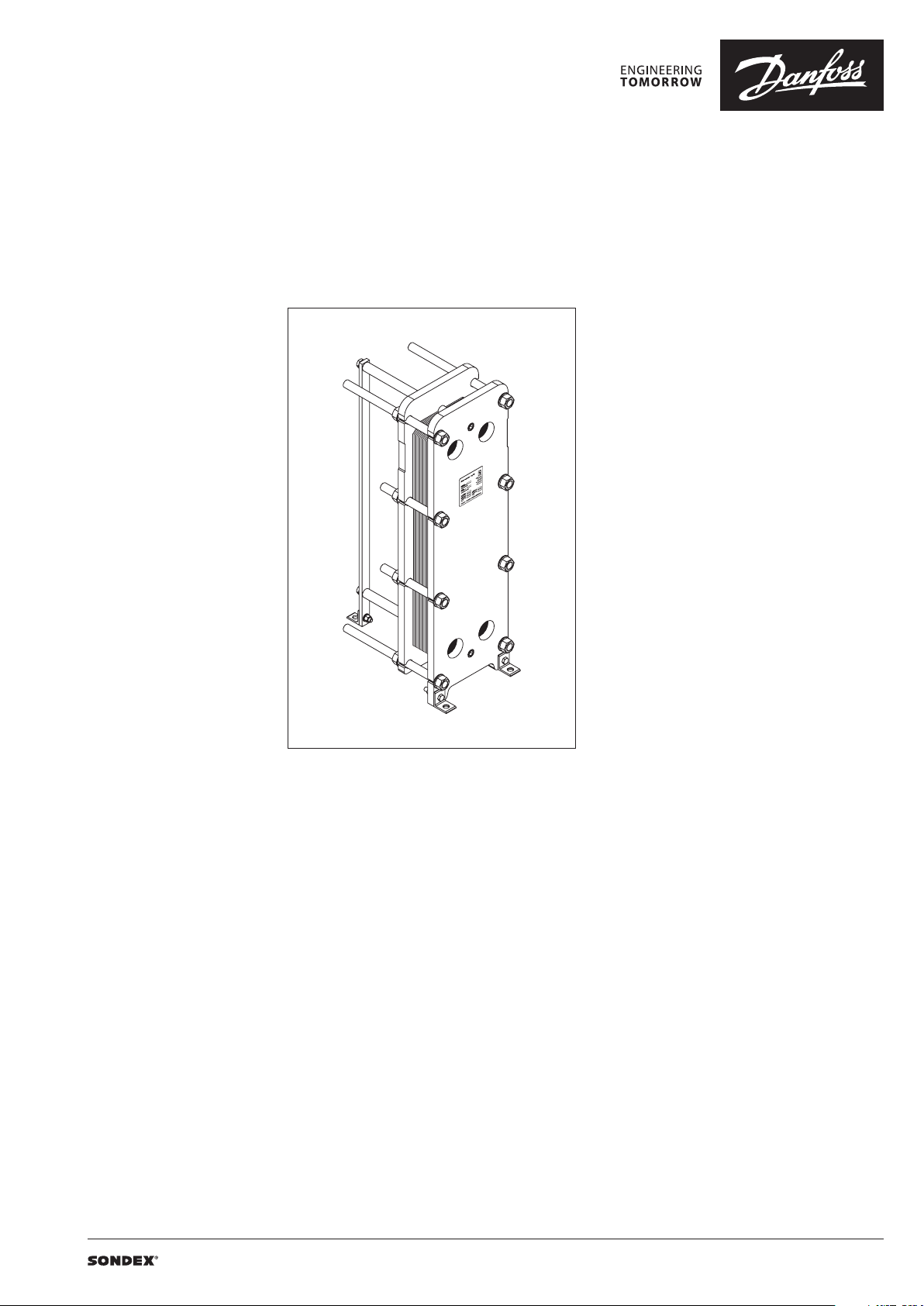
Heat exchanger design
Gasketed heat exchangers consist of
Carrying Bar
Plate Pack
Plate
Connections
Head
Flange Connections
Foundation Feet
Column
Follower
Tie Bolt
Guiding Bar
Anatomy of a SONDEX® plate heat exchanger - IS frame.
2 | VD.JQ.R1.02 | 2019.07
Page 3
Data sheet S81 / S121 / S188 / S251 (DN 300)
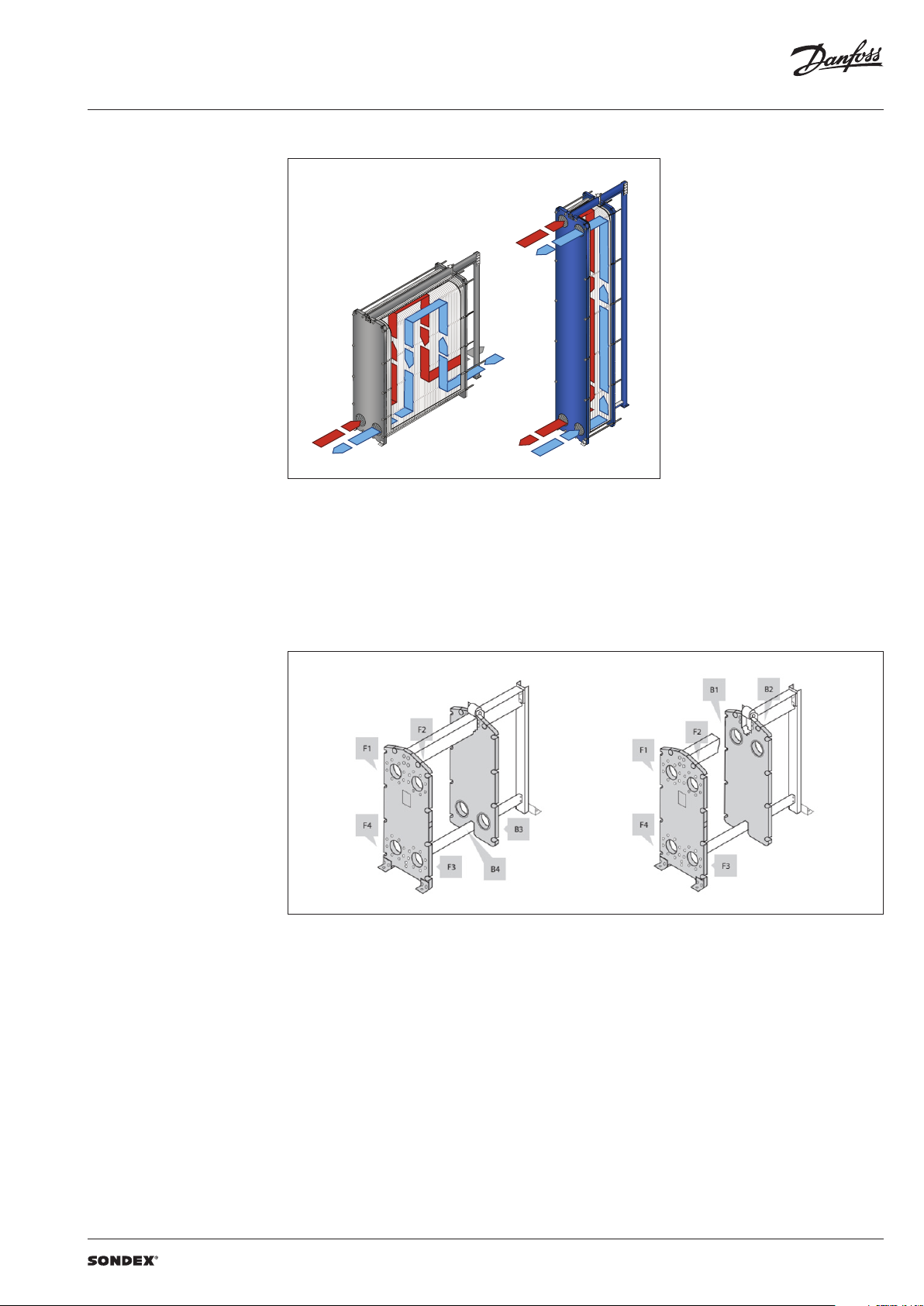
To the left: A multi-pass solution with connections
Heat exchanger design
(continued)
Multi-pass design
on the follower and the head.
To the right: A single-pass solution with
all connections on the head.
Connections
The heat exchanger may have connections on
both front and back-end sides of the unit.
Connections on the front-end plate are marked
with F and connections on the back-end plate
are marked with B. The numbers 1, 2, 3 and 4
designate the position of the connection on the
end-plate from the top-left port clockwise.
VD.JQ.R1.02 | 3 | 2019.07
Page 4

Data sheet S81 / S121 / S188 / S251 (DN 300)
SONDEX®
plate
range
Common
Technical data Heat exchanger S67 / S113 / S155
Typ e S81 S121 S188 S251
Max. working pressure
Max. operating temperature
Min. operating temperature -10
Flow medium Water and different fluids, steam
Volume / channel l 3.1 4.7 7.3 9. 8
Connection size DN 300 / 12”
Connection type
Plate material
Plate thickness mm
Gasket material
Gasket attachment t ype Sonder Lock
Liners in connections
Frame
Frame painting specification Painting available for corrosion categories C2L, C4M, C5M
1)
Not available f or all frame variations
2)
SonderSaf e - double plate
PN
(bar)
°C
• DN 300/12” flanges. Carbon steel, rubberlined or cladded with AISI 316L
(other materials available on request)
Stainless steel EN 1.440 4 (AISI 316L), EN 1.4301 (AISI 304), SMO254, Hastelloy C276,
titanium Gr.1
Other materials available on request
0.4; 0.5; 0.6; 0.7
2 x 0.4 SonderSafe plates
Other thicknesses available on request
NBR, EPDM,
Other materials available on request
• Rubber NBR, EPDM,
• Stainless steel EN 1.440 4 (AISI 316L), EN 1.4301 (AISI 304), SMO254, Hastelloy C276,
titanium Gr.1
• Painted frame, color RAL 5010 (other colors available on request)
• Stainless steel frame, designed for the sanitary applications (e.g. food and dairy
industries)
(10)1), 16, 25
Up to 180
1)
2)
Using the right plate for each individual duty
is very important, as it greatly impacts the
efficiency of the entire installation.
It is important that the length of the plates and
the type of pattern match the requirements of
individual thermal duty.
We have developed a wide plate portfolio to
provide the perfect plate and connection size for
any duty.
No application is too small or too big for us - we
provide the optimal technical solution every
time.
Our extensive SONDEX® plate portfolio
includes plates that lie outside the commonly
manufactured plate sizes to cover all thermal
duties optimally.
plate
range
4 | VD.JQ.R1.02 | 2019.07
Page 5

Data sheet S81 / S121 / S188 / S251 (DN 300)
Accessories Insulation
Recommended applications:
The insulation jacket for the plate heat exchanger
is used in different applications with high
temperatures and cooling systems.
Application Heating Cooling
Material
Outer cap
Internal insulation 0.05 mm aluminium foil
Panel fixation Plastic rivets
Temperature 20 … 200 °C -50 … -80 °C
U-value 0.55 W/m2K 0.3 8 W/m2K
Insulation class 3
Heat loss 17.1 W/m
Please note:
Inlet and outl et temperatures in the exch anger have been based on 9 0/50 – 30/70 °C.
1)
The loss of he ating/cooling is stated per m2 surface on the insu lation jacket.
The bottom o f the heat exchanger is not insu lated and this fact has been e xcluded.
A possible loss of ve ntilation, largely dep endent on the mounting of the h eat exchanger, has not been take n into account either.
Drip trays
Recommended applications:
The drip tray is available in two types. A “failsafe” solution which prevents water or liquid
from leaking onto the floor, or when the
heat exchanger is dismantled, or opened for
inspection and maintenance. And an insulated
drip tray for cooling applications, which
collects condensate formed outside of the plate
heat exchanger.
45 mm mineral wool
Not flammable
DIN EN 4102A2
40 mm PU-foam
DIN 4102-1 B2
1 mm aluminium
“Stucco” Embossed
1)
2
1)
4
-
Materials
Drip tray consists of:
• 1 mm galvanized steel frame
• Hanging brackets in galvanized steel
• 60 mm Polyurethane insulation for cooling
applications
• Draining valve.
Spare parts
Spare parts for gasketed heat exchangers, such
as plates, gaskets, frame parts can be ordered for
maintenance, repair, increasing heat exchanger
capacity, etc.
Selection and ordering Please contact your local SONDEX® or Danfoss
sales representative for the selection and / or
ordering of the heat exchangers, spare parts, and
accessories.
Please contact your local Danfoss or SONDEX®
sales representative to provide you with
information on spare parts available for gasketed
heat exchangers.
For contact information please visit
https://www.danfoss.com/en/contact-us.
VD.JQ.R1.02 | 5 | 2019.07
Page 6

Data sheet S81 / S121 / S188 / S251 (DN 300)
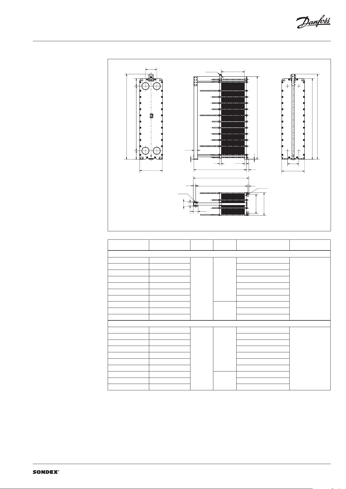
Dimensions
Non-sanitary applications
Any connection can be used for primary side in.
All the rest are made correspondingly.
S81 frames
Ø100 L1
323
F1
F2
7
H
1080
F4
F3
363
480
W
1806
7
50
20
Ø18
140
75
L
L + 150
L+ 80
323
B1
B2
H
1806
B3
7
14
80
100
50
Ø25
W
820
480
W
1080
B4
363
Drawing of S81 IS16 frame
Number of plates
L (frame length)
1)
(mm)
W
(mm)
H
(mm)
Weight max, empt y
(kg)
2)
Connection type
S81 I S16
7 29 687
30 95 1087 2498
96 145 1387 2806
146 179 1587 3024
180 262 2087 3546
263 348 2740
970
38.19”
349 431 3240 5109
432 598 4240 6240
599 765 5240
766 931 624 0 8497
190 6
(75.0 4”)
1956
(7 7.01“ )
2208
(86.93“)
2108
DN 300 flange or 12”
4546
7370
S81 IS 25
7 31 697
32 96 1097 2939
97 − 145 1397 3323
146 178 1597 3581
179 260 2097 4222
261 342 2 740
1030
(40. 55”)
343 424 3240 5504
425 588 4240 6786
589 752 5240
753 916 6240 9 351
1)
the indicate d maximum number of pla tes is based on the minimum plate thi ckness allowable for the PN le vel of the unit;
2)
the maximum w eight of the empty unit with t he maximum allowable nu mber of plates;
*)
PN class 6 bar / 10 bar is a vailable on request.
190 6
(75.0 4”)
1956
(7 7.01“ )
2208
(86.93“)
2430
DN 300 flange or 12”
4863
8068
flange
flange
6 | VD.JQ.R1.02 | 2019.07
Page 7

Data sheet S81 / S121 / S188 / S251 (DN 300)
Dimensions (continued)
Non-sanitary applications
S121 frames
H
Ø100
F1
F2
1490 323363
F3
F4
150
L1
B1B2
2265
2176
B3 B4
14
480
W
20
75
L
80
100
W
L + 125
100
L - 25
50
Ø25
Ø25
200
160
W
820
200
Drawing of S121 IS16 frame
Number of plates
L (frame length)
1)
(mm)
W
(mm)
H
(mm)
Weight max, empt y
(kg)
2)
Connection type
S121 IS16
7 - 29 830
2713
30 - 95 123 0 3229
96 - 145 1530 3634
146 - 179 17 30 3929
180 - 262 2230 4585
263 - 345 2730 5273
970
38.19”
2366
(93 .15”)
DN 300 flange or 12”
346 - 429 3230 6037
430 - 595 423 0
596 - 762 5230 8 911
763 - 929 6230 10332
2618
(103. 07“)
7433
S121 I S25
7 - 26 850
4171
27 - 91 125 0 4820
92 - 140 1550 5309
141 - 173 17 50 5637
174 - 255 2250 6 456
256 - 337 2750 7273
1030
(40. 55”)
2366
93 .15”
DN 300 flange or 12”
338 - 419 3250 8091
420 - 583 425 0
584 - 747 5260 113 62
748 - 911 6260 129 97
1)
the indicate d maximum number of pla tes is based on the minimum plate thi ckness allowable for the PN le vel of the unit;
2)
the maximum w eight of the empty unit with t he maximum allowable nu mber of plates;
*)
PN class 6 bar / 10 bar is a vailable on request.
2618
(103. 07“)
9726
flange
flange
VD.JQ.R1.02 | 7 | 2019.07
Page 8

Data sheet S81 / S121 / S188 / S251 (DN 300)
Dimensions (continued)
Non-sanitary applications
S188 frames
2806
480
L1
Ø 100
323
F1
F2
H
2120
F4
F3
2895
150
363
20
75
14
80
B1B2
H
B4
B3
L 100
W
L + 125
100
L - 25
50
Ø25
Ø25
200
160
200
W
820
Drawing of S188 IS16 frame
Number of plates
L (frame length)
1)
(mm)
W
(mm)
H
(mm)
Weight max, empt y
(kg)
2)
Connection type
S188 I S16
7 - 29 830
3553
30 - 95 123 0 4226
96 - 145 1530 4752
146 - 179 17 30 5132
180 - 262 2230 5988
263 - 345 2730 6878
970
38.19”
2996
(117. 95” )
DN 300 flange or 12”
346 - 429 3230 7848
430 - 595 423 0
596 - 762 5230 11554
763 - 929 6230 134 63
3248
(12 7.87“ )
9652
S188 I S25
7 - 26 850
4540
27 - 91 125 0 5323
92 - 140 1550 5958
141 - 173 17 50 6 412
174 - 255 2250 7435
256 - 337 2750 8590
1030
(40. 55”)
2996
(117. 95” )
DN 300 flange or 12”
338 - 419 3250 9693
420 - 583 425 0
584 - 747 5250 14230
748 - 911 6250 16437
1)
the indicate d maximum number of pla tes is based on the minimum plate thi ckness allowable for the PN le vel of the unit;
2)
the maximum w eight of the empty unit with t he maximum allowable nu mber of plates;
*)
PN class 10 bar is avail able on request.
3248
(12 7.87“ )
118 96
flange
flange
8 | VD.JQ.R1.02 | 2019.07
Page 9
Data sheet S81 / S121 / S188 / S251 (DN 300)
Dimensions (continued)
Non-sanitary applications
S251 frames
H
323
2750
363
480
F1 F2
F4
W
Ø100
F3
150
20
75
L1
B2
B1
3525
B3 B4
H
3436
14
80
L
100
480
W
L + 125
100
L - 25
50
Ø25
Ø25
200
200
160
W
820
Drawing of S251 IS16 frame
Number of plates
L (frame length)
1)
(mm)
W
(mm)
H
(mm)
Weight max, empt y
(kg)
2)
Connection type
S251 IS16
7 - 29 830
4393
30 - 95 123 0 5222
96 - 145 1530 5869
146 - 179 17 30 6332
180 - 262 2230 7386
263 - 345 2730 8479
970
38.19”
3626
(142. 76”)
DN 300 flange or 12”
346 - 429 3230 9666
430 - 595 423 0
596 - 762 5230 14249
763 - 929 6230 164 85
3878
(152.68“)
118 61
S251 IS25
7 - 26 850
5603
27 - 91 125 0 6 541
92 - 140 1550 7353
141 - 173 17 50 7910
174 - 255 2250 917 3
256 - 337 2750 10578
1030
(40. 55”)
3626
(142. 76”)
DN 300 flange or 12”
338 - 419 3250 11932
420 - 583 425 0
584 - 747 5250 1708 6
748 - 911 6250 19623
1)
the indicate d maximum number of pla tes is based on the minimum plate thi ckness allowable for the PN le vel of the unit;
2)
the maximum w eight of the empty unit with t he maximum allowable nu mber of plates;
*)
PN class 10 bar is avail able on request.
3878
(152.68“)
144 83
flange
flange
VD.JQ.R1.02 | 9 | 2019.07
Page 10

Data sheet S81 / S121 / S188 / S251 (DN 300)
10 | VD.JQ.R1.02 | 2019.07
Page 11

Data sheet S81 / S121 / S188 / S251 (DN 300)
VD.JQ.R1.02 | 11 | 2019.07
Page 12

Data sheet S81 / S121 / S188 / S251 (DN 300)
| DHS-SRMT/SI | 2019.0712 | VD.JQ.R1.02
 Loading...