

Page 1
User Manual
PLUS+1® Compliant
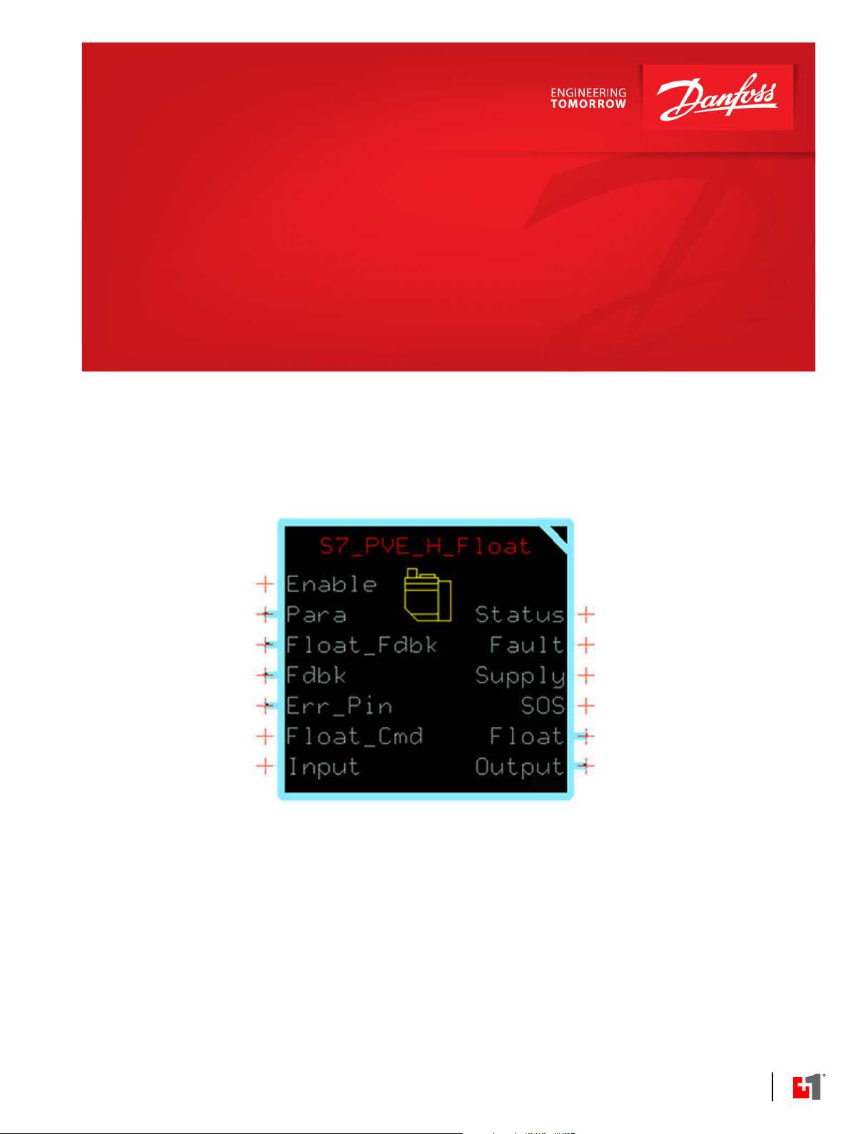
S7 PVE H Float Function Block
www.danfoss.com
Page 2
User Manual
PLUS+1® Compliant S7 PVE H Float Function Block
Revision history Table of revisions
Date Changed Rev
May 2018 Updated threshold graphic 0102
January 2018 First edition 0101
2 | © Danfoss | May 2018 AQ00000241en-000102
Page 3

User Manual
PLUS+1® Compliant S7 PVE H Float Function Block
Contents
S7_PVE_H_Float Function Block
Inputs....................................................................................................................................................................................................4
Function Block Parameter Values...............................................................................................................................................5
Outputs................................................................................................................................................................................................ 5
Function Block Connections.........................................................................................................................................................6
Threshold and Maximum Values................................................................................................................................................ 6
Status and Fault Logic.....................................................................................................................................................................7
Status Logic...................................................................................................................................................................................7
Fault Logic..................................................................................................................................................................................... 8
Power Two or More PVE-Type Valve Actuators from One DigOut................................................................................. 8
MC Controller Configurations......................................................................................................................................................9
Configure the MFIn for the Error_Pin Input.................................................................................................................... 10
Configure the DigAn for the Error_Pin Input..................................................................................................................10
Configure the MFOut for the Supply Output................................................................................................................. 11
Configure the DigOut for the Supply Output.................................................................................................................12
Configure the MFOut for the Block's Output..................................................................................................................13
SC Controller Configurations.....................................................................................................................................................13
How to Configure an MFIn for the Error_Pin Input...................................................................................................... 14
How to Configure a DigAn for the Error_Pin Input...................................................................................................... 15
How to Configure an MFOut for the Supply Output................................................................................................... 16
How to Configure a DigOut for the Supply Output..................................................................................................... 17
How to Configure an MFOut for the Block's Output....................................................................................................18
How to Configure an MFOut for the Float Output....................................................................................................... 19
How to Configure a DigOut for the Float Output......................................................................................................... 20
©
Danfoss | May 2018 AQ00000241en-000102 | 3
Page 4
User Manual
PLUS+1® Compliant S7 PVE H Float Function Block
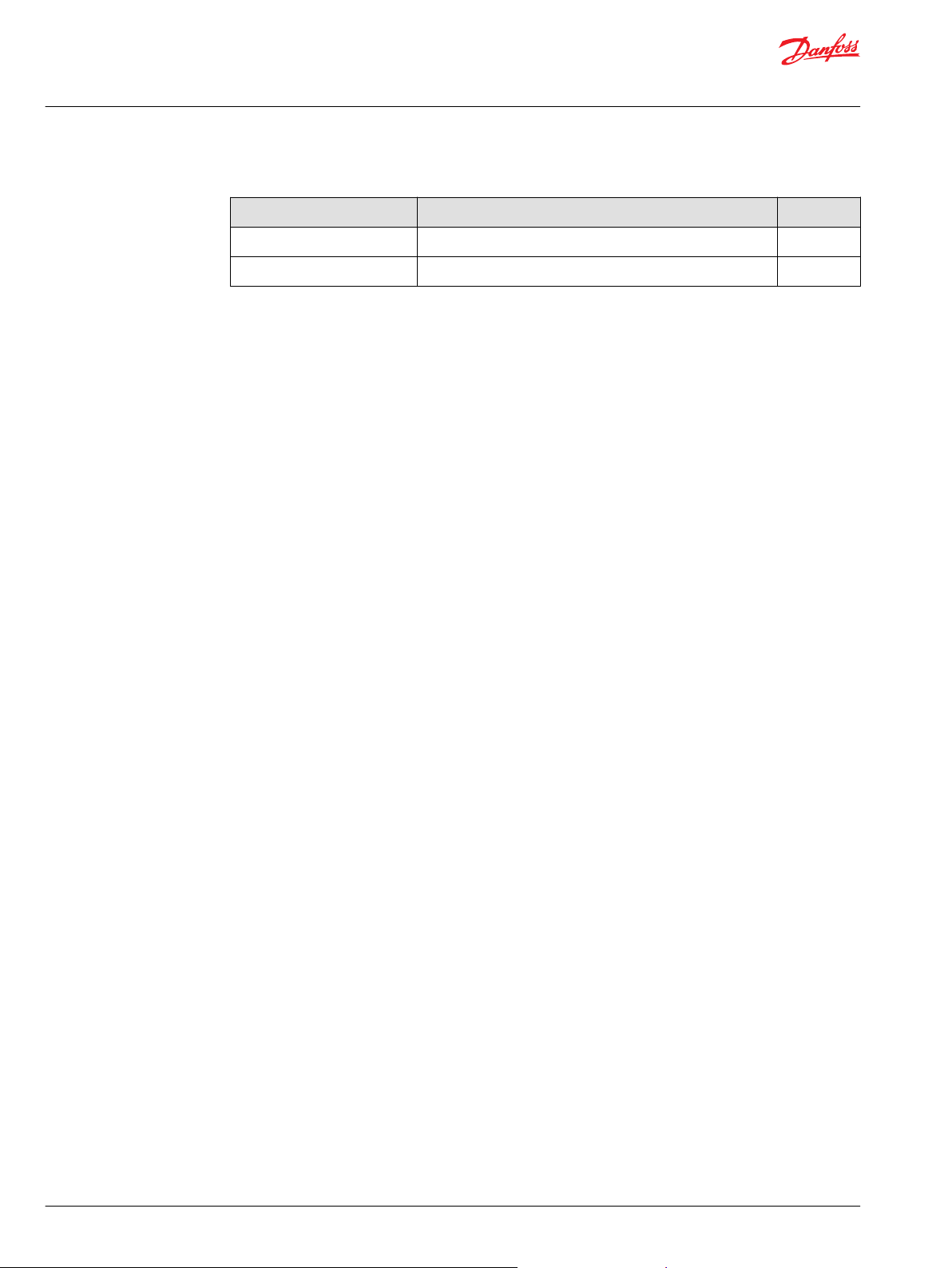
S7_PVE_H_Float Function Block
This function block reports the feedback of Danfoss Series 7 valve actuators for valves configured for a
float option.
You can move the main spool into its float position by powering a dedicated float pin.
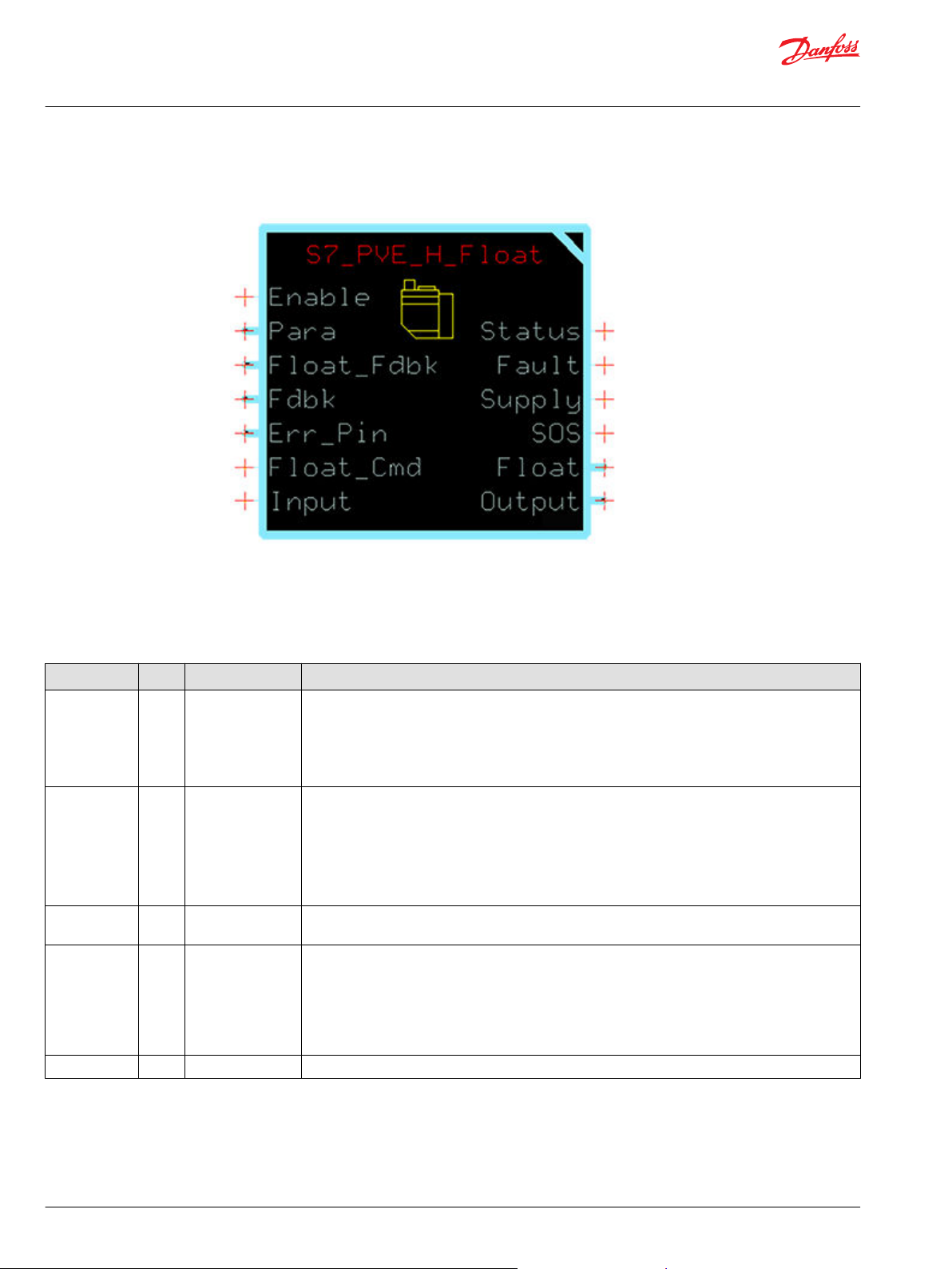
Inputs
Inputs to the function block are described.
Item Type Range Description
Enable BOOL —— Enables and disables the function block.
•
True—Enables the function block's Supply output and releases the block's Output from its neutral
hold (5,000).
•
False— Disables the function block's Supply output and holds the block's Output at neutral (5,000).
•
False—The Output goes to 5,000.
Para Bus
Float_Fdbk Bus —— Reports the pin status of the PVE actuator's Float pin.
Fdbk Bus —— Input for the Status bus from the MFOut that reports the output status of the MFOut that receives the
Error_Pin Bus —— Input for a bus from an MFIn or DigAn with a DigIn signal from the valve actuator's Error_Pin.
Inputs:
Thld_A— Threshold is the hydraulic deadband in the actuator. Applies to the A port.
Thld_B—Threshold is the hydraulic deadband in the actuator. Applies to the B port.
Fault Reaction—T Sets the output constantly in neutral if the Error_Pin goes high.
F Does not change the output in case the Error_Pin goes high.
SuppTimeAtNeut—Supply Time At Neutral: Sets time that the supply stays on after return to neutral. If
-1, then the supply is always on.
The function block uses this input to detect shorts on the PVE actuator's Float output.
function block's Output.
(Each MFOut inside the Inputs page reports, through a Status bus, the state of a corresponding
MFOut inside the Outputs page.)
•
On MC controllers, the Status bus inputs a PinStatus signal.
•
On SC controllers, the Status bus inputs a Status signal.
4 | © Danfoss | May 2018 AQ00000241en-000102
Page 5
User Manual
PLUS+1® Compliant S7 PVE H Float Function Block
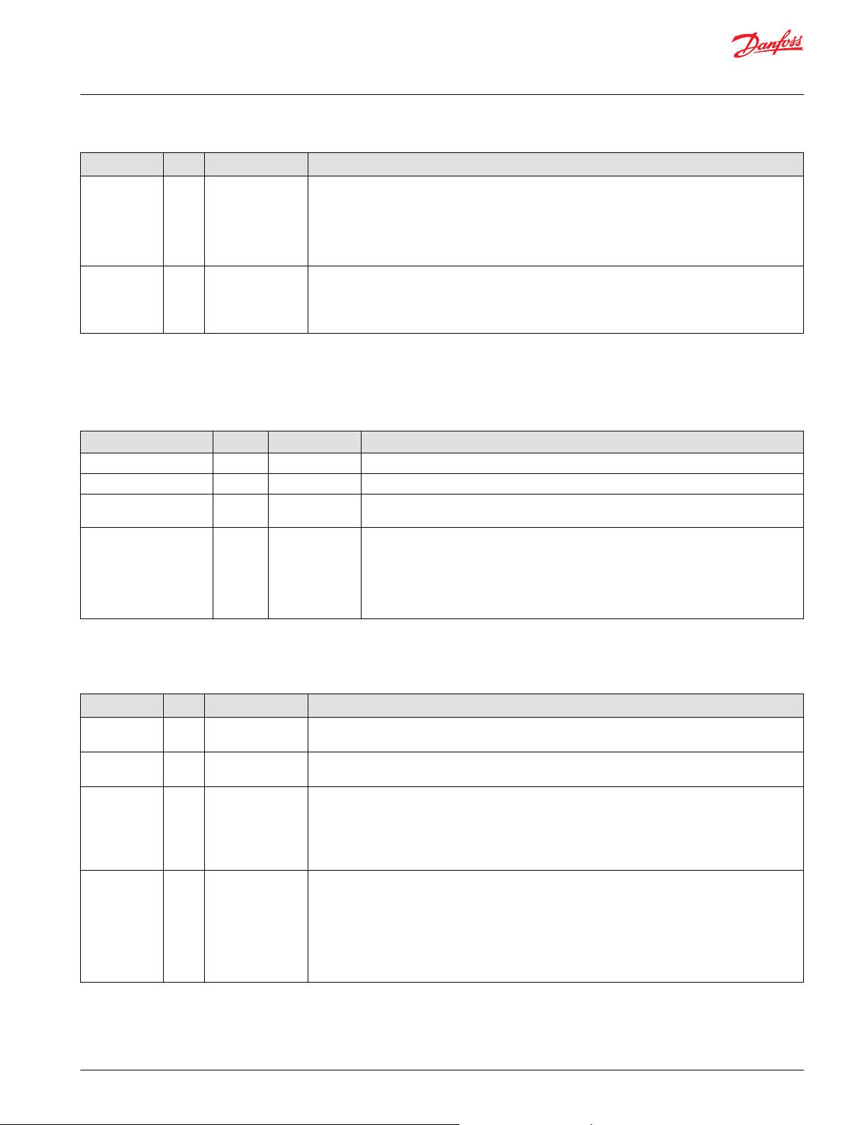
S7_PVE_H_Float Function Block
Item Type Range Description
Float_Cmd BOOL ——
Input S16 ±10,000 Command signal for the actuator spool.
Function Block Parameter Values
The function block's operating characteristics are set by para bus input signals.
The following table describes the Para bus inputs signals.
Input Type Range Description
Thld_A U16 0–10,000 The threshold is the hydraulic deadband in the actuator. Applies to the A port.
Thld_B U16
FaultReaction BOOL T–F T—Sets the Output constantly in neutral if the Error_Pin goes high.
SuppTimeAtNeut S16
•
T—Requests the actuator spool to float. A true input:
Sets the function block's Float output to true.
‒
Immediately overrides any values at the function block's Input.
‒
•
F—Request control of the actuator through the function block's Output. A false input:
Sets the function block's Float output to false.
‒
+10,000—Commands the full travel of the actuator spool in Direction B.
•
0—Commands the actuator spool to its neutral position.
•
–10,000—Commands the full travel of the actuator spool in Direction A.
•
0–10,000
-1–30,000 Supply Time At Neutral controls the behavior of the function block's supply output. This
The threshold is the hydraulic deadband in the actuator. Applies to the B port.
F—Does not change the output in case the Error_Pin goes high.
parameter sets the amount of time that the supply stays on after return to neutral.
-1—The Supply is always on.
0–30,000—Sets the amount of time in milliseconds that the Supply output stays true after
the function block's Output returns to neutral (5,000).
1,000 is 1,000 ms.
Outputs
Outputs of the function block are described.
Item Type Range Description
Status U16 —— Reports the status of the function block.
See Status and Fault Logic for more about this output.
Fault U16 —— Reports the faults of the function block.
See Status and Fault Logic for more about this output.
Supply BOOL ——
SOS BOOL ——
•
True—The valve actuator under control of this function block requires power to its Supply pin.
•
False— The valve actuator under control of this function block does not require power to its Supply
pin.
See Power Two or More PVE-Type Valve Actuators from One DigOut if you are powering more than one
PVE-type valve from a single DigOut.
•
True— The function block detects no errors in the valve actuator wiring. Power can be shared
between this and other actuators.
•
False— The function block detects an error in the valve actuator wiring. Power must not be applied
to the actuator's Supply pin.
You do not need to connect this output when you control just one actuator.
See Power Two or More PVE-Type Valve Actuators from One DigOut if you are powering more than one
PVE-type valve from a single DigOut.
©
Danfoss | May 2018 AQ00000241en-000102 | 5
Page 6
User Manual
PLUS+1® Compliant S7 PVE H Float Function Block
S7_PVE_H_Float Function Block
Item Type Range Description
Float BOOL —— Output to the actuator Float pin.
•
True— Allow actuator spool to float.
•
False—The function block's Output controls actuator spool position.
Output Bus —— Outputs a bus with OutputValue and DutyOut signals.
•
On MC controllers, the OutputValue signal proportionally commands the valve actuator.
•
On SC controllers, the DutyOut signal proportionally commands the valve actuator.
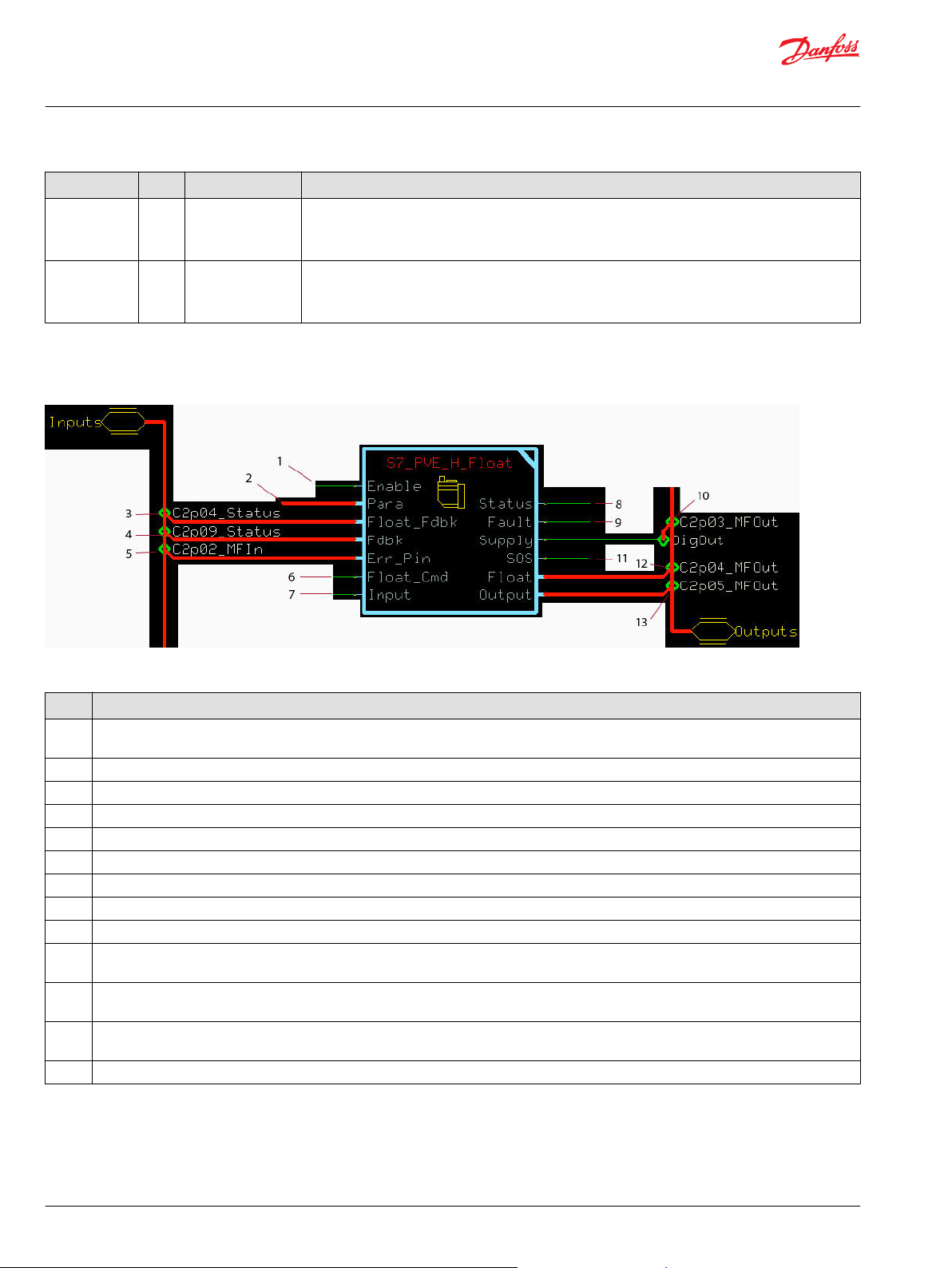
Function Block Connections
The connections that can be made with the function block are described.
S7 PVE H FLOAT Function Block Connections
Item Description
1 T—Enables the Supply output. Releases the Output from its neutral hold.
F—Disables the Supply output. Holds the Output at neutral.
Parameters
2
Reports the status of the MFOut that receives the function block's Float output.
3
4 Reports the status of the MFOut that receives the function block's Output.
5 Input from the valve actuator's Error_Pin. Valve actuator faults set this pin to true.
Command signal to set the Float output.
6
7 Command signal for the actuator spool.
8 Reports the status of the function block.
9 Reports the faults of the function block.
10 True—Actuator spool is in a float state.
False—Sp_Pos output indicates the position of the actuator spool.
11 True—The function block detects no errors in the valve actuator wiring. Power can be shared between this and other actuators.
False—The function block detects an error in the valve actuator wiring. Power must not be applied to the actuator's Supply pin.
12 True— Allow actuator spool to float.
False—The function block's Output controls actuator spool position.
13 Commands the valve actuator.
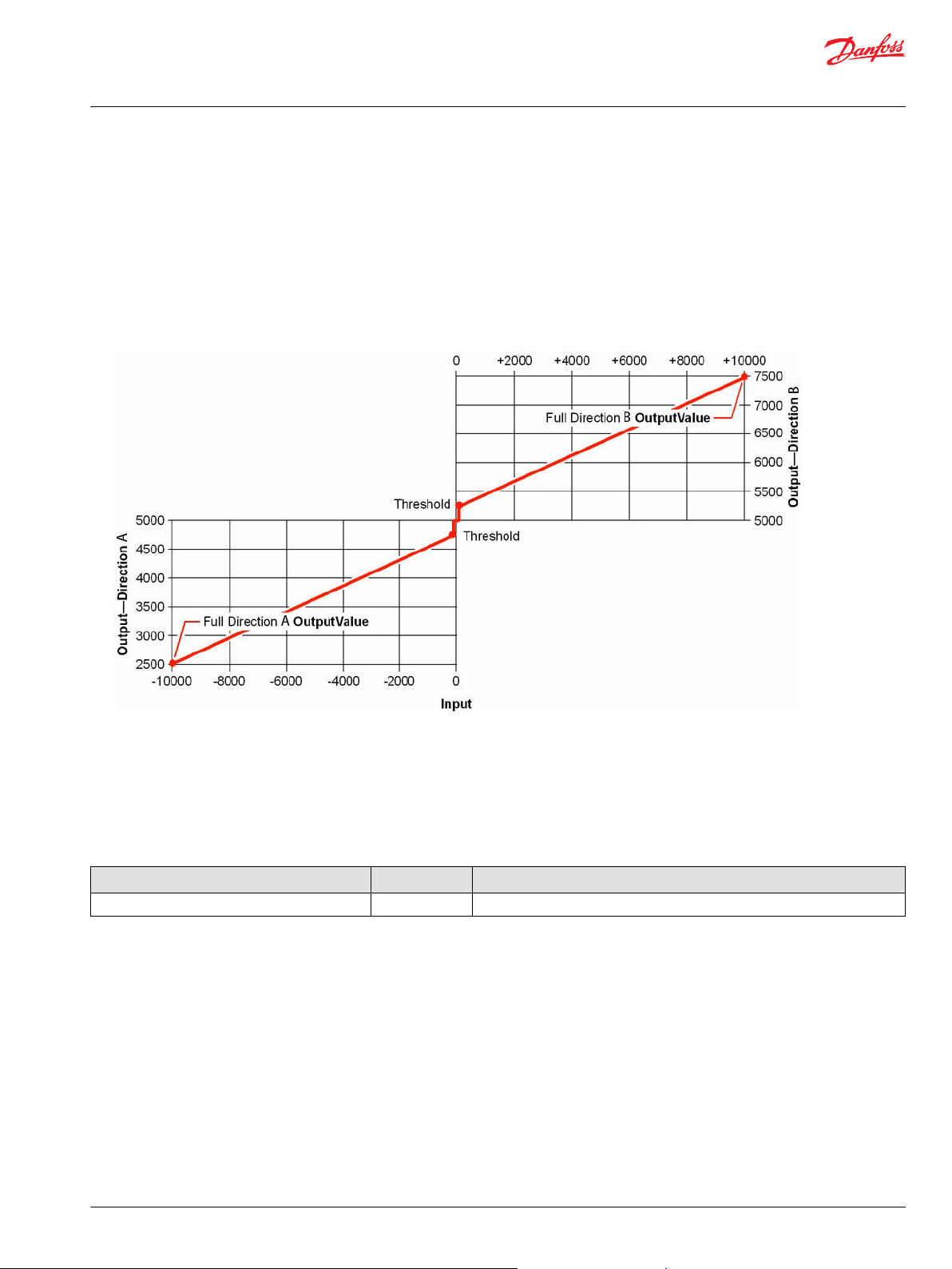
Threshold and Maximum Values
Learn how the output of the function block is determined according to minimum, threshold and
maximum values.
The function block outputs a bus with an OutputValue signal. This signal commands the valve actuator.
6 | © Danfoss | May 2018 AQ00000241en-000102
Page 7
User Manual
PLUS+1® Compliant S7 PVE H Float Function Block
S7_PVE_H_Float Function Block
The following illustration shows a plot of OutputValue signal between its minimum, threshold, and
maximum values.
The range of the OutputValue is 5,000, going 2,500 above and 2,500 below a midpoint of 5,000.
•
In this plot, the Thld value is 10% of the 2,500 value (250).
•
As soon as the Input is +1, the OutputValue jumps to its Direction B threshold value of 5,250.
•
When the Input is +10,000, the OutputValue reaches its full Direction B output value of 7,500.
•
As soon as the Input is –1, the OutputValue jumps to its Direction A threshold value of 4,750.
•
When the Input is –10,000, the OutputValue reaches its full Direction A output value of 2,500.
•
Status and Fault Logic
This topic describes how status logic and fault logic are indicated for the function block.
Status Logic
Status logic determines if parameters are out of order or out of range.
Status Hex
Parameters are not within allowed range. 0x8008 At least one parameter is out of its defined range or in the wrong order.
*
Bit 16 set to 1 identifies a standard Danfossstatus or fault code.
*
Reported While
©
Danfoss | May 2018 AQ00000241en-000102 | 7
Page 8

User Manual
PLUS+1® Compliant S7 PVE H Float Function Block
S7_PVE_H_Float Function Block
Fault Logic
Fault logic helps you determine errors in hardware, inputs or circuits.
Fault Hex*Binary Cause Response Delay
Input value too
low.
Input value too
high.
Short circuit. 0x8008 1000 Controller reports
Hardware. 0x8020 100000 An actuator error
*
Bit 16 set to 1 identifies a standard Danfoss status or fault code.
†
A delayed fault is reported if the detected fault condition persists for a specified delay time. A delayed fault cannot be cleared until the fault condition
remains undetected for the delay time.
‡
The function block maintains a latched fault report until the latch releases. The function block attempts a release each time the Error_Pin is false
while the Input returns to 0.
0x8001 0001 Input value <
‑10,000.
0x8002 0010 Input value >
10,000.
circuit protection.
sets the actuator
valve's Error_Pin
output to true.
Output value =
5,000.
†
Latch‡Correction
No. No.
Yes.
Yes—500
ms delay.
Return the Input value to within its ±10,000
range.
Check for a short circuit or low resistance
between the controller's output pin and the
ground.
Check for an open circuit or high resistance
•
between the controller's output pin and
ground.
Check for a failure in the valve actuator.
•
Power Two or More PVE-Type Valve Actuators from One DigOut
Use the following figure as a connection reference when powering two or more PVE-type valve actuators
from one DigOut.
8 | © Danfoss | May 2018 AQ00000241en-000102
Page 9

User Manual
PLUS+1® Compliant S7 PVE H Float Function Block
S7_PVE_H_Float Function Block
Function Block Connections
Item Description
1 Input commands to the function block.
2 Route all Supply outputs to an OR component.
3 Route all SOS outputs to an AND component.
4 The AND output goes true when:
All SOS outputs are true.
•
At least one Supply output is true.
•
5 Outputs to the Power pins on valve actuators.
6 Outputs to the Output pins on valve actuators.
MC Controller Configurations
Configure inputs and outputs on your controller so they are compatible with the signals of your function
block.
This function block:
•
Receives some of its input signals through your controller's inputs.
•
Outputs some of its output signals through your controller's outputs.
You must configure the inputs and outputs on your controller to be compatible with these signals.
Input Configurations
Function Block Input Compatible Controller Input Type Controller Input Configuration Action
Error_Pin MFIn Delete the PinConfig0 route.
DigAn Delete the PinConfig0 route.
Fdbk MFOut
*
Inside the Inputs page; outputs a Status bus that reports the state of a corresponding MFOut inside the Outputs page.
*
Pair with the MFOut used by the function block's
Output.
Output Configurations
Function Block Output Compatible Controller Output Type Controller Output Configuration Action
Supply MFOut Delete the DigOut route.
DigOut
Output MFOut Delete the:
Delete the DigOut route.
•
OutputValue route.
•
PinConfig route.
©
Danfoss | May 2018 AQ00000241en-000102 | 9
Page 10

User Manual
PLUS+1® Compliant S7 PVE H Float Function Block
S7_PVE_H_Float Function Block
Configure the MFIn for the Error_Pin Input
1. In the PLUS+1® GUIDE template, enter the Inputs page.
2. Enter the MFIn that receives the input signal.
3. Make the changes that are shown in the following figure.
Configure the DigAn for the Error_Pin Input
1. In the PLUS+1® GUIDE template, enter the Inputs page.
2. Enter the DigAn page that receives the input signal.
3. Make the changes that are shown in the following figure.
10 | © Danfoss | May 2018 AQ00000241en-000102
Page 11

User Manual
PLUS+1® Compliant S7 PVE H Float Function Block
S7_PVE_H_Float Function Block
Configure the MFOut for the Supply Output
1. In the GUIDE template, enter the Outputs page.
2. Enter the MFOut that receives the function block’s output.
3. Make the changes that are shown in the following figure.
©
Danfoss | May 2018 AQ00000241en-000102 | 11
Page 12

User Manual
PLUS+1® Compliant S7 PVE H Float Function Block
S7_PVE_H_Float Function Block
Configure the DigOut for the Supply Output
1. In the GUIDE template, enter the Outputs block.
2. Enter the DigOut that receives the function block’s output signal.
3. Make the changes that are shown in the following figure.
12 | © Danfoss | May 2018 AQ00000241en-000102
Page 13

User Manual
PLUS+1® Compliant S7 PVE H Float Function Block
S7_PVE_H_Float Function Block
Configure the MFOut for the Block's Output
1. In the GUIDE template, enter the Outputs page.
2. Enter the MFOut that receives the function block’s output signal.
3. Make the changes that are shown in the following figure.
SC Controller Configurations
Configure inputs and outputs on your controller so they are compatible with the signals of your function
block.
This function block:
•
Receives some of its input signals through your controller's inputs.
•
Outputs some of its output signals through your controller's outputs.
You must configure the inputs and outputs on your controller to be compatible with these signals.
©
Danfoss | May 2018 AQ00000241en-000102 | 13
Page 14

User Manual
PLUS+1® Compliant S7 PVE H Float Function Block
S7_PVE_H_Float Function Block
How to Configure an MFIn for the Error_Pin Input
1. In the PLUS+1® GUIDE template, enter the Inputs page.
2. Enter the MFIn that receives the input signal.
3. Make the changes that are shown in the following figure.
14 | © Danfoss | May 2018 AQ00000241en-000102
Page 15

User Manual
PLUS+1® Compliant S7 PVE H Float Function Block
S7_PVE_H_Float Function Block
How to Configure a DigAn for the Error_Pin Input
1. In the GUIDE template, enter the Inputs page.
2. Enter the DigAn that receives the input signal.
3. Make the changes that are shown in the following figure.
©
Danfoss | May 2018 AQ00000241en-000102 | 15
Page 16

User Manual
PLUS+1® Compliant S7 PVE H Float Function Block
S7_PVE_H_Float Function Block
How to Configure an MFOut for the Supply Output
1. In the GUIDE template, enter the Outputs page.
2. Enter the MFOut that receives the function block’s output signal.
3. Make the changes that are shown in the following figure.
16 | © Danfoss | May 2018 AQ00000241en-000102
Page 17

User Manual
PLUS+1® Compliant S7 PVE H Float Function Block
S7_PVE_H_Float Function Block
How to Configure a DigOut for the Supply Output
1. In the GUIDE template, enter the Outputs block.
2. Enter the DigOut that receives the function block’s output signal.
3. Make the changes that are shown in the following figure.
©
Danfoss | May 2018 AQ00000241en-000102 | 17
Page 18

User Manual
PLUS+1® Compliant S7 PVE H Float Function Block
S7_PVE_H_Float Function Block
How to Configure an MFOut for the Block's Output
1. In the GUIDE template, enter the Outputs page.
2. Enter the MFOut that receives the function block’s output signal.
3. Make the changes that are shown in the following figure.
18 | © Danfoss | May 2018 AQ00000241en-000102
Page 19

User Manual
PLUS+1® Compliant S7 PVE H Float Function Block
S7_PVE_H_Float Function Block
How to Configure an MFOut for the Float Output
1. In the GUIDE template, enter the Outputs page.
2. Enter the MFOut that receives the function block’s output signal.
3. Make the changes that are shown in the following figure.
©
Danfoss | May 2018 AQ00000241en-000102 | 19
Page 20

User Manual
PLUS+1® Compliant S7 PVE H Float Function Block
S7_PVE_H_Float Function Block
How to Configure a DigOut for the Float Output
1. In the GUIDE template, enter the Outputs block.
2. Enter the DigOut that receives the function block’s output signal.
3. Make the changes that are shown in the following figure.
20 | © Danfoss | May 2018 AQ00000241en-000102
Page 21

Danfoss
Power Solutions GmbH & Co. OHG
Krokamp 35
D-24539 Neumünster, Germany
Phone: +49 4321 871 0
Danfoss
Power Solutions ApS
Nordborgvej 81
DK-6430 Nordborg, Denmark
Phone: +45 7488 2222
Danfoss
Power Solutions (US) Company
2800 East 13th Street
Ames, IA 50010, USA
Phone: +1 515 239 6000
Danfoss
Power Solutions Trading
(Shanghai) Co., Ltd.
Building #22, No. 1000 Jin Hai Rd
Jin Qiao, Pudong New District
Shanghai, China 201206
Phone: +86 21 2080 6201
Products we offer:
Hydro-Gear
www.hydro-gear.com
Daikin-Sauer-Danfoss
www.daikin-sauer-danfoss.com
Cartridge valves
•
DCV directional control
•
valves
Electric converters
•
Electric machines
•
Electric motors
•
Gear motors
•
Gear pumps
•
Hydraulic integrated
•
circuits (HICs)
Hydrostatic motors
•
Hydrostatic pumps
•
Orbital motors
•
PLUS+1® controllers
•
PLUS+1® displays
•
PLUS+1® joysticks and
•
pedals
PLUS+1® operator
•
interfaces
PLUS+1® sensors
•
PLUS+1® software
•
PLUS+1® software services,
•
support and training
Position controls and
•
sensors
PVG proportional valves
•
Steering components and
•
systems
Telematics
•
Danfoss Power Solutions is a global manufacturer and supplier of high-quality hydraulic and
electric components. We specialize in providing state-of-the-art technology and solutions
that excel in the harsh operating conditions of the mobile off-highway market as well as the
marine sector. Building on our extensive applications expertise, we work closely with you to
ensure exceptional performance for a broad range of applications. We help you and other
customers around the world speed up system development, reduce costs and bring vehicles
and vessels to market faster.
Danfoss Power Solutions – your strongest partner in mobile hydraulics and mobile
electrification.
Go to www.danfoss.com for further product information.
We offer you expert worldwide support for ensuring the best possible solutions for
outstanding performance. And with an extensive network of Global Service Partners, we also
provide you with comprehensive global service for all of our components.
Local address:
Danfoss can accept no responsibility for possible errors in catalogues, brochures and other printed material. Danfoss reserves the right to alter its products without notice. This also applies to products
already on order provided that such alterations can be made without subsequent changes being necessary in specifications already agreed.
All trademarks in this material are property of the respective companies. Danfoss and the Danfoss logotype are trademarks of Danfoss A/S. All rights reserved.
©
Danfoss | May 2018 AQ00000241en-000102
 Loading...