

User Manual
PLUS+1® Compliant
S7_PVED_ CC_AVC Function Block
www.danfoss.com

User Manual
PLUS+1® Compliant S7_PVED_CC_AVC Function Block
Revision history Table of revisions
Date Changed Rev
September 2020 First edition 0101
2 | © Danfoss | September 2020 AQ342663353837en-000101

User Manual
PLUS+1® Compliant S7_PVED_CC_AVC Function Block
Contents
Abbreviations
S7_PVED_CC_AVC Function Block
Inputs....................................................................................................................................................................................................5
Parameters..........................................................................................................................................................................................5
Outputs................................................................................................................................................................................................ 6
Status Logic........................................................................................................................................................................................ 7
Fault Logic...........................................................................................................................................................................................7
Enabling Checkpoints.....................................................................................................................................................................7
Identical Function Blocks Need Different Namespace Values to Successfully Compile....................................8
Change Namespace Value.......................................................................................................................................................8
Pre-Made Service Screen............................................................................................................................................................... 9
©
Danfoss | September 2020 AQ342663353837en-000101 | 3

User Manual
PLUS+1® Compliant S7_PVED_CC_AVC Function Block
Abbreviations
Abbreviations used in the S7_PVED_CC_AVC function block user manual are described.
Item Description
AVC Auxiliary Valve Command
CC CAN Control
PVED Proportional Valve Electronic Digital
4 | © Danfoss | September 2020 AQ342663353837en-000101

User Manual
PLUS+1® Compliant S7_PVED_CC_AVC Function Block
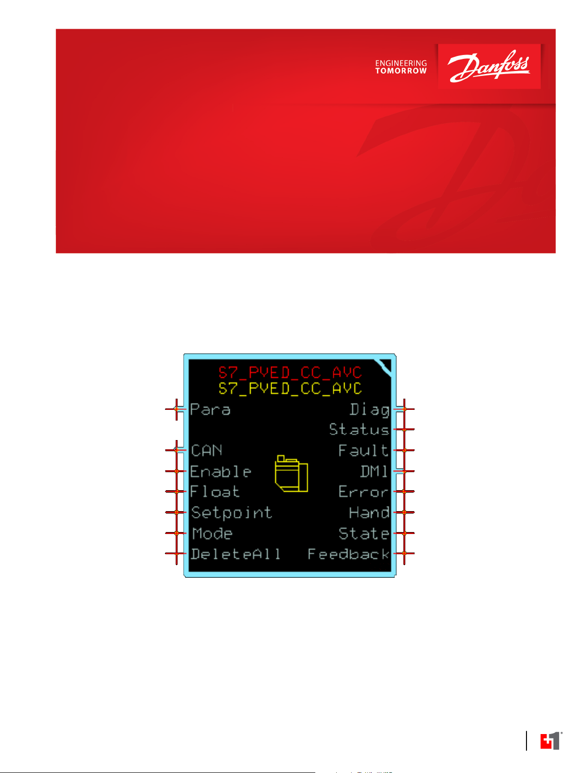
S7_PVED_CC_AVC Function Block
The S7_PVED_CC_AVC function block is intended to be used with the Series 7 PVED-CC actuator for
Danfoss PVG valves.
Inputs
Inputs to the S7_PVED_CC_AVC function block are described.
To avoid compiler errors, use only the data types specified in this table.
Item Type Range Description [Unit]
Port Port —— Determines which CAN port to receive data from and transmit data to. This variable can
be found in the CAN sub-bus if using the Main Template.
Loop_Tm U16 1- 65535 Processing time of one program loop.
[ms]
Enable BOOL T/F Enables CAN transmissions to the valve.
T: Transmit commands based on inputs.
F: Do not transmit commands to the valve.
Float BOOL T/F Enables the Float function of the valve.
T: Valve set to Float, Setpoint ignored.
F: Setpoint used to control valve.
Setpoint S16 -10000-10000 Sets the port flow. This value is scaled between 0 and 250 before sending to the valve. The
sign convention used sets retract when values are less than zero. Flow is blocked when
value is zero.
[0.01%]
Mode U8 1-3 Determines the mode to set the valve into. If value is out of range, mode is set to 3
(Emergency stop).
1: Full operational.
2: Hand operational.
3: Emergency stop.
DeleteAll BOOL T/F Deletes all buffered data from the arrays in the DM1 BUS.
Parameters
The S7_PVED_CC_AVC function block uses parameters to customize how it functions.
To avoid compiler errors, use only the data types specified in this table.
©
Danfoss | September 2020 AQ342663353837en-000101 | 5

User Manual
PLUS+1® Compliant S7_PVED_CC_AVC Function Block
S7_PVED_CC_AVC Function Block
Item Type Range Description [Unit]
NodeId U8 0x80-0x8F CAN bus address of the valve.
SourceIdTx U8 0x00-0xFF Source address of local device.
Default: 0x06.
DLC U8 3 or 8 Number of bytes in AVC message. Non-valid values are set to default.
Default: 8.
Tx_Time U16 10-1000 Sets interval between AVC message transmissions.
Default: 100.
[ms]
Outputs
Outputs of the S7_PVED_CC_AVC function block are described.
Item Type Range Description [Unit]
Diag BUS —— This bus provides diagnostic values for troubleshooting.
Status U16 0x0000, 0x8008 Bitwise code where multiple items can be reported at a time.
0x0000: Status OK.
0x8008: At least one parameter is out of range.
Fault U16 0x0000, 0x8001,
0x8002
DM1 BUS —— This bus provides data from the current active diagnostic
Amber_Lmp_State U8 0-4 Amber Warning Lamp.
Red_Lmp_State U8 0-4 Red Stop Lamp.
Malfctn_Lmp_State U8 0-4 Malfunction Indicator Lamp.
Protect_Lmp_State U8 0-4 Protect Lamp.
SPN_FMI_Addr_Buf
OC_Buffer ARRAY[20]U8
Updated_Buffer
ARRAY[20]U32
ARRAY[20]BOOL
—— Array containing the concatenation of the SPNs, FMIs and
—— Array containing the Occurrence Counts that have been
—— Array whose elements reports true for one loop when the
Bitwise code where multiple items can be reported at a time.
If a value is out of range, all CAN messages being sent keep
the most recent valid data.
0x0000: Status OK.
0x8001: Input value too low.
0x8002: Input value too high.
trouble codes.
0: Off.
1: Solid on.
2: Blink at slow rate (1Hz).
3: Blink at fast rate (2Hz or faster).
0: Off.
1: Solid on.
2: Blink at slow rate (1Hz).
3: Blink at fast rate (2Hz or faster).
0: Off.
1: Solid on.
2: Blink at slow rate (1Hz).
3: Blink at fast rate (2Hz or faster).
0: Off.
1: Solid on.
2: Blink at slow rate (1Hz).
3: Blink at fast rate (2Hz or faster).
Addresses that have been received. Addresses are the lowest
8 bits, FMIs are the next 5 bits and SPN's are the highest 19
bits.
received.
corresponding faults are received.
6 | © Danfoss | September 2020 AQ342663353837en-000101

User Manual
PLUS+1® Compliant S7_PVED_CC_AVC Function Block
S7_PVED_CC_AVC Function Block
Item Type Range Description [Unit]
Valid_Buffer
Total U16 0-20 Total number of faults in the buffer.
BufferOverFlow BOOL T/F True when the buffer is full and another DTC is received and
RawData BUS —— Several additional signals are reported in the RawData bus.
Error BOOL T/F Indicates an error message was received from the valve or
Hand BOOL T/F Indicates Hand Operational mode is active.
State U8 0-3 Indicates the state of the valve.
Feedback S16 -10000-10000 The estimated setpoint received from the valve.
ARRAY[20]BOOL
—— Array whose elements reports true if valid fault information is
stored at that index.
decoded.
These are provided for backward compatibility.
that communication was lost.
T: An error was received in the last 1.5s.
F: No recent error was received.
T: Position error detection and solenoids are disabled.
F: Errors are indicated if hand operated.
0: Blocked.
1: Extend.
2: Retract.
3: Float.
Positive values: Extend.
Negative values: Retract.
[0.01%]
Status Logic
This topic describes how status logic is indicated for the S7_PVED_CC_AVC function block.
The status code indicates whether the parameters used in the function are within their valid range.
Condition Hex Binary Cause Response Correction
Invalid setup.
*
Position of set bit in a 16 bit fault or status code. Bit 1 is the least significant bit. Bit 16 set to 1 indicates a standard Danfoss status code or fault code.
0x8008
*
1000 0000
0000 1000
At least one parameter is out
of range.
Message transmission is
disabled.
Correct the out of range
parameters.
Fault Logic
The fault logic of the S7_PVED_CC function block can indicate problems, causes of problems, and
solutions.
Condition Hex
Input value is too low. 0x8001 1000 0000
Input value is too
high.
*
Position of set bit in a 16 bit fault or status code. Bit 1 is the least significant bit. Bit 16 set to 1 indicates a standard Danfoss status code or fault code.
*
0x8002 1000 0000
Binary Cause Response Correction
0000 0001
0000 0010
An input is too low. Message transmission is
disabled.
An input is too high. Message transmission is
disabled.
Correct the out of range
inputs.
Correct the out of range
inputs.
Enabling Checkpoints
Chkpt enables the checkpoints for each Diag Bus Signal.
It is pre-connected to a constant True.
Set Chkpt to False if you do not want to use the checkpoints or if you need to free up some memory. Be
aware that Fault and Status signals disappear from the service screen by setting to False.
©
Danfoss | September 2020 AQ342663353837en-000101 | 7

W
User Manual
PLUS+1® Compliant S7_PVED_CC_AVC Function Block
S7_PVED_CC_AVC Function Block
Warning
The programmer must implement sufficient fault management and is responsible to reach the safe state
according to the safety concept for the application.
Identical Function Blocks Need Different Namespace Values to Successfully Compile
If you use the same function block more than once in an application, you must change each function
block’s namespace value to avoid compiler errors.
All function blocks contain Advanced Checkpoint with Namespace components that enable the PLUS+1
Service Tool to read block input and output values.
Some function blocks contain non-volatile memory components that store function block operating
parameters.
Both these components use memory names (“aliases”) to allocate memory. Identical memory names
cause compiler errors.
The namespace value adds a unique prefix to each component name to avoid errors. Keep each
namespace value short to save controller memory.
Change Namespace Value
To successfully compile your application, change the namespace value for function blocks that are used
more than once in an application.
®
1. In the PLUS+1® GUIDE menu bar, click the Query/Change button.
2. Click on the function block whose namespace you want to set to a unique value.
The Edit Page window opens.
3. In the Edit Page window, enter a meaningful Namespace value.
Namespace values are case-sensitive.
•
To save controller memory, use a short namespace value.
•
4. Press Enter.
5. Repeat these steps to enter unique namespace values for other identical function blocks.
8 | © Danfoss | September 2020 AQ342663353837en-000101

User Manual
PLUS+1® Compliant S7_PVED_CC_AVC Function Block
S7_PVED_CC_AVC Function Block
Pre-Made Service Screen
This screen gives an overview of the S7_PVED_CC_AVC function block.
Item Description
Inputs ——
Enable Enables CAN transmissions to the valve.
Float Enables the Float function of the valve.
Setpoint Sets the port flow. This value is scaled between 0 and 250 before sending to the valve.
The sign convention used sets retract when values are less than zero. Flow is blocked
when value is zero.
Mode Determines the mode to set the valve into. If value is out of range, mode is set to 3
(Emergency stop).
Parameters ——
NodeId CAN bus address of the valve.
SourceIdTx Source address of local device.
DLC Number of bytes in AVC message. Non-valid values are set to default.
Tx_Time Sets interval between AVC message transmissions.
Outputs ——
Feedback The estimated setpoint received from the valve.
State Indicates the state of the valve.
Error Indicates an error message was received from the valve or that communication was
lost.
Hand Indicates Hand Operational mode is active.
©
Danfoss | September 2020 AQ342663353837en-000101 | 9

User Manual
PLUS+1® Compliant S7_PVED_CC_AVC Function Block
S7_PVED_CC_AVC Function Block
Item Description
Status Reports the status of the function block.
Fault Reports the faults of the function block.
10 | © Danfoss | September 2020 AQ342663353837en-000101

Danfoss
Power Solutions GmbH & Co. OHG
Krokamp 35
D-24539 Neumünster, Germany
Phone: +49 4321 871 0
Danfoss
Power Solutions ApS
Nordborgvej 81
DK-6430 Nordborg, Denmark
Phone: +45 7488 2222
Danfoss
Power Solutions (US) Company
2800 East 13th Street
Ames, IA 50010, USA
Phone: +1 515 239 6000
Danfoss
Power Solutions Trading
(Shanghai) Co., Ltd.
Building #22, No. 1000 Jin Hai Rd
Jin Qiao, Pudong New District
Shanghai, China 201206
Phone: +86 21 2080 6201
Products we offer:
Hydro-Gear
www.hydro-gear.com
Daikin-Sauer-Danfoss
www.daikin-sauer-danfoss.com
Cartridge valves
•
DCV directional control
•
valves
Electric converters
•
Electric machines
•
Electric motors
•
Gear motors
•
Gear pumps
•
Hydraulic integrated
•
circuits (HICs)
Hydrostatic motors
•
Hydrostatic pumps
•
Orbital motors
•
PLUS+1® controllers
•
PLUS+1® displays
•
PLUS+1® joysticks and
•
pedals
PLUS+1® operator
•
interfaces
PLUS+1® sensors
•
PLUS+1® software
•
PLUS+1® software services,
•
support and training
Position controls and
•
sensors
PVG proportional valves
•
Steering components and
•
systems
Telematics
•
Danfoss Power Solutions is a global manufacturer and supplier of high-quality hydraulic and
electric components. We specialize in providing state-of-the-art technology and solutions
that excel in the harsh operating conditions of the mobile off-highway market as well as the
marine sector. Building on our extensive applications expertise, we work closely with you to
ensure exceptional performance for a broad range of applications. We help you and other
customers around the world speed up system development, reduce costs and bring vehicles
and vessels to market faster.
Danfoss Power Solutions – your strongest partner in mobile hydraulics and mobile
electrification.
Go to www.danfoss.com for further product information.
We offer you expert worldwide support for ensuring the best possible solutions for
outstanding performance. And with an extensive network of Global Service Partners, we also
provide you with comprehensive global service for all of our components.
Local address:
Danfoss can accept no responsibility for possible errors in catalogues, brochures and other printed material. Danfoss reserves the right to alter its products without notice. This also applies to products
already on order provided that such alterations can be made without subsequent changes being necessary in specifications already agreed.
All trademarks in this material are property of the respective companies. Danfoss and the Danfoss logotype are trademarks of Danfoss A/S. All rights reserved.
©
Danfoss | September 2020 AQ342663353837en-000101
 Loading...