

Page 1
Data sheet
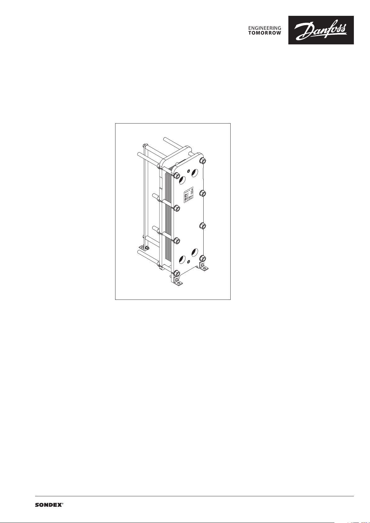
Gasketed Plate Heat Exchangers (DN 50 / 2”)
S7A / S14A / S20A
Description
SONDEX® gasketed plate heat exchangers are
the ideal choice for a wide range of applications
across numerous market segments.
We have the largest plate portfolio in the
world, and we customize each heat exchanger
to meet your exact requirements. Innovative
technologies and smart design make our
gasketed plate heat exchangers a stellar
investment.
Benefits:
• Individually customized solution that
perfectly matches your requirements and
lowers your energy consumption.
• High performance and a low pressure
drop eliminate unnecessary burdens on
your system and optimize overall system
performance.
• The design results in a compact solution with
a small footprint, simple installation, and easy
access for maintenance.
Common applications:
• HVAC industry
• Marine/offshore industry
• Dairy/food/beverage industry
• Sugar industry
• Biogas industry
• Pulp and paper industry
• Heavy industry
• Mining industry
• Petrochemical industry
• Chemical industry
Main data:
• Min. temperature −10 °C
• Max. temperature 180 °C
• Max. working pressure 16 / 25 bar
• Water and different fluids, steam
• Connection size G 2A or DN 50
Approvals:
• Please contact your local Danfoss/SONDEX®
sales representative for an overview of the
available approvals in your region
Construction standard:
• EN13445 (PED 2014/68/EU)
• ASME sec VIII, Div. 1
| 2019.05 VD.JQ.N1.02 | 1
Page 2
Data sheet S7A / S14A / S20A (DN 50)
Naming of units
S14A-IS16-21-TKTL89
3)
1)
1)
Type of heat exchanger:
TKTL89 - Plate grouping
21 - Number of plates in the heat exchanger
16 - Design pressure of the heat exchanger
IS - Frame type
2)
14A – Type of heat exchanger
S – Gasketed heat exchanger
14 - …
Letter A shows type of the attachment of gasket to plate:
e.g. 14 (without A) – SonderLock
14A (with A) – Hang-on
2)
Description of frame types:
There are few different frame types which can be offered for different applications and duties.
IS – with suspension roller,
IG – without suspension roller,
FS – food/sanitary with suspension roller,
FG - food/sanitary,
ST – simple design of frame with threaded connections
3)
Channel grouping:
In this example, the heat exchanger combines TK and TL channels. The share of TL channels equals
89% of the total number of channels.
The number of channels is defined as “the number of plates - 1”.
TK - short thermal length
TM - medium thermal length
TL - long thermal length
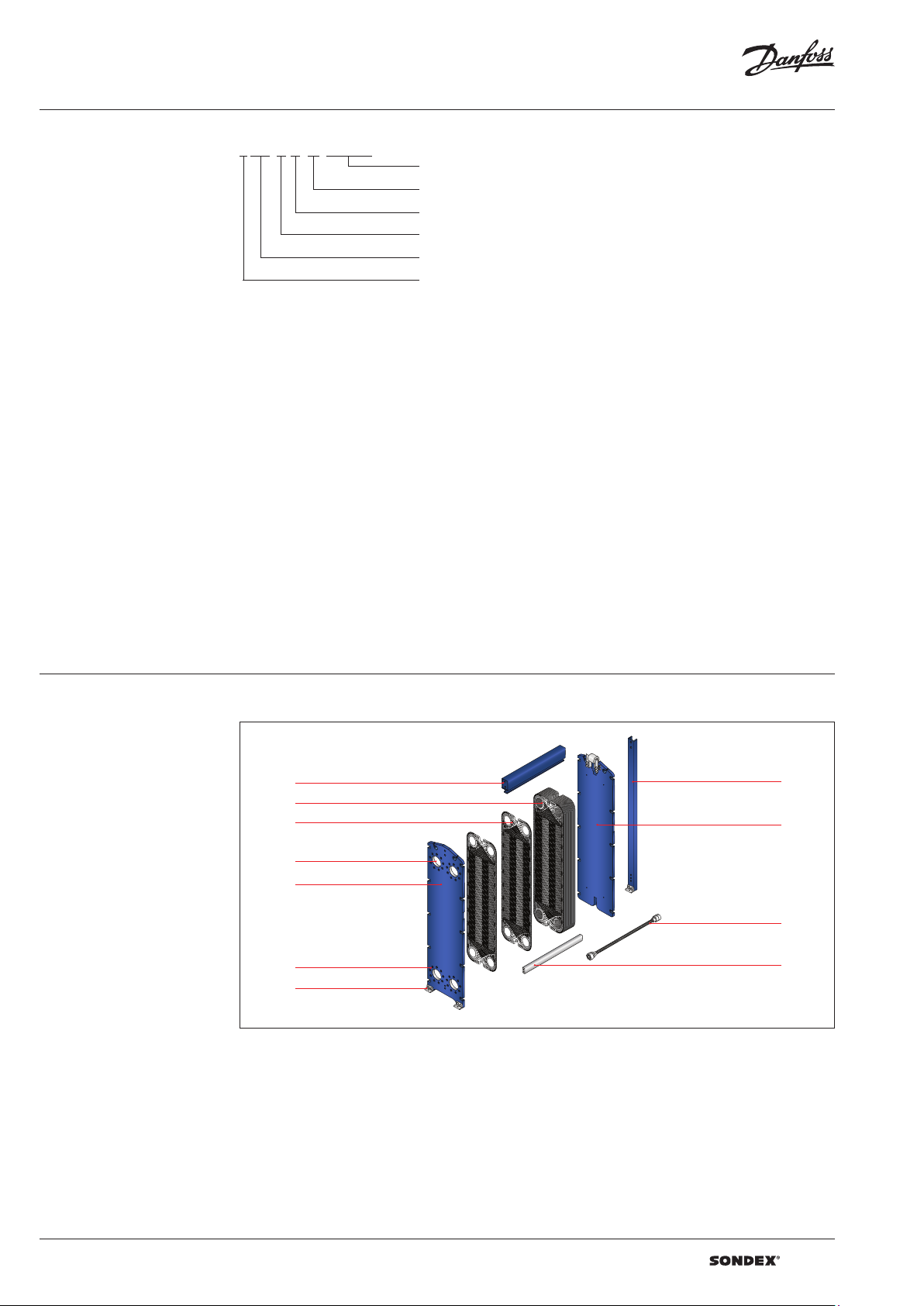
Heat exchanger design
Gasketed heat exchangers consist of
Carrying Bar
Plate Pack
Plate
Connections
Head
Flange Connections
Foundation Feet
Column
Follower
Tie Bolt
Guiding Bar
Anatomy of a SONDEX® plate heat exchanger - IS frame.
2 | VD.JQ.N1.02 | 2019.05
Page 3
Data sheet S7A / S14A / S20A (DN 50)
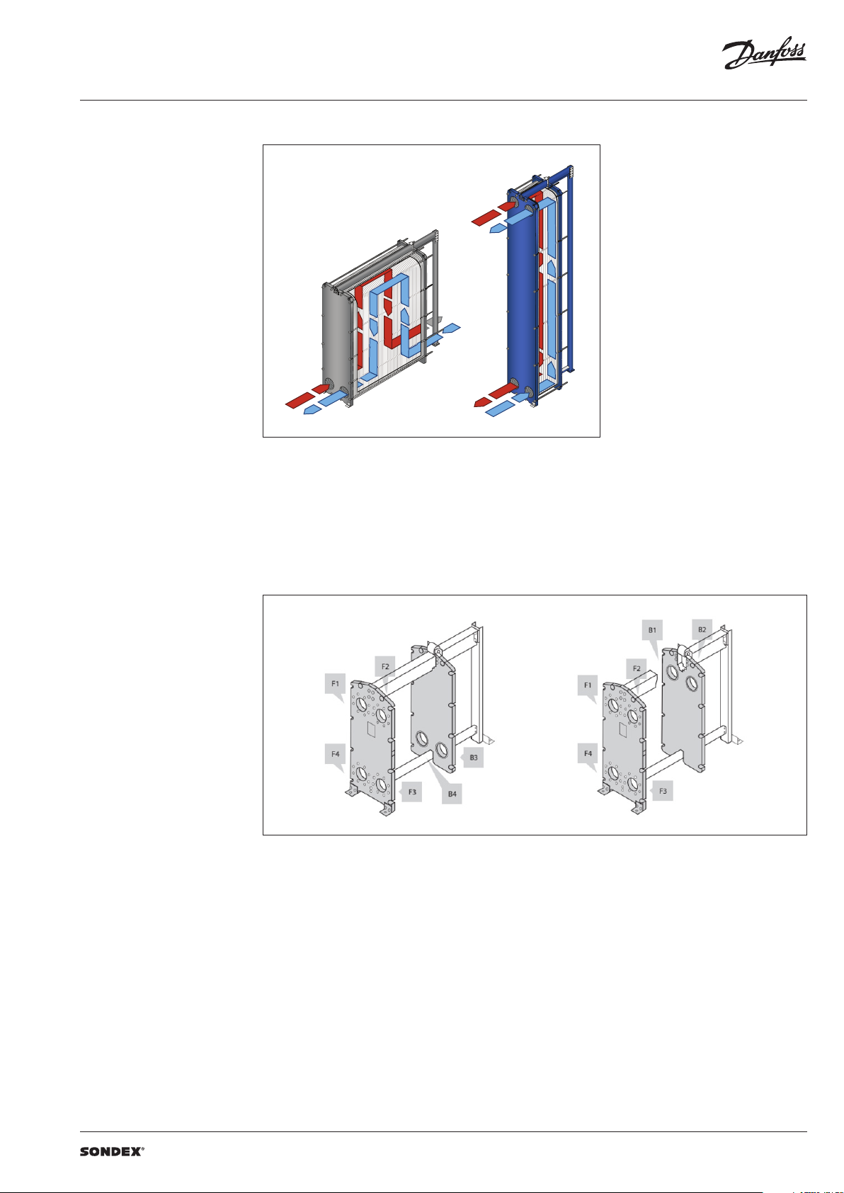
To the left: A multi-pass solution with connections
Heat exchanger design
(continued)
Multi-pass design
on the follower and the head.
To the right: A single-pass solution with
all connections on the head.
Connections
The heat exchanger may have connections on
both front and back-end sides of the unit.
Connections on the front-end plate are marked
with F and connections on the back-end plate
are marked with B. The numbers 1, 2, 3 and 4
designate the position of the connection on the
end-plate from the top-left port clockwise.
VD.JQ.N1.02 | 3 | 2019.05
Page 4
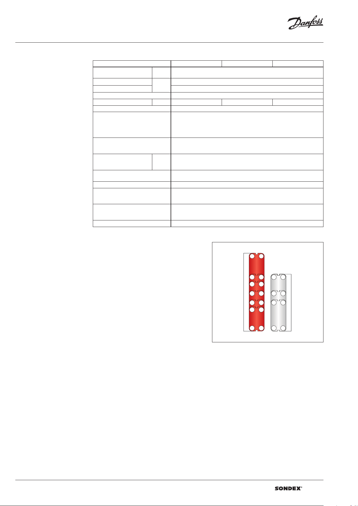
Data sheet S7A / S14A / S20A (DN 50)
SONDEX®
plate
range
Common
Technical data Heat exchanger S7A / S14A / S20A
Typ e S7A S14A S20A
Max. working pressure
Max. operating temperature
Min. operating temperature -10
Flow medium Water and different fluids, steam
Volume / Channel l 0.2 0.35 0.44
Connection size DN 50 / 2"
Connection type
Plate material
Plate thickness mm
Gasket material
Gasket attachment t ype Hang-on
Liners in connections
Frame
Frame painting specification Painting available for corrosion categories C2L, C4M, C5M
1)
SonderSaf e – double plate
PN
(bar)
°C
16, 2 5
Up to 180
• DN 50/2” flanges. Carbon steel, rubberlined or cladded with AISI 316L (other
materials available on request)
• 2” pipe or threaded pip e in stainless steel or titanium
• 2”/DN 50 dairy pipe or union.
According to all known standards
Stainless steel EN 1.440 4 (AISI 316L), EN 1.4301 (AISI 304), SMO254, Hastelloy C276,
titanium Gr.1
Other materials available on request
0.4; 0.5; 0.6
2 x 0.4 SonderSafe plates
Other thicknesses available on request
NBR, EPDM, FKM
Other materials available on request
• Rubber NBR, EPDM, FKM
• Stainless steel EN 1.440 4 (AISI 316L), EN 1.4301 (AISI 304), SMO254, Hastelloy C276,
titanium Gr.1
• Painted frame, color RAL 5010 (other colors available on request)
• Stainless steel frame, designed for the sanitary applications (e.g. food and dairy
industries)
1)
Using the right plate for each individual duty
is very important, as it greatly impacts the
efficiency of the entire installation.
It is important that the length of the plates and
the type of pattern match the requirements of
individual thermal duty.
We have developed a wide plate portfolio to
provide the perfect plate and connection size for
any duty.
No application is too small or too big for us - we
provide the optimal technical solution every
time.
Our extensive SONDEX® plate portfolio
includes plates that lie outside the commonly
manufactured plate sizes to cover all thermal
duties optimally.
plate
range
4 | VD.JQ.N1.02 | 2019.05
Page 5

Data sheet S7A / S14A / S20A (DN 50)
Accessories Insulation
Recommended applications:
The insulation jacket for the plate heat exchanger
is used in different applications with high
temperatures and cooling systems.
Application Heating Cooling
Material
Outer cap
Internal insulation 0.05 mm aluminium foil
Panel fixation Plastic rivets
Temperature 20 … 200 °C -50 … -80 °C
U-value 0.55 W/m2K 0.3 8 W/m2K
Insulation class 3
Heat loss 17.1 W/m
Please note:
Inlet and outl et temperatures in the exch anger have been based on 9 0/50 – 30/70 °C.
1)
The loss of he ating/cooling is stated per m2 surface on the insu lation jacket.
The bottom o f the heat exchanger is not insu lated and this fact has been e xcluded.
A possible loss of ve ntilation, largely dep endent on the mounting of the h eat exchanger, has not been take n into account either.
Drip trays
Recommended applications:
The drip tray is available in two types. A “failsafe” solution which prevents water or liquid
from leaking onto the floor, or when the
heat exchanger is dismantled, or opened for
inspection and maintenance. And an insulated
drip tray for cooling applications, which
collects condensate formed outside of the plate
heat exchanger.
45 mm mineral wool
Not flammable
DIN EN 4102A2
1)
2
40 mm PU-foam
DIN 4102-1 B2
1 mm aluminium
“Stucco” Embossed
1)
4
-
Materials
Drip tray consists of:
• 1 mm galvanized steel frame
• Hanging brackets in galvanized steel
• 60 mm Polyurethane insulation for cooling
applications
• Draining valve.
Spare parts
Spare parts for gasketed heat exchangers, such
as plates, gaskets, frame parts can be ordered for
maintenance, repair, increasing heat exchanger
capacity, etc.
Selection and ordering Please contact your local SONDEX® or Danfoss
sales representative for the selection and / or
ordering of the heat exchangers, spare parts and
accessories.
Please contact your local Danfoss or SONDEX®
sales representative to provide you with
information on spare parts available for gasketed
heat exchangers.
For contact information please visit
https://www.danfoss.com/en/contact-us.
VD.JQ.N1.02 | 5 | 2019.05
Page 6

Data sheet S7A / S14A / S20A (DN 50)
Dimensions
Non-sanitary applications
Any connection can be used for primary side in.
All the rest are made correspondingly.
S7A fr ames
126
140
F1 F2
394
F4
F3
160
W
5
20 20
60
30
Ø50
L + 100
L + 60
L1
B1
B2
394
B3
25
25
5
H
B4
5050 L
260
Ø18
Drawing of S7A IS16 frame
Number of plates
L (Frame length)
1)
(mm)
W
(mm)
H
(mm)
Weight max, empt y
(kg)
2)
Connection type
S7A I S16
3)
7 - 39
40 - 76
77 - 150
151 - 206
207 - 243
244 - 336
3)
3)
3)
3)
3)
429
111
629 135
1029 181
1329 215
300
11.81”
745
(29.33”)
1529 240
2029 297
DN 50 flange or 2”
threaded pipe BSP
S7A I G16
7 - 50 437
70 - 87 637 139
300
11.81”
694
(2 7.32”)
116
2” threaded pipe BSP51 - 69 537 127
S7A S T16
7 – 40 437
41 – 59 537 103
60 – 77 637 113
1)
the indicate d maximum number of pla tes is based on the minimum plate thi ckness allowable for the PN le vel of the unit;
2)
the maximum w eight of the empty unit with t he maximum allowable nu mber of plates;
3)
maximum nu mber of plates is indicated for t he unit without intermediate f rame. Adding intermedia te frame reduces maximum
283
(11.14 ”)
596
(23.4 6”)
93
2” NPT
ISO7-R2/BSP
allowable nu mber of plates in the unit.
6 | VD.JQ.N1.02 | 2019.05
Page 7

Data sheet S7A / S14A / S20A (DN 50)
Dimensions (continued)
Non-sanitary applications
S14A frames
126
Ø50
L1
140160 694
B2
F1
F2
B1
H
994
F4
F3
5
W
25
L
5
25
5050
B3
B4
L + 100
L + 60 20
Ø18
60
30
260
Ø18
Drawing of S14A IS16 frame
Number of plates
L (Frame length)
1)
(mm)
W
(mm)
H
(mm)
Weight max, empt y
(kg)
2)
Connection type
S14A IS16
3)
7 - 39
3)
40 - 76
77 - 150
151 - 206
207 - 243
244 - 336
337 – 428
429 - 521
3)
3)
3)
3)
3)
3)
429
170
629 205
1029 277
1329 331
1529 366
300
11.81”
104 4.6
41.13”
2029 455
2529 545
3029 633
DN 50 flange / 2”
threaded pipe BSP
S14A IS25
3)
7 – 35
36 – 71
72 – 142
143 – 196
197 – 232
233 – 321
322 – 410
411 – 500
3)
3)
3)
3)
3)
3)
3)
444
178
644 223
104 4 314
134 4 383
154 4 428
300
11.81”
104 4.6
41.13”
2044 542
2544 655
3044 769
DN 50 flange / 2”
threaded pipe BSP
S14A IG16
7 – 50 437
51 – 69 537 187
70 – 87 637 204
300
11.81”
994
39.13 ”
170
2” NPT
ISO7-R2/BSP
S14A ST16
7 - 40 437
41 - 59 537 159
60 – 77 637 175
1)
the indicate d maximum number of pla tes is based on the minimum plate thi ckness allowable for the PN le vel of the unit;
2)
the maximum w eight of the empty unit with t he maximum allowable nu mber of plates;
3)
maximum nu mber of plates is indicated for t he unit without intermediate f rame. Adding intermedia te frame reduces maximum
allowable nu mber of plates in the unit.
283
(11.14 ”)
896
(35.28”)
144
2” NPT
ISO7-R2/BSP
VD.JQ.N1.02 | 7 | 2019.05
Page 8

Data sheet S7A / S14A / S20A (DN 50)
Dimensions (continued)
Non-sanitary applications
S20A frames
126
Ø50
L1
140
B1
F2
F1
B2
H
F3
F4
160 894
W
5
50 50
25
L
5
25
B4
B3
L + 100
L + 60 2020
Ø18
30
260
Ø18
Drawing of S20A IS16 frame
Number of plates
L (frame length)
1)
(mm)
W
(mm)
H
(mm)
Weight max, empt y
(kg)
2)
Connection type
S20A IS16
3)
7 – 39
40 – 76
77 – 150
151 – 206
207 – 243
244 - 336
3)
3)
3)
3)
3)
429
201
629 242
1029 326
1329 389
300
11.81”
124 4.6
(49”)
1529 430
2029 534
DN 50 flange / 2”
threaded pipe BSP
S20A IS25
3)
7 – 37
38 – 73
74 – 144
145 – 198
199 – 233
234 - 323
3)
3)
3)
3)
3)
434
242
634 296
1034 404
1334 485
300
(11.81 ”)
124 4.6
(49”)
1534 539
2034 675
DN 50 flange / 2”
threaded pipe BSP
S20A IG16
7 – 50 437
51 – 69 537 223
70 - 87 637 242
300
(11.81 ”)
119 4
(4 7.01”)
203
DN 50 flange / 2”
threaded pipe BSP
S20A ST16
7 – 40 437
41 – 59 537 198
60 - 77 637 218
1)
the indicate d maximum number of pla tes is based on the minimum plate thi ckness allowable for the PN le vel of the unit;
2)
the maximum w eight of the empty unit with t he maximum allowable nu mber of plates;
3)
the indicated ma ximum number of plates is fo r units without intermedi ate frames. Adding an interm ediate frame reduces the
283
(11.14 ”)
1096
(43 .15”)
178
2” NPT
ISO7-R2/BSP
maximum all owable number of plates in t he unit;
8 | VD.JQ.N1.02 | 2019.05
Page 9

Data sheet S7A / S14A / S20A (DN 50)
Dimensions (continued)
Sanitary applications
S7A fr ames
50140394251
= =
126
674111
L - 38
L
L1
= =
126
H
394251
W
Drawing of S7A FS16 frame
Number of plates
L (frame length)
1)
(mm)
W
(mm)
H
(mm)
Weight max, empt y
(kg)
2)
Connection type
S7A F S16
3)
7 – 50
51 – 87
88 – 162
163 – 217
218 – 254
255 – 347
3)
3)
3)
3)
3)
455
122
655 146
1055 19 6
1355 232
300
(11.81 ”)
835
(32.87 ”)
1555 257
2055 317
DN50 dairy union
DIN / 2’’ dair y union
S7A F G16
7 – 50 455
51 – 69 555 112
70 - 87 655 122
1)
the indicate d maximum number of pla tes is based on the minimum plate thi ckness allowable for the PN le vel of the unit;
2)
the maximum w eight of the empty unit with t he maximum allowable nu mber of plates;
3)
the indicated ma ximum number of plates is fo r units without intermedi ate frames. Adding an interm ediate frame reduces the
maximum all owable number of plates in t he unit;
4)
The height of th e heat exchanger can be mo dified with special adj ustable feet.
300
(11.81 ”)
729.5
(28.72”)
4)
102
DN50 dairy union
DIN / 2’’ dair y union
VD.JQ.N1.02 | 9 | 2019.05
Page 10

Data sheet S7A / S14A / S20A (DN 50)
Dimensions (continued)
Sanitary applications
S14A fra mes
974
106/13 6
min/max
126
F1
F4 F3
260
Ø70
F2
L1
B1
B2
H
B3
B4
140 694 140
25
L - 27.50
W
140 694 140
L
M2
M1
W
min. 13 plates between
intermediate frames
Drawing of S14A FS16 frame
Number of plates
L (frame length)
1)
(mm)
W
(mm)
H
(mm)
Weight max, empt y
(kg)
2)
Connection type
S14A FS16
3)
7 – 50
51 – 87
88 – 162
162 – 217
218 – 254
254 – 347
3)
3)
3)
3)
3)
455
185
655 229
1055 320
1355 385
300
(11.81 ”)
1170 – 1200
(4 6. 06”- 47. 24” )
4)
1555 429
2055 541
DN50 dairy union
DIN / 2’’ dair y union
S14A FG16
7 – 50 455
51 – 69 555 208
70 - 87 655 230
1)
the indicate d maximum number of pla tes is based on the minimum plate thi ckness allowable for the PN le vel of the unit;
2)
the maximum w eight of the empty unit with t he maximum allowable nu mber of plates;
3)
the indicated ma ximum number of plates is fo r units without intermedi ate frames. Adding an interm ediate frame reduces the
maximum all owable number of plates in t he unit,
4)
the height of the h eat exchanger can be mod ified with special adj ustable feet.
300
(11.81 ”)
1025 – 1055
(40. 35”- 41.54 ”)
4)
185
DN50 dairy union
DIN / 2’’ dair y union
10 | VD.JQ.N1.02 | 2019.05
Page 11

Data sheet S7A / S14A / S20A (DN 50)
Dimensions (continued)
Sanitary applications
S20A frames
894 140
140
Drawing of S20A FS16
L - 27.5
L1
126
100 ± 5
B1
B2
H
B3
25
894 140
B4
140
126
Ø70
90
F2
F1
1174
F3
F4
100 ± 5
25
285
106/13 6
min/max
L
M1
M2
W
min. 13 plates between
intermediate frames
Number of plates
L (frame length)
1)
(mm)
W
(mm)
H
(mm)
Weight max, empt y
(kg)
2)
Connection type
S20A FS16
3)
7 – 50
51 – 87
88 – 162
163 – 217
218 – 254
255 – 347
3)
3)
3)
3)
3)
455
208
655 250
1055 334
1355 396
325
(12.8 0”)
1370 – 1400
(53.94”-55.12”)
4)
1555 438
2055 542
DN50 dairy union
DIN / 2’’ dair y union
S20A FG16
7 – 50 455
51 – 69 555 215
70 - 87 655 234
1)
the indicate d maximum number of pla tes is based on the minimum plate thi ckness allowable for the PN le vel of the unit.
2)
the maximum w eight of the empty unit with t he maximum allowable nu mber of plates;
3)
the indicated ma ximum number of plates is fo r units without intermedi ate frames. Adding an interm ediate frame reduces the
maximum all owable number of plates in t he unit;
4)
the height of the h eat exchanger can be mod ified with special adj ustable feet.
300
(11.81 ”)
1225 – 1255
(48. 23”- 49.41”)
4)
195
DN50 dairy union
DIN / 2’’ dair y union
Notes to d rawings
Drawings are onl y for reference.
Please contact you r local SONDEX® or Danfos s sales representative for detai led drawings.
VD.JQ.N1.02 | 11 | 2019.05
Page 12

Data sheet S7A / S14A / S20A (DN 50)
| DHS-SRMT/SI | 2019.0512 | VD.JQ.N1.02
 Loading...