

User Manual
PLUS+1® GUIDE Compliant
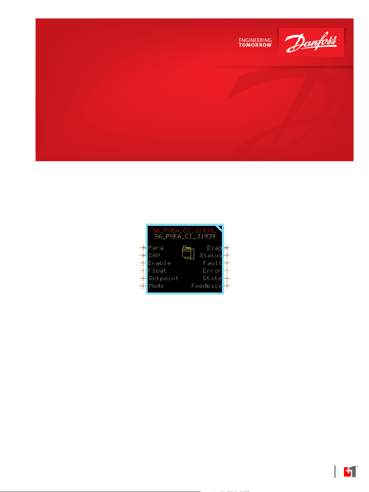
S6_PVEA_CI_J1939 Function Block
www.danfoss.com
User Manual
PLUS+1® Compliant S6_PVEA_CI_J1939 Function Block User Manual
Revision history Table of revisions
Date Changed Rev
January 2020 First edition 0101
2 | © Danfoss | January 2020 AQ294981024053en-000101

User Manual
PLUS+1® Compliant S6_PVEA_CI_J1939 Function Block User Manual
Contents
S6_PVEA_CI_J1939 Function Block
Inputs....................................................................................................................................................................................................4
Function Block Parameters........................................................................................................................................................... 5
Outputs................................................................................................................................................................................................ 5
Enabling Checkpoints.....................................................................................................................................................................5
Identical Function Blocks Need Different Namespace Values to Successfully Compile....................................6
Change Namespace Value.......................................................................................................................................................6
Customizable Service Screens..................................................................................................................................................... 6
S6 PVEA-CI J1939 Detailed Service Tool Screen...............................................................................................................7
S6 PVEA-CI J1939 Reusable Service Tool Screen..............................................................................................................8
©
Danfoss | January 2020 AQ294981024053en-000101 | 3

User Manual
PLUS+1® Compliant S6_PVEA_CI_J1939 Function Block User Manual
S6_PVEA_CI_J1939 Function Block
Use the S6_PVEA_CI_J1939 function block to control a hydraulic valve.
The S6_PVEA_CI_J1939 function block uses CAN messages to control the valve actuator.
The function block contains CAN Rx symbols that receive emergency messages. The filters are set to
receive the messages from the specified NodeId.
Functional and safety interlocks are not handled in this function block.
Input data types must exactly match the indicated type for a successful compile.
Hand operation mode is not available on all PVEA-CIs.
Inputs
Inputs to the S6_PVEA_CI_J1939 function block are described.
Item Type Range Description [Unit]
Para BUS —— BUS where configuration values can be adjusted or the values can be replaced with signals routed from the
application.
Port Port ——
Loop Tm U16 1-65535 Processing time of one program loop.
Float BOOL T/F Enable the Float function of the valve.
Enable BOOL T/F Enable CAN transmissions to the valve.
Setpoint S16 -10000-
10000
Mode U8 1-3 The mode to which the valve is set.
CAN port that receives messages from the valve and transmits commands to the valve.
[ms]
T: Valve set to the Float position. Setpoint ignored.
F: Setpoint used to control the valve.
T: Enables CAN transmissions to the valve.
F: Do not transmit commands to the valve.
Sets the port flow. This value is scaled between 0 and 250 before sending it to the valve.
Positive values: Extend.
Negative values: Retract.
0: Blocked.
[0.01%]
If the value is out of range, the mode is set to 3, emergency stop.
1: Full operational.
2: Hand operational.
3: Emergency stop.
4 | © Danfoss | January 2020 AQ294981024053en-000101

W
User Manual
PLUS+1® Compliant S6_PVEA_CI_J1939 Function Block User Manual
S6_PVEA_CI_J1939 Function Block
Function Block Parameters
Use Para BUS signals to change the operating characteristics of the S6_PVEA_CI_J1939 function block.
Input Type Range Description [Unit]
NodeId U8 128-143 CAN bus address of the valve.
SourceIdTx U8 0-255 Source address of local device.
Default: 6.
DLC
Tx_Time
Outputs
Item Type Range Description [Unit]
Diag BUS —— BUS that provides diagnostic values for troubleshooting.
Status
Fault
Error BOOL T/F Indicates an error message was received from the valve.
State U8 0-14
Feedback S16 -10000-10000 Estimated setpoint received from the valve. This value is scaled from 125 and 225 after
U8 3 or 8 Number of bytes in AVC message.
Non-valid values are set to default.
Default: 8.
U16 10-1000 Sets interval between AVC message transmissions.
Default: 100.
[ms]
Outputs of the S6_PVEA_CI_J1939 function block are described.
U16
U16
—— Bitwise code where multiple items can be reported at a time.
0x0000: Status OK.
0x8008: A parameter is out of range.
—— Bitwise code where multiple items can be reported at a time. If a value is out of range, all
CAN messages being sent keep the most recent valid data.
0x0000: Status OK.
0x8001: Input value too low.
0x8002: Input value too high.
T: The valve reported an error within the last 1.5 seconds.
F: No recent error received.
Indicates the current state of the S6_PVEA_CI_J1939 valve actuator.
0: Blocked.
1: Extend.
2: Retract.
3: Float.
10: Hand operation.
14: Emergency stop.
the value is received.
Positive values: Extend.
Negative values: Retract.
0: Blocked.
[0.01%]
Enabling Checkpoints
Chkpt enables the checkpoints for each Diag Bus Signal.
It is pre-connected to a constant True.
Set Chkpt to False if you do not want to use the checkpoints or if you need to free up some memory. Be
aware that Fault and Status signals disappear from the service screen by setting to False.
Warning
The programmer must implement sufficient fault management and is responsible to reach the safe state
according to the safety concept for the application.
©
Danfoss | January 2020 AQ294981024053en-000101 | 5

User Manual
PLUS+1® Compliant S6_PVEA_CI_J1939 Function Block User Manual
S6_PVEA_CI_J1939 Function Block
Identical Function Blocks Need Different Namespace Values to Successfully Compile
If you use the same function block more than once in an application, you must change each function
block’s namespace value to avoid compiler errors.
All function blocks contain Advanced Checkpoint with Namespace components that enable the PLUS+1
Service Tool to read block input and output values.
Some function blocks contain non-volatile memory components that store function block operating
parameters.
Both these components use memory names (“aliases”) to allocate memory. Identical memory names
cause compiler errors.
The namespace value adds a unique prefix to each component name to avoid errors. Keep each
namespace value short to save controller memory.
Change Namespace Value
To successfully compile your application, change the namespace value for function blocks that are used
more than once in an application.
®
1. In the PLUS+1® GUIDE menu bar, click the Query/Change button.
2. Click on the function block whose namespace you want to set to a unique value.
The Edit Page window opens.
3. In the Edit Page window, enter a meaningful Namespace value.
Namespace values are case-sensitive.
•
To save controller memory, use a short namespace value.
•
4. Press Enter.
5. Repeat these steps to enter unique namespace values for other identical function blocks.
Customizable Service Screens
This function block comes with pre-made service screens that you can customize when building your
Service Tool application.
The pre-made screens simplify the task of creating Service Tool applications. You can use the screens as
is. Or, you can choose screen components to place in your application.
6 | © Danfoss | January 2020 AQ294981024053en-000101

User Manual
PLUS+1® Compliant S6_PVEA_CI_J1939 Function Block User Manual
S6_PVEA_CI_J1939 Function Block
Refer to the PLUS+1® GUIDE Service Tool Design Manual (Danfoss document number L1320837) for more
information on how to create Service Tool screens.
S6 PVEA-CI J1939 Detailed Service Tool Screen
Use the detailed S6 PVEA-CI J1939 service tool screen to determine how the function block and valve
are operating.
Item Description
Inputs ——
Enable Indicates if commands are transmitted.
Float Indicates if the Float function of the valve is enabled.
Setpoint Sets the port flow.
Mode The mode to set the valve into.
Parameters ——
NodeID CAN bus address of the valve.
SourceIdTx Source address of local device.
Tx_Time The interval between AVC message transmissions.
Outputs ——
Status Bitwise code where multiple items can be reported at a time.
Fault Bitwise code where multiple items can be reported at a time.
©
Danfoss | January 2020 AQ294981024053en-000101 | 7

User Manual
PLUS+1® Compliant S6_PVEA_CI_J1939 Function Block User Manual
S6_PVEA_CI_J1939 Function Block
Item Description
Error Indicates if an error message was received from the valve.
State The state of the valve.
Feedback The estimated setpoint received from the valve.
S6 PVEA-CI J1939 Reusable Service Tool Screen
Use the reusable S6 PVEA-CI J1939 service tool screen to determine how the function block and valve
are operating.
Item Description
Enable Indicates if commands are transmitted.
Float Indicates if the Float function of the valve is enabled.
Setpoint Sets the port flow.
Mode The mode to set the valve into.
NodeID CAN bus address of the valve.
SourceIdTx Source address of local device.
Tx_Time The interval between AVC message transmissions.
Status Bitwise code where multiple items can be reported at a time.
Fault Bitwise code where multiple items can be reported at a time.
Error Indicates if an error message was received from the valve.
State The state of the valve.
Feedback The estimated setpoint received from the valve.
8 | © Danfoss | January 2020 AQ294981024053en-000101

Danfoss
Power Solutions GmbH & Co. OHG
Krokamp 35
D-24539 Neumünster, Germany
Phone: +49 4321 871 0
Danfoss
Power Solutions ApS
Nordborgvej 81
DK-6430 Nordborg, Denmark
Phone: +45 7488 2222
Danfoss
Power Solutions (US) Company
2800 East 13th Street
Ames, IA 50010, USA
Phone: +1 515 239 6000
Danfoss
Power Solutions Trading
(Shanghai) Co., Ltd.
Building #22, No. 1000 Jin Hai Rd
Jin Qiao, Pudong New District
Shanghai, China 201206
Phone: +86 21 2080 6201
Products we offer:
Hydro-Gear
www.hydro-gear.com
Daikin-Sauer-Danfoss
www.daikin-sauer-danfoss.com
DCV directional control
•
valves
Electric converters
•
Electric machines
•
Electric motors
•
Gear motors
•
Gear pumps
•
Hydrostatic motors
•
Hydrostatic pumps
•
Orbital motors
•
PLUS+1® controllers
•
PLUS+1® displays
•
PLUS+1® joysticks and
•
pedals
PLUS+1® operator
•
interfaces
PLUS+1® sensors
•
PLUS+1® software
•
PLUS+1® software services,
•
support and training
Position controls and
•
sensors
PVG proportional valves
•
Steering components and
•
systems
Telematics
•
Danfoss Power Solutions is a global manufacturer and supplier of high-quality hydraulic and
electric components. We specialize in providing state-of-the-art technology and solutions
that excel in the harsh operating conditions of the mobile off-highway market as well as the
marine sector. Building on our extensive applications expertise, we work closely with you to
ensure exceptional performance for a broad range of applications. We help you and other
customers around the world speed up system development, reduce costs and bring vehicles
and vessels to market faster.
Danfoss Power Solutions – your strongest partner in mobile hydraulics and mobile
electrification.
Go to www.danfoss.com for further product information.
We offer you expert worldwide support for ensuring the best possible solutions for
outstanding performance. And with an extensive network of Global Service Partners, we also
provide you with comprehensive global service for all of our components.
Local address:
Danfoss can accept no responsibility for possible errors in catalogues, brochures and other printed material. Danfoss reserves the right to alter its products without notice. This also applies to products
already on order provided that such alterations can be made without subsequent changes being necessary in specifications already agreed.
All trademarks in this material are property of the respective companies. Danfoss and the Danfoss logotype are trademarks of Danfoss A/S. All rights reserved.
©
Danfoss | January 2020 AQ294981024053en-000101
 Loading...