

Page 1
Data sheet
Gasketed Plate Heat Exchangers (DN 250 / 10”)
S67 / S113 / S155
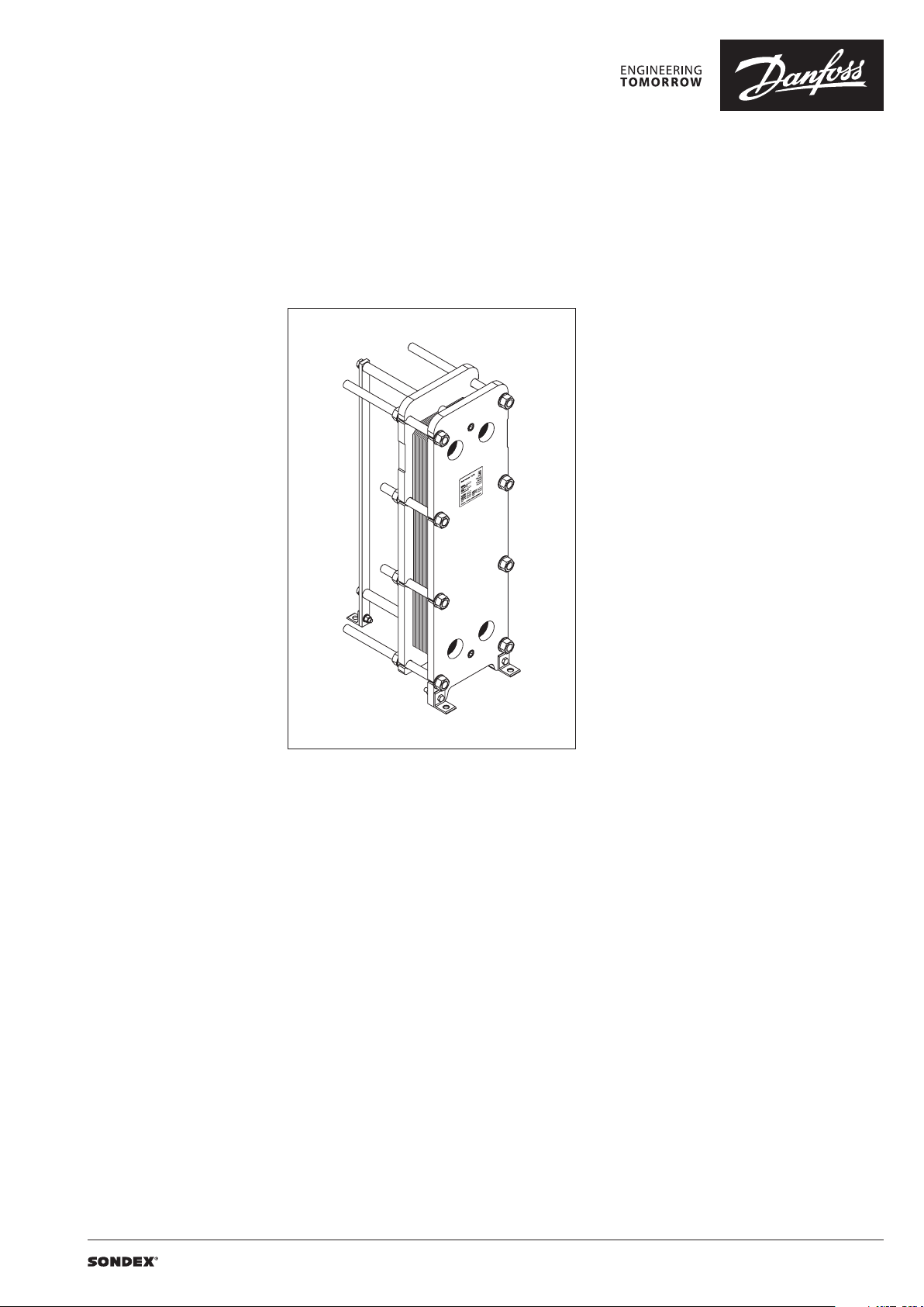
Description
SONDEX® gasketed plate heat exchangers are
the ideal choice for a wide range of applications
across numerous market segments.
We have the largest plate portfolio in the
world, and we customize each heat exchanger
to meet your exact requirements. Innovative
technologies and smart design make our
gasketed plate heat exchangers a stellar
investment.
Benefits:
• Individually customized solution that
perfectly matches your requirements and
lowers your energy consumption.
• High performance and a low pressure
drop eliminate unnecessary burdens on
your system and optimize overall system
performance.
• The design results in a compact solution with
a small footprint, simple installation, and easy
access for maintenance.
Common applications:
• HVAC industry
• Marine/offshore industry
• Dairy/food/beverage industry
• Sugar industry
• Biogas industry
• Pulp and paper industry
• Heavy industry
• Mining industry
• Petrochemical industry
• Chemical industry
Main data:
• Min. temperature −10 °C
• Max. temperature 180 °C
• Max. working pressure 16 / 25 bar (10 bar on
request)
• Water and different fluids, steam
• Connection size DN 250 or 10”
Approvals:
• Please contact your local Danfoss/SONDEX®
sales representative for an overview of the
available approvals in your region
Construction standard:
• EN13445 (PED 2014/68/EU)
• ASME sec VIII, Div. 1
| 2019.07 VD.JQ.S1.02 | 1
Page 2
Data sheet S67 / S113 / S155 (DN 250)
Naming of units
S67-IS16-21-TKTL89
3)
1)
1)
Type of heat exchanger:
TKTL89 - Plate grouping
21 - Number of plates in the heat exchanger
16 - Design pressure of the heat exchanger
IS - Frame type
2)
67 – Type of heat exchanger
S – Gasketed heat exchanger
67 - …
Letter S67 shows type of the attachment of gasket to plate:
e.g. 67 (without A) – SonderLock
67A (with A) – Hang-on
2)
Description of frame types:
There are few different frame types which can be offered for different applications and duties.
IS – with suspension roller,
IG – without suspension roller,
FS – food/sanitary with suspension roller,
FG - food/sanitary,
ST – simple design of frame with threaded connections
3)
Channel grouping:
In this example, the heat exchanger combines TK and TL channels. The share of TL channels equals
89% of the total number of channels.
The number of channels is defined as “the number of plates - 1”.
TK - short thermal length
TM - medium thermal length
TL - long thermal length
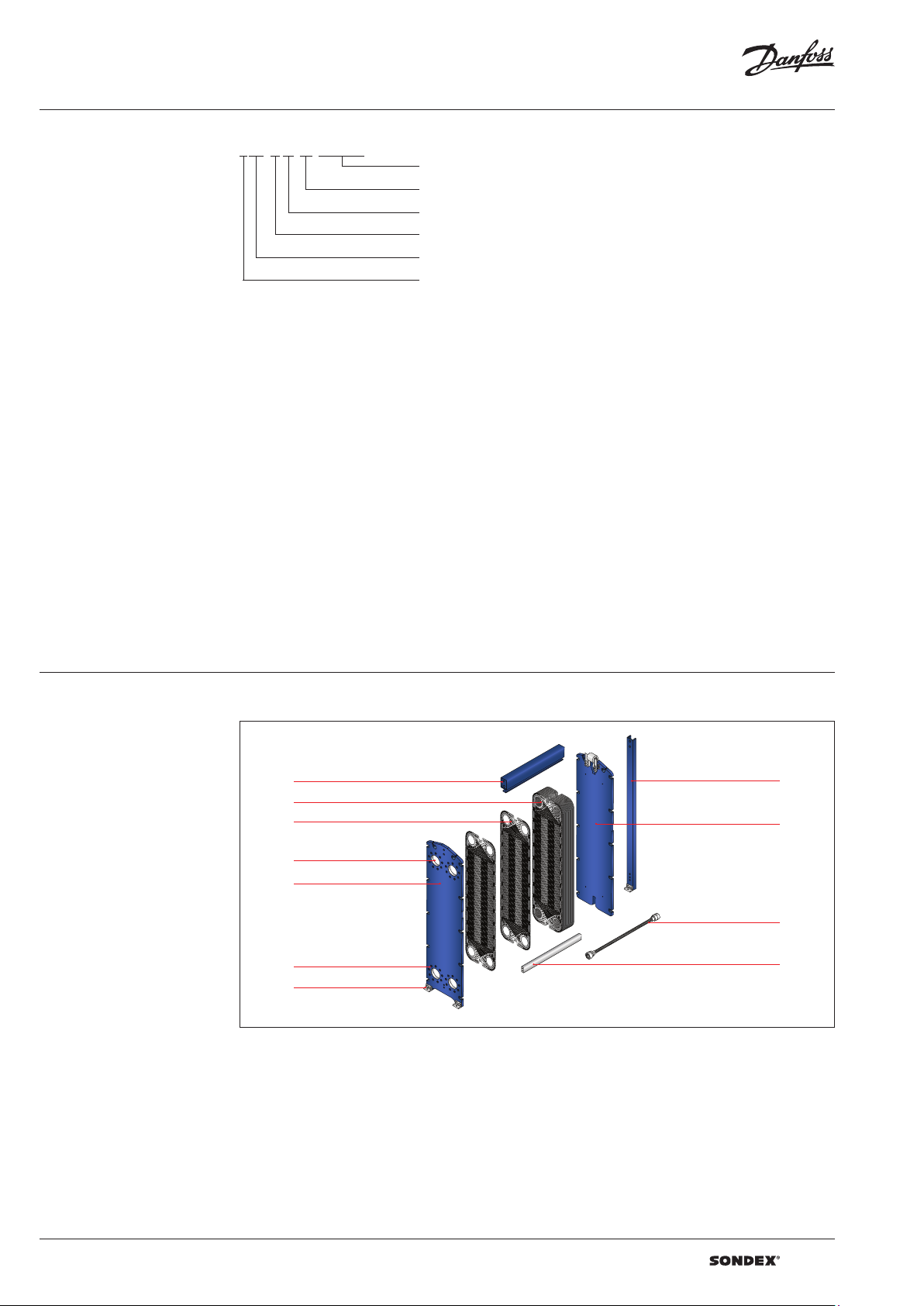
Heat exchanger design
Gasketed heat exchangers consist of
Carrying Bar
Plate Pack
Plate
Connections
Head
Flange Connections
Foundation Feet
Column
Follower
Tie Bolt
Guiding Bar
Anatomy of a SONDEX® plate heat exchanger - IS frame.
2 | VD.JQ.S1.02 | 2019.07
Page 3
Data sheet S67 / S113 / S155 (DN 250)
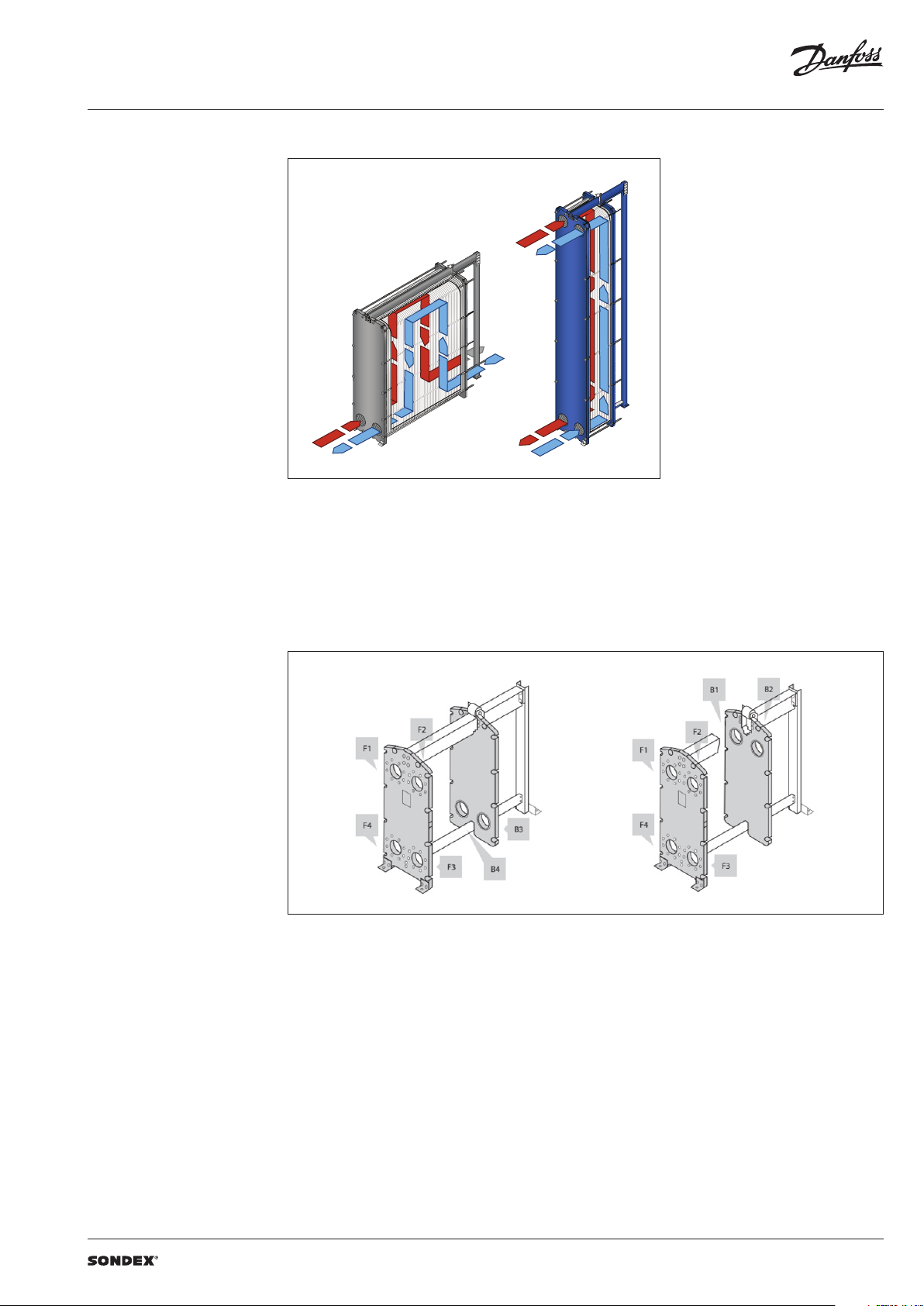
To the left: A multi-pass solution with connections
Heat exchanger design
(continued)
Multi-pass design
on the follower and the head.
To the right: A single-pass solution with
all connections on the head.
Connections
The heat exchanger may have connections on
both front and back-end sides of the unit.
Connections on the front-end plate are marked
with F and connections on the back-end plate
are marked with B. The numbers 1, 2, 3 and 4
designate the position of the connection on the
end-plate from the top-left port clockwise.
VD.JQ.S1.02 | 3 | 2019.07
Page 4

Data sheet S67 / S113 / S155 (DN 250)
SONDEX®
plate
range
Common
Technical data Heat exchanger S67 / S113 / S155
Typ e S67 S113 S155
Max. working pressure
Max. operating temperature
Min. operating temperature -10
Flow medium Water and different fluids, steam
Volume / channel l 1.8 3.6 4.7
Connection size DN 250 / 10”
Connection type
Plate material
Plate thickness mm
Gasket material
Gasket attachment t ype Sonder Lock
Liners in connections
Frame
Frame painting specification Painting available for corrosion categories C2L, C4M, C5M
1)
Not available f or all frame variations
2)
SonderSaf e - double plate
PN
(bar)
°C
(10)1), 16, 25
Up to 180
• DN 250/10” flanges. Carbon steel, rubberlined or cladded with AISI 316L
(other materials available on request)
Stainless steel EN 1.440 4 (AISI 316L), EN 1.4301 (AISI 304), SMO254, Hastelloy C276,
titanium Gr.1
Other materials available on request
0.4; 0.5; 0.6
2 x 0.4 SonderSafe plates
Other thicknesses available on request
NBR, EPDM,
Other materials available on request
• Rubber NBR, EPDM,
• Stainless steel EN 1.440 4 (AISI 316L), EN 1.4301 (AISI 304), SMO254, Hastelloy C276,
titanium Gr.1
• Painted frame, color RAL 5010 (other colors available on request)
• Stainless steel frame, designed for the sanitary applications (e.g. food and dairy
industries)
2)
Using the right plate for each individual duty
is very important, as it greatly impacts the
efficiency of the entire installation.
It is important that the length of the plates and
the type of pattern match the requirements of
individual thermal duty.
We have developed a wide plate portfolio to
provide the perfect plate and connection size for
any duty.
No application is too small or too big for us - we
provide the optimal technical solution every
time.
Our extensive SONDEX® plate portfolio
includes plates that lie outside the commonly
manufactured plate sizes to cover all thermal
duties optimally.
plate
range
4 | VD.JQ.S1.02 | 2019.07
Page 5

Data sheet S67 / S113 / S155 (DN 250)
Accessories Insulation
Recommended applications:
The insulation jacket for the plate heat exchanger
is used in different applications with high
temperatures and cooling systems.
Application Heating Cooling
Material
Outer cap
Internal insulation 0.05 mm aluminium foil
Panel fixation Plastic rivets
Temperature 20 … 200 °C -50 … -80 °C
U-value 0.55 W/m2K 0.3 8 W/m2K
Insulation class 3
Heat loss 17.1 W/m
Please note:
Inlet and outl et temperatures in the exch anger have been based on 9 0/50 – 3 0/70 °C.
1)
The loss of he ating/cooling is stated per m2 surface on the insu lation jacket.
The bottom o f the heat exchanger is not insu lated and this fact has been e xcluded.
A possible loss of ve ntilation, largely dep endent on the mounting of the h eat exchanger, has not been take n into account either.
Drip trays
Recommended applications:
The drip tray is available in two types. A “failsafe” solution which prevents water or liquid
from leaking onto the floor, or when the
heat exchanger is dismantled, or opened for
inspection and maintenance. And an insulated
drip tray for cooling applications, which
collects condensate formed outside of the plate
heat exchanger.
45 mm mineral wool
Not flammable
DIN EN 4102A2
1)
2
40 mm PU-foam
DIN 4102-1 B2
1 mm aluminium
“Stucco” Embossed
1)
4
-
Materials
Drip tray consists of:
• 1 mm galvanized steel frame
• Hanging brackets in galvanized steel
• 60 mm Polyurethane insulation for cooling
applications
• Draining valve.
Spare parts
Spare parts for gasketed heat exchangers, such
as plates, gaskets, frame parts can be ordered for
maintenance, repair, increasing heat exchanger
capacity, etc.
Selection and ordering Please contact your local SONDEX® or Danfoss
sales representative for the selection and / or
ordering of the heat exchangers, spare parts, and
accessories.
Please contact your local Danfoss or SONDEX®
sales representative to provide you with
information on spare parts available for gasketed
heat exchangers.
For contact information please visit
https://www.danfoss.com/en/contact-us.
VD.JQ.S1.02 | 5 | 2019.07
Page 6

Data sheet S67 / S113 / S155 (DN 250)
Dimensions
Non-sanitary applications
Any connection can be used for primary side in.
All the rest are made correspondingly.
S67 frames
448
329,5
F1
860,5
F4
362,5
F2
F3
7
W L
20
Ø18
140
Ø100
60
L + 150
L + 80
L1
B1B2
H
1552 ,5
B3
B4
14
70
10050
Ø25
50
W
740
Drawing of S67 IS16 frame
Number of plates
L (frame length)
1)
(mm)
W
(mm)
H
(mm)
Weight max, empt y
(kg)
2)
Connection type
S67 I S16
8 80 1077
81 134 1377 2117
135 170 1577 2279
171 261 2077 2693
262 352 2720
890
35.04”
353 443 3220 3550
444 625 4220 4467
1)
the indicate d maximum number of pla tes is based on the minimum plate thi ckness allowable for the PN le vel of the unit;
2)
the maximum w eight of the empty unit with t he maximum allowable nu mber of plates;
*)
PN class 10 bar / 25 bar is ava ilable on request.
1652,5
(65.06”)
1705. 5
(6 7.15“ )
1879
DN 250 flange or 10”
3120
flange
6 | VD.JQ.S1.02 | 2019.07
Page 7

Data sheet S67 / S113 / S155 (DN 250)
Dimensions (continued)
Non-sanitary applications
S113 frames
329,5362,5
F1
448
1527
F4
Drawing of S113 IS16 frame
L1
B1
F2
H
F3
7
L
L + 80
140
2219
14
5020
W
705
B2
1527 329,5362,5
B3
B4
Ø18
Ø25
Number of plates
L (frame length)
1)
(mm)
W
(mm)
H
(mm)
Weight max, empt y
(kg)
2)
Connection type
S113 IS16
9 80 1097
81 135 1397 3017
136 171 1597 3266
172 262 2097 3895
263 353 274 0
855
33.66”
354 444 3240 5153
445 626 4240 6412
2319
(91.3 0”)
2372
(93.39 “)
2636
DN 250 flange or 10”
4525
S113 IS2 5
9 80 1097
81 133 1397 3150
134 169 1597 3439
170 258 2097 4154
259 343 274 0
920
36.22”
344 433 3240 5562
434 611 4240 6992
1)
the indicate d maximum number of pla tes is based on the minimum plate thi ckness allowable for the PN le vel of the unit;
2)
the maximum w eight of the empty unit with t he maximum allowable nu mber of plates;
*)
PN class 10 bar is avail able on request.
2319
91.30”
2372
93.39“
2724
DN 250 flange or 10”
48 41
flange
flange
VD.JQ.S1.02 | 7 | 2019.07
Page 8

Data sheet S67 / S113 / S155 (DN 250)
Dimensions (continued)
Non-sanitary applications
S155 frames
F1
F4
448
W
Ø100
L1
339,5
B1
F2
2054
F3
2801
150
362,5
20
60
L
14
70
100
B2
H
B4
B3
L + 125
100
L - 25
50
Ø25
200
160
740
200
Ø25
Drawing of S155 IS16 frame
Number of plates
L (frame length)
1)
(mm)
W
(mm)
H
(mm)
Weight max, empt y
(kg)
2)
Connection type
S155 IS16
7 34 820
3345
35 107 122 0 3965
108 161 15 20 4425
162 19 8 172 0 4739
199 289 2220 5513
890
35.04”
2901
(114 .2 1”)
DN 250 flange or 10”
290 380 2720 6286
381 470 3220 7052
471 652 4220 8600
S155 IS25
7 28 840
4219
29 100 1240 4936
101 153 154 0 5465
154 189 1740 5823
190 278 2240 6709
920
(36.22”)
2901
(114 .2 1”)
DN 250 flange or 10”
279 367 274 0 7596
368 457 3240 8492
458 635 4240 10267
1)
the indicate d maximum number of pla tes is based on the minimum plate thi ckness allowable for the PN le vel of the unit;
2)
the maximum w eight of the empty unit with t he maximum allowable nu mber of plates;
*)
PN class 10 bar is avail able on request.
flange
flange
| DHS-SRMT/SI | 2019.078 | VD.JQ.S1.02
 Loading...