

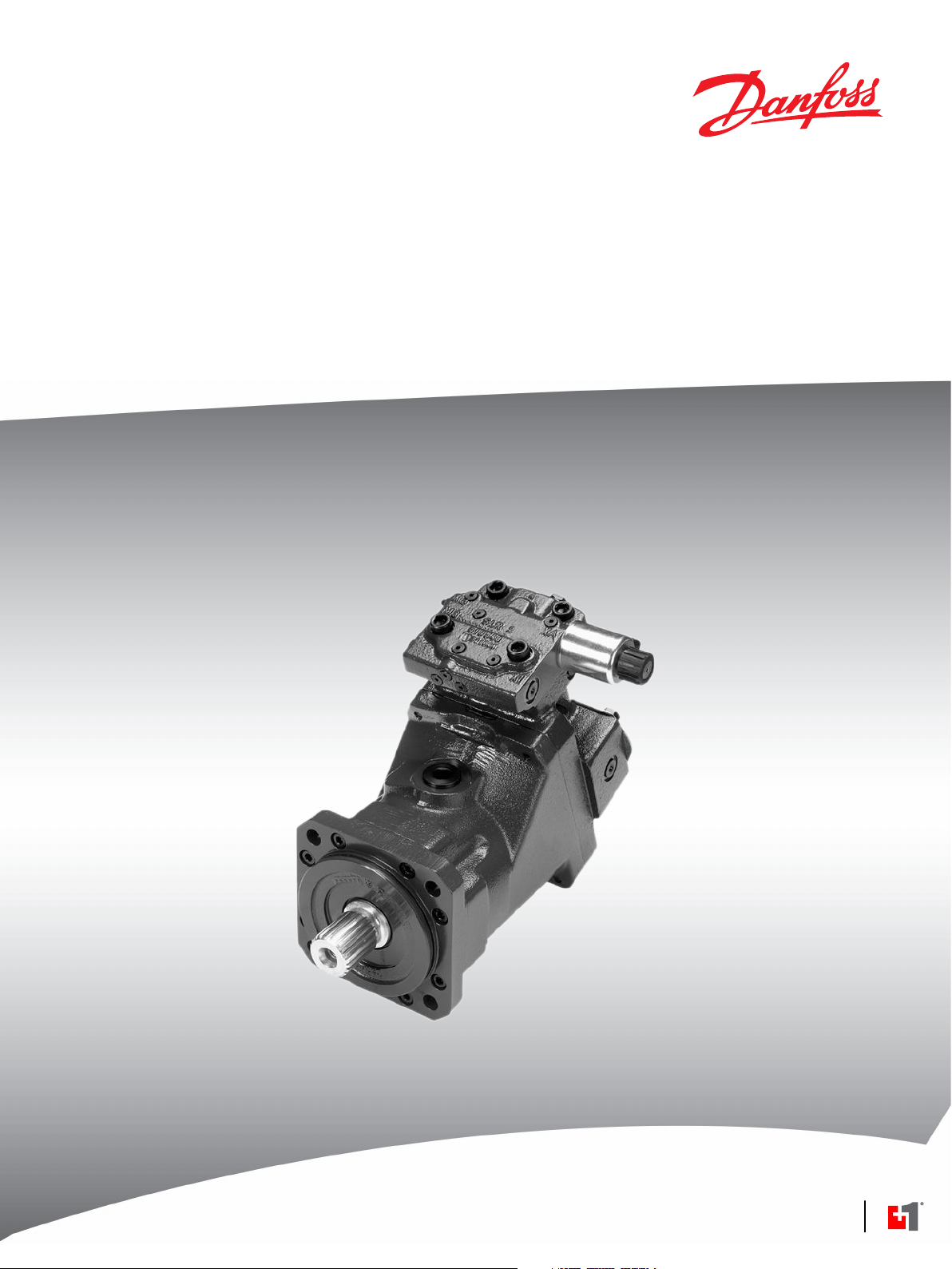
Page 1
MAKING MODERN LIVING POSSIBLE
Electrical Installation
Series 51-1 Motor
Hydraulic Two-Position Controls
TH
powersolutions.danfoss.com
Page 2

Electrical Installation S51-1 Hydraulic Two-Position Controls TH
Revision history Table of revisions
Date Changed Rev
August 2015 Converted to Danfoss layout BA
April 2007 First edition AA
2 11024929 • Rev BA • August 2015
Page 3

Electrical Installation
Contents
Literature references
Product overview
Electrical installation
S51-1 Hydraulic Two-Position Controls TH
S51-1 Hydraultic Two-Position Controls TH literature references.................................................................................. 4
Latest version of technical literature.........................................................................................................................................4
Product image................................................................................................................................................................................... 5
Nomenclature....................................................................................................................................................................................5
Theory of operation.........................................................................................................................................................................6
TH**..................................................................................................................................................................................................6
PCOR................................................................................................................................................................................................ 6
THCA................................................................................................................................................................................................ 6
THD1, THD2, THD7......................................................................................................................................................................6
Control operation TH**.............................................................................................................................................................6
Hydraulic schematics...................................................................................................................................................................... 7
Electrical specifications.................................................................................................................................................................. 7
Pinout....................................................................................................................................................................................................8
DIN 43650 connector.................................................................................................................................................................8
AMP Junior Power Timer connector.....................................................................................................................................8
Pin compatibility...............................................................................................................................................................................8
Pressure compensator logic......................................................................................................................................................... 9
Hydraulic brake pressure defeat............................................................................................................................................9
Electric brake pressure defeat................................................................................................................................................ 9
Mating connector.............................................................................................................................................................................9
DIN 43650 connector parts list...............................................................................................................................................9
AMP connector parts list.......................................................................................................................................................... 9
11024929 • Rev BA • August 2015 3
Page 4

Electrical Installation S51-1 Hydraulic Two-Position Controls TH
Literature references
S51-1 Hydraultic Two-Position Controls TH literature references
Literature title Description Literature number
S51 and 51-1 Bent Axis Variable Displacement Motors
Technical Information
On/Off Functions Function Block User Manual Compliant function block
Latest version of technical literature
Danfoss product literature is online at: http://powersolutions.danfoss.com/literature/
Complete product electrical
and mechanical
specifications
set-up information
520L0440
11022918
4 11024929 • Rev BA • August 2015
Page 5
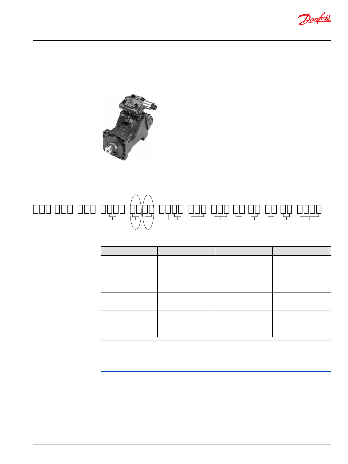
5 1
R G L F M N J S T W Y P K V Z X
Electrical Installation
Product overview
Product image
Nomenclature
S51-1 model code
S51-1 Hydraulic Two-Position Controls TH
S51-1 Hydraultic Two-Position Controls TH
Code M and N options
M Description N Description
TH Hydraulic two-position
control
D1 Electric brake pressure
defeat, 12 Vdc, DIN
Connector
D2 Electric brake pressure
defeat, 24 V,dc DIN
Connector
D7 Electric brake pressure
defeat, 12 Vdc, AMP
Connector
CA With hydraulic brake
pressure defeat
C2 Without brake pressure
defeat
Only certain control options for the S51-1 motor utilize the Hydraulic Two-Position Control. The
combination of the M and N modules define the motor control’s functionality. Please refer to the motor’s
nomenclature to determine if the motor is equipped with the proper option. The nomenclature can be
found on the motor’s nametag.
11024929 • Rev BA • August 2015 5
Page 6
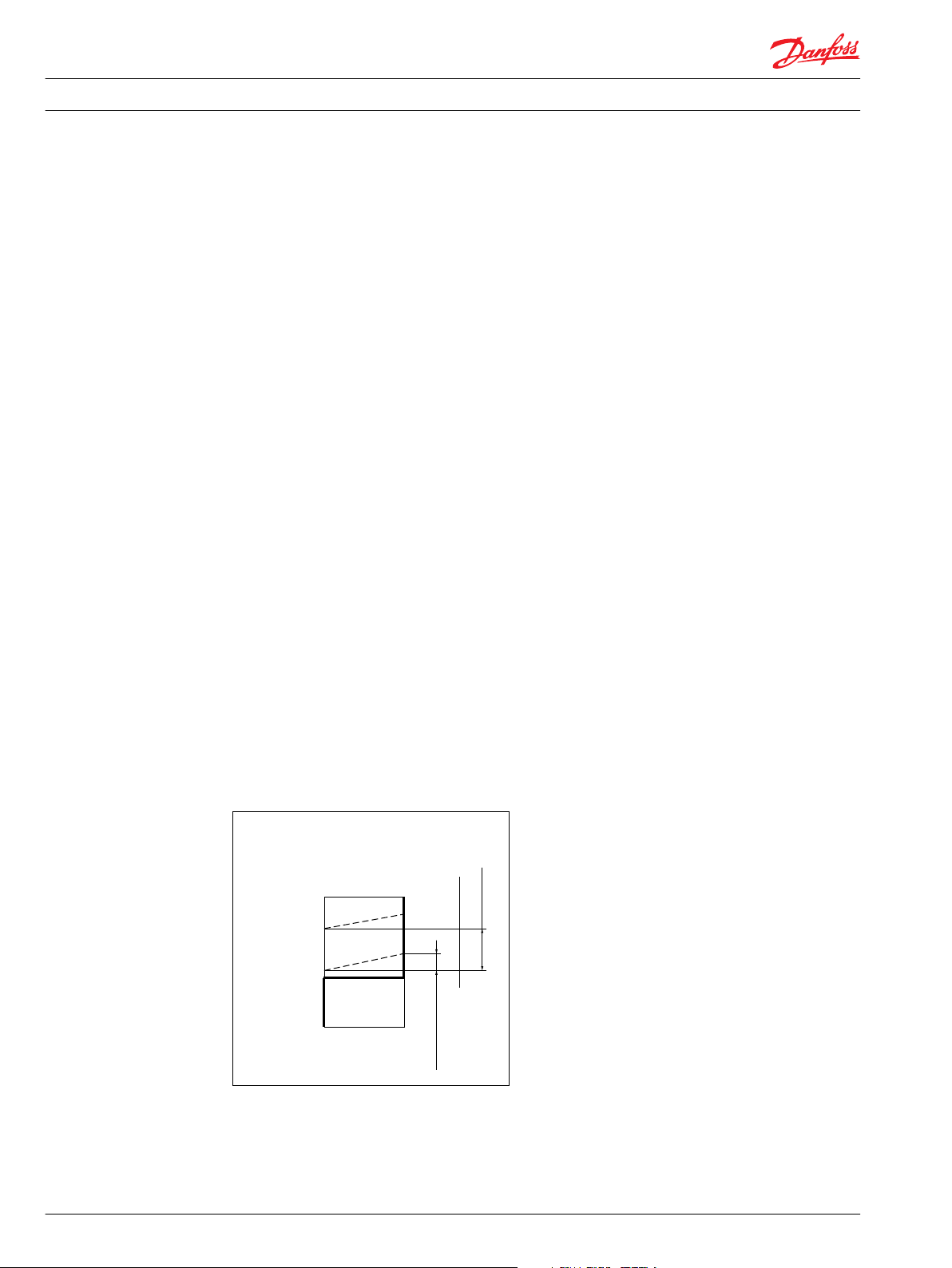
min.
[145 psi]
min. 10 bar
[510 psi]
max. 35 bar
max.
Displacement
Hydraulic
two-positioncontrol
PCOR start
setting range
Ramp < 10
[145]
130
[1890]
370 [5370]
Pressure compensator
override bar, [psi]
P001 776E
Electrical Installation
Product overview
Theory of operation
S51-1 Hydraulic Two-Position Controls TH
TH**
Displacement can be changed hydraulically under load from minimum displacement to maximum
displacement and vice versa. Pressure on port X1 must be equal to the pressure of the motor case ± 0.2
bar, [3.0 psi] this keeps the motor at minimum displacement. Pressure 10 bar, [145 psi] to 35 bar, [510 psi]
above case pressure on port X1 strokes the motor to maximum displacement.
PCOR
The control can be overridden by Pressure Compensator Override (PCOR) using high loop pressure. When
the PCOR activates, the motor displacement increases toward maximum. Pressure ramp from PCOR start
pressure (with motor at minimum displacement) until maximum displacement is reached is less than 10
bar [145 psi]. This ensures optimal power utilization throughout the entire displacement range of the
motor. PCOR start pressure is adjustable from 110 to 370 bar [1600 to 5370 psi].
THCA
Pressure compensator configuration: THCA with hydraulic brake pressure defeat.
A shuttle valve ahead of the pressure compensator prevents operation in the deceleration direction
(when motor is running in pump mode). This is designed to prevent rapid or uncontrolled deceleration
while the vehicle/machine is slowing down. The shuttle valve must be controlled by a 2-line external
signal. Pressure compensator override with brake pressure defeat is mainly used in systems with pumps
having electric or hydraulic proportional controls or automotive controls.
THD1, THD2, THD7
Pressure compensator configuration: THD1, THD2, THD7 with electric brake pressure defeat.
A solenoid-switched valve ahead of the pressure compensator prevents operation in the deceleration
direction (when motor is running in pump mode). This is designed to prevent rapid or uncontrolled
deceleration while the vehicle/machine is slowing down. The solenoid valve must be controlled by an
external electric signal.
Control operation TH**
6 11024929 • Rev BA • August 2015
Page 7
W
n
min.
disp.
B
M4
L1
N
L2
A
P001 835E
T3
M3
X1
T3
M3
XB
XA
X1
T3
M3
X1
with Electric
brake pressure
defeat
with Hydraulic
brake pressure
defeat
without
Brake pressure
defeat
Electrical Installation S51-1 Hydraulic Two-Position Controls TH
Product overview
Warning
Unintended vehicle or machine movement hazard. The loss of hydrostatic drive line power, in any mode
of operation (forward, neutral, or reverse) may cause the system to lose hydrostatic braking capacity. You
must provide a braking system, redundant to the hydrostatic transmission, sufficient to stop and hold the
vehicle or machine in the event of hydrostatic drive power loss.
Hydraulic schematics
Circuit diagram – motor with two-position control TH**
Electrical specifications
Ports:
Electric brake pressure defeat solenoid
N-option
Voltage
Rated power
11024929 • Rev BA • August 2015 7
A, B = Main pressure lines
L1, L2 = Drain lines
M1, M2 = Gauge port for A and B
M3, M4 = Gauge port servo pressure
M5 (X3) = Gauge port servo supply
XA, XB = Control pressure ports, brake pressure defeat
X1 = Hydraulic two-position signal
X4 = Gauge port pressure compensator
T1, T2, T3, T7, T8 = Optional orifices
N = Speed sensor
D1, D7 D2
12 Vdc 24 Vdc
34 W 34 W
Page 8
1 2
2 1
Electrical Installation S51-1 Hydraulic Two-Position Controls TH
Electrical installation
Pinout
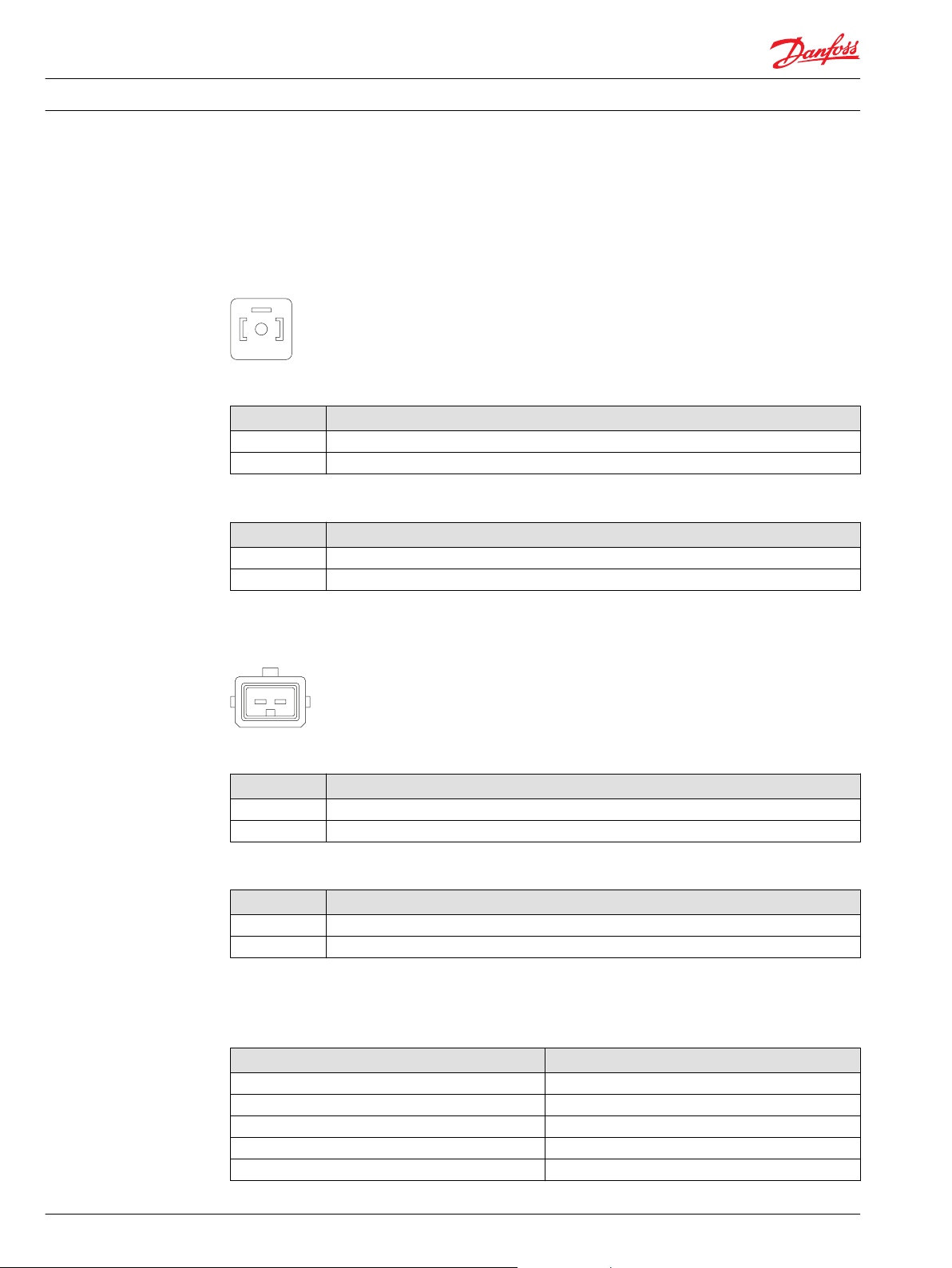
DIN 43650 connector
Pin location
Pinout
Pin Function
1 PWM signal
2 Ground
Pinout (alternative)
Pin Function
1 Ground
2 PWM signal
Pin compatibility
AMP Junior Power Timer connector
Pin location
Pinout
Pin Function
1 PWM signal
2 Ground
Pinout (alternative)
Pin Function
1 Ground
2 PWM signal
PLUS+1® module pin type
Pin Function
1,2 DOUT
1,2 DOUT/PVG Power
1,2 PWMOUT/DOUT/PVG Power supply
1,2 PWMOUT/DOUT/PVGOUT
1,2 Power ground -
8 11024929 • Rev BA • August 2015
Page 9

Electrical Installation S51-1 Hydraulic Two-Position Controls TH
Electrical installation
Pressure compensator logic
Hydraulic brake pressure defeat
Motor rotation High pressure port Control pressure on port*PCOR function
CW A XA yes
CW A XB no
CCW B XA no
CCW B XB yes
*
Differencial control pressure between port XA/XB:
∆p
= 0.5 bar [7 psi]
min
∆p
= 50 bar [725 psi]
max
Electric brake pressure defeat
Motor rotation High pressure port Solenoid PCOR function
CW A energized yes
CW A non energized no
CCW B energized no
CCW B non energized yes
Mating connector
DIN 43650 connector parts list
Description Quantity Ordering Number
DIN 43650 connector 1 Hirschmann 932 106-100
Mating connector kit 1 Danfoss K09129
AMP connector parts list
Description Quantity Ordering number
Two pin connector 1 Tyco Electronics 282189-1
Contacts 2 Tyco Electronics 929940-1
Seal plugs 2 Tyco Electronics 828904-1
Mating connector kit 1 Danfoss K19815
11024929 • Rev BA • August 2015 9
Page 10

Electrical Installation S51-1 Hydraulic Two-Position Controls TH
10 11024929 • Rev BA • August 2015
Page 11

Electrical Installation S51-1 Hydraulic Two-Position Controls TH
11024929 • Rev BA • August 2015 11
Page 12

Danfoss
Power Solutions GmbH & Co. OHG
Krokamp 35
D-24539 Neumünster, Germany
Phone: +49 4321 871 0
Danfoss
Power Solutions ApS
Nordborgvej 81
DK-6430 Nordborg, Denmark
Phone: +45 7488 2222
Danfoss
Power Solutions (US) Company
2800 East 13th Street
Ames, IA 50010, USA
Phone: +1 515 239 6000
Danfoss
Power Solutions Trading
(Shanghai) Co., Ltd.
Building #22, No. 1000 Jin Hai Rd
Jin Qiao, Pudong New District
Shanghai, China 201206
Phone: +86 21 3418 5200
Products we offer:
Comatrol
www.comatrol.com
Schwarzmüller-Inverter
www.schwarzmuellerinverter.com
Turolla
www.turollaocg.com
Hydro-Gear
www.hydro-gear.com
Daikin-Sauer-Danfoss
www.daikin-sauer-danfoss.com
Bent Axis Motors
•
Closed Circuit Axial Piston
•
Pumps and Motors
Displays
•
Electrohydraulic Power
•
Steering
Electrohydraulics
•
Hydraulic Power Steering
•
Integrated Systems
•
Joysticks and Control
•
Handles
Microcontrollers and
•
Software
Open Circuit Axial Piston
•
Pumps
Orbital Motors
•
PLUS+1® GUIDE
•
Proportional Valves
•
Sensors
•
Steering
•
Transit Mixer Drives
•
Danfoss Power Solutions is a global manufacturer and supplier of high-quality hydraulic and
electronic components. We specialize in providing state-of-the-art technology and solutions
that excel in the harsh operating conditions of the mobile off-highway market. Building on
our extensive applications expertise, we work closely with our customers to ensure
exceptional performance for a broad range of off-highway vehicles.
We help OEMs around the world speed up system development, reduce costs and bring
vehicles to market faster.
Danfoss – Your Strongest Partner in Mobile Hydraulics.
Go to www.powersolutions.danfoss.com for further product information.
Wherever off-highway vehicles are at work, so is Danfoss. We offer expert worldwide support
for our customers, ensuring the best possible solutions for outstanding performance. And
with an extensive network of Global Service Partners, we also provide comprehensive global
service for all of our components.
Please contact the Danfoss Power Solution representative nearest you.
Danfoss can accept no responsibility for possible errors in catalogues, brochures and other printed material. Danfoss reserves the right to alter its products without notice. This also applies to
products already on order provided that such alterations can be made without changes being necessary in specifications already agreed.
All trademarks in this material are property of the respective companies. Danfoss and the Danfoss logotype are trademarks of Danfoss A/S. All rights reserved.
11024929 • Rev BA • August 2015 www.danfoss.com
Local address:
©
Danfoss A/S, 2015
 Loading...