

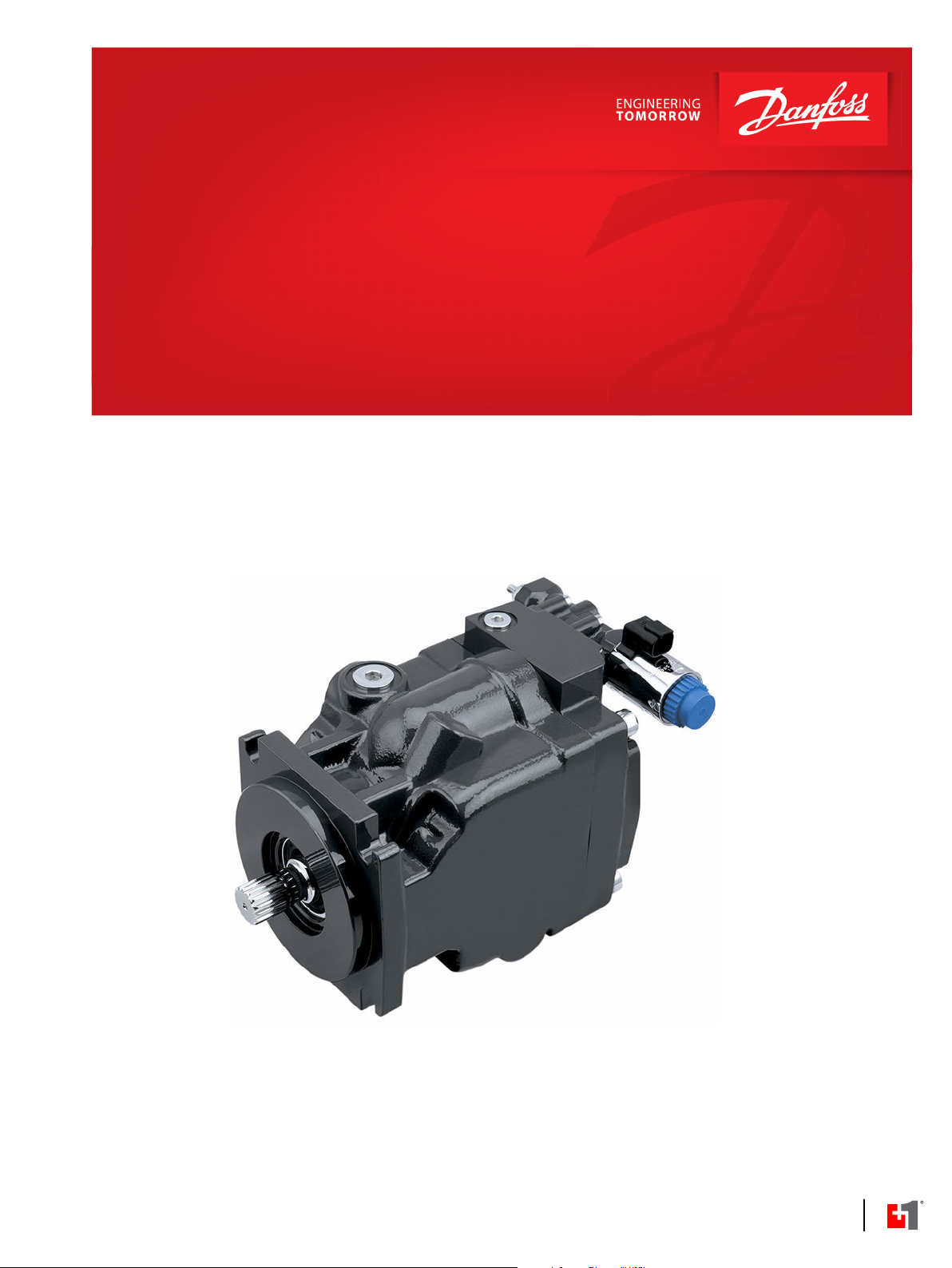
Electrical Installation
Series 45 Pumps
Fan Drive Control (FDC)
powersolutions.danfoss.com

Electrical Installation
S45 FDC
Revision history Table of revisions
Date Changed Rev
July 2016 First edition 0101
2 | © Danfoss | July 2016 BC00000371en-US0101

Electrical Installation
S45 FDC
Contents
Literature references
Product overview
Electrical installation
Literature references....................................................................................................................................................................... 4
Latest version of technical literature.........................................................................................................................................4
Product image................................................................................................................................................................................... 5
Order code.......................................................................................................................................................................................... 5
Fan Drive Control configuration................................................................................................................................................. 5
NC Fan Drive Control 3D Views................................................................................................................................................... 6
Fan Drive Control Principle ..........................................................................................................................................................6
Fan Drive Control System Characteristics................................................................................................................................7
Unintended Applications for Fan Drive Control Systems..................................................................................................7
Fan Drive Control characteristic - Normally Closed ............................................................................................................ 7
Solenoid data – Normally closed................................................................................................................................................ 8
Connectors..........................................................................................................................................................................................9
Pinout....................................................................................................................................................................................................9
©
Danfoss | July 2016 BC00000371en-US0101 | 3

Electrical Installation
S45 FDC
Literature references
Literature references
Literature title Description Literature number
S45 Axial Piston Open Circuit Pumps Technical Information Complete product electrical
S45 Pump Fan Drive Control Function Block User Manual Compliant function block
Latest version of technical literature
Danfoss product literature is online at: http://powersolutions.danfoss.com/literature/
and mechanical
520L0519
specifications
BC00000369
set-up information
4 | © Danfoss | July 2016 BC00000371en-US0101

SR P JC D E F G H
K
L M N
Electrical Installation
S45 FDC
Product overview
Product image
Order code
S45 Fan Drive Control
S45 Pump model code
Fan Drive Control configuration
The available Normally Closed Fan Drive Controls for Series 45 are shown below. The allowable Pressure
Compensator (PC) pressure settings are provided for each frame.
C module—Control
G module options—Choke Orifice
Fan Drive Control Options Frame
Code Description L K J F E
SA Pressure Compensation (12Vdc), 100-210 Bar, Left • •
SB Pressure Compensation (24Vdc), 100-210 Bar, Left • •
SC Pressure Compensation (12Vdc), 220-310 Bar, Left • •
SD Pressure Compensation (24Vdc), 220-310 Bar, Left • •
SE Pressure Compensation (12Vdc), 100-210 Bar, Right • •
SF Pressure Compensation (24Vdc), 100-210 Bar, Right • •
SG Pressure Compensation (12Vdc), 220-310 Bar, Right • •
SH Pressure Compensation (24Vdc), 220-310 Bar, Right • •
Fan Drive Control options Choke Orifice size
G 0.8 mm (0.031 in)
F 1.0 mm (0.039 in
H module options—Gain Orifice
Fan Drive Control options Gain Orifice Size
E 1.2 mm (0.047 in)
©
Danfoss | July 2016 BC00000371en-US0101 | 5

W
Electrical Installation
S45 FDC
Product overview
NC Fan Drive Control 3D Views
Fan Drive Control Principle
Left Right
The Fan Drive Control is a unique electrically actuated pressure control solution that consists of a
normally closed proportional solenoid and one dual diameter spool sliding in the control housing.
System pressure acts on an area between the two spool diameters of the spool lands. This hydraulic force
is balanced with forces of springs and the solenoid when the spool is in the metering position. When no
current is sent to the solenoid it operates the pump at or below the PC setting which is adjusted
mechanically with the adjustor screw and lock nut. Increasing the control current proportionally reduces
the pump's outlet pressure until a minimum standby pressure is reached.
Control Block 12V and 24V
The minimum system pressure is given by swashplate moments of the pump and by servo system
leakages which produce a pressure drop across the control. In addition, fan motor type and fan inertia
impact minimum system pressure.
The Normally Closed Fan Drive Control coupled with a microprocessor allows the pump to operate at an
infinite range of operating pressures between a minimum system pressure and PC setting.
We recommend that a relief valve be installed in the pump outlet for additional system protection.
Warning
The Fan Drive Control is intended for fan drive systems only! Use in other systems could result in system
component damage or unintended machine movement. The Fan Drive Control is not intended to serve
at the primary system pressure relief. Loss of the input signal to this control will cause the pump to
produce maximum flow.
6 | © Danfoss | July 2016 BC00000371en-US0101

M2
L2
S
L1
P109019
B
Legend
B
S
L1, L2
M2
= Outlet
= Inlet
= Case drain
= System pressure
gauge port
Gain
Orifice
Choke
Orifice
Electrical Installation
S45 FDC
Product overview
Fan Drive Control System Characteristics
•
Constant pressure and variable flow
•
High or low system pressure mode based on fan cooling demand
•
System flow adjusts to meet system requirements
Unintended Applications for Fan Drive Control Systems
•
Applications with frequent PC events (system pressure overshoots)
•
Adjustable Load Sensing systems
Fan Drive Control Cross Section
Fan Drive Control characteristic - Normally Closed
When an electric current is sent to the Normally Fan Drive Control, pump outlet pressure decreases
proportionally to the increase in currentt. When the load in the system changes, the pump will adjust its
displacement to maintain the pressure demanded by the controlling current. This predictable control is
especially useful for fan-drive systems, due to the direct relationship between fan-speed and pump
pressure. Due to the nature of the Fan Drive Control, the relationship between current and pump
pressure is unique for each individual PC pressure setting combination. The relationship between pump
outlet pressure and control input current (for a 24V coil) is shown for various PC settings below. The
hydraulic schematic for the Normally Closed Fan Drive Control is shown below as well.
Attaining remarkably low system pressures is possible with the Fan Drive Control. The minimum system
pressure is greatly dependent on individual system parameters such as fan motor type and fan size. This
feature is highly desirable in low cooling demand conditions to keep fan speed as slow as possible.
Virtually eliminated control deadband increases controllability and reduces power loss. Control current
resolution is greatly improved.
S45 pump with integrated FDC control Schematic
©
Danfoss | July 2016 BC00000371en-US0101 | 7

Electrical Installation
S45 FDC
Product overview
Solenoid data – Normally closed
Solenoid Data – Normally Closed
Connector on solenoid Deutsch DT04-2P
Mating Connector (not included) Deutsch DT06-2S
Identification by color of nut Black Blue
Nominal current 1650 mA 840 mA
Maximum Control Current 1800 mA 920 mA
Environmental rating IP67 without mating connector,
Maximum output driver current 2.0 Amps
PLUS+1 dither frequency Not recommended
Useable PWM Frequency Range 50-200 Hz
Recommended PWM Frequency 200 Hz
Nominal Resistance at 20°C 3.66 Ω 14.2 Ω
Inductivity (pin at stroke end) 33 mH 140 mH
Minimum voltage 9.5 Vdc 19.0 Vdc
Maximum power 17.9 Watts 18.1 Watts
12V 24V
IP69K with mating connector
The Fan Drive Control is designed as a current driven control. It requires a PWM- input signal.
8 | © Danfoss | July 2016 BC00000371en-US0101

1 2
P003480
Electrical Installation
S45 FDC
Electrical installation
Connectors
Pinout
Description Quantity Ordering Number
Mating Connector 1 Deutsch® DT06-2S
Wedge Lock 1 Deutsch® W25
Socket Contact (16 and 18 AWG) 2 Deutsch® 0462-201-16141
Danfoss mating connector kit 1 K29657
Pin location
Pin Function
1 Power ground- or PWMOUT
2 PWMOUT or Power ground-
©
Danfoss | July 2016 BC00000371en-US0101 | 9

Electrical Installation
S45 FDC
10 | © Danfoss | July 2016 BC00000371en-US0101

Electrical Installation
S45 FDC
©
Danfoss | July 2016 BC00000371en-US0101 | 11

Danfoss
Power Solutions GmbH & Co. OHG
Krokamp 35
D-24539 Neumünster, Germany
Phone: +49 4321 871 0
Danfoss
Power Solutions ApS
Nordborgvej 81
DK-6430 Nordborg, Denmark
Phone: +45 7488 2222
Danfoss
Power Solutions (US) Company
2800 East 13th Street
Ames, IA 50010, USA
Phone: +1 515 239 6000
Danfoss
Power Solutions Trading
(Shanghai) Co., Ltd.
Building #22, No. 1000 Jin Hai Rd
Jin Qiao, Pudong New District
Shanghai, China 201206
Phone: +86 21 3418 5200
Products we offer:
Comatrol
www.comatrol.com
Schwarzmüller-Inverter
www.schwarzmuellerinverter.com
Turolla
www.turollaocg.com
Hydro-Gear
www.hydro-gear.com
Daikin-Sauer-Danfoss
www.daikin-sauer-danfoss.com
Bent Axis Motors
•
Closed Circuit Axial Piston
•
Pumps and Motors
Displays
•
Electrohydraulic Power
•
Steering
Electrohydraulics
•
Hydraulic Power Steering
•
Integrated Systems
•
Joysticks and Control
•
Handles
Microcontrollers and
•
Software
Open Circuit Axial Piston
•
Pumps
Orbital Motors
•
PLUS+1® GUIDE
•
Proportional Valves
•
Sensors
•
Steering
•
Transit Mixer Drives
•
Danfoss Power Solutions is a global manufacturer and supplier of high-quality hydraulic and
electronic components. We specialize in providing state-of-the-art technology and solutions
that excel in the harsh operating conditions of the mobile off-highway market. Building on
our extensive applications expertise, we work closely with our customers to ensure
exceptional performance for a broad range of off-highway vehicles.
We help OEMs around the world speed up system development, reduce costs and bring
vehicles to market faster.
Danfoss – Your Strongest Partner in Mobile Hydraulics.
Go to www.powersolutions.danfoss.com for further product information.
Wherever off-highway vehicles are at work, so is Danfoss. We offer expert worldwide support
for our customers, ensuring the best possible solutions for outstanding performance. And
with an extensive network of Global Service Partners, we also provide comprehensive global
service for all of our components.
Please contact the Danfoss Power Solution representative nearest you.
Local address:
Danfoss can accept no responsibility for possible errors in catalogues, brochures and other printed material. Danfoss reserves the right to alter its products without notice. This also applies to products
already on order provided that such alterations can be made without changes being necessary in specifications already agreed.
All trademarks in this material are property of the respective companies. Danfoss and the Danfoss logotype are trademarks of Danfoss A/S. All rights reserved.
©
Danfoss | July 2016 BC00000371en-US0101
 Loading...