

Page 1

Data sheet
Gasketed Plate Heat Exchangers (DN 200 / 8”)
S43 / S43AD / S65 / S100 / S100AD / S100TY / S130 / S131 / S152 / S221 / S229
Description
SONDEX® gasketed plate heat exchangers are
the ideal choice for a wide range of applications
across numerous market segments.
We have the largest plate portfolio in the
world, and we customize each heat exchanger
to meet your exact requirements. Innovative
technologies and smart design make our
gasketed plate heat exchangers a stellar
investment.
Benefits:
• Individually customized solution that
perfectly matches your requirements and
lowers your energy consumption.
• High performance and a low pressure
drop eliminate unnecessary burdens on
your system and optimize overall system
performance.
• The design results in a compact solution with
a small footprint, simple installation, and easy
access for maintenance.
Common applications:
• HVAC industry
• Marine/offshore industry
• Dairy/food/beverage industry
• Sugar industry
• Biogas industry
• Pulp and paper industry
• Heavy industry
• Mining industry
• Petrochemical industry
• Chemical industry DN 200
Main data:
• Min. temperature −10 °C
• Max. temperature 180 °C
• Max. working pressure 16 / 25 bar (6 / 10 bar
on request)
• Water and different fluids, steam
• Connection size DN 200 or 8”
Approvals:
• Please contact your local Danfoss/SONDEX®
sales representative for an overview of the
available approvals in your region
Construction standard:
• EN13445 (PED 2014/68/EU)
• ASME sec VIII, Div. 1
| 2019.07 VD.JQ.P1.02 | 1
Page 2

Data sheet S43 / S43AD / S65 / S100 / S100AD / S100TY / S130 / S131 / S152 / S221 / S229 (DN 200 / 8”)
Naming of units
S43-IS16-21-TKTL89
3)
1)
1)
Type of heat exchanger:
TKTL89 - Plate grouping
21 - Number of plates in the heat exchanger
16 - Design pressure of the heat exchanger
IS - Frame type
2)
43 – Type of heat exchanger
S – Gasketed heat exchanger
43 - …
Letter A shows type of the attachment of gasket to plate:
e.g. 43 (without A) – SonderLock
43A (with A) – Hang-on
AD - wider channel gap design
TY - asymmetric channel design
2)
Description of frame types:
There are few different frame types which can be offered for different applications and duties.
IS – with suspension roller,
IG – without suspension roller,
FS – food/sanitary with suspension roller,
FG - food/sanitary,
ST – simple design of frame with threaded connections
3)
Channel grouping:
In this example, the heat exchanger combines TK and TL channels. The share of TL channels equals
89% of the total number of channels.
The number of channels is defined as “the number of plates - 1”.
TK - short thermal length
TM - medium thermal length
TL - long thermal length
Heat exchanger design
Gasketed heat exchangers consist of
Carrying Bar
Plate Pack
Plate
Connections
Head
Flange Connections
Foundation Feet
Column
Follower
Tie Bolt
Guiding Bar
Anatomy of a SONDEX® plate heat exchanger - IS frame.
2 | VD.JQ.P1.02 | 2019.07
Page 3
Data sheet S43 / S43AD / S65 / S100 / S100AD / S100TY / S130 / S131 / S152 / S221 / S229 (DN 200 / 8”)
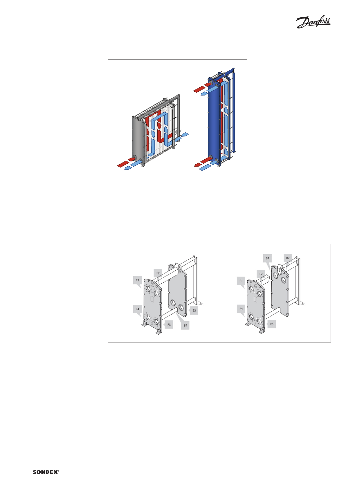
To the left: A multi-pass solution with connections
Heat exchanger design
(continued)
Multi-pass design
on the follower and the head.
To the right: A single-pass solution with
all connections on the head.
Connections
The heat exchanger may have connections on
both front and back end sides of the unit.
Connections on the front-end plate are marked
with F and connections on the back-end plate
are marked with B. The numbers 1, 2, 3 and 4
designate the position of the connection on the
end-plate from the top-left port clockwise.
VD.JQ.P1.02 | 3 | 2019.07
Page 4

Data sheet S43 / S43AD / S65 / S100 / S100AD / S100TY / S130 / S131 / S152 / S221 / S229 (DN 200 / 8”)
SONDEX®
plate
range
Common
Technical data
Heat exchanger S43 / S43AD / S65 / S100 / S100AD / S100TY / S130 / S131 / S152 / S221 / S229
Typ e
Max. working
pressure
Max. operating
temperature
Min. operating
temperature
Flow medium Water and different fluids, steam
Volume / channel l 1.3 2.6 1.7 2. 38 4.23 2.92 / 1.84 3.4 8.6 4.03 5.9 11. 0
Connection size DN 200/ 8"
Connection type
Plate material
Plate thickness mm
Gasket material
Gasket attachment t ype Hang-on; Sonder Lock
Liners in connections
Frame
Frame painting
specification
1)
Not available f or all frame variations
2)
SonderSaf e – double plate
S43 S43AD S65 S100 S100A D S100T Y S130 S131 S152 S221 S229
PN
(bar)
°C
• DN 200/8” flanges. Carbon steel, rubberlined or cladded with AISI 316L (other materials available
on request)
Stainless steel EN 1.440 4 (AISI 316L), EN 1.4301 (AISI 304), SMO254, Hastelloy C276, titanium Gr.1
Other materials available on request
0.4; 0.5; 0.6; 0.71); 0.81) (ti)
2 x 0.4 SonderSafe plates
Other thicknesses available on request
NBR, EPDM, FKM
Certain gasket materials are not available for all frame sizes and/or variation
• Rubber NBR, EPDM, FKM
• Stainless steel EN 1.440 4 (AISI 316L), EN 1.4301 (AISI 304), SMO254, Hastelloy C276, titanium Gr.1
• Painted frame, color RAL 5010 (other colors available on request)
• Stainless steel frame, designed for the sanitary applications (e.g. food and dairy industries)
Painting available for corrosion categories C2L, C4M, C5M
1)
2)
(6)1), (10)1), 16, 25
Up to 180
-10
Using the right plate for each individual duty
is very important, as it greatly impacts the
efficiency of the entire installation.
It is important that the length of the plates and
the type of pattern match the requirements of
individual thermal duty.
We have developed a wide plate portfolio to
provide the perfect plate and connection size for
any duty.
No application is too small or too big for us - we
provide the optimal technical solution every
time.
Our extensive SONDEX® plate portfolio
includes plates that lie outside the commonly
manufactured plate sizes to cover all thermal
duties optimally.
plate
range
4 | VD.JQ.P1.02 | 2019.07
Page 5

Data sheet S43 / S43AD / S65 / S100 / S100AD / S100TY / S130 / S131 / S152 / S221 / S229 (DN 200 / 8”)
Accessories Insulation
Recommended applications:
The insulation jacket for the plate heat exchanger
is used in different applications with high
temperatures and cooling systems.
Application Heating Cooling
Material
Outer cap
Internal insulation 0.05 mm aluminium foil
Panel fixation Plastic rivets
Temperature 20 … 200 °C -50 … -80 °C
U-value 0.55 W/m2K 0.3 8 W/m2K
Insulation class 3
Heat loss 17.1 W/m
Please note:
Inlet and outl et temperatures in the exch anger have been based on 9 0/50 – 30/70 °C.
1)
The loss of he ating/cooling is stated per m2 surface on the insu lation jacket.
The bottom o f the heat exchanger is not insu lated and this fact has been e xcluded.
A possible loss of ve ntilation, largely dep endent on the mounting of the h eat exchanger, has not been take n into account either.
45 mm mineral wool
Not flammable
DIN EN 4102A2
1 mm aluminium
“Stucco” Embossed
1)
2
Drip trays
Recommended Applications:
The drip tray is available in two types. A “failsafe” solution which prevents water or liquid
from leaking onto the floor, or when the heat
exchangers is dismantled, or opened for
inspection and maintenance. And an insulated
drip tray for cooling applications, which
Materials
Drip tray consists of:
• 1 mm galvanized steel frame
• Hanging brackets in galvanized steel
• 60 mm Polyurethane insulation for cooling
applications
• Draining valve.
collects condensate formed outside of the plate
heat exchanger.
40 mm PU-foam
DIN 4102-1 B2
1)
4
-
Spare parts
Spare parts for gasketed heat exchangers, such
as plates, gaskets, frame parts can be ordered for
maintenance, repair, increasing heat exchanger
capacity, etc.
Selection and ordering Please contact your local SONDEX® or Danfoss
sales representative for the selection and / or
ordering of the heat exchangers, spare parts, and
accessories.
Please contact your local Danfoss or SONDEX®
sales representative to provide you with
information on spare parts available for gasketed
heat exchangers.
For contact information please visit
https://www.danfoss.com/en/contact-us.
VD.JQ.P1.02 | 5 | 2019.07
Page 6

Data sheet S43 / S43AD / S65 / S100 / S100AD / S100TY / S130 / S131 / S152 / S221 / S229 (DN 200 / 8”)
Dimensions
Non-sanitary applications
Any connection can be used for primary side in.
All the rest are made correspondingly.
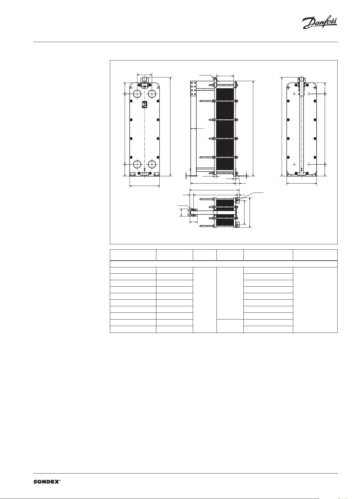
S43 / S43AD frames
395
29 7,5791314
F2
F1
F3
F4
7
7
280
W
50
20
140
Ø18
110
Ø100
50
L
L + 150
L + 80
L1
1402, 5
280
B2 B1
B3
H
B4
14
60
100
W
50
W
620
Ø25
Drawing of S43 IS16 frame
Number of plates
L (frame length)
1)
(mm)
W
(mm)
H
(mm)
Weight max, empt y
(kg)
2)
Connection type
S43 (S43AD) IS16
7 – 64 (7 - 54) 667
1161 (1276 )
65 – 137 (55 - 116) 1067 140 6 (1507)
138 – 191 (117 - 162) 1367 1591 (1678)
192 – 228 (163 - 193) 1567 172 2 (1793)
229 – 319 (194 - 270) 2067 2030 (2081)
320 – 410 (271 - 346) 2567 2345 (2365)
770
30 .31”
790
31.10 ”
1502 .5
59.15”
DN 200 flange or 8”
411 – 500 (347 - 423) 3067 2658 (2653)
501 – 682 (424 - 577) 4067 3290 (3228)
S43 IS25
7 − 62 677
1334
63 − 133 1077 1632
134 – 187 1377 1857
188 – 223 1577 2007
224 – 312 2077 2379
790
31.10 ”
1502 .5
59.15”
DN 200 flange or 8”
313 – 401 2577 2752
402 – 491 3077 312 8
492 – 669 4077 3873
1)
the indicate d maximum number of pla tes is based on the minimum plate thi ckness allowable for the PN le vel of the unit;
2)
the maximum w eight of the empty unit with t he maximum allowable nu mber of plates;
*)
PNclass 10 bar is avai lable on request
6 | VD.JQ.P1.02 | 2019.07
Page 7

Data sheet S43 / S43AD / S65 / S100 / S100AD / S100TY / S130 / S131 / S152 / S221 / S229 (DN 200 / 8”)
Dimensions (continued)
Non-sanitary applications
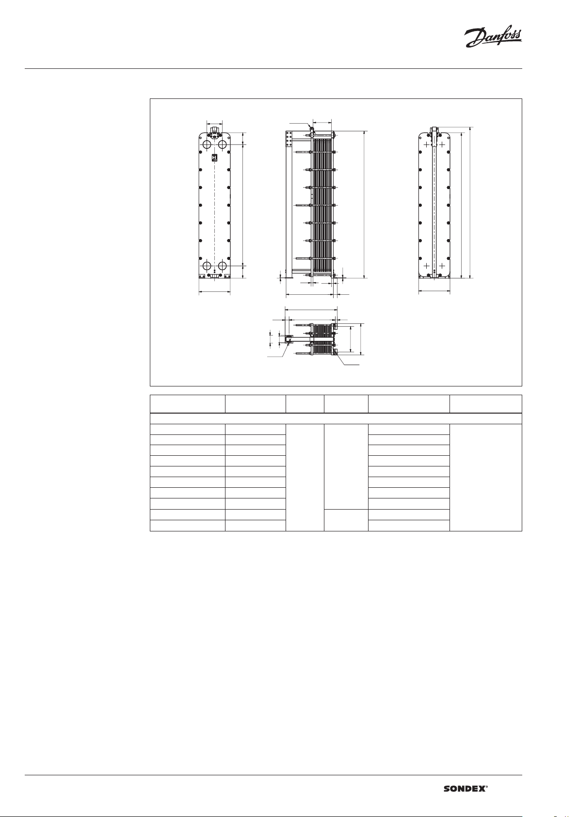
S65 frames
1702, 5
395
F1
F2
1091 297,5314
F3
F4
280
W
50
Ø100
L1
B1
B2
H
1702, 5
B3
7
7
50 60
14
100L
B4
280
W
L + 150
20
L + 80
50
Ø18
140
110
W
620
Ø25
Drawing of S65 IS16 frame
Number of plates
L (frame length)
1)
(mm)
W
(mm)
H
(mm)
Weight max, empt y
(kg)
2)
Connection type
S65 IS16
7 − 64 667
1430
65 − 137 1067 173 7
138 – 191 1367 1971
192 – 228 1567 2137
229 – 319 2067 2523
770
30 .31”
1802 .5
70.96”
DN 200 flange or 8”
320 – 410 2567 2921
411 – 500 30 67 3316
501 – 682 4067 4114
S65 IS25
7 − 61 677
1690
62 − 133 1077 2050
134 – 186 1377 2326
187 – 222 1577 2521
223 – 311 2077 2991
790
31.10 ”
1802 .5
70.96”
DN 200 flange or 8”
312 – 400 2577 3443
401 – 490 3077 3919
491 – 668 4077 4862
1)
the indicate d maximum number of pla tes is based on the minimum plate thi ckness allowable for the PN le vel of the unit;
2)
the maximum w eight of the empty unit with t he maximum allowable nu mber of plates;
*)
PNclass 10 bar is avai lable on request
VD.JQ.P1.02 | 7 | 2019.07
Page 8

Data sheet S43 / S43AD / S65 / S100 / S100AD / S100TY / S130 / S131 / S152 / S221 / S229 (DN 200 / 8”)
Dimensions (continued)
Non-sanitary applications
S100 frames
29 7,51489314
395
F2
F1
Ø100
L1
2100,5
F3F4
280
7
7
50
60
L
14
60
100
W
L + 150
20
L + 80
50
395
B2
B1
H
B3
B4
280
W
Ø18
W
140
110
620
Ø25
Drawing of S100 IS16 frame
Number of plates
L (frame length)
1)
(mm)
W
(mm)
H
(mm)
Weight max, empt y
(kg)
2)
Connection type
S100 I S16
7 – 64 6 67
1805
65 – 137 10 67 2194
138 − 191 1367 2489
192 − 228 1567 2689
229 − 319 2067 318 8
320 − 410 2 567 3692
770
30 .31”
2198
(86. 53”)
DN 200 Flange or 8”
411 − 500 30 67 4193
501 − 682 4067 5204
683 − 864 5210
865 − 1046 6210 7267
790
31.10 ”)
2505.5
(98.64”)
6214
S100 I S25
7 - 61 677
2019
62 – 133 1077 2505
134 – 186 1377 2864
187 − 222 1577 3108
223 – 311 2077 3710
312 − 400 2577 4312
790
31.10 ”
2200.5
86.63”
DN 200 Flange or 8”
401 − 490 3077 4921
491 − 668 4 077 6125
669 − 847 5220
848 − 1025 6220 8944
1)
the indicate d maximum number of pla tes is based on the minimum plate thi ckness allowable for the PN le vel of the unit;
2)
the maximum w eight of the empty unit with t he maximum allowable nu mber of plates;
*)
PNclass 10 bar is avai lable on request
790
31.10 ”
2505.5
98.64”
7686
8 | VD.JQ.P1.02 | 2019.07
Page 9

Data sheet S43 / S43AD / S65 / S100 / S100AD / S100TY / S130 / S131 / S152 / S221 / S229 (DN 200 / 8”)
Dimensions (continued)
Non-sanitary applications
S100AD / S100TY frames
395
29 7,51489314
F2
F1
F3F4
280
W
Ø100
L1
2100,5
7
7
50
60
L
14
60
100
L + 150
20
L + 80
50
395
B2
B1
H
B3
B4
280
W
Ø18
W
140
110
620
Ø25
Drawing of S100 IS16 frame
Number of plates
1)
L (frame length)
(mm)
W
(mm)
H
(mm)
Weight max,
2)
empty
(kg)
Connection type
S100A D IS16
7 – 64 667
1935
55 – 119 1067 2327
120 − 165 1367 2608
166 – 196 1567 2798
197 – 270 20 67 3252
271 – 350 25 67 3737
790
31.10 ”
2200.5
86.64”
DN 200 flange or 8”
351 – 426 30 67 4203
427 – 580 40 67 5143
581 – 734 5210 6084
735 – 888 6210 7023
S100T Y IS16
7 64 667
1977
65 – 140 1067 2 415
141 – 195 1367 2735
196 – 231 15 67 2945
232 – 319 20 67 3459
320 – 413 2567 4003
770
30 .31”
2198
86. 53”
DN 200 flange or 8”
414 – 504 30 67 4533
505 – 686 40 67 5591
687 – 868 5210
869 – 1050 6210 7708
1)
the indicate d maximum number of pla tes is based on the minimum plate thi ckness allowable for the PN le vel of the unit;
2)
the maximum w eight of the empty unit with t he maximum allowable nu mber of plates;
*)
PNclass 10 bar is avai lable on request
790
(31.10 ”)
2505.5
(98.64”)
6650
VD.JQ.P1.02 | 9 | 2019.07
Page 10

Data sheet S43 / S43AD / S65 / S100 / S100AD / S100TY / S130 / S131 / S152 / S221 / S229 (DN 200 / 8”)
Dimensions (continued)
Non-sanitary applications
S130 fra mes
315 1891 300
Ø100
F1
F2
L1
B1
B2
H
2506
2551
150
F4
F3
B4
B3
14
395
W
20
60
L
60
L + 125
100
160
200
L - 25
50
620
Ø25
Ø25
Drawing of S130 IS16 f rame
Number of plates
1)
L (frame length)
(mm)
W
(mm)
H
(mm)
Weight max, empt y
(kg)
2)
Connection type
S130 IS16
7 – 64 810
2497
65 – 140 1210 3043
141 – 195 1510 34 41
196 – 231 1710 3703
232 – 319 2210 4344
320 – 413 2710 5022
770
30 .31”
2651
104.37 ”
DN 200 flange or 8”
414 – 504 3210 5681
505 – 686 4210 6854
687 – 868 5210
869 – 1050 6210 9337
2908
114 .4 9”
8048
S130 IS25
7 – 61 825
2276
62 - 133 122 5 2737
134 - 186 152 5 3114
187 - 222 17 25 3309
223 - 311 2225 3882
312 - 400 2725 4464
790
31.10 ”
2655
104.53 ”
DN 200 flange or 8”
401 - 490 3225 5036
491 - 668 4225 6191
669 - 847 5225
848 - 1025 6225 8491
1)
the indicate d maximum number of pla tes is based on the minimum plate thi ckness allowable for the PN le vel of the unit;
2)
the maximum w eight of the empty unit with t he maximum allowable nu mber of plates;
*)
PNclass 10 bar is avai lable on request
2907
114 .4 5”
7336
10 | VD.JQ.P1.02 | 2019.07
Page 11
Data sheet S43 / S43AD / S65 / S100 / S100AD / S100TY / S130 / S131 / S152 / S221 / S229 (DN 200 / 8”)
Dimensions (continued)
Non-sanitary applications
S131 f rames
1891 300315
395
F1
F1
F2
F2
H
F3
F3
F4
F4
W
100
Ø100
150
20
50
L
L + 125
L - 25
L1
B2
B2
B1
B1
2551
50
14
100
Ø25
50
H
1891 300315
B3
B3
B4
B4
W
Ø25
W
200
160
650
200
Drawing of S131 IS10 frame
Number of plates
1)
L (frame length)
(mm)
W
(mm)
H
(mm)
Weight max, empt y
(kg)
2)
Connection type
S131 IS10
7 – 33 810
2276
34 – 70 1210 2737
71 – 98 1510 3 114
99 – 116 17 10 3309
117 – 162 2210 3882
163 – 209 2710 4464
800
31. 50”
2651
104.37 ”
DN 200 flange or 8”
210 – 255 3210 5036
256 – 348 4210 6191
349 – 440 5210
441 – 533 6210 8491
1)
the indicate d maximum number of pla tes is based on the minimum plate thi ckness allowable for the PN le vel of the unit;
2)
the maximum w eight of the empty unit with t he maximum allowable nu mber of plates;
2908
114 .4 9”
7336
VD.JQ.P1.02 | 11 | 2019.07
Page 12

Data sheet S43 / S43AD / S65 / S100 / S100AD / S100TY / S130 / S131 / S152 / S221 / S229 (DN 200 / 8”)
Dimensions (continued)
Non-sanitary applications
S152 frame s
300315
2191
Ø100 L1
F2
F1
395
2806
F3
F4
150
20
W
100
60
L + 125
L - 25
60
L
100
50
2851
14
395
W
Ø25
H
Ø25
200
160
620
Drawing of S152 IS16 frame
Number of plates
1)
L (frame length)
(mm)
W
(mm)
H
(mm)
Weight max, empt y
(kg)
2)
Connection type
S152 IS16
7 – 64 810
2804
65 – 137 1210 3402
138 – 191 1510 3845
192 – 228 17 10 4147
229 – 319 2210 4893
320 – 410 2710 5637
770
30 .31”
2951
116.18 ”
DN 200 flange or 8”
411 – 500 3210 6376
501 – 682 4210 7866
683 – 866 5225
867 – 1048 6225 108 61
3208
126 .30 ”
9370
S152 I S25
7 – 63 825
3053
64 – 134 1225 3687
135 – 188 152 5 4194
189 – 224 1725 4548
225 – 313 2225 5356
314 – 402 2725 6208
770
30 .31”
2950
116.14 ”
DN 200 flange or 8”
403 – 491 3225 7138
492 – 670 4225 8 878
671 – 850 5225
851 – 1029 6225 12071
1)
the indicate d maximum number of pla tes is based on the minimum plate thi ckness allowable for the PN le vel of the unit;
2)
the maximum w eight of the empty unit with t he maximum allowable nu mber of plates;
*)
PNclass 10 bar is avai lable on request
3208
126 .30 ”
1036 8
12 | VD.JQ.P1.02 | 2019.07
Page 13

Data sheet S43 / S43AD / S65 / S100 / S100AD / S100TY / S130 / S131 / S152 / S221 / S229 (DN 200 / 8”)
Dimensions (continued)
Non-sanitary applications
S221 frames
395
F1
F4
Drawing of S221 IS16 frame
Ø100
L1
395
300
B2
F2
3751
B1
H
150
F3
20
315 3091
W
60
14
60
100L
B4
B3
W
L + 125
100
200
160
Ø25
L - 25
50
W
620
Ø25
Number of plates
1)
L (frame length)
(mm)
W
(mm)
H
(mm)
Weight max, empt y
(kg)
2)
Connection type
S221 IS16
7 – 64 810
3392
65 – 140 1210 4159
141 – 195 1510 4722
196 – 231 1710 510 6
232 – 319 2210 6005
320 – 413 2710 6967
770
30 .31”
3851
151.61
DN 200 flange or 8”
414 – 504 3210 8010
505 – 686 4210 9935
687 – 868 5210
869 – 1050 6210 13919
4108
(161.73” )
118 45
S221 IS25
7 – 61 825
4 411
62 – 133 1225 5316
134 – 186 1525 5986
187 – 222 1725 6439
223 – 311 2225 7561
312 – 400 2725 8682
790
31.10 ”
3849
151.53”
DN 200 flange or 8”
401 – 490 3225 9815
491 – 668 4225 12058
669 – 847 5225
848 – 1025 6225 16557
1)
the indicate d maximum number of pla tes is based on the minimum plate thi ckness allowable for the PN le vel of the unit;
2)
the maximum w eight of the empty unit with t he maximum allowable nu mber of plates;
*)
PNclass 10 bar is availabl e on request
4107
161.69 ”
14313
VD.JQ.P1.02 | 13 | 2019.07
Page 14
Data sheet S43 / S43AD / S65 / S100 / S100AD / S100TY / S130 / S131 / S152 / S221 / S229 (DN 200 / 8”)
Dimensions (continued)
Non-sanitary applications
S229 frames
F1
F4
Drawing of S229 IS10 frame
395
W
L1
Ø100
300
B1
F2
3091
F3
315
20
50
50
3751
14
L 100
B2
H
3706
B4
B3
W
L + 125
100
200
L - 25
160
50
W
650
Ø25
Ø25
Number of plates
1)
L (frame length)
(mm)
W
(mm)
H
(mm)
Weight max, empt y
(kg)
2)
Connection type
S229 IS10
7 – 33 800
3307
34 – 70 120 0 3980
71 – 98 150 0 4488
99 – 116 1700 4 815
117 – 162 2200 5651
163 – 209 2700 6503
800
31. 50”
3850
151.61”
DN 200 flange or 8”
210 – 255 3200 7340
256 – 348 4200 9027
349 – 440 5200
441 – 533 6200 123 87
1)
the indicate d maximum number of pla tes is based on the minimum plate thi ckness allowable for the PN le vel of the unit;
2)
the maximum w eight of the empty unit with t he maximum allowable nu mber of plates;
4108
161.73”
10700
14 | VD.JQ.P1.02 | 2019.07
Page 15

Data sheet S43 / S43AD / S65 / S100 / S100AD / S100TY / S130 / S131 / S152 / S221 / S229 (DN 200 / 8”)
VD.JQ.P1.02 | 15 | 2019.07
Page 16

Data sheet S43 / S43AD / S65 / S100 / S100AD / S100TY / S130 / S131 / S152 / S221 / S229 (DN 200 / 8”)
| DHS-SRMT/SI | 2019.0716 | VD.JQ.P1.02
 Loading...