

Page 1
Data sheet
Gasketed Plate Heat Exchangers (DN 100 / 4”)
S21 / S21A / S21SE / S22 / S36 / S37 / S45SE / S47 / S55SE / S64
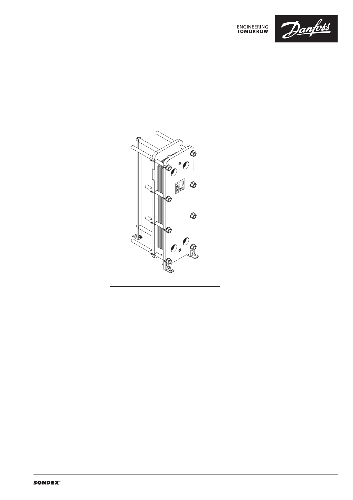
Description
SONDEX® gasketed plate heat exchangers are
the ideal choice for a wide range of applications
across numerous market segments.
We have the largest plate portfolio in the
world, and we customize each heat exchanger
to meet your exact requirements. Innovative
technologies and smart design make our
gasketed plate heat exchangers a stellar
investment.
Benefits:
• Individually customized solution that
perfectly matches your requirements and
lowers your energy consumption.
• High performance and a low pressure
drop eliminate unnecessary burdens on
your system and optimize overall system
performance.
• The design results in a compact solution with
a small footprint, simple installation, and easy
access for maintenance.
Common applications:
• HVAC industry
• Marine/offshore industry
• Dairy/food/beverage industry
• Sugar industry
• Biogas industry
• Pulp and paper industry
• Heavy industry
• Mining industry
• Petrochemical industry
• Chemical industry DN 100
Main data:
• Min. temperature −10 °C
• Max. temperature 180 °C
• Max. working pressure 16 / 25 bar (10 bar on
request)
• Water and different fluids, steam
• Connection size 4”or DN 100
Approvals:
• Please contact your local Danfoss/SONDEX®
sales representative for an overview of the
available approvals in your region
Construction standard:
• EN13445 (PED 2014/68/EU)
• ASME sec VIII, Div. 1
| 2019.05 VD.JQ.M1.02 | 1
Page 2
Data sheet S21 / S21A / S21SE / S22 / S36 / S37 / S45SE / S47 / S55SE / S64 (DN 100)
Naming of units
S21A-IG16-21-TKTL89
3)
2)
1)
1)
Type of heat exchanger:
TKTL89 - Plate grouping
21 - Number of plates in the heat exchanger
16 - Design pressure of the heat exchanger
IG - Frame type
21A – Type of heat exchanger
S – Gasketed heat exchanger
21 - …
Letter A shows type of the attachment of gasket to plate:
e.g. 21 (without A) – SonderLock
21A (with A) – Hang-on
SE - SonderLock Energy Saving plate design
2)
Description of frame types:
There are few different frame types which can be offered for different applications and duties.
IS – with suspension roller,
IG – without suspension roller,
FS – food/sanitary with suspension roller,
FG - food/sanitary,
ST – simple design of frame with threaded connections
3)
Channel grouping:
In this example, the heat exchanger combines TK and TL channels. The share of TL channels equals
89% of the total number of channels.
The number of channels is defined as “the number of plates - 1”.
TK - short thermal length
TM - medium thermal length
TL - long thermal length
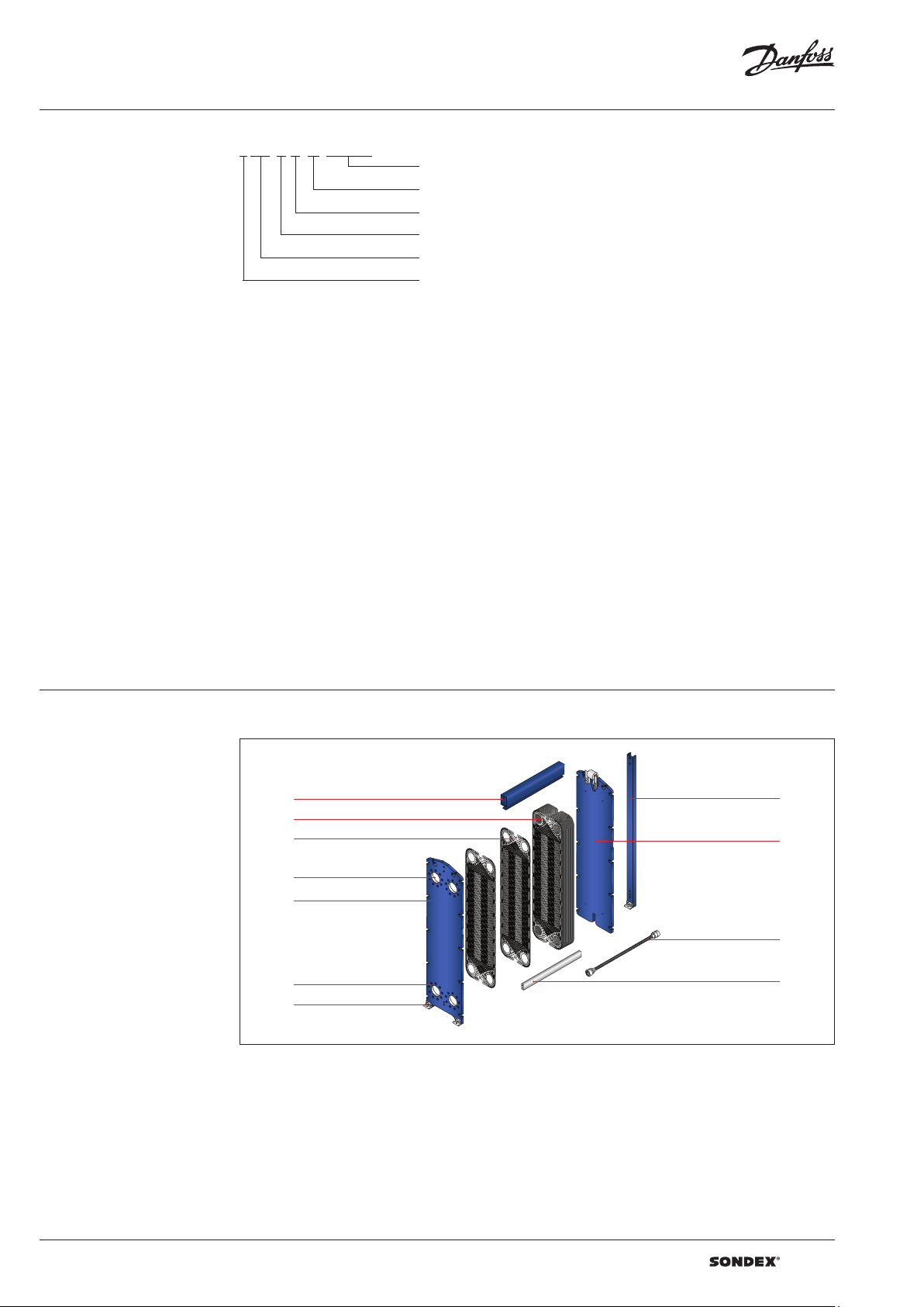
Heat exchanger design
Gasketed heat exchangers consist of
Carrying Bar
Plate Pack
Plate
Connections
Head
Flange Connections
Foundation Feet
Column
Follower
Tie Bolt
Guiding Bar
Anatomy of a SONDEX® plate heat exchanger - IS frame.
2 | VD.JQ.M1.02 | 2019.05
Page 3
Data sheet S21 / S21A / S21SE / S22 / S36 / S37 / S45SE / S47 / S55SE / S64 (DN 100)
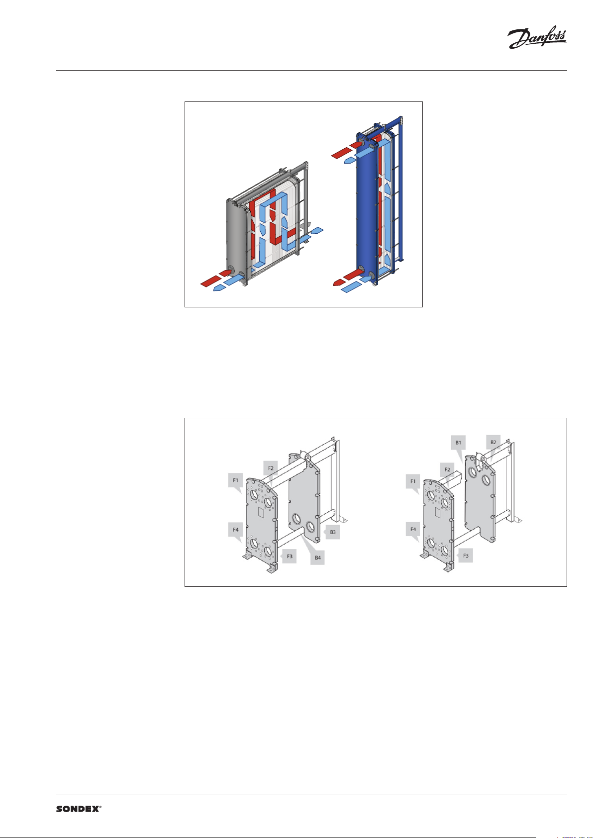
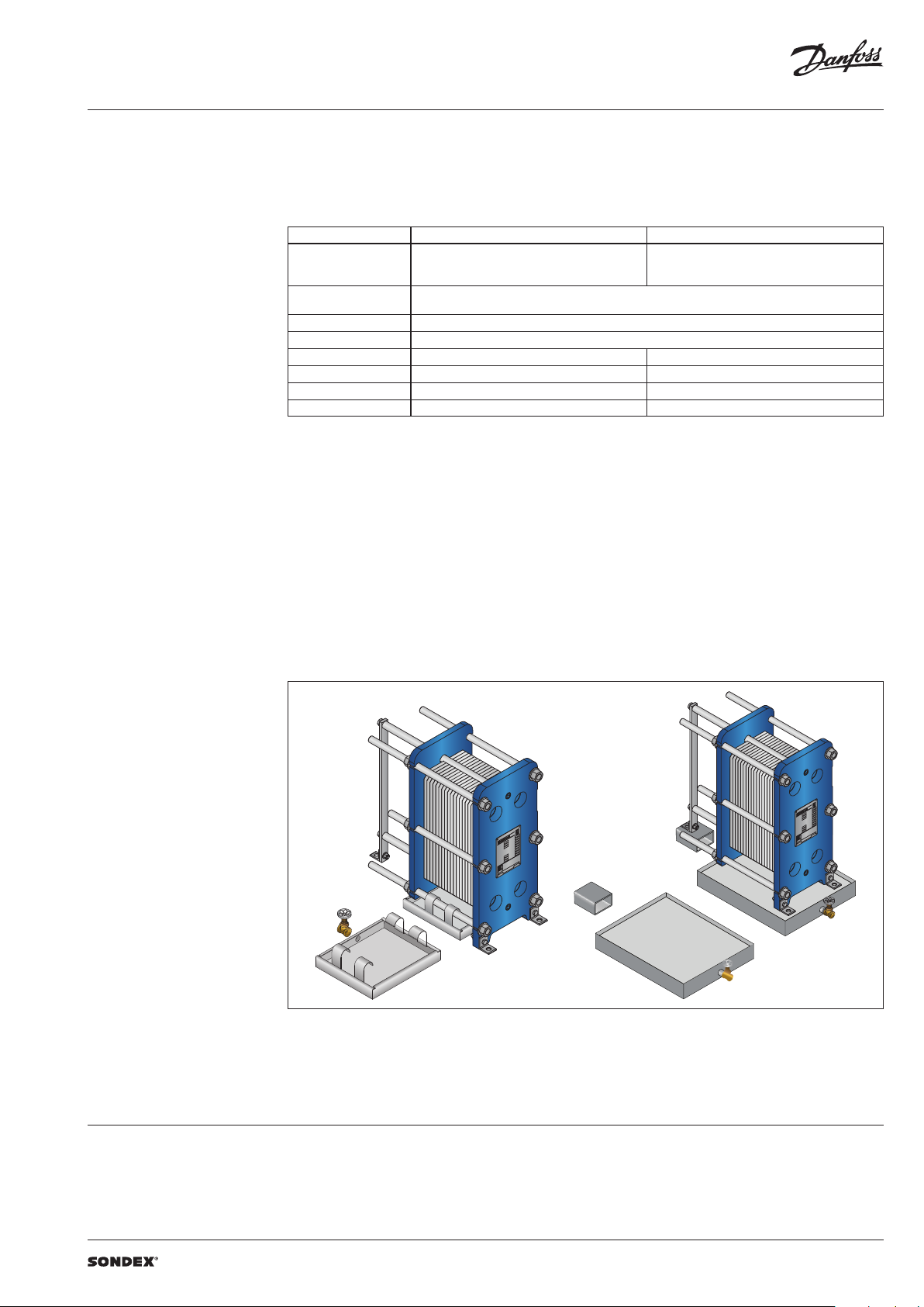
To the left: A multi-pass solution with connections
Heat exchanger design
(continued)
Multi-pass design
on the follower and the head.
To the right: A single-pass solution with
all connections on the head.
Connections
The heat exchanger may have connections on
both front and back-end sides of the unit.
Connections on the front-end plate are marked
with F and connections on the back-end plate
are marked with B. The numbers 1, 2, 3 and 4
designate the position of the connection on the
end-plate from the top-left port clockwise.
VD.JQ.M1.02 | 3 | 2019.05
Page 4
Data sheet S21 / S21A / S21SE / S22 / S36 / S37 / S45SE / S47 / S55SE / S64 (DN 100)
SONDEX®
plate
range
Common
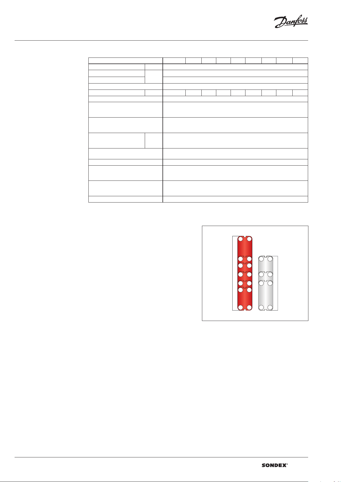
Technical data Heat exchanger S21 / S21A / S21SE / S22 / S36 / S37 / S45SE / S47 / S55SE / S64 (DN 100)
Typ e S21(S21A) S21SE S22 S36 S37 S45SE S47 S55SE S64
Max. working pressure PN (bar) (10)1), 16, 25
Max. operating temperature
Min. operating temperature -10
Flow medium Water and different fluids, steam
Volume / channel l 0,6 0.48 0.75 0,9 1.2 0.81 1.15 1 .11 1.7
Connection size DN 100 / 4"
Connection type
Plate material
Plate thickness mm
Gasket material
Gasket attachment type Hang-on; Sonder Lock
Liners in connections
Frame
Frame painting specification Painting available for corrosion categories C2L, C4M, C5M
1)
Not available f or all frame variations
2)
SonderSafe – do uble plate
°C
• DN 100/4” flanges. Carbon steel, rubberlined or cladded with AISI 316L
(other materials available on request)
• DN 80 / 3” Dair y union (for food/sanitary industry frames only)
Stainless steel EN 1.4404 (AISI 316L), EN 1.4301 (AISI 304), SMO254, Hastelloy C276,
titanium Gr.1
Other materials available on request
0.4; 0.5; 0.6; 0.7 (ti)
2 x 0.4 SonderSafe plates
Other thicknesses available on request
NBR, EPDM, FKM
Other materials available on request
• Rubber NBR, EPDM, FKM
• Stainless steel EN 1.4404 (AISI 316L), EN 1.4301 (AISI 304), SMO254, Hastelloy C276,
titanium Gr.1
• Painted frame, color RAL 5010 (other colors available on request)
• Stainless steel frame, designed for the sanitary applications (e.g. food and dairy
industries)
1)
2)
Up to 180
Using the right plate for each individual duty
is very important, as it greatly impacts the
efficiency of the entire installation.
It is important that the length of the plates and
the type of pattern match the requirements of
individual thermal duty.
We have developed a wide plate portfolio to
provide the perfect plate and connection size for
any duty.
No application is too small or too big for us - we
provide the optimal technical solution every
time.
Our extensive SONDEX® plate portfolio
includes plates that lie outside the commonly
manufactured plate sizes to cover all thermal
duties optimally.
plate
range
4 | VD.JQ.M1.02 | 2019.05
Page 5
Data sheet S21 / S21A / S21SE / S22 / S36 / S37 / S45SE / S47 / S55SE / S64 (DN 100)
Accessories Insulation
Recommended applications:
The insulation jacket for the plate heat exchanger
is used in different applications with high
temperatures and cooling systems.
Application Heating Cooling
Material
Outer cap
Internal insulation 0.05 mm aluminium foil
Panel fixation Plastic rivets
Temperature 20 … 200 °C -50 … -80 °C
U-value 0.55 W/m2K 0.3 8 W/m2K
Insulation class 3
Heat loss 17.1 W/m
Please note:
Inlet and outl et temperatures in the exch anger have been based on 9 0/50 – 30/70 °C.
1)
The loss of he ating/cooling is stated per m2 surface on the insu lation jacket
The bottom o f the heat exchanger is not insu lated and this fact has been e xcluded.
A possible loss of ve ntilation, largely dep endent on the mounting of the h eat exchanger, has not been take n into account either.
45 mm mineral wool
Not flammable
DIN EN 4102A2
1 mm aluminium
“Stucco” Embossed
1)
2
Drip trays
Recommended applications:
The drip tray is available in two types. A “failsafe” solution which prevents water or liquid
from leaking onto the floor, or when the
heat exchanger is dismantled, or opened for
inspection and maintenance. And an insulated
drip tray for cooling applications, which
Materials
Drip tray consists of:
• 1 mm galvanized steel frame
• Hanging brackets in galvanized steel
• 60 mm Polyurethane insulation for cooling
applications
• Draining valve.
collects condensate formed outside of the plate
heat exchanger.
40 mm PU-foam
DIN 4102-1 B2
1)
4
-
Spare parts
Spare parts for gasketed heat exchangers, such
as plates, gaskets, frame parts can be ordered for
maintenance, repair, increasing heat exchanger
capacity, etc.
Selection and ordering Please contact your local SONDEX® or Danfoss
sales representative for the selection and / or
ordering of the heat exchangers, spare parts, and
accessories.
Please contact your local Danfoss or SONDEX®
sales representative to provide you with
information on spare parts available for gasketed
heat exchangers.
For contact information please visit
https://www.danfoss.com/en/contact-us.
VD.JQ.M1.02 | 5 | 2019.05
Page 6
Data sheet S21 / S21A / S21SE / S22 / S36 / S37 / S45SE / S47 / S55SE / S64 (DN 100)
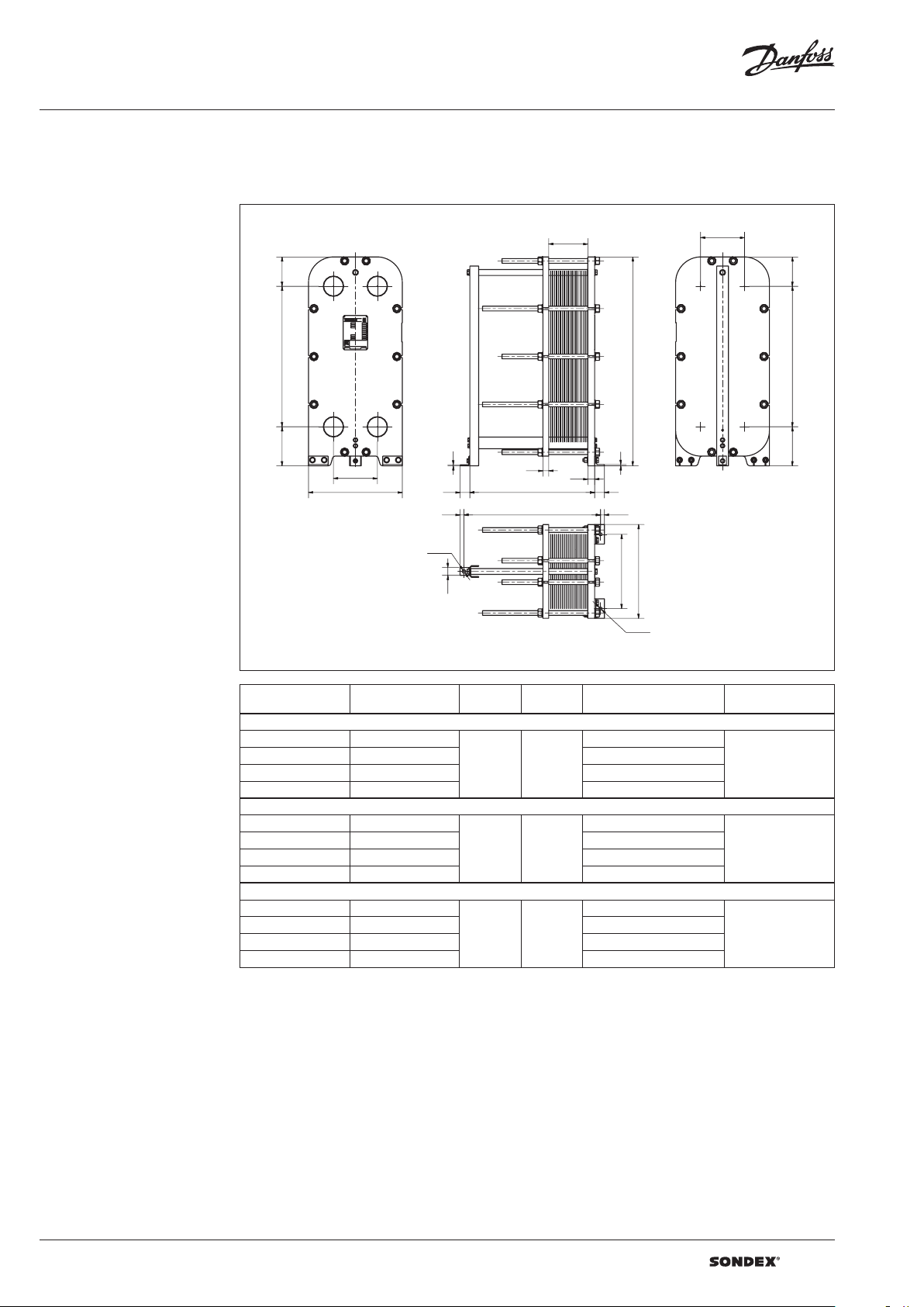
Dimensions
Non-sanitary applications
Any connection can be used for primary side in.
All the rest are made correspondingly.
S21 / S21A / S22 frames
150
F1
719
F4
200
225
W
F2
F3
5
50
20
Ø18
40
30
L
L + 60
L1
225
150
B1
B2
H
B3
719200
B4
7
35
50
20
W
380
Ø18
Drawing of S21 / S21A / S22 IG16 frame
Number of plates
L (frame length)
1)
(mm)
W
(mm)
H
(mm)
Weight max, empt y
(kg)
2)
Connection type
S21 I G16
7 - 42 439
43 - 60 539 349
61 - 79 639 382
480
18.8 9”
1069
42.09”
320
DN 100 flange or 4”
80 - 152 1039 499
S21A I G16
7 - 42 439
43 - 60 539 349
61 - 79 639 382
480
18.8 9”
1069
42.09”
320
DN 100 flange or 4”
80 - 152 1039 499
S22 IG16
7 - 25 439
26 - 40 539 321
41 - 54 639 347
480
18.8 9”
1069
42.09”
296
DN 100 flange or 4”
55 - 112 1039 443
1)
the indicate d maximum number of pla tes is based on the minimum plate thi ckness allowable for the PN le vel of the unit;
2)
the maximum w eight of the empty unit with t he maximum allowable nu mber of plates;
*)
PNclass 10 bar is avai lable on request
6 | VD.JQ.M1.02 | 2019.05
Page 7

Data sheet S21 / S21A / S21SE / S22 / S36 / S37 / S45SE / S47 / S55SE / S64 (DN 100)
Dimensions (continued)
Non-sanitary applications
S21 / S21A / S22 frames
184
F2
F1
719
F4 F3
205
225
W
Ø70 L1
B1
B2
110 8
5
35
L
H
110 8
B3
7
35
50
225
W
45
H
B4
L+59
L+19
60
40
Ø18
50
20
Ø18
W
380
Drawing of S21/S21A IS16 frame
Number of plates
L (frame length)
1)
(mm)
W
(mm)
H
(mm)
Weight max, empt y
(kg)
2)
Connection type
S21 / S21A IS16
3)
7 - 70
71 - 142
143 - 197
198 - 233
234 - 324
3)
3)
3)
3)
680
1080 701
138 0 802
158 0 868
495
19.4 8”
1178
46.38”
568
2080 1036
DN 100 flange or 4”
S21 / S21A IS25
3)
7 - 67
68 - 139
140 - 192
193 - 228
229 - 317
3)
3)
3)
3)
685
1085 752
1385 86 4
1585 941
495
19.4 8”
1178
46.38”
600
2085 112 9
DN 100 flange or 4”
S22 IS16
3)
7 - 47
48 - 105
106 - 149
150 - 178
179 - 250
3)
3)
3)
3)
680
1080 649
138 0 735
158 0 792
495
19.4 8”
1178
46.38”
535
2080 933
DN 100 flange or 4”
S22 IS25
3)
7 - 54
3)
55 - 111
3)
112 - 154
3)
155 - 182
3)
183 - 254
1)
the indicate d maximum number of pla tes is based on the minimum plate thi ckness allowable for the PN le vel of the unit;
2)
the maximum w eight of the empty unit with t he maximum allowable nu mber of plates;
3)
the indicated ma ximum number of plates is fo r units without intermedi ate frames. Adding an interm ediate frame reduces the
maximum all owable number of plates in t he unit;
*)
PNclass 10 bar is avai lable on request
685
1085 689
1385 785
1585 849
495
19.4 8”
1178
46.38”
561
2085 1010
DN 100 flange or 4”
VD.JQ.M1.02 | 7 | 2019.05
Page 8

Data sheet S21 / S21A / S21SE / S22 / S36 / S37 / S45SE / S47 / S55SE / S64 (DN 100)
Dimensions (continued)
Non-sanitary applications
S21SE frames
225
L1
150
B1
F1
F2
720206
F4
F3
5
W
50
20
60
40
L
L + 100
L + 60
35
35
H
7
50
20
W
380
B2
B3
B4
225
W
Ø18
Ø18
Drawing of S21SE IG16 f rame
Number of plates
L (frame length)
1)
(mm)
W
(mm)
H
(mm)
Weight max, empt y
(kg)
2)
Connection type
S21SE IG16
7 - 46 439
47 - 66 539 383
67 - 86 639 418
480
18.8 9”
1076
42.4”
349
DN 100 flange or 4”
87 - 166 1039 552
S21SE IS16
7 - 76 685
77 - 156 1085 618
157 - 216 1385 722
217 - 256 1585 796
495
19.5”
118 5
46.65”
481
DN 100 flange or 4”
257 - 356 2085 969
S21SE IS25
7 - 72 695
73 - 150 1095 740
151 - 209 1395 844
210 - 249 1595 951
495
19.5”
118 5
46.65”
582
DN 100 flange or 4”
250 - 347 2095 1151
1)
the indicate d maximum number of pla tes is based on the minimum plate thi ckness allowable for the PN le vel of the unit;
2)
the maximum w eight of the empty unit with t he maximum allowable nu mber of plates;
*)
PNclass 10 bar is avai lable on request
8 | VD.JQ.M1.02 | 2019.05
Page 9

Data sheet S21 / S21A / S21SE / S22 / S36 / S37 / S45SE / S47 / S55SE / S64 (DN 100)
Dimensions (continued)
Sanitary applications
S21 / S21A / S22 frames
225
150719
F1
F4
150
386
89 /117
min/max
W
L1
30 30
225
150719150
B1
F2
30
F3
1019
L - 27.5
B2
H
B4
B3
W
L
W
Drawing of S21/S22 FG10 f rame
Number of plates
1)
L (frame length)
(mm)
W
(mm)
H
(mm)
Weight max, empt y
(kg)
2)
Connection type
S21 / S21A / (S22) FG10
7 - 38 (7 - 22) 460
39 - 57 (23 - 37) 560 321 (298)
58 - 75 (38 - 52) 660 34 7 (321)
480
18.8 9”
110 8 - 113 6
43.62” - 44.72”
4)
292 (274)
DN 100 flange or 4”
76 - 150 (53 - 110) 1060 459 (414)
S21 / S21A / (S22) FS10
7 - 713) (7 - 48)
49 - 1453) (49 - 107)
108 - 2003) (108 - 151)
201 - 2373) (152 - 180)
238 - 3303) (181 - 254)
331 - 4233) (255 - 327)
424 - 5153) (328 - 401)
516 - 7003) (402 - 548)
1)
the indicate d maximum number of pla tes is based on the minimum plate thi ckness allowable for the PN le vel of the unit;
2)
the maximum w eight of the empty unit with t he maximum allowable nu mber of plates;
3)
the indicated ma ximum number of plates is fo r units without intermedi ate frames. Adding an interm ediate frame reduces the
maximum all owable number of plates in t he unit;
4)
the height of the h eat exchanger can be mod ified with special adj ustable feet.
3)
3)
3)
3)
3)
3)
3)
3)
700
564 (4 86)
110 0 669 (574)
140 0 747 (640)
160 0 799 (684)
2100 931 (794)
700
27. 56 ”
54.6055.79”
138 7-1417
4)
2600 1063 (90 4)
3100 1194 ( 1015 )
4100 1456 (1235)
DN 100 flange or 4”
VD.JQ.M1.02 | 9 | 2019.05
Page 10

Data sheet S21 / S21A / S21SE / S22 / S36 / S37 / S45SE / S47 / S55SE / S64 (DN 100)
Dimensions (continued)
Non-sanitary applications
S36 frames
F1
F4
225
Ø70
L1
184
B1
F2
1065
45
F3
204
5
W
50
50
50
L
1453
50
B2
H
B3 B4
W
L + 59
20
L + 19
20
Ø18
60
40
W
395
50
Ø18
Drawing of S36 IS25 frame
Number of plates
1)
L (frame length)
(mm)
W
(mm)
H
(mm)
Weight max, empt y
(kg)
2)
Connection type
S36 IG16
7 - 42 434
43 - 60 534 469
61 - 79 634 512
480
18.8 9”
1415
55.71”
431
DN 100 flange or 4”
80 - 152 1034 677
S36 I S16
3)
7 - 70
71 - 142
143 - 197
198 - 233
234 - 324
325 - 415
3)
3)
3)
3)
3)
680
659
1080 836
138 0 970
158 0 1059
480
18.8 9”
1523
59.96”
2080 1283
2580 150 6
DN 100 flange or 4”
S36 IS25
3)
7 - 66
3)
67 - 137
3)
138 - 191
3)
192 - 226
3)
227 - 316
3)
317 - 405
1)
the indicate d maximum number of pla tes is based on the minimum plate thi ckness allowable for the PN le vel of the unit;
2)
the maximum w eight of the empty unit with t he maximum allowable nu mber of plates;
3)
the indicated ma ximum number of plates is fo r units without intermedi ate frames. Adding an interm ediate frame reduces the
maximum all owable number of plates in t he unit;
*)
PNclass 10 bar is avai lable on request
695
775
1095 977
1395 1131
1595 1231
495
19.45”
1523
59.96”
2095 148 6
2595 1740
DN 100 flange or 4”
10 | VD.JQ.M1.02 | 2019.05
Page 11

Data sheet S21 / S21A / S21SE / S22 / S36 / S37 / S45SE / S47 / S55SE / S64 (DN 100)
Dimensions (continued)
Non-sanitary applications
S37 frames
238
171
F1
F2
1070200
F4
H
F3
35
L + 55
Ø18
180
140
70
Drawing of S37 IS16 frame
Number of plates
1)
L (frame length)
(mm)
W
(mm)
S37 I S16
3)
7 - 38
3)
43 - 105
3)
61 - 155
3)
80 - 188
3)
325 - 271
3)
7 - 355
3)
71 - 438
3)
143 - 605
1)
the indicate d maximum number of pla tes is based on the minimum plate thi ckness allowable for the PN le vel of the unit;
2)
the maximum w eight of the empty unit with t he maximum allowable nu mber of plates;
3)
the indicated ma ximum number of plates is fo r units without intermedi ate frames. Adding an interm ediate frame reduces the
maximum all owable number of plates in t he unit;
*)
PNclass 10 bar is avai lable on request
695
1095 755
1395 885
1595 972
2095 1188
480
18.8 9”
2595 14 07
3095 1623
4095 2059
L
L
1510.5
59.47”
H
(mm)
L1
35
35
20
Weight max, empt y
B2 B1
1441
B3
7
20
W
1070 171
B4
200
Ø18
W
380
2)
(kg)
Connection type
580
DN 100 flange or 4”
H
VD.JQ.M1.02 | 11 | 2019.05
Page 12

Data sheet S21 / S21A / S21SE / S22 / S36 / S37 / S45SE / S47 / S55SE / S64 (DN 100)
Dimensions (continued)
Sanitary applications
S37 frames
108
1070
110
F1 F2
F4
238
390
L1
128 8
F3
25
25
L - 27.5
238
B1B2
H
B3
B4
W
87 -117
min/max
L
W
Drawing of S37 FG10 frame
Number of plates
1)
L (frame length)
(mm)
W
(mm)
H
(mm)
Weight max, empt y
(kg)
2)
Connection type
S37 F G10
7 - 26 455
27 - 43 555 362
44 - 60 655 404
460
18 .11”
54.1355,31”
1375 -1405
4)
321
DN 80 flange or 3”
61 - 126 1055 565
S37 FS10
3)
7 - 33
34 - 100
101 - 150
151 - 183
184 - 267
268 - 350
351 - 433
434 - 600
3)
3)
3)
3)
3)
3)
3)
723
813
112 3 966
1423 1081
1623 115 6
2123 13 49
700
27. 56 ”
1769. 5-1819. 5
69.66”71.63”
4)
2623 1539
3123 17 29
4123 2112
DN 80 flange or 3”
S37 F S16
3)
7 - 32
3)
32 - 99
3)
100 - 149
3)
150 - 182
3)
183 - 266
3)
267 - 349
3)
350 - 432
3)
433 - 599
1)
the indicate d maximum number of pla tes is based on the minimum plate thi ckness allowable for the PN le vel of the unit;
2)
the maximum w eight of the empty unit with t he maximum allowable nu mber of plates;
3)
the indicated ma ximum number of plates is fo r units without intermedi ate frames. Adding an interm ediate frame reduces the
maximum all owable number of plates in t he unit;
4)
the height of the h eat exchanger can be mod ified with special adj ustable feet.
*)
PNclass 10 bar is avai lable on request
723
573
112 3 726
1423 841
1623 916
2123 1109
700
2 7.5 6”
1769. 5-1819. 5
69.66”71.63”
4)
2623 129 9
3123 14 89
4123 187 2
DN 80 flange or 3”
12 | VD.JQ.M1.02 | 2019.05
Page 13

Data sheet S21 / S21A / S21SE / S22 / S36 / S37 / S45SE / S47 / S55SE / S64 (DN 100)
Dimensions (continued)
Non-sanitary applications
S45SE frames
F1
225
F4
221 113 8 184
Drawing of S45SE IS25 frame
495
Ø70
F2
H
F3
45
5
L1
1533
50
L
7
50
50
225
B2
B1
B3
B4
211 113 8 18 4
W
L + 59
20
L + 19
20
40
60
Ø18
50
W
380
Ø18
Number of plates
L (frame length)
1)
(mm)
W
(mm)
H
(mm)
Weight max, empt y
(kg)
2)
Connection type
S45 SE IG16
7 - 46 439
47 - 66 539 549
67 - 86 639 598
480
18.8 9”
1494
58.82”
498
DN 100 flange or 4”
87 - 166 1039 794
S45 SE IS16
7 - 76 685
77 - 156 1085 896
157 - 216 1385 1052
217 - 256 1585 115 7
495
19.4 8”
1603
6 3.11 ”
686
DN 100 flange or 4”
257 - 356 2085 1419
S45SE IS25
7 - 72 695
73 - 150 1095 1043
151 - 209 1395 1222
210 - 249 1595 13 44
495
19.4 8”
1603
6 3.11 ”
806
DN 100 flange or 4”
250 - 347 2095 1641
1)
the indicate d maximum number of pla tes is based on the minimum plate thi ckness allowable for the PN le vel of the unit;
2)
the maximum w eight of the empty unit with t he maximum allowable nu mber of plates;
3)
the indicated ma ximum number of plates is fo r units without intermedi ate frames. Adding an interm ediate frame reduces the
maximum all owable number of plates in t he unit;
*)
PNclass 10 bar is avai lable on request
VD.JQ.M1.02 | 13 | 2019.05
Page 14

Data sheet S21 / S21A / S21SE / S22 / S36 / S37 / S45SE / S47 / S55SE / S64 (DN 100)
Dimensions (continued)
Non-sanitary applications
S47 frames
225 L1
F1 F2
F4 F3
205 1841365
W
45
5
50
20
60
40
Ø70
40
L
L + 59
L + 19 20
Ø18
B2
B1
175 4
B3
7
40
50
205 1841365
225
W
H
B4
Ø18
W
380
Drawing of S47 IS25 frame
Number of plates
1)
L (frame length)
(mm)
W
(mm)
H
(mm)
Weight max, empt y
(kg)
2)
Connection type
S47 IG16
7 - 42 439
43 - 60 539 581
61 - 79 639 634
480
18.8 9”
1715
6 7.52”
529
DN 100 flange or 4”
80 - 151 1039 833
S47 IS16
3)
7 - 70
71 - 142
143 - 197
198 - 233
234 - 324
3)
3)
3)
3)
680
1080 1091
138 0 126 5
158 0 1379
480
18. 89”
1823
71.78”
862
2080 166 8
DN 100 flange or 4”
S47 IS2 5
3)
7 - 67
3)
68 - 139
3)
140 - 192
3)
193 - 228
3)
229 - 317
1)
the indicate d maximum number of pla tes is based on the minimum plate thi ckness allowable for the PN le vel of the unit;
2)
the maximum w eight of the empty unit with t he maximum allowable nu mber of plates;
3)
the indicated ma ximum number of plates is fo r units without intermedi ate frames. Adding an interm ediate frame reduces the
maximum all owable number of plates in t he unit;
*)
PNclass 10 bar is avai lable on request
685
1085 135 0
1385 1545
1585 1676
480
18. 89”
1824
71.81”
1088
2085 2001
DN 100 flange or 4”
14 | VD.JQ.M1.02 | 2019.05
Page 15

Data sheet S21 / S21A / S21SE / S22 / S36 / S37 / S45SE / S47 / S55SE / S64 (DN 100)
Dimensions (continued)
Sanitary applications
S47 frames
1982 36.1
120/16 0
min/max
498
F1
F2
Ø70
L1 53 498
B2
B1
60
1365 315.5
F4
225
630
F3
301.5
53
88
L - 56.6
L
450
W
B4
B3
225
380
H
1365301.5
Drawing of S47 FS10 frame
Number of plates
1)
L (frame length)
(mm)
W
(mm)
H
(mm)
Weight max, empt y
(kg)
2)
Connection type
S47 FG10
7 - 39 485
40 - 58 585 472
59 - 76 685 517
456
17.9 5”
175 4-178 2
69.05” - 70.15
4)
423
DN 100 flange or 4”
77 - 150 1085 703
S47 F S10
3)
7 - 71
3)
72 - 145
3)
146 - 200
3)
201 - 237
3)
238 - 330
3)
331 - 423
3)
424 - 515
3)
516 - 700
1)
the indicate d maximum number of pla tes is based on the minimum plate thi ckness allowable for the PN le vel of the unit;
2)
the maximum w eight of the empty unit with t he maximum allowable nu mber of plates;
3)
the indicated ma ximum number of plates is fo r units without intermedi ate frames. Adding an interm ediate frame reduces the
maximum all owable number of plates in t he unit;
4)
the height of the h eat exchanger can be mod ified with special adj ustable feet.
*)
PNclass 10 bar is avai lable on request
700
872
110 0 1049
140 0 1180
160 0 1270
2100 1492
700
2 7.5 6”
2160 - 2200
85 .04” 86.61”
4)
2600 1714
3100 1934
4100 2 377
DN 100 flange or 4”
VD.JQ.M1.02 | 15 | 2019.05
Page 16

Data sheet S21 / S21A / S21SE / S22 / S36 / S37 / S45SE / S47 / S55SE / S64 (DN 100)
Dimensions (continued)
Non-sanitary applications
S55SE frames
1841556211
F1
F4 F3
W
Ø70
L1
225
184
B2
F2
H
45
B1
1951
B3
B4
5
50
L
7
50
211 1556
50
L + 59
Ø18
L + 19
20
W
380
20
60
40
50
Ø18
Drawing of S55SE IS25 frame
Number of plates
1)
L (frame length)
(mm)
W
(mm)
H
(mm)
Weight max, empt y
(kg)
2)
Connection type
S55SE IG16
7 - 46 439
47 - 66 539 711
67 - 86 639 776
480
18.8 9”
1912
75.27 ”
646
DN 100 flange or 4”
87 - 166 1039 1029
S55SE IS16
7 - 76 685
77 - 130 1085 120 0
131 - 216 1385 1489
217 - 256 1585 1635
495
19.4 8”
2021
79.56”
988
DN 100 flange or 4”
257 - 356 2085 1995
S55SE IS25
7 - 72 695
73 - 150 1095 138 0
151 - 209 1395 1614
210 - 249 1595 1822
495
19.4 8”
2021
79.56”
1071
DN 100 flange or 4”
250 - 347 2095 2260
1)
the indicate d maximum number of pla tes is based on the minimum plate thi ckness allowable for the PN le vel of the unit;
2)
the maximum w eight of the empty unit with t he maximum allowable nu mber of plates;
*)
PNclass 10 bar is avai lable on request
16 | VD.JQ.M1.02 | 2019.05
Page 17

Data sheet S21 / S21A / S21SE / S22 / S36 / S37 / S45SE / S47 / S55SE / S64 (DN 100)
Dimensions (continued)
Non-sanitary applications
S64 frames
1841771
207
F1 F2
F4
225
W
Ø70
L1
1841771
B1
B2
H
2162
45
F3
5
50
40
L
7
45
50
B3
B4
207
225
W
L + 59
Ø18
20
L + 19
20
W
380
Ø18
Drawing of S64 IS25 f rame
Number of plates
1)
L (frame length)
(mm)
W
(mm)
H
(mm)
Weight max, empt y
(kg)
2)
Connection type
S6 4 IG16
7 - 41 434
42 - 60 534 741
61 - 78 634 810
480
18.8 9”
2121
83.50”
670
DN 100 flange or 4”
79 - 150 1034 1082
S64 IS16
3)
7 - 70
71 - 143
144 - 198
199 - 234
235 - 325
3)
3)
3)
3)
680
1080 135 8
138 0 1576
158 0 1719
480
18. 89”
2232
87.87”
1068
2080 2082
DN 100 flange or 4”
S64 IS25
3)
7 - 68
3)
69 - 140
3)
141 - 193
3)
194 - 229
3)
230 - 318
1)
the indicate d maximum number of pla tes is based on the minimum plate thi ckness allowable for the PN le vel of the unit;
2)
the maximum w eight of the empty unit with t he maximum allowable nu mber of plates;
3)
the indicated ma ximum number of plates is fo r units without intermedi ate frames. Adding an interm ediate frame reduces the
maximum all owable number of plates in t he unit;
*)
PNclass 10 bar is avai lable on request
705
110 5 1432
1405 1676
1605 18 41
480
18. 89”
2232
87.87”
110 2
2105 2251
DN 100 flange or 4”
VD.JQ.M1.02 | 17 | 2019.05
Page 18
Data sheet S21 / S21A / S21SE / S22 / S36 / S37 / S45SE / S47 / S55SE / S64 (DN 100)
18 | VD.JQ.M1.02 | 2019.05
Page 19

Data sheet S21 / S21A / S21SE / S22 / S36 / S37 / S45SE / S47 / S55SE / S64 (DN 100)
VD.JQ.M1.02 | 19 | 2019.05
Page 20

Data sheet S21 / S21A / S21SE / S22 / S36 / S37 / S45SE / S47 / S55SE / S64 (DN 100)
| DHS-SRMT/SI | 2019.0520 | VD.JQ.M1.02
 Loading...