

Data sheet
Gasketed Plate Heat Exchangers (DN 500/20”)
S140 / S201 / S300
Description
SONDEX® gasketed plate heat exchangers are
the ideal choice for a wide range of applications
across numerous market segments.
We have the largest plate portfolio in the
world, and we customize each heat exchanger
to meet your exact requirements. Innovative
technologies and smart design make our
gasketed plate heat exchangers a stellar
investment.
Benefits:
• Individually customized solution that
perfectly matches your requirements and
lowers your energy consumption.
• High performance and a low pressure
drop eliminate unnecessary burdens on
your system and optimize overall system
performance.
• The design results in a compact solution with
a small footprint, simple installation, and easy
access for maintenance.
Common applications:
• HVAC industry
• Marine/offshore industry
• Dairy/food/beverage industry
• Sugar industry
• Biogas industry
• Pulp and paper industry
• Heavy industry
• Mining industry
• Petrochemical industry
• Chemical industry
Main data:
• Min. temperature −10 °C
• Max. temperature 180 °C
• Max. working pressure 10 bar
(16 bar on request)
• Water and different fluids, steam
• Connection size DN 500 or 20”
Approvals:
• Please contact your local Danfoss/SONDEX®
sales representative for an overview of the
available approvals in your region
Construction standard:
• EN13445 (PED 2014/68/EU)
• ASME sec VIII, Div. 1
| 2019.11 AI323933698667en-000101 | 1

Data sheet S140 / S201 / S300 (DN 500)
Naming of units
S140-IS16 -21-TKTL89
3)
1)
1)
Type of heat exchanger:
TKTL89 - Plate grouping
21 - Number of plates in the heat exchanger
16 - Design pressure of the heat exchanger
IS - Frame type
2)
140 – Type of heat exchanger
S – Gasketed heat exchanger
140 - …
Letter S140 shows type of the attachment of gasket to plate:
e.g. 140 (without A) – SonderLock
140A (with A) – Hang-on
2)
Description of frame types:
There are few different frame types which can be offered for different applications and duties.
IS – with suspension roller,
IG – without suspension roller,
FS – food/sanitary with suspension roller,
FG - food/sanitary,
ST – simple design of frame with threaded connections
3)
Channel grouping:
In this example, the heat exchanger combines TK and TL channels. The share of TL channels equals
89% of the total number of channels.
The number of channels is defined as “the number of plates - 1”.
TK - short thermal length
TM - medium thermal length
TL - long thermal length
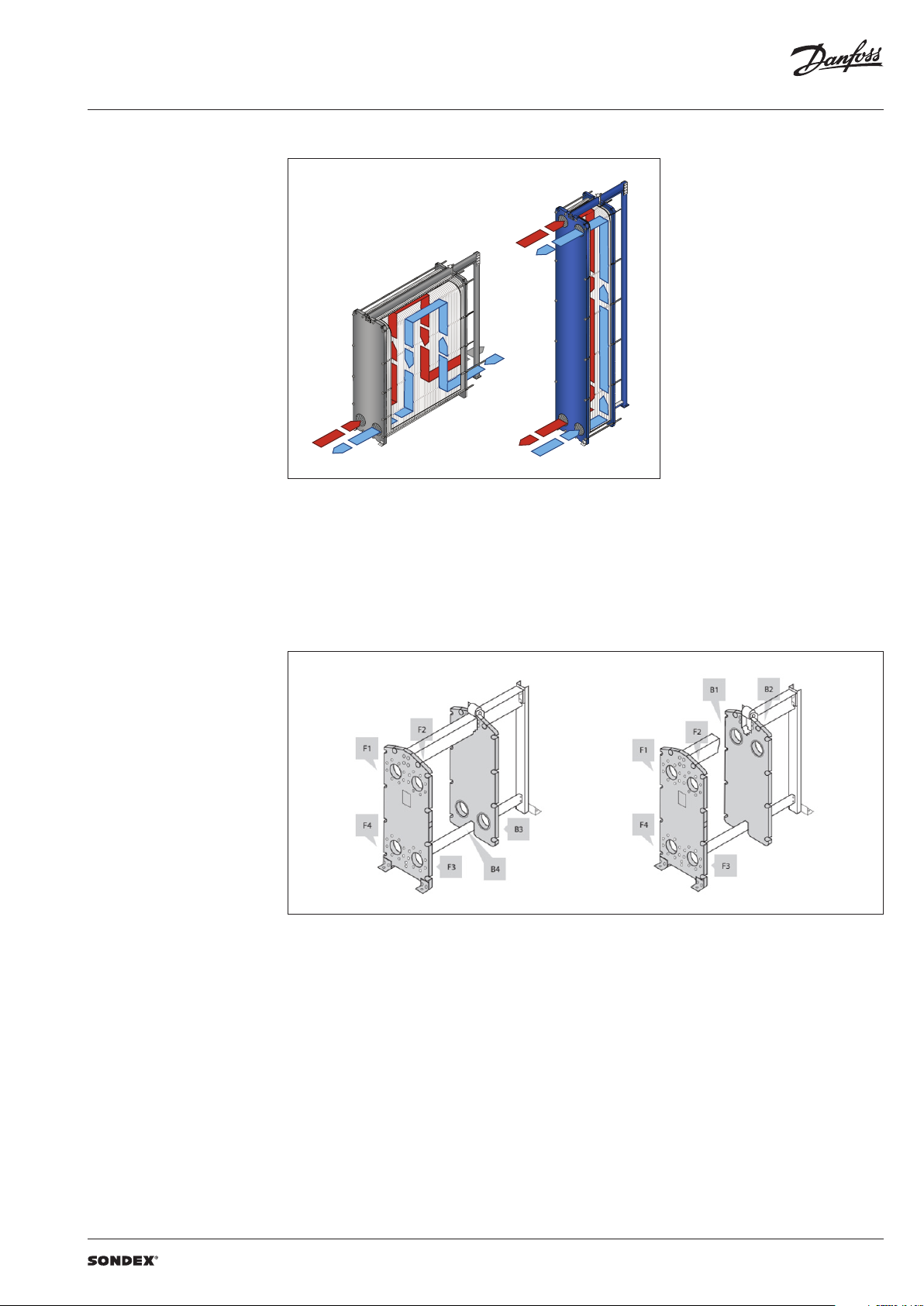
Heat exchanger design
Gasketed heat exchangers consist of
Carrying Bar
Plate Pack
Plate
Connections
Head
Flange Connections
Foundation Feet
Column
Follower
Tie Bolt
Guiding Bar
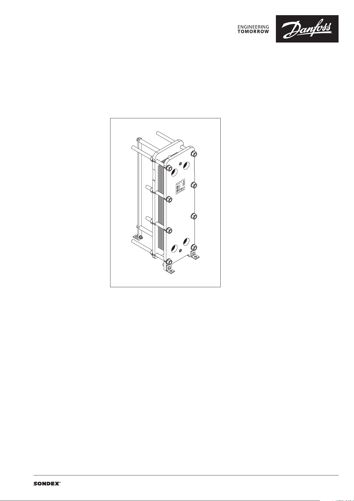
Anatomy of a SONDEX® plate heat exchanger - IS frame.
2 | AI323933698667en-000101 | 2019.11
Data sheet S140 / S201 / S300 (DN 500)
To the left: A multi-pass solution with connections
Heat exchanger design
(continued)
Multi-pass design
on the follower and the head.
To the right: A single-pass solution with
all connections on the head.
Connections
The heat exchanger may have connections on
both front and back-end sides of the unit.
Connections on the front-end plate are marked
with F and connections on the back-end plate
are marked with B. The numbers 1, 2, 3 and 4
designate the position of the connection on the
end-plate from the top-left port clockwise.
AI323933698667en-000101 | 3 | 2019.11

Data sheet S140 / S201 / S300 (DN 500)
SONDEX®
plate
range
Common
Technical data Heat exchanger S140 / S201 / S300
Typ e S140 S201 S300
Max. working pressure
Max. operating temperature
Min. operating temperature -10
Flow medium Water and different fluids, steam
Volume / channel l 5.9 8.8 8.8
Connection size DN 500 / 20”
Connection type
Plate material
Plate thickness mm
Gasket material
Gasket attachment t ype Sonder Lock
Liners in connections
Frame Painted frame, color RAL 5010 (other colors available on request)
Frame painting specification Painting available for corrosion categories C2L, C4M, C5M
1)
Not available f or all frame variations
PN
(bar)
°C
1)
10, (16)
Up to 180
DN 500/20” f langes. Carbon steel, rubberlined or cladded with AISI 316L
(other materials available on request)
Stainless steel EN 1.440 4 (AISI 316L), EN 1.4301 (AISI 304), SMO254, Hastelloy C276,
titanium Gr.1
Other materials available on request
0.5; 0.6; 0.7
Other thicknesses available on request
NBR, EPDM,
Other materials available on request
• Rubber NBR, EPDM,
• Stainless steel EN 1.440 4 (AISI 316L), EN 1.4301 (AISI 304), SMO254, Hastelloy C276,
titanium Gr.1
1)
Using the right plate for each individual duty
is very important, as it greatly impacts the
efficiency of the entire installation.
It is important that the length of the plates and
the type of pattern match the requirements of
individual thermal duty.
We have developed a wide plate portfolio to
provide the perfect plate and connection size for
any duty.
No application is too small or too big for us - we
provide the optimal technical solution every
time.
Our extensive SONDEX® plate portfolio
includes plates that lie outside the commonly
manufactured plate sizes to cover all thermal
duties optimally.
plate
range
4 | AI323933698667en-000101 | 2019.11

Data sheet S140 / S201 / S300 (DN 500)
Accessories Insulation
Recommended applications:
The insulation jacket for the plate heat exchanger
is used in different applications with high
temperatures and cooling systems.
Application Heating Cooling
Material
Outer cap
Internal insulation 0.05 mm aluminium foil
Panel fixation Plastic rivets
Temperature 20 … 200 °C -50 … -80 °C
U-value 0.55 W/m2K 0.3 8 W/m2K
Insulation class 3
Heat loss 17.1 W/m
Please note:
Inlet and outl et temperatures in the exch anger have been based on 9 0/50 – 30/70 °C.
1)
The loss of he ating/cooling is stated per m2 surface on the insu lation jacket.
The bottom o f the heat exchanger is not insu lated and this fact has been e xcluded.
A possible loss of ve ntilation, largely dep endent on the mounting of the h eat exchanger, has not been take n into account either.
Drip trays
Recommended applications:
The drip tray is available in two types. A “failsafe” solution which prevents water or liquid
from leaking onto the floor, or when the
heat exchanger is dismantled, or opened for
inspection and maintenance. And an insulated
drip tray for cooling applications, which
collects condensate formed outside of the plate
heat exchanger.
45 mm mineral wool
Not flammable
DIN EN 4102A2
1)
2
40 mm PU-foam
DIN 4102-1 B2
1 mm aluminium
“Stucco” Embossed
1)
4
-
Materials
Drip tray consists of:
• 1 mm galvanized steel frame
• Hanging brackets in galvanized steel
• 60 mm Polyurethane insulation for cooling
applications
• Draining valve.
Spare parts
Spare parts for gasketed heat exchangers, such
as plates, gaskets, frame parts can be ordered for
maintenance, repair, increasing heat exchanger
capacity, etc.
Selection and ordering Please contact your local SONDEX® or Danfoss
sales representative for the selection and / or
ordering of the heat exchangers, spare parts, and
accessories.
Please contact your local Danfoss or SONDEX®
sales representative to provide you with
information on spare parts available for gasketed
heat exchangers.
For contact information please visit
https://www.danfoss.com/en/contact-us.
AI323933698667en-000101 | 5 | 2019.11
Data sheet S140 / S201 / S300 (DN 500)
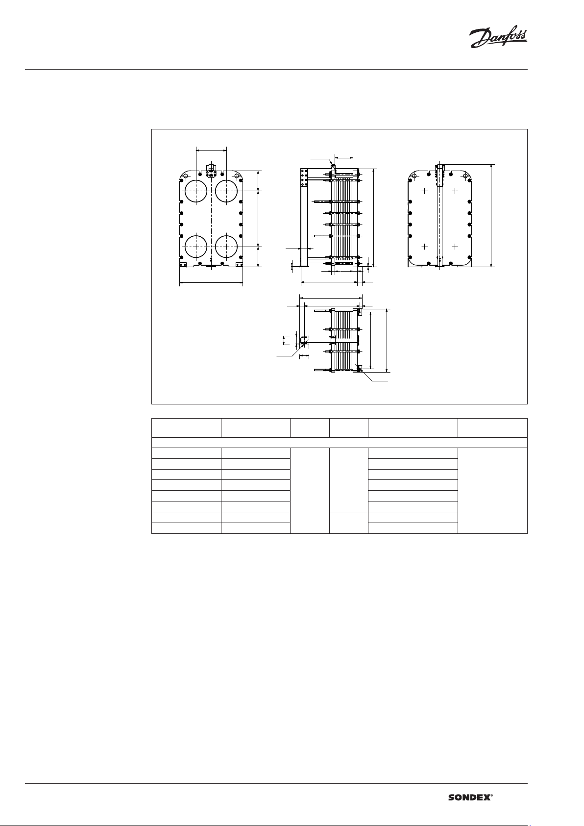
Dimensions
Non-sanitary applications
Any connection can be used for primary side in.
All the rest are made correspondingly.
S140 frames
672
450
F1
F4
F2
F3
450 123 0
W
200
Ø25
150
100
Ø100
20
75
160
200
75
L
L + 125
L − 25
100
L1
B2 B1
H
14
100
50
2175
B3 B4
W
125 0
Ø25
Drawing of S140 IS10 frame
L (frame length)
Number of plates
S140 I S10
7 95 125 0
96 179 1750 7985
180 262 2250 8912
263 345 2750 9839
346 429 3250 10776
430 595 4250 12632
596 762 5250
763 929 6250 16359
1)
the indicate d maximum number of pla tes is based on the minimum plate thi ckness allowable for the PN le vel of the unit;
2)
the maximum w eight of the empty unit with t he maximum allowable nu mber of plates;
1)
(mm)
W
(mm)
140 0
55.12 ”
H
(mm)
2274 ,5
(89.55” )
2524,5
(99.43“ )
Weight max, empt y
(kg)
7048
14495
2)
Connection type
DN 500 flange or 20”
flange
6 | AI323933698667en-000101 | 2019.11

Data sheet S140 / S201 / S300 (DN 500)
Dimensions (continued)
Non-sanitary applications
S201 frames
672
F1
F4
Drawing of S201 IS10 frame
Ø100
L1
450450
B2 B1
F2
1822
H
F3
150
W
20
80
L 100
14
90
B3 B4
14
W
L + 125
100
L − 25
50
Ø25
200
160
200
W
125 0
Ø25
Number of plates
L (frame length)
1)
(mm)
W
(mm)
H
(mm)
Weight max, empt y
(kg)
2)
Connection type
S201 IS10
7 - 95 1240
5883
96 - 178 1740 6996
179 - 261 2240 8113
262 - 345 2740 93 41
346 - 428 324 0 10514
140 0
55.12 ”
2866,5
(112 .8 5” )
DN 500 flange or 20”
429 - 595 424 0 12775
596 - 761 524 0
762 - 928 624 0 17602
3116 ,5
(122 .70 “)
15258
S201 IS16
7 - 90 1260
7278
91 - 173 1760 8460
174 - 256 2260 9642
257 - 340 2760 10837
341 - 423 326 0 12020
1430
(56.30”)
2866,5
112 .8 5”
DN 500 flange or 20”
424 - 590 4260 14398
591 - 756 526 0
757 - 923 6260 1914 0
1)
the indicate d maximum number of pla tes is based on the minimum plate thi ckness allowable for the PN le vel of the unit;
2)
the maximum w eight of the empty unit with t he maximum allowable nu mber of plates;
3116 ,5
(122 .70 “)
16763
flange
flange
AI323933698667en-000101 | 7 | 2019.11

Data sheet S140 / S201 / S300 (DN 500)
Dimensions (continued)
Non-sanitary applications
S300 frames
450
2733
450
Ø 100
L1
450450
B2
F1
F2
672
H
3633
F4
F3
H
3928
150
20
W
80
14
90
100
B1
2733
B3
B4
L + 125
L − 95
Ø25
W
125 0
1000
140
30
940
Ø25
Drawing of S300 IS10 frame
Number of plates
L (frame length)
1)
(mm)
W
(mm)
H
(mm)
Weight max, empt y
(kg)
2)
Connection type
S30 0 IS10
7 - 95 1240
5883
96 - 178 1740 6996
179 - 261 2240 8113
262 - 345 2740 93 41
346 - 428 324 0 10514
140 0
55.12 ”
2866,5
(112 .8 5” )
DN 500 flange or 20”
429 - 595 424 0 12775
596 - 761 524 0
762 - 928 624 0 17602
1)
the indicate d maximum number of pla tes is based on the minimum plate thi ckness allowable for the PN le vel of the unit;
2)
the maximum w eight of the empty unit with t he maximum allowable nu mber of plates;
*)
PN class 16 bar is availa ble on request.
3116 ,5
(122 .70 “)
15258
flange
| DHS-SDBT/SI | 2019.118 | AI323933698667en-000101
 Loading...