

Data sheet
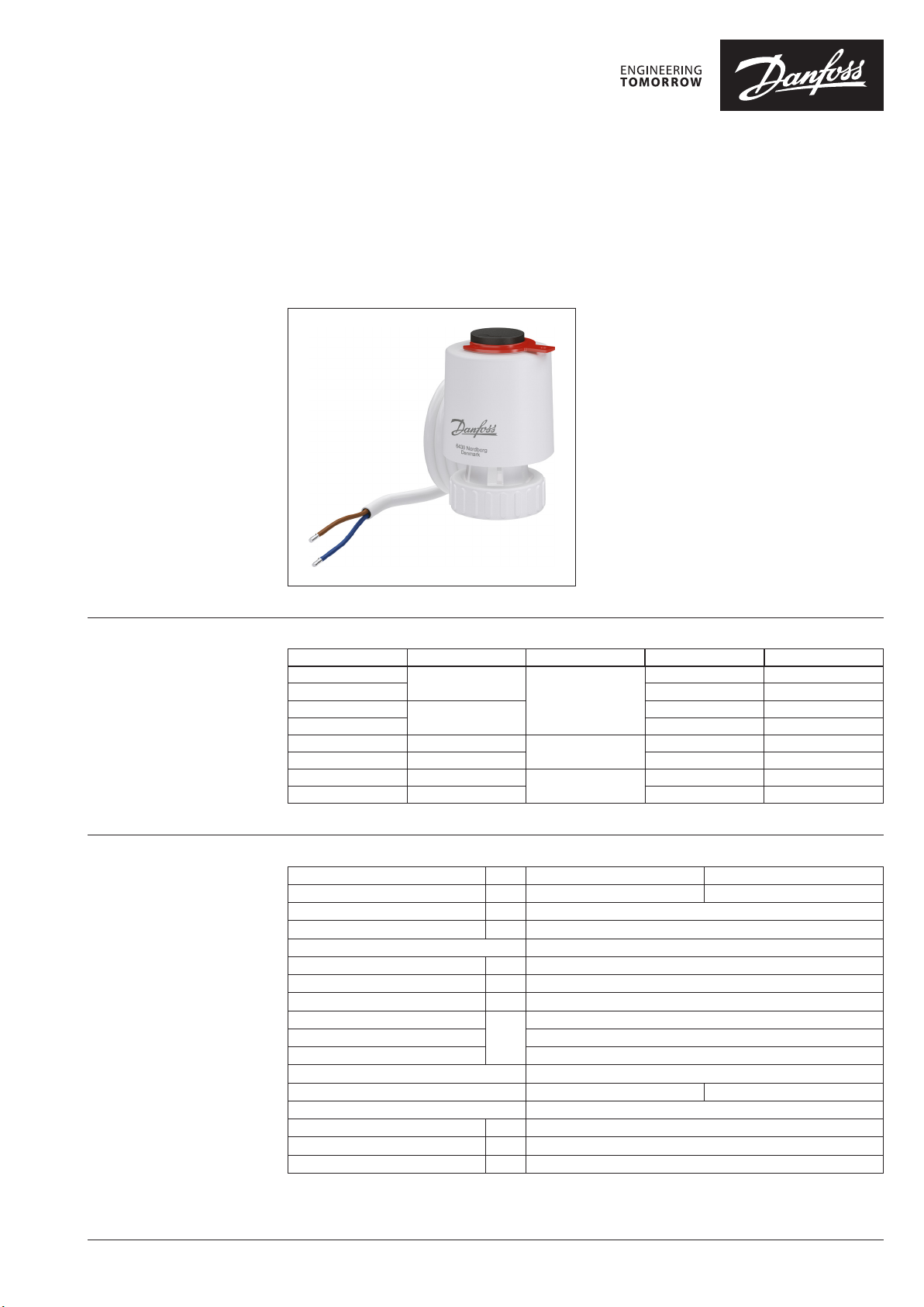
Thermal Actuator TWA-Q
Description
Ordering
Danfoss thermal actuator TWA-Q is used with
Danfoss Pressure Independent Control Valves
(PICV) type AB-QM DN10-32.
The actuator can be controlled with an on/off
controller, pulse width modulation (PWM), or
switch.
These provide a cost effective solution for
the control of hot and /or chilled water for
fan coil units, small reheaters and recoolers in
temperature control systems.
Main features:
• 24 V AC/DC or 230 V AC supply
• Position indicator
• Normally closed (NC) or normally opened
(NO) version
• Max. medium temperature 95 °C
• Cable included, halogen free optional
Typ e Supply voltage Cable length Cable material Code No.
TWA-Q NC
TWA-Q NO PVC 08 2F1601
TWA-Q NC
TWA-Q NO PVC 082F1603
TWA-Q NC 230V AC
TWA-Q NC 24V AC/DC PVC 082 F1605
TWA-Q NC 230V AC
TWA-Q NC 24V AC/DC Halogen free 0 82F 1611
230V AC
1.2 m
24V AC/DC
5 m
2 m
PVC 082 F1600
PVC 082F1602
PVC 082 F1604
Halogen free 082F1610
Technical Data
Power supply V 24 AC/DC, +25%/-20% 230 AC, ± 15%
Max. inrush current A <0.25 (for <60 sec.) <0.25 for (<1 sec.)
Power consumption W < 2
Frequency Hz 50/60
Control input On/off and PWM
Closing force N 110±10
Min. stroke mm 5.0
Full stroke time
Max. medium temperature
Ambient temperature 2 … 60
Storage and transport temperature -40 … 70
Ambient humidity 95% r.h., non-condensing (according to EN 60730-1)
Protection class III II
Grade of enclosure IP 54
Valve connection mm M30 × 1.5
Cable length m 1.2m or 5m PVC or 2m Halogen free
Weight kg 0 .15
1)
at room tempe rature.
1)
min. < 3
95
° C
© Danfoss | 2020.02 AI325956164717en-000101 | 1
Data sheet Thermal Actuator TWA-Q
Operation
TWA-Q actuator works on the thermal expansion
principle:
• moves actuator stem in one direction in case
of heating of the actuator and
• moves actuator stem in another direction in
case of no heating of the actuator
Two versions of actuators are available:
• TWA-Q NC version, in the non-energized state
actuator’s stem is extracted
• TWA-Q NO version, in the non-energized state
actuator’s stem is retracted
Both versions are available in 24V (SELV) or 230V.
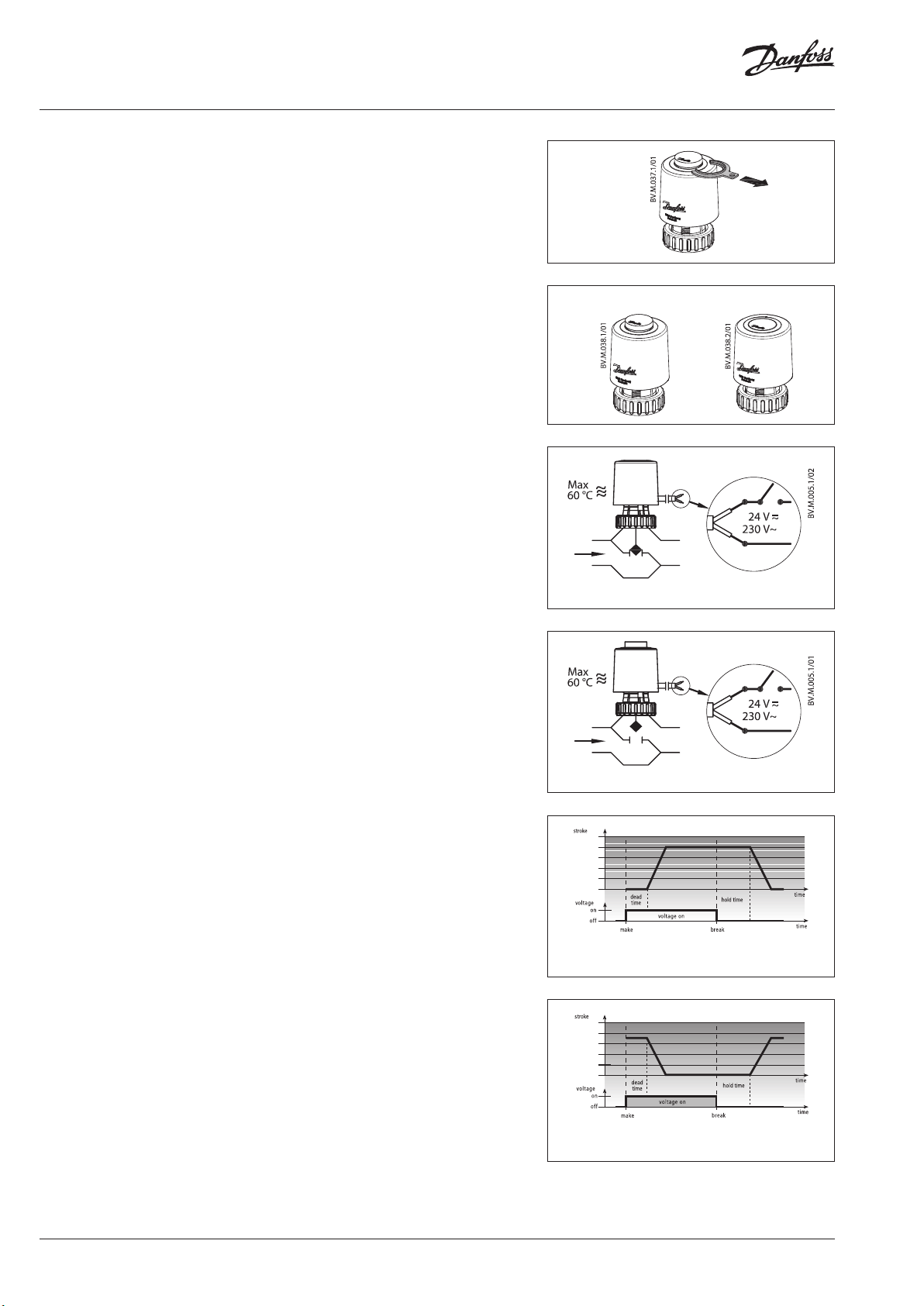
The TWA-Q NC has an internal spring, which is
factory fixed with a split ring (Fig.1) to hold the
spring retracted in its off -the-shelf state.
The use of split ring allows the actuator to be
easy mounted on the valve. Once mounted, the
split ring has to be removed.
Note:
In case the actuator has been dismounted and split
ring removed, split ring can be added back to the
actuator after the heating of the actuator.
The actuator is equipped with a position
indicator to show the position of the actuator
stem (Fig.2).
The AB-QM valve is closed in stem down
position. Without the actuator the force in the
AB-QM internal spring opens the valve.
Fig. 1: NC version
Actuator stem up Actuator stem down
Fig. 2
Blue/Brown
NC
Fig. 3: TWA-Q NC & AB- QM
Combination, TWA-Q NC & AB-QM (Fig.3 & 5)
• in the non-energized state the valve is closed
• in the energized state the valve is open.
The valve starts to open after preheating the
actuator for approx. 1.5 min. if the heating
element is switched on in a cold state (room
temperature), and achieves the maximum stroke
after another approx. 1.5 min. At power-off, the
wax element cools down and the valve will be
closed.
Combination, TWA-Q NO & AB-QM (Fig.4 & 6))
• in the non-energized state the valve is open
• in the energized state the valve is closed
The valve starts to close after preheating the
actuator for approx. 1.5 min. if the heating
element is switched on in a cold state (room
temperature), and closes the valve after another
approx. 1.5 min. At power-off, the wax element
cools down and the valve will be open.
The Thermal Actuator TWA-Q are noise-free and
maintenance-free. When the control signal is
applied to the actuator, the temperature of the
heating element rises, which causes the wax
element to expand, which transfer the stroke to
the installed valve.
Some controllers drive the actuators with a PWM
(Pulse Width Modulation) signal. This improves
the response time.
Blue/Brown
NO
Fig. 4: TWA-Q NO & AB- QM
Fig. 5: TWA-Q NC example of opening curve for the
Normally closed version.
Fig. 6: TWA-Q NO example of opening curve for the
Normally open version.
2 | AI325956164717en-000101 © Danfoss | 2020.02

Data sheet Thermal Actuator TWA-Q
Installation
Actuator / Valve assembly
Mechanical
Installation of the valve with the actuator is
allowed in all positions.
TWA-Q and AB-QM 4.0
(Normally Opened)
NO
IP 54
IP 54
NC
(Normally Closed)
①
IP 54IP 54
③①
Dimensions
67
44
TWA- Q NC
②
②
44
65.5
TWA- Q NO
Disposal The actuator must be dismantled and the
elements sorted into various material groups
before disposal.
AI325956164717en-000101 | 3© Danfoss | 2020.02

Danfos
produc
Al
Danfoss A/S
Heating Segment • heating
Data sheet Thermal Actuator TWA-Q
Tender text
TWA-Q Thermal actuator
On/off therm al actuator used to control pres sure independent bala ncing and control valves DN 10-32.
- Supply Voltage: 24 V AC/D C or 230 V AC, 50/60 Hz.
- Cables: PVC 1.2 m and 5 m. Hal ogen free 1) 2 m.
- Normally Closed or Normally Open variants available.
- First open f unction for the Normall y Closed variant for easy installa tion.
- Visible stroke in dicator.
- Power consumptio n: <2 W, when ac tivated.
1)
halogen fr ee cables available only fo r the Normally Closed variant .
s can accept no responsibility for possible errors in catalogues, brochures and o ther printed material. Danfoss reserves the right to alter its products w ithout notice. This also applies to
ts already on order provided that such alterations can be m ade without subsequential changes being necessary in specications already agreed.
l trademarks in this material are p roperty of the respective companies. Danfoss and a ll Danfoss logotypes are trademarks of Danfoss A/S. All rights reser ved.
.danfoss.com • +45 7488 2222 • E-Mail: heating@danfoss.com
© Danfoss | DHS-SRMT/SI | 2020.024 | AI325956164717en-000101
 Loading...