

Page 1
Data sheet
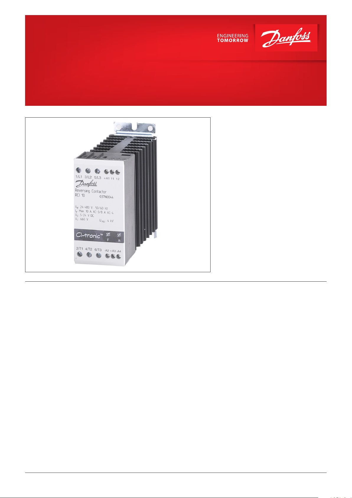
CI-tronic™ Reversing contactor
Type RCI
RCI reversing contactors are designed for
demanding forward/reverse control of
three-phase AC motors. The zero cross
switching method ensures very fast and precise
motor control and virtually eliminates EMC
emission. The RCI reversing contactor is ideal
where fast switching capability and long life are
essential. Typical applications are conveyors,
thread cutting machines, packaging lines and
other applications where fast reversing
capabilities are needed.
Features • Compact modular design complete with
heat sink
• DIN-rail mountable
• Built-in varistor protection
• Operational current up to 10 A (AC-3)
• Line voltage up to 480 V AC
• Built-in interlock
• Universal control voltage
• Burst firing (zero cross)
• LED status indicator
• IP 20 protection
• Problem-free specification according to
industry standard
• Easy and quick installation
• EN 60947-4-2 and UL-C
© Danfoss | DCS (mw) | 2017.10
IC.PD.C50.D3.02 | 520B3036 | 1
Page 2
Data sheet | Reversing contactor, type RCI
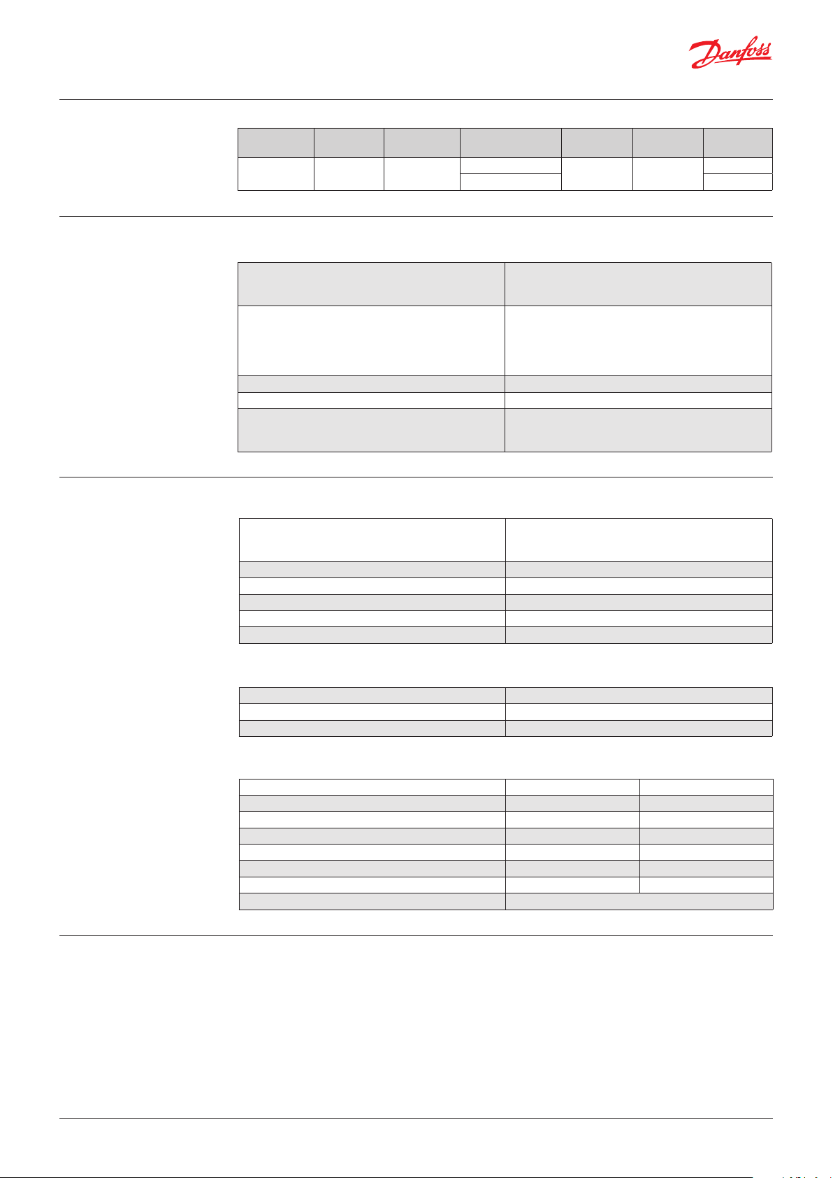
Selection guide
Technical data
Technical data (continued)
Operational
voltage
24 – 480 V AC 10 A 4 kW / 5.5 HP
Max. motor
current
Max. motor
power
Control
voltages
5 – 24 V DC
24 – 230 V AC / DC 037N0043
Dimensions Type Code no.
45 mm
module
RCI 10
Output specifications
Operational current
AC-3 (motor load)
AC 4 (motor load)
Motor size at
208 – 240 V AC (50 / 60 Hz)
400 – 480 V AC (50 / 60 Hz)
Leakage current max. 1 mA
Operational current min. 10 mA
Semiconductor protection fusing
Type 1 coordination
Type 2 coordination
AC-3: 0.1 – 2.2 kW (0.18 – 3 HP)
AC-4: 0.1 – 1.5 kW (0.18 – 2 HP)
AC-3: 0.1 – 4 kW (0.18 – 5.5 HP)
AC-4: 0.1 – 3 kW (0.18 – 4 HP)
10 A
8 A
50 A gL / gG
450 A2s
Thermal specification and environment
Power dissipation
Continuous duty
Intermittend duty
Ambient temperature range −5 °C to 60 °C
Cooling method Neutral convection
Mounting Vertical (± 30°)
Storage temperature range 20 °C to 80 °C
Enclosure degree / pollution degree IP 20/3
2.0 W/A
2.0 W/A x duty cycle
037N0044
Functional description
Insulation
Rated insulation voltage, U
Rated impulse withstand voltage, U
Installation category III
i
imp
660 V AC
4 kV
Control circuit specifications
037N0044 037N0043
Control voltage range (±10%) 5 – 24 V DC 24 – 230 V AC / DC
Pick up voltage max. 4.25 V DC 20.4 V AC / DC
Drop-out voltage min. 1.5 V DC 7.2 V AC / DC
Control current / power max. 25 mA at 4 V DC 6 mA / 1.5 VA at 24 V DC
Response time max. ½ cycle 1 cycle
Interlock delay time (min. / max.) 30 ms / 80 ms 60 ms / 150 ms
EMC immunity Meets requirements of EN 60947-4-2
When control circuit A1 – A2 is ON, the motor will
rotate forward. With control circuit A3 – A4 ON
the motor will rotate in reverse direction. If both
control circuits are switched ON the motor will
rotate in the direction determined by the circuit
which was switched ON first. A delay time
(interlock) between forward and reverse running
is incorporated.
© Danfoss | DCS (mw) | 2017.10
IC.PD.C50.D3.02 | 520B3036 | 2
Page 3

Data sheet | Reversing contactor, type RCI
Functional diagram
Mains voltage (L1, L2, L3)
Control voltage, “F” (A1, A2)
Control voltage, “R” (A3, A4)
Delay F-R
Delay R-F
Motor forward
LED “F”
Motor reverse
LED “R”
Wiring
Motor overload and short
circuit protection
Motor full load current
[A]
Danfoss CTI 25M / CTI 25MB
circuit breaker, code no.
0 – 0.16 047B3140
0.16 – 0.25 047B3141
0.25 – 0.4 047B3142
0.4 – 0.63 047B3143
0.63 – 1.0 047B3144
1.0 – 1.6 047B4145
1.6 – 2.5 047B3153
2.5 – 4.0 047B3154
4.0 – 6.3 047B3155
6.0 – 10.0 047B3156
© Danfoss | DCS (mw) | 2017.10
IC.PD.C50.D3.02 | 520B3036 | 3
Page 4

Data sheet | Reversing contactor, type RCI
Dimensions
Mounting
The controller is designed for vertical mounting.
If the controller is mounted horizontally the load
current must be reduced by 50%. Controllers
mounted side by side need no clearance.
Controllers mounted vertically on top of another
need a clearance of minimum 80 mm (3.15 in.).
Clearance between controller top and “ceiling”
and between controller bottom and “floor” must
be at least 30 mm (1.2 in.)
© Danfoss | DCS (mw) | 2017.10
IC.PD.C50.D3.02 | 520B3036 | 4
Page 5

Danfoss can accept no responsibility for possible errors in catalogues, brochures and other printed material. Danfoss reserves the right to alter its products without notice. This also applies to products
already on order provided that such alterations can be made without subsequential changes being necessary eady agreed.
All trademarks in this material are property of the respective companies. Danfoss and the Danfoss logotype are trademarks of Danfoss A/S. All rights reserved.
Overheat protection
If required the controller can be protected
against overheating by inserting a thermostat in
the slot on the right-hand side of the controller.
Order: UP 62 thermostat 037N0050
The thermostat is connected in series with the
control circuit of the main contactor.
When the temperature of the heat sink exceeds
100 °C the main contactor will be swtiched OFF.
A manual reset is necessary to restart this circuit.
For wiring connections see application
examples.
Application examples
Combined reversing contactor and soft starter
Soft start & soft stop
A soft reversing of a motor can easily be achieved
by connecting a reversing contactor to the soft
starter.
The reversing contactor, type RCI, will determine
the direction of rotation, forward or reverse and
the soft starter, type MCI, will perform soft
starting and soft stopping of a motor.
Soft start only
If soft stop is not required, the application can be
simplified by connecting the control circuit of the
soft starter to the main terminals.
A delay of approx. 0.5 sec. between forward and
reverse control signal must be allowed to avoid
influence from the voltage generated by the
motor during turn-off.
© Danfoss | DCS (mw) | 2017.10
IC.PD.C50.D3.02 | 520B3036 | 5
 Loading...