

Page 1
Data sheet
Valves for Control of Fan Coils and Terminal Units
RA‑HC
Description
The RA-HC is a control valve applied together with
Danfoss self-acting or Danfoss electronic controls in
fan coil units and similar terminal units in any HVAC
system. When installed with Danfoss ASV, balancing
and control functions are combined representing the
complete dynamic hydraulic solution.
Combined with Danfoss thermo actuators (TWA) the
RA-HC valves provide On/Off control, control the
flow over the terminal unit and maintain optimum
temperatures based on room load requirements.
RA-HC valves have eight presettings, thus the correct
quantity of water flow is ensured for each circuit.
Ordering and Specification RA‑HC valve
Connection
Typ e
DN 15 G ⁄ yes 16 1.8 −10 … 100 003Z3931
DN 20 G ⁄ yes 16 1.8 −10 … 100 003Z3910
DN 25 G 1 yes 16 1. 8 −10 … 100 003Z3911
DN 15 G ⁄ no 16 1.8 −10 … 100 003Z3932
DN 20 G ⁄ no 16 1. 8 −10 … 100 003Z3920
DN 25 G 1 no 16 1.8 −10 … 100 003Z3921
The max. di fferential pressure spe cified is the maximum pre ssure at which the valves give satisfac tory regulation. As wi th any device
which imposes a p ressure drop on the system, no ise may occur under certain f low/pressure conditions.
RA‑HC accessories
Typ e
TWA-A NC
TWA-A NO 08 8H 3111
TWA-A NC
TWA-A NO 088H3113
Manual shut off knob - 013 G330 0
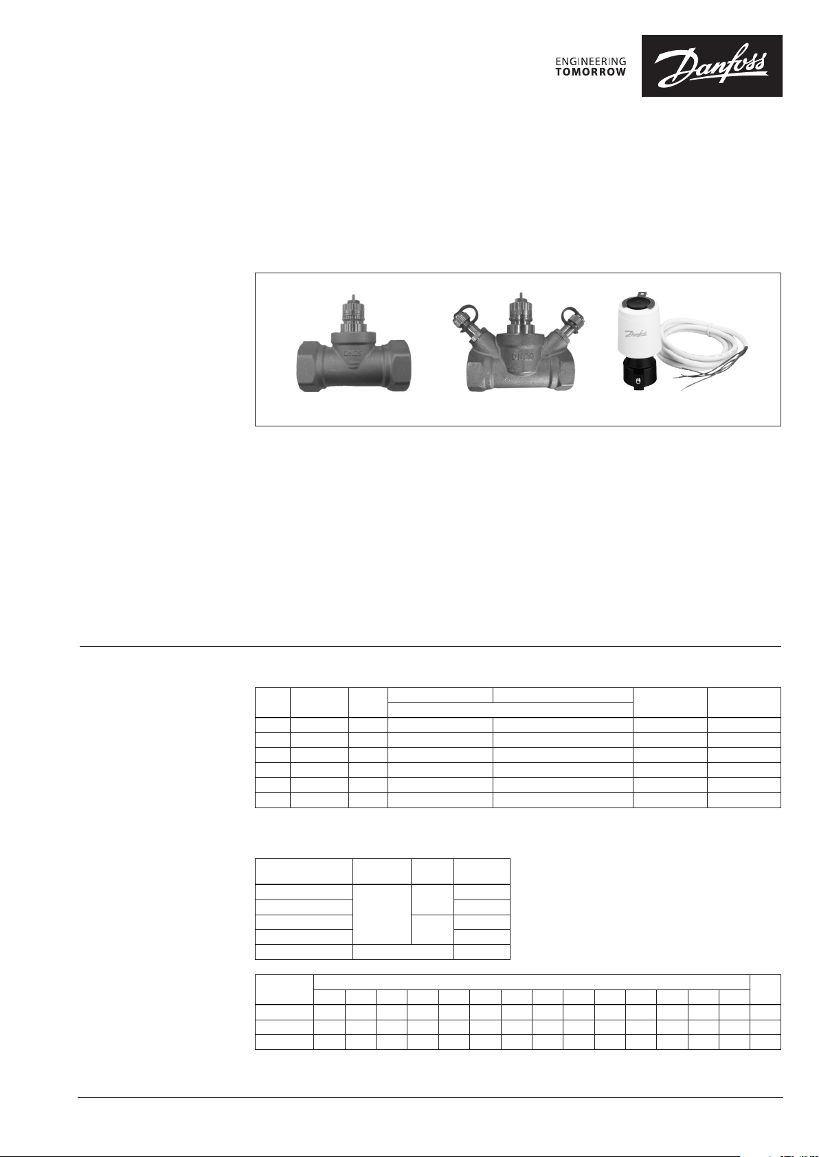
RA‑HC
without test plugs
Tes t
plugs
(“)
Connection
type
RA
RA‑HC
TWA ‑A
with test plugs
RA-HC matches high flow capacities and with its
compact design only little installation space is
required.
The RA-HC with TWA and ASV provide:
• Balancing and control function
• High flow capacity
• Compact design, requires small installation space
• Easy presetting, no tools required
• Measuring on ASV partner valve or optional on
RA-HC
• Shut-off (for isolation during system maintenance)
using manual shut off knob.
Max working pressure Max dif f. Pressure with TWA‑A Medium Temp
bar
Supply
Voltage
AC/DC
24 V
230 V
AC
Code No.
088H3110
088H3112
(°C)
Code No.
© Danfoss | 2020.02
Valve
DN 15 0.11 0.16 0.22 0.28 0.41 0.62 0.82 1.0 1.2 1.3 1.5 1.7 2.0 2.8 2.8
DN 20 0.29 0.34 0.43 0.68 0.88 1.1 1. 3 1.4 1.7 2.2 2.8 3.1 3.3 4.3 4.3
DN 25 0.35 0.41 0.58 0.79 1.0 1. 3 1.5 1.7 2.2 2.9 3.7 3.9 4.0 5.5 5.5
1)
The kv‑values show the f low (Q) in m3/h at a diffe rential pressure (∆p) of 1 bar throu gh the valve.
1 1.5 2 2.5 3 3.5 4 4.5 5 5.5 6 6.5 7 N
Presettings, kv values
1)
AI175386404642en-000502 | 1
k
VS
Page 2
Data sheet RA‑HC Valves for Control of Fan Coils and Terminal Units
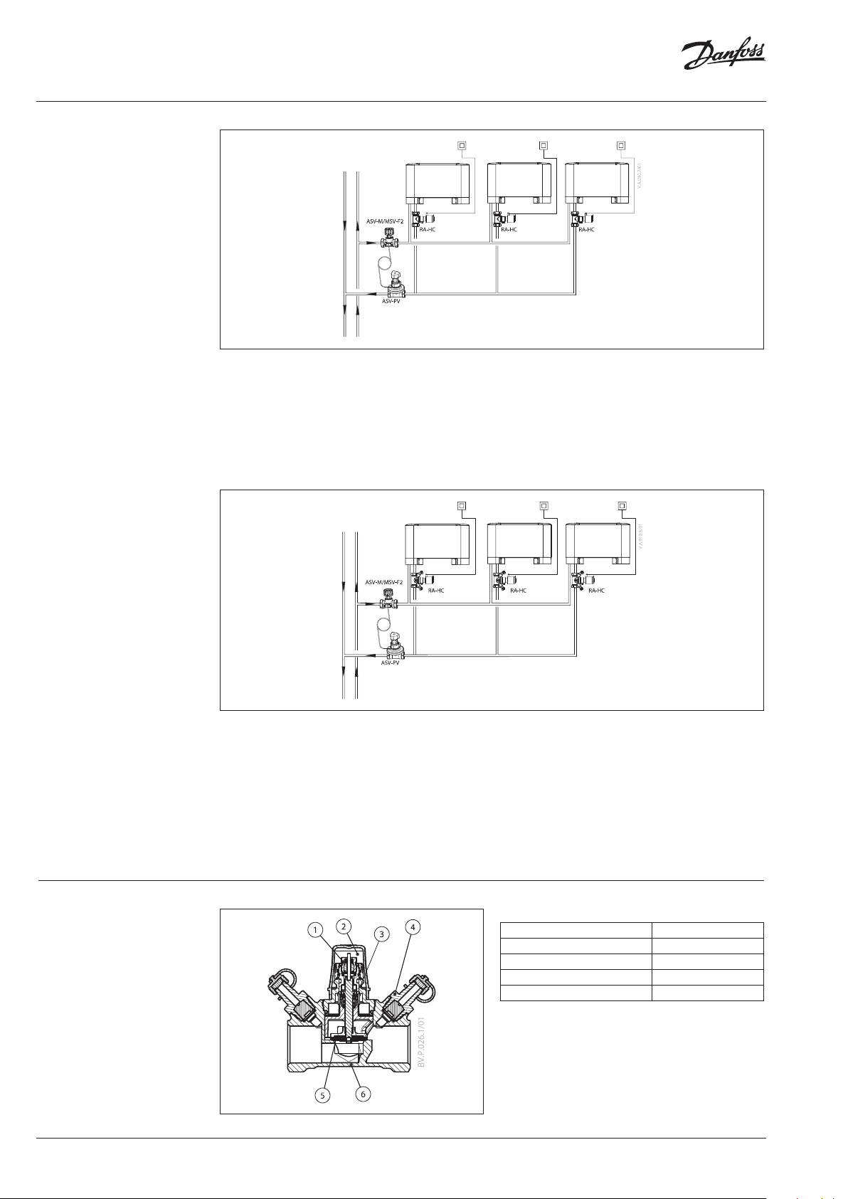
System and Flow
Verification
For RA-HC without test plugs, it is recommended to
do measuring and flow verification with Danfoss PFM
5001 or Danfoss flow indicator on the ASV-PV partner
valve.
For ASV-PV < DN 50 the recommended partner
valve is ASV-I or ASV-BD. For ASV-PV > DN 50 the
recommended partner valve is MSV-F2.
For RA-HC with test plugs, it is accepted to do
measuring and flow verification with Danfoss PFM
5001 or Danfoss flow indicator on the RA-HC valve
directly.
For ASV-PV < DN 50 the recommended partner valve
is ASV-M or ASV-BD.
For ASV-PV > DN 50 the recommended partner valve
is MSV-F2.
For detailed information on:
• ASV-PV data sheet
• PFM 5001 data sheet
• Flow indicator data sheet
For detailed information on:
• ASV-PV data sheet
• PFM 5001 data sheet
• Flow indicator data sheet
Design
1. Gland seal
2. Protection cap
3. Valve head
4. Test plugs
5. Sealing pad
6. Valve body
2 | AI175386404642en-000502
Materials in contact with flow medium
Valve body and other metal par ts DZR
Cone DZR
O-rings EPDM
Sealing pad NBR
kv-setting ring Ryton PPS
1)
Flow medium: water and water mixture s with secondary
coolants like gl ycols (regarding suitability an d usage especially
in not oxyge n tight systems please see the ins tructions given by
the coolant pro ducer) .
1)
© Danfoss | 2020.02
Page 3

Data sheet RA‑HC Valves for Control of Fan Coils and Terminal Units
Capacities
RA‑HC DN 15
© Danfoss | 2020.02
RA‑HC DN 20
RA‑HC DN 25
AI175386404642en-000502 | 3
Page 4

Data sheet RA‑HC Valves for Control of Fan Coils and Terminal Units
Presetting The calculated setting can be set easily and exactly
without using special tools:
• remove the protective cap or sensor element
• raise the setting ring
• turn the scale on the setting ring (anticlockwise)
until the required scale value faces the reference
mark *
• release the setting ring
* wthe fac tory setting of the val ve is N.
The presetting can be set at the values: 1-7 and N. At
setting N, the valve is completely open.
A setting in the shaded areas should be avoided.
When the sensor element is mounted, the presetting
is hidden, and is thus protected against alteration.
Settin g N = open valve
Presetting range
Pressure and Noise
Conditions
Dimensions
Special demands are made on the various
components of the system. This is due to water
temperature conditions, the chosen pipe types and
pipe dimensions of fancoils/induction units and the
structure of the cooling circuits.
In chilled ceilings and fancoils/induction-units
relatively large differential pressure and water flow are
often used compared to normal heating systems. This
may lead to noise nuisance.
1
H
D
S
L
1
Typ e Code no.
DN 15 003Z3931 G ⁄ 81 108 65.5 107 27
DN 20 003Z3910 G ⁄ 81 106 66 107 32
DN 25 003Z3911 G 1 91 112 66 107 41
DN 15 003Z3932 G ⁄ 81 - 65.5 107 27
DN 20 003Z3920
DN 25 003Z3921 G 1 91 - 66 107 41
1
H
S
D L
(inch) mm
G ⁄
The RA-HC valve has especially been designed to
correspond to these demands, no matter whether
self-acting or electronic controls are used.
L
2
2
H
D
L
1
L
1
81 - 66 107 32
H
2
H
1
S
2
4 | AI175386404642en-000502
© Danfoss | DHS-SRMT/SI | 2020.02
 Loading...