

Page 1
OperatingGuide
ECLComfort310,applicationP348
1.0TableofContents
1.0TableofContents...............................................1
1.1Importantsafetyandproductinformation.....................2
2.0Installation........................................................6
2.1Beforeyoustart.....................................................6
2.2Identifyingthesystemtype......................................12
2.3Mounting...........................................................13
2.4Placingthetemperaturesensors................................17
2.5Electricalconnections.............................................19
2.6InsertingtheECLApplicationKey..............................26
2.7Checklist............................................................32
2.8Navigation,ECLApplicationKeyP348.........................33
3.0Dailyuse.........................................................38
3.1Howtonavigate...................................................38
3.2Understandingthecontrollerdisplay..........................39
3.3Ageneraloverview:Whatdothesymbolsmean?...........43
3.4Monitoringtemperaturesandsystem
components........................................................44
3.5Influenceoverview................................................45
3.6Manualcontrol.....................................................46
3.7Schedule............................................................47
4.0Settingsoverview............................................48
5.0Settings...........................................................51
5.1IntroductiontoSettings..........................................51
5.2Flowtemperature..................................................52
5.3Roomlimit..........................................................55
5.4Returnlimit.........................................................58
5.5Flow/powerlimit.................................................64
5.6Optimization........................................................68
5.7Controlparameters................................................74
5.8Flowmeter..........................................................80
5.9Application.........................................................82
5.10Heatcut-out........................................................90
5.11Tanktemperature..................................................93
5.12Anti-bacteria........................................................96
5.13Alarm................................................................98
5.14Alarmoverview..................................................102
6.0Commoncontrollersettings............................103
6.1Introductionto‘Commoncontrollersettings’..............103
6.2Time&Date.......................................................104
6.3Inputoverview...................................................105
6.4Log.................................................................106
6.5Outputoverride..................................................107
6.6Keyfunctions.....................................................108
6.7System.............................................................110
7.0Miscellaneous................................................117
7.1ECA30/31setupprocedures.................................117
7.2Overridefunction................................................125
7.3Severalcontrollersinthesamesystem......................128
7.4Frequentlyaskedquestions....................................131
7.5Definitions........................................................133
7.6Type(ID6001),overview.......................................137
7.7ParameterIDoverview..........................................138
©Danfoss|2018.11VI.LV.G3.02|1
Page 2

OperatingGuideECLComfort310,applicationP348
1.1Importantsafetyandproductinformation
1.1.1Importantsafetyandproductinformation
ThisOperatingGuideisassociatedwiththeECLApplicationKey
P348(codeno.087H3843).
TheECLApplicationKeyP348containsonesubtype,P348.1,
whichisaheatingandanadvancedDomesticHotWater(DHW)
application.
SeetheInstallationGuideforelectricalconnections.
DescribedfunctionsarerealizedinECLComfort310whichalso
allowsM-bus,ModbusandEthernet(Internet)communication.
TheApplicationKeyP348complieswithECLComfort310
controllersasoffirmwareversion1.11.Thefirmware(controller
software)isvisibleatstart-upofthecontrollerandin'Common
controllersettings'in'System'.
UptotwoRemoteControlUnits,ECA30orECA31,canbe
connected.
TheapplicationP348workswithadditionalInternalI/Omodules:
•TheextensionmoduleECA32gives0-10Voltsignalforspeed
controlofDHWrelatedchargingandcirculationpump.
•TheextensionmoduleECA35gives0-10Voltsignalforspeed
controlofDHWrelatedchargingandcirculationpump.ECA35
canalsogivePWM*signalforspeedcontrolofthelistedpumps.
Acirculationpumpcanbeconsideredasacirculatortoo.
TheECLComfort310workswitheitheroneECA32oroneECA
35.TheInternalI/Omoduleinquestionisplacedinthebasepart
oftheECLComfort310.
*PWM=PulseWidthModulation
TogetherwiththeECLComfort310theadditionalInternalI/O
modulescanalsobeusedforextradatacommunicationtoSCADA:
•Temperature,Pt1000(default)
•0-10voltsignals
•Digitalinput
Theset-upofinputtypecanbedonebymeansoftheDanfoss
Software"ECLTool".
Navigation:Danfoss.com>Products&Solutions>Products>
DistrictHeatingandCooling>Documentation>Tools&Software
>ECLTool.
TheURLis:
https://www.danfoss.com/en/service-and-support/downloads
ECLComfort310isavailableas:
•ECLComfort310,230volta.c.(codeno.087H3040)
•ECLComfort310B,230volta.c.(codeno.087H3050)
•ECLComfort310,24volta.c.(codeno.087H3044)
TheB-typehasnodisplayanddial.
2|©Danfoss|2018.11
VI.LV.G3.02
Page 3
OperatingGuideECLComfort310,applicationP348
TheB-typeisoperatedbymeansoftheremotecontrolunit
ECA30/31:
•ECA30(codeno.087H3200)
•ECA31(codeno.087H3201)
InternalI/Omodules:
•ECA32(codeno.087H3202)
•ECA35(codeno.087H3205)
BasepartforECLComfort310,230voltand24volt:Codeno.
087H3230.
AdditionaldocumentationforECLComfort210and310,modules
andaccessoriesisavailableonhttp://heating.danfoss.com/.
SafetyNote
Toavoidinjuryofpersonsanddamagestothedevice,itisabsolutely
necessarytoreadandobservetheseinstructionscarefully.
Necessaryassembly,start-up,andmaintenanceworkmustbe
performedbyqualifiedandauthorizedpersonnelonly.
Locallegislationsmustberespected.Thiscomprisesalsocable
dimensionsandtypeofisolation(doubleisolatedat230V).
AfusefortheECLComfortinstallationismax.10Atypically.
TheambienttemperaturerangesforECLComfortinoperationare:
ECLComfort210/310:0-55°C
ECLComfort296:0-45°C.
Exceedingthetemperaturerangecanresultinmalfunctions.
Installationmustbeavoidedifthereisariskforcondensation(dew).
Thewarningsignisusedtoemphasizespecialconditionsthatshould
betakenintoconsideration.
Thissymbolindicatesthatthisparticularpieceofinformationshould
bereadwithspecialattention.
Applicationkeysmightbereleasedbeforealldisplaytextsare
translated.InthiscasethetextisinEnglish.
VI.LV.G3.02
©Danfoss|2018.11|3
Page 4

OperatingGuideECLComfort310,applicationP348
Automaticupdateofcontrollersoftware(firmware):
Thesoftwareofthecontrollerisupdatedautomaticallywhenthekey
isinserted(asofcontrollerversion1.11(ECL210/310)andversion
1.58(ECL296)).Thefollowinganimationwillbeshownwhenthe
softwareisbeingupdated:
Progressbar
Duringupdate:
•DonotremovetheKEY
Ifthekeyisremovedbeforethehour-glassisshown,youhave
tostartafresh.
•Donotdisconnectthepower
Ifthepowerisinterruptedwhenthehour-glassisshown,the
controllerwillnotwork.
•Manualupdateofcontrollersoftware(firmware):
Seethesection"Automatic/manualupdateoffirmware"
AsthisOperatingGuidecoversseveralsystemtypes,specialsystem
settingswillbemarkedwithasystemtype.Allsystemtypesareshown
inthechapter:'Identifyingyoursystemtype'.
°C(degreesCelsius)isameasuredtemperaturevaluewhereasK
(Kelvin)oftenisusedfortemperaturedifferences.
TheIDno.isuniquefortheselectedparameter.
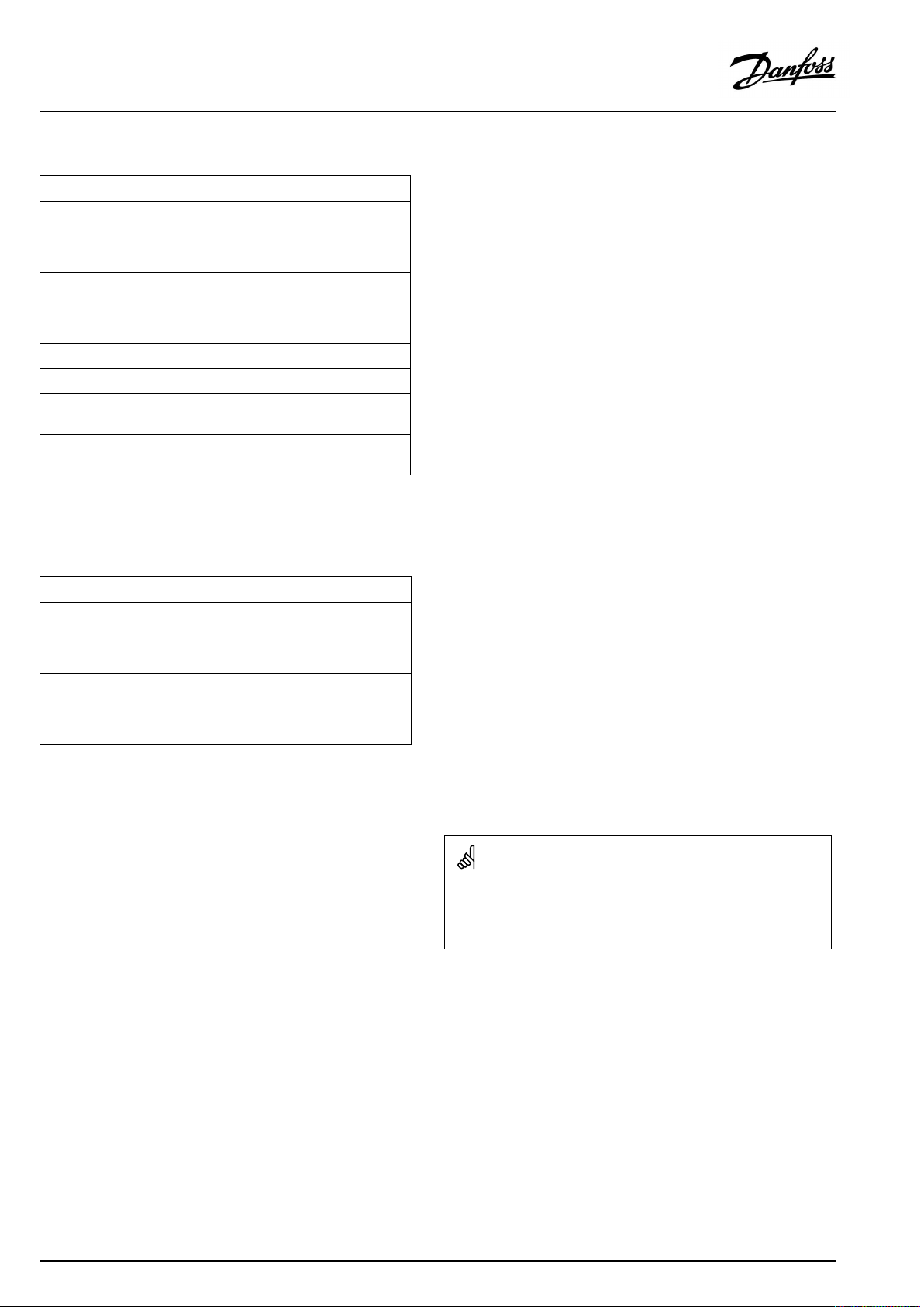
ExampleFirstdigitSeconddigitLastthreedigits
1117411174
-
12174
IfanIDdescriptionismentionedmorethanonce,itmeansthatthere
arespecialsettingsforoneormoresystemtypes.Itwillbemarked
withthesystemtypeinquestion(e.g.12174-A266.9).
1
-
Circuit1Parameterno.
2
Circuit2Parameterno.
174
4|©Danfoss|2018.11
VI.LV.G3.02
Page 5

OperatingGuideECLComfort310,applicationP348
ParametersindicatedwithanIDno.like"1x607"meanauniversal
parameter.
xstandsforcircuit/parametergroup.
DisposalNote
Thisproductshouldbedismantledanditscomponents
sorted,ifpossible,invariousgroupsbeforerecycling
ordisposal.
Alwaysfollowthelocaldisposalregulations.
VI.LV.G3.02
©Danfoss|2018.11|5
Page 6
OperatingGuideECLComfort310,applicationP348
2.0Installation
2.1Beforeyoustart
TheECLapplicationkeyP348containsonesubtype,P348.1.
Thisapplicationforheatingtemperaturecontrolandadvanced
DHWtemperaturecontrolisveryflexible.
Theheatingcircuit:
P348.1,ex.ashowstworadiatorcircuitsinparallel,eachcircuit
withitsownreturntemperaturesensorformonitoringpurpose.
P348.1,ex.bshowsoneradiatorcircuitwithitsownreturn
temperaturesensorformonitoringpurpose.
P348.1,ex.cshowstworadiatorcircuitsinparallel,eachcircuit
withitsownreturntemperaturesensorformonitoringpurpose.
P348.1,ex.dshowsoneradiatorcircuitwithitsownreturn
temperaturesensorformonitoringpurpose.
Temperaturecontrolofheatingcircuit:
Theflowtemperatureisadjustedaccordingtoyourrequirements.
TheflowtemperaturesensorS3isthemostimportantsensorand
mustbeconnected.DesiredflowtemperatureatS3iscalculated
intheECLcontroller,basedontheoutdoortemperatureS1and
thedesiredroomtemperature.
Ingeneral,thelowertheoutdoortemperature,thehigherthe
desiredflowtemperature.
Bymeansofaweekschedule,theheatingcircuitcanbein‘Comfort’
or‘Saving’mode(twovaluesforthedesiredroomtemperature).In
Savingmodetheheatingcanbereducedorswitchedofftotally.
ThemotorizedcontrolvalveM2isopenedgraduallywhenthe
flowtemperatureislowerthanthedesiredflowtemperatureand
viceversa.
ThereturntemperatureS5canbelimited,forexamplenottobe
toohigh.Ifso,thedesiredflowtemperatureatS3canbeadjusted
(typicallytoalowervalue),whichresultsinagradualclosingof
themotorizedcontrolvalve.Furthermore,thereturntemperature
limitationcanbedependentontheoutdoortemperature.
Typically,thelowertheoutdoortemperature,thehigherthe
acceptedreturntemperature.
Inboiler-basedheatingsupplythereturntemperatureshouldnot
betoolow(sameadjustmentprocedureasabove).
Ifthemeasuredroomtemperature(viaECA30/31)doesnotequal
thedesiredroomtemperature,thedesiredflowtemperaturecan
beadjusted.
Thecirculationpump,P2,isONatheatdemandoratfrost
protection.
TheheatingcanbeswitchedOFFwhentheoutdoortemperatureis
higherthanaselectablevalue.
ReturntemperaturesensorsS11andS12areusedformonitoring
purposeonly.
PressuresensorsS15andS16areusedformonitoringpurpose.
Furthermore,analarmcanbeactivatedifthepressuregetshigher
thanasetvalueorlowerthananothersetvalue.
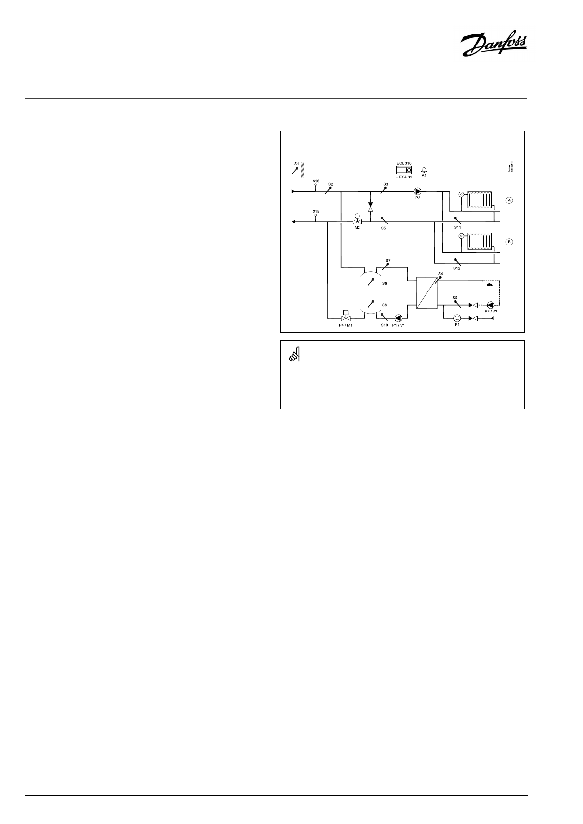
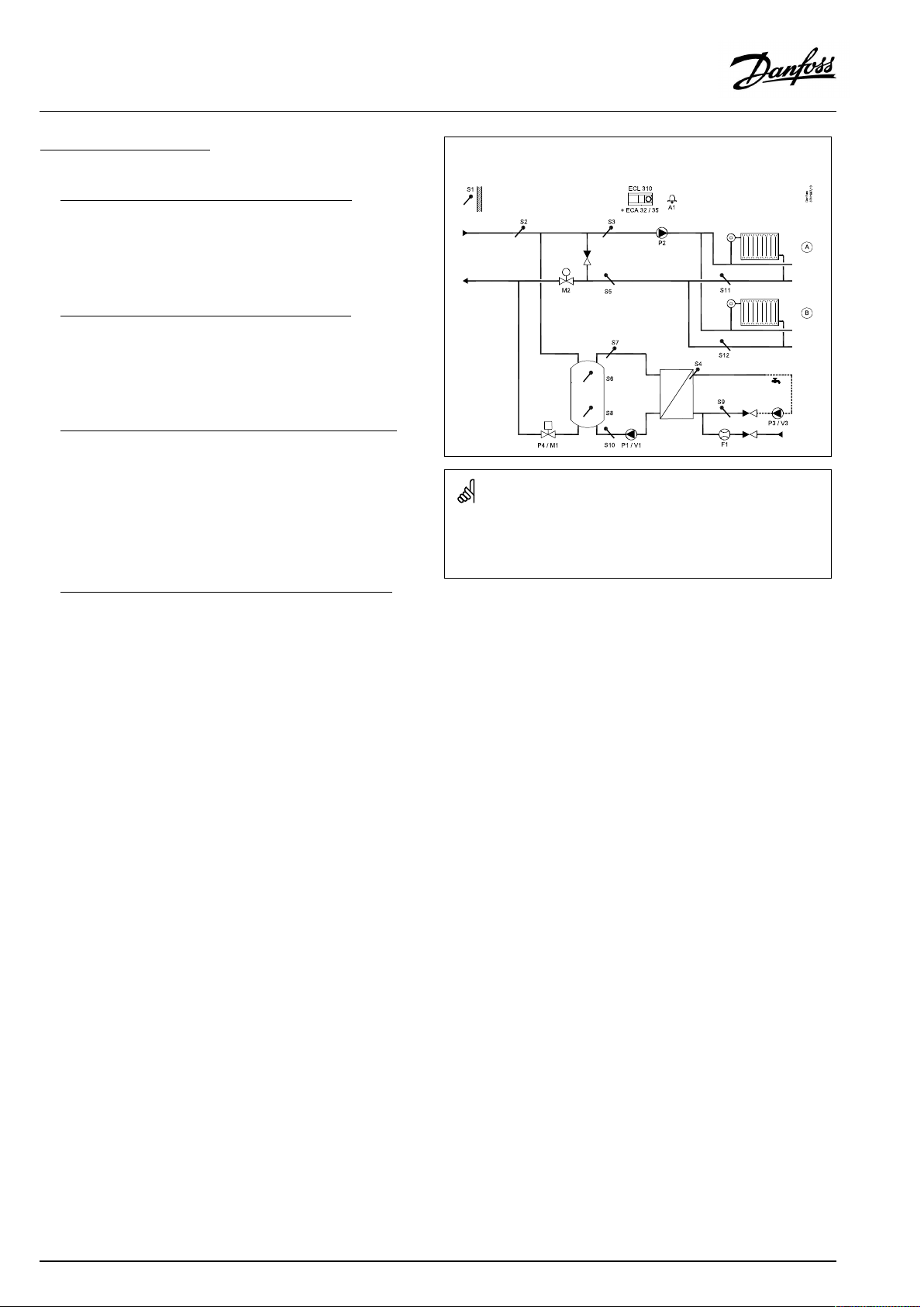
P348.1,ex.a,heating(circuitsAandB)andDHWtemperaturecontrol.
PumpsinDHWcircuitcanbe0–10Voltcontrolled.
Theshowndiagramisafundamentalandsimplifiedexampleanddoes
notcontainallcomponentsthatarenecessaryinasystem.
AllnamedcomponentsareconnectedtotheECLComfortcontroller.
Listofcomponents:
ECL310
ECA32
S1
S2
S3
S4
S5Returntemperaturesensor,circuit1
S6
S7
S8
S9
S10
S11Returntemperaturesensor,circuit1A
S12Returntemperaturesensor,circuit1B
S15
S16
F1
P1
V1
P2
P3
V3
M1
M2
A1
ECLComfort310controller
Built-inextensionmodule,0-10Voutputsfor
pumpspeedcontrol
Outdoortemperaturesensor
Supplytemperaturesensor
(mandatory)Flowtemperaturesensor,circuit1
(mandatory)DHWflowtemperaturesensor,circuit
2
(mandatory)Upperbuffertemperaturesensor
Bufferflowtemperaturesensor
Lowerbuffertemperaturesensor
DHWcirculationreturntemperaturesensor
Bufferreturntemperaturesensor
Supplyreturnpressuresensor
Supplyflowpressuresensor
Flowmeter(signaltype:Pulse)
DHWbufferchargingpump(ON-OFFcontrolled)
SpeedcontrolofDHWbufferchargingpump(0-
10V)
Circulationpump(ON-OFFcontrolled),circuit1
DHWcirculationpump(ON-OFFcontrolled)
SpeedcontrolofDHWcirculationpump(0-10V)
Motorizedcontrolvalve(ON-OFFcontrolled)
Motorizedcontrolvalve(3-pointcontrolled)
Alarm
6|©Danfoss|2018.11
VI.LV.G3.02
Page 7
OperatingGuideECLComfort310,applicationP348
AconnectedfloworenergymeterbasedonM-bussignalcanlimit
thefloworenergytoasetmaximumvalue.Furthermore,the
limitationcanbeinrelationtotheoutdoortemperature.Typically,
thelowertheoutdoortemperature,thehighertheacceptedflow/
power.
Thefrostprotectionmodemaintainsaselectableflowtemperature,
forexample10°C.
TheheatingcircuitcanactasmasterandviatheECL485
communicationbusfulfiltheheatdemandfromslavecircuits.
Exerciseofcirculationpumpandcontrolvalveinperiodswithout
heatingdemandcanbearranged.
TheDHW(DomesticHotWater)circuit:
P348.1,ex.aandP348.1,ex.brunwiththeextensionmodule
ECA32only.Thisallowsforspeedcontrolbymeansofvoltage
signalofchargingpumpP1/V1andcirculationpumpP3/V3.
P348.1,ex.candP348.1,ex.dcanrunwiththeextension
moduleECA32(speedcontrol(bymeansofvoltagesignal)ofthe
pumpsP1/V1andP3/V3)—orrunwiththeextensionmodule
ECA35forspeedcontrol(bymeansofvoltageorPWMsignal)of
thepumpsP1/V1andP3/V3.
Temperaturecontrolofbuffer:
ThedesiredDHWtemperatureatS4determinesthebuffer
chargingprocedure.TheDHWtemperaturesensorS4andupper
buffertemperaturesensorS6arethemostimportantsensorsand
mustbeconnected.
ThedesiredbuffertemperatureatS6isbasedonthedesired
DHWtemperatureatS4andaset"Demandoffset"(=Charging
difference).
P4hasanON/OFFfunction.M1followsP4tobeeitherfullyopen
orfullyclosed.
Startbufferchargingprocess:
1.BuffertemperatureS6temperaturegetslowerthan('Desired
DHWtemperature'+'Demandoffset'+'Startdiff. ').
Anexample:60°C+6K+(-2K)=64°C
2.P4isswitchedON;M1iscommandedtoopen
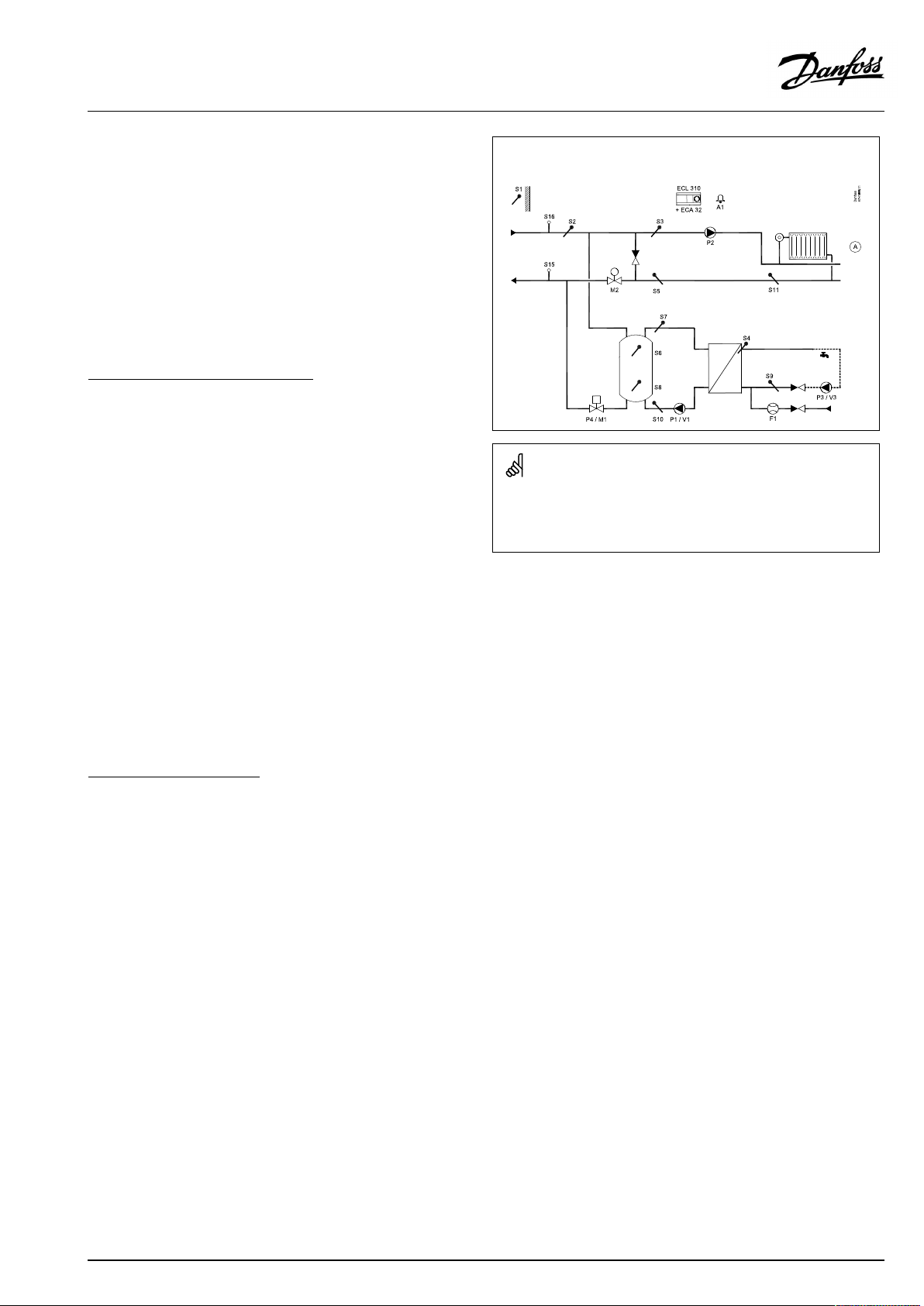
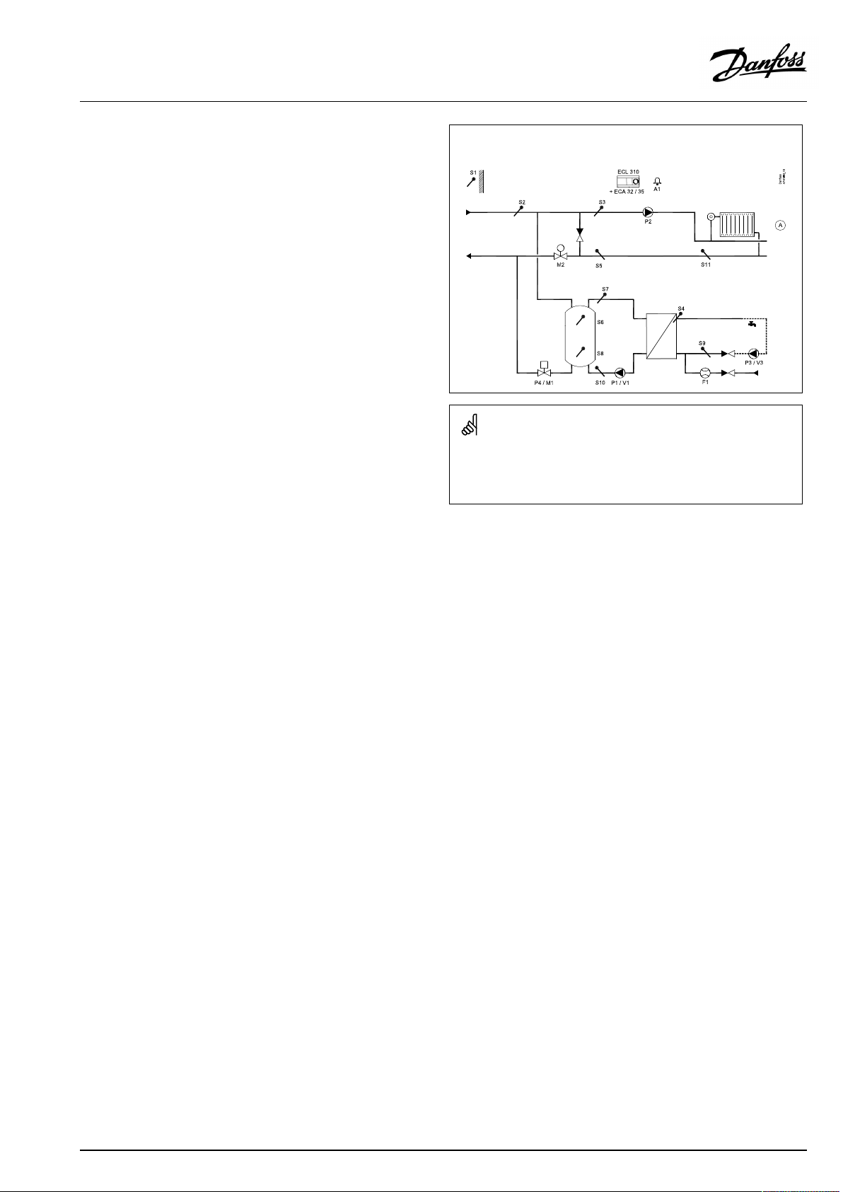
P348.1,ex.b,heating(circuitA)andDHWtemperaturecontrol.Pumpsin
DHWcircuitcanbe0–10Voltcontrolled.
Theshowndiagramisafundamentalandsimplifiedexampleanddoes
notcontainallcomponentsthatarenecessaryinasystem.
AllnamedcomponentsareconnectedtotheECLComfortcontroller.
Listofcomponents:
ECL310
ECA32
ECLComfort310controller
Built-inextensionmodule,0-10Voutputsfor
pumpspeedcontrol
S1
S2
S3
S4
Outdoortemperaturesensor
Supplytemperaturesensor
(mandatory)Flowtemperaturesensor,circuit1
(mandatory)DHWflowtemperaturesensor,circuit
2
S5Returntemperaturesensor,circuit1
S6
S7
S8
S9
S10
(mandatory)Upperbuffertemperaturesensor
Bufferflowtemperaturesensor
Lowerbuffertemperaturesensor
DHWcirculationreturntemperaturesensor
Bufferreturntemperaturesensor
S11Returntemperaturesensor,circuit1A
S15
S16
F1
P1
V1
Supplyreturnpressuresensor
Supplyflowpressuresensor
Flowmeter(signaltype:Pulse)
DHWbufferchargingpump(ON-OFFcontrolled)
SpeedcontrolofDHWbufferchargingpump(0-
10V)
P2
P3
V3
M1
M2
A1
Circulationpump(ON-OFFcontrolled),circuit1
DHWcirculationpump(ON-OFFcontrolled)
SpeedcontrolofDHWcirculationpump(0-10V)
Motorizedcontrolvalve(ON-OFFcontrolled)
Motorizedcontrolvalve(3-pointcontrolled)
Alarm
VI.LV.G3.02
©Danfoss|2018.11|7
Page 8
OperatingGuideECLComfort310,applicationP348
Stopbufferchargingprocess:
1.a
S6connectedand'Stopdiff. 'hasanegativevalue
BuffertemperatureS6temperaturegetshigherthan('Desired
DHWtemperature'+'Demandoffset').
Anexample:60°C+6K=66°C
1.b
S6connectedand'Stopdiff. 'hasa
positivevalue:
BuffertemperatureS6temperaturegetshigherthan('Desired
DHWtemperature'+'Demandoffset'+'Stopdiff.').
Anexample:60°C+6K+4K=70°C
1.c
S6andS8connectedand'Stopdiff.'hasa
negativevalue:
BuffertemperatureS6temperaturegetshigherthan('Desired
DHWtemperature'+'Demandoffset')ANDS8temperature
getshigherthan('DesiredDHWtemperature'+'Demandoffset'
+'Stopdiff. ').
Anexample:S6higherthan(60°C+6K=66°C)ANDS8higher
than(60°C+6K+(-8K)=58°C).
1.d
S6andS8connectedand'Stopdiff.'hasapositivevalue:
BuffertemperatureS6temperaturegetshigherthan('Desired
DHWtemperature'+'Demandoffset')ANDS8temperature
getshigherthan('DesiredDHWtemperature'+'Demandoffset'
+'Stopdiff. ').
Anexample:S6higherthan(60°C+6K=66°C)ANDS8higher
than(60°C+6K+(8K)=74°C).
2.P4isswitchedOFF;M1iscommandedtoclose
P348.1,ex.c,heating(circuitsAandB)andDHWtemperaturecontrol.
PumpsinDHWcircuitcanbe0–10VoltorPWMcontrolled.
Theshowndiagramisafundamentalandsimplifiedexampleanddoes
notcontainallcomponentsthatarenecessaryinasystem.
AllnamedcomponentsareconnectedtotheECLComfortcontroller.
Listofcomponents:
ECL310
ECA32
ECLComfort310controller
Built-inextensionmodule,0-10Voutputsfor
pumpspeedcontrol
ECA35
Built-inextensionmodule,0-10Voutputsand
PWMoutputsforpumpspeedcontrol
S1
S2
S3
S4
Outdoortemperaturesensor
Supplytemperaturesensor
(mandatory)Flowtemperaturesensor,circuit1
(mandatory)DHWflowtemperaturesensor,circuit
2
S5Returntemperaturesensor,circuit1
S6
S7
S8
S9
S10
(mandatory)Upperbuffertemperaturesensor
Bufferflowtemperaturesensor
Lowerbuffertemperaturesensor
DHWcirculationreturntemperaturesensor
Bufferreturntemperaturesensor
S11Returntemperaturesensor,circuit1A
S12Returntemperaturesensor,circuit1B
F1
P1
V1
Flowmeter(signaltype:Pulse)
DHWbufferchargingpump(ON-OFFcontrolled)
SpeedcontrolofDHWbufferchargingpump(0-
10V)
P2
P3
V3
M1
M2
A1
Circulationpump(ON-OFFcontrolled),circuit1
DHWcirculationpump(ON-OFFcontrolled)
SpeedcontrolofDHWcirculationpump(0-10V)
Motorizedcontrolvalve(ON-OFFcontrolled)
Motorizedcontrolvalve(3-pointcontrolled)
Alarm
8|©Danfoss|2018.11
VI.LV.G3.02
Page 9
OperatingGuideECLComfort310,applicationP348
TemperaturecontrolofDHW:
ThedesiredDHWtemperatureatS4determinesthetemperature
control.
Bymeansofaweekschedule(upto3'Comfort'periods/day),the
DHWcircuitcanbein'Comfort'or'Saving'mode(twodifferent
temperaturevaluesforthedesiredDHWtemperatureatS4).
TheDHWflowtemperaturesensorS4andtheDHWcirculation
returntemperaturesensorS9arethemostimportantsensorsand
mustbeconnected.IfS4isnotconnected,thecontrolpumpP1/
V1willstop.IfS9isnotconnected,theDHWcirculationpumpwill
operateat100%speed.
ThecontrolpumpP1/V1isgraduallyincreasedinspeedwhenthe
DHWflowtemperatureislowerthanthedesiredDHWtemperature
andviceversa.
ThesupplytemperatureS7isusedtocompensatetheproportional
bandXpinordertoimprovethetemperaturecontrolatdifferent
supplytemperatures.
TemperaturecontroloftheDHWcirculationpipeatS9ensuresthe
desiredtemperaturebymeansofspeedcontrolofP3/V3.
Aweekschedule(upto3'Comfort'periods/day)controlsthe
DHWcirculationpumptobeONorOFF .IfinOFFmode,theDHW
temperaturecontrolwillbedisabled.
ThecoldwaterflowsignalfromF1canbeusedtooverridethe
controlvalveinordertooptimizetheDHWtemperaturecontrol.
Thispro-activefunctionalitycompensatesforthedelaybeforethe
flowtemperaturesensorS4measuresachangeintemperature.
Ananti-bacteriafunctionfortheDHWcircuitisavailablefor
activationonselecteddaysoftheweek.Theanti-bacteriafunction
canbesettoincludetheDHWcirculation.
P348.1,ex.d,heating(circuitA)andDHWtemperaturecontrol.Pumpsin
DHWcircuitcanbe0–10VoltorPWMcontrolled.
Theshowndiagramisafundamentalandsimplifiedexampleanddoes
notcontainallcomponentsthatarenecessaryinasystem.
AllnamedcomponentsareconnectedtotheECLComfortcontroller.
Listofcomponents:
ECL310
ECA32
ECLComfort310controller
Built-inextensionmodule,0-10Voutputsfor
pumpspeedcontrol
ECA35
Built-inextensionmodule,0-10Voutputsand
PWMoutputsforpumpspeedcontrol
S1
S2
S3
S4
Outdoortemperaturesensor
Supplytemperaturesensor
(mandatory)Flowtemperaturesensor,circuit1
(mandatory)DHWflowtemperaturesensor,circuit
2
S5Returntemperaturesensor,circuit1
S6
S7
S8
S9
S10
(mandatory)Upperbuffertemperaturesensor
Bufferflowtemperaturesensor
Lowerbuffertemperaturesensor
DHWcirculationreturntemperaturesensor
Bufferreturntemperaturesensor
S11Returntemperaturesensor,circuit1A
F1
P1
V1
Flowmeter(signaltype:Pulse)
DHWbufferchargingpump(ON-OFFcontrolled)
SpeedcontrolofDHWbufferchargingpump(0-
10V)
P2
P3
V3
M1
M2
A1
Circulationpump(ON-OFFcontrolled),circuit1
DHWcirculationpump(ON-OFFcontrolled)
SpeedcontrolofDHWcirculationpump(0-10V)
Motorizedcontrolvalve(ON-OFFcontrolled)
Motorizedcontrolvalve(3-pointcontrolled)
Alarm
VI.LV.G3.02
©Danfoss|2018.11|9
Page 10

OperatingGuideECLComfort310,applicationP348
P348,ingeneral
UptotwoRemoteControlUnits,ECA30/31,canbeconnectedto
oneECLcontrollerinordertocontroltheECLcontrollerremotely.
AdditionalECLComfortcontrollerscanbeconnectedviatheECL
485businordertoutilizecommonoutdoortemperaturesignal,
timeanddatesignals.
TheECLcontrollersintheECL485systemcanworkinmasterslavesystem.
Whenconnectinganoverrideswitchorarelaycontacttoan
unusedinputtheECL310'sschedulecanbeoverriddento:
•Comfortmode
•Savingmode
•Frostprotectionmodeor
•Constanttemperaturemode(keepingasetdesiredflow
temperature).
ModbuscommunicationtoaSCADAsystemcanbeestablished.
Heat-meters:
Upto5heat-meterscanbeconnectedtotheM-busterminals.
M-busdatacanbetransferredtotheSCADAsystemviaModbus
andTCP/IPtotheECLPortal.
AlarmA1(=relay6)canbeactivatedif:
•Theactualflowtemperaturediffersfromthedesiredflow
temperature.
•Ifatemperaturesensororitsconnectiondisconnects/short
circuits.(See:Commoncontrollersettings>System>Raw
inputoverview).
Ameasuredtemperaturecanbeoffsetadjusted,ifneeded.
10|©Danfoss|2018.11
VI.LV.G3.02
Page 11

OperatingGuideECLComfort310,applicationP348
PWM(PulseWidthModulation)
A200HzfrequencyisappliedtothePWMcontrolledpump.The
dutycycle(thepercentageoftheperiodtime)determinesthe
pumpspeed.
Pumpspeed,PWMor0–10Voltcontrolled
Sometypesofspeedcontrolledpumpsarelimitedtoaminimum
speed,forexample30%(PWMor3.0Volt).Eveniftheapplied
control%getslowerthan30%,thepumpspeedremainsonthe
minimumlevel*.
Furthermore,whentheappliedcontrol%getsbelow,forexample,
10%,thepumpswitchesOFF.Inordertogetthepumpswitched
ONagain,theappliedcontrol%mustexceed20%.
Thisbehaviorcan,atlowloadoratoobigpump,causeunstable
temperatureregulation.Toavoidthis,theP348hasafunction
wheretheappliedcontrolsignalisconvertedintoapulsedsignal.
Thepumpisshortlystoppedandthenstartedagain.Theresultisa
pumpspeedcontrolalsobelowtheminimumspeedlevel.
Theparameters"PWMperiod"(ID12565)and"Adapttime"(ID
12065)areusedforthisfunctionality.
*)Seethepumpmanufacturer'sdatasheet
Commissioning
WhentheP348applicationhasbeenuploadedtheECLComfort
310controllerstartsinManualmode.Thiscanbeusedtoverify
correctconnectionsoftemperature,pressureandflowsensors.
Alsoverifyingthecontrolledcomponentsforcorrectfunctionality
canbedone.
Dependingonsystemtype,itmightbenecessarytochangesome
factorysettingsindividuallyinordertooptimizethefunctionality.
Theapplicationkeymustbeinsertedinordertochangesettings.
Important:
•Setthecorrectrunningtime"Mrun"oftheMotorizedControl
ValveM2.(Circuit1>MENU>Settings>Controlparameters
>Mrun).
•SetaminimumspeedofP1/V1andensurethatthepumpruns
constantly.(Circuit2>MENU>Settings>Controlpar.1>Vout
min.).Seepumpmanufacturer'smanual.
•Verifyifthespeedcontrolledpumpsshouldbereversed
controlled.(Circuit2/3>MENU>Settings>Controlpar.>
Reverseout).Seepumpmanufacturer'smanual.
Thecontrollerispre-programmedwithfactorysettingsthatareshown
inthe‘ParameterIDoverview’appendix.
VI.LV.G3.02
©Danfoss|2018.11|11
Page 12
OperatingGuideECLComfort310,applicationP348
2.2Identifyingthesystemtype
Sketchyourapplication
TheECLComfortcontrollerseriesisdesignedforawiderange
ofheating,domestichot-water(DHW)andcoolingsystemswith
differentconfigurationsandcapacities.Ifyoursystemdiffers
fromthediagramsshownhere,youmaywanttomakeasketch
ofthesystemabouttobeinstalled.Thismakesiteasiertouse
theOperatingGuide,whichwillguideyoustep-by-stepfrom
installationtofinaladjustmentsbeforetheend-usertakesover.
TheECLComfortcontrollerisauniversalcontrollerthatcanbe
usedforvarioussystems.Basedontheshownstandardsystems,
itispossibletoconfigureadditionalsystems.Inthischapteryou
findthemostfrequentlyusedsystems.Ifyoursystemisnotquite
asshownbelow,findthediagramwhichhasthebestresemblance
withyoursystemandmakeyourowncombinations.
SeetheInstallationGuide(deliveredwiththeapplicationkey)for
applicationtypes/sub-types.
12|©Danfoss|2018.11
VI.LV.G3.02
Page 13
OperatingGuideECLComfort310,applicationP348
2.3Mounting
2.3.1MountingtheECLComfortcontroller
SeetheInstallationGuidewhichisdeliveredtogetherwiththe
ECLComfortcontroller.
Foreasyaccess,youshouldmounttheECLComfortcontrollernear
thesystem.
ECLComfort210/296/310canbemounted
•onawall
•onaDINrail(35mm)
ECLComfort296canbemounted
•inapanelcut-out
ECLComfort210canbemountedinanECLComfort310basepart
(forfutureupgrade).
Screws,PGcableglandsandrawlplugsarenotsupplied.
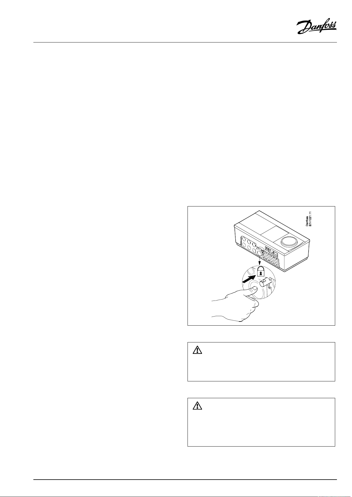
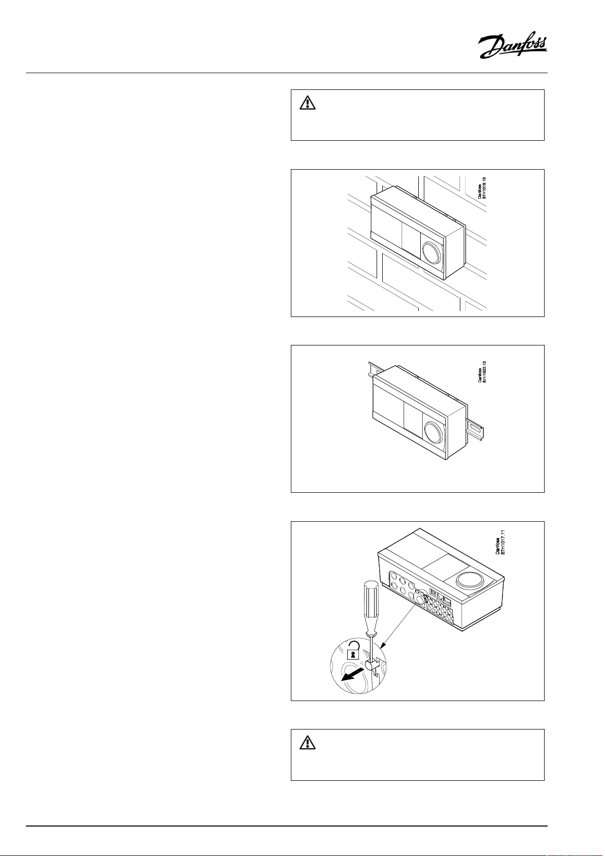
LockingtheECLComfort210/310controller
InordertofastentheECLComfortcontrollertoitsbasepart,secure
thecontrollerwiththelockingpin.
Topreventinjuriestopersonsorthecontroller,thecontrollerhasto
besecurelylockedintothebase.Forthispurpose,pressthelocking
pinintothebaseuntilaclickisheardandthecontrollernolonger
canberemovedfromthebase.
Ifthecontrollerisnotsecurelylockedintothebasepart,thereisarisk
thatthecontrollerduringoperationcanunlockfromthebaseandthe
basewithterminals(andalsothe230Va.c.connections)areexposed.
Topreventinjuriestopersons,alwaysmakesurethatthecontroller
issecurelylockedintoitsbase.Ifthisisnotthecase,thecontroller
shouldnotbeoperated!
VI.LV.G3.02
©Danfoss|2018.11|13
Page 14
OperatingGuideECLComfort310,applicationP348
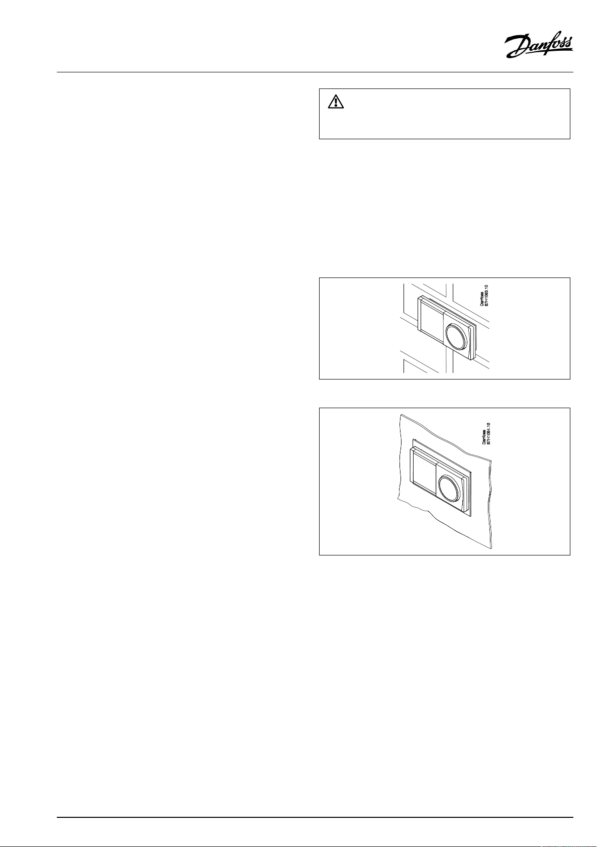
Mountingonawall
Mountthebasepartonawallwithasmoothsurface.Establishthe
electricalconnectionsandpositionthecontrollerinthebasepart.
Securethecontrollerwiththelockingpin.
MountingonaDINrail(35mm)
MountthebasepartonaDINrail.Establishtheelectrical
connectionsandpositionthecontrollerinthebasepart.Secure
thecontrollerwiththelockingpin.
Theeasywaytolockthecontrollertoitsbaseorunlockitistousea
screwdriveraslever.
DismountingtheECLComfortcontroller
Inordertoremovethecontrollerfromthebasepart,pulloutthe
lockingpinbymeansofascrewdriver.Thecontrollercannowbe
removedfromthebasepart.
Theeasywaytolockthecontrollertoitsbaseorunlockitistousea
screwdriveraslever.
14|©Danfoss|2018.11
VI.LV.G3.02
Page 15
OperatingGuideECLComfort310,applicationP348
2.3.2MountingtheRemoteControlUnitsECA30/31
Selectoneofthefollowingmethods:
•Mountingonawall,ECA30/31
•Mountinginapanel,ECA30
Screwsandrawlplugsarenotsupplied.
Mountingonawall
MountthebasepartoftheECA30/31onawallwithasmooth
surface.Establishtheelectricalconnections.PlacetheECA30/
31inthebasepart.
BeforeremovingtheECLComfortcontrollerfromthebasepart,ensure
thatthesupplyvoltageisdisconnected.
Mountinginapanel
MounttheECA30inapanelusingtheECA30framekit(ordercode
no.087H3236).Establishtheelectricalconnections.Securethe
framewiththeclamp.PlacetheECA30inthebasepart.TheECA
30canbeconnectedtoanexternalroomtemperaturesensor.
TheECA31mustnotbemountedinapanelifthehumidity
functionistobeused.
VI.LV.G3.02
©Danfoss|2018.11|15
Page 16
OperatingGuideECLComfort310,applicationP348
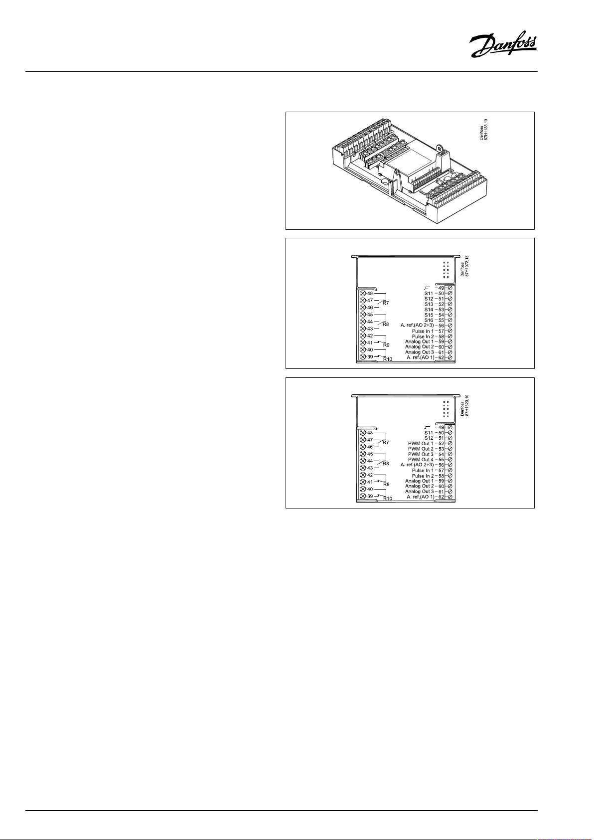
2.3.3MountingtheinternalI/OmoduleECA32orECA35
TheECA32module(ordercodeno.087H3202)orECA35module
(ordercodeno.087H3205)canbeinsertedintotheECLComfort
310/310Bbasepartforadditionalinputandoutputsignalsin
relevantapplications.
ECA32
ECA35
16|©Danfoss|2018.11
VI.LV.G3.02
Page 17
OperatingGuideECLComfort310,applicationP348
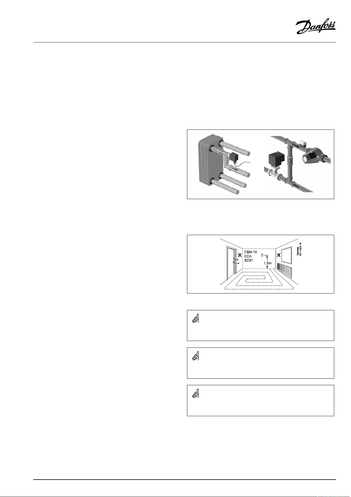
2.4Placingthetemperaturesensors
2.4.1Placingthetemperaturesensors
Itisimportantthatthesensorsaremountedinthecorrectposition
inyoursystem.
Thetemperaturesensormentionedbelowaresensorsusedforthe
ECLComfort210/296/310serieswhichnotallwillbeneeded
foryourapplication!
Outdoortemperaturesensor(ESMT)
Theoutdoorsensorshouldbemountedonthatsideofthebuilding
whereitislesslikelytobeexposedtodirectsunshine.Itshouldnot
beplacedclosetodoors,windowsorairoutlets.
Flowtemperaturesensor(ESMU,ESM-11orESMC)
Placethesensormax.15cmfromthemixingpoint.Insystems
withheatexchanger,DanfossrecommendsthattheESMU-typeto
beinsertedintotheexchangerflowoutlet.
Makesurethatthesurfaceofthepipeiscleanandevenwhere
thesensorismounted.
Returntemperaturesensor(ESMU,ESM-11orESMC)
Thereturntemperaturesensorshouldalwaysbeplacedsothatit
measuresarepresentativereturntemperature.
Roomtemperaturesensor
(ESM-10,ECA30/31RemoteControlUnit)
Placetheroomsensorintheroomwherethetemperatureistobe
controlled.Donotplaceitonoutsidewallsorclosetoradiators,
windowsordoors.
Boilertemperaturesensor(ESMU,ESM-11orESMC)
Placethesensoraccordingtotheboilermanufacturer’s
specification.
Airducttemperaturesensor(ESMB-12orESMUtypes)
Placethesensorsothatitmeasuresarepresentativetemperature.
DHWtemperaturesensor(ESMUorESMB-12)
PlacetheDHWtemperaturesensoraccordingtothemanufacturer’s
specification.
Slabtemperaturesensor(ESMB-12)
Placethesensorinaprotectiontubeintheslab.
ESM-11:Donotmovethesensorafterithasbeenfastenedinorderto
avoiddamagetothesensorelement.
ESM-11,ESMCandESMB-12:Useheatconductingpasteforquick
measurementofthetemperature.
ESMUandESMB-12:Usingasensorpockettoprotectthesensorwill,
however,resultinaslowertemperaturemeasurement.
VI.LV.G3.02
©Danfoss|2018.11|17
Page 18
OperatingGuideECLComfort310,applicationP348
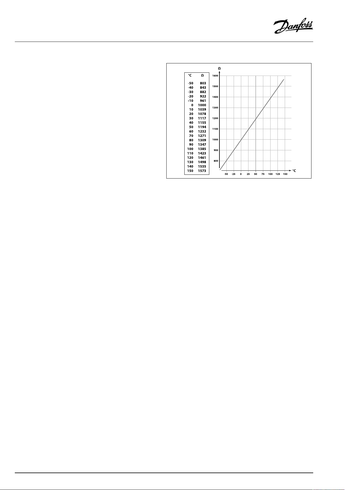
Pt1000temperaturesensor(IEC751B,1000Ω/0°C)
Relationshipbetweentemperatureandohmicvalue:
18|©Danfoss|2018.11
VI.LV.G3.02
Page 19
OperatingGuideECLComfort310,applicationP348
2.5Electricalconnections
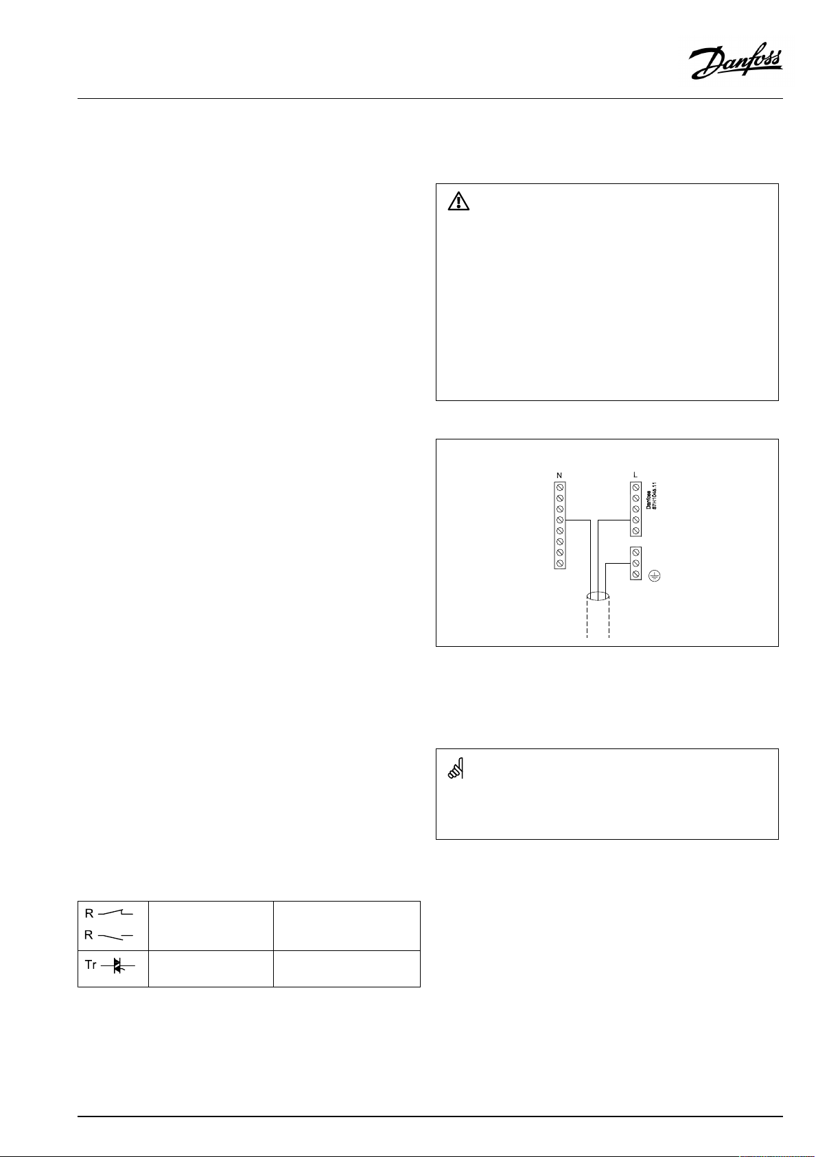
2.5.1Electricalconnections230Va.c.
SafetyNote
Necessaryassembly,start-up,andmaintenanceworkmustbe
performedbyqualifiedandauthorizedpersonnelonly.
Locallegislationsmustberespected.Thiscomprisesalsocablesize
andisolation(reinforcedtype).
AfusefortheECLComfortinstallationismax.10Atypically.
TheambienttemperaturerangefortheECLComfortinoperationis
0-55°C.Exceedingthistemperaturerangecanresultinmalfunctions.
Installationmustbeavoidedifthereisariskforcondensation(dew).
Thecommongroundterminalisusedforconnectionofrelevant
components(pumps,motorizedcontrolvalves).
SeealsotheInstallationGuide(deliveredwiththeapplicationkey)
forapplicationspecificconnections.
ECL210/310
Wirecrosssection:0.5-1.5mm²
Incorrectconnectioncandamagetheelectronicoutputs.
Max.2x1.5mm²wirescanbeinsertedintoeachscrewterminal.
Maximumloadratings:
VI.LV.G3.02
Relayterminals
Triac(=electronic
relay)terminals
4(2)A/230Va.c.
(4Aforohmicload,2Afor
inductiveload)
0,2A/230Va.c.
©Danfoss|2018.11|19
Page 20
OperatingGuideECLComfort310,applicationP348
Electricalconnections,ECA32/ECA35
Connections,ingeneral.
SeealsotheInstallationGuide(deliveredwiththeapplicationkey)forapplicationspecificconnections.
Maximumloadratings:
Terminals
ECA32ECA35
PWMOut1(52)
PWMOut2(53)
PWMOut3(54)
PWMOut4(55)
AnalogOut1(59)AnalogOut1(59)47kΩ*
AnalogOut2(60)AnalogOut2(60)47kΩ*
AnalogOut3(61)AnalogOut3(61)47kΩ*
*Thevalueisaminimum.
5kΩ*
5kΩ*
5kΩ*
5kΩ*
20|©Danfoss|2018.11
VI.LV.G3.02
Page 21
OperatingGuideECLComfort310,applicationP348
2.5.2Electricalconnections,Pt1000temperaturesensors
SeetheInstallationGuide(deliveredwiththeapplicationkey)for
sensorandinputconnections.
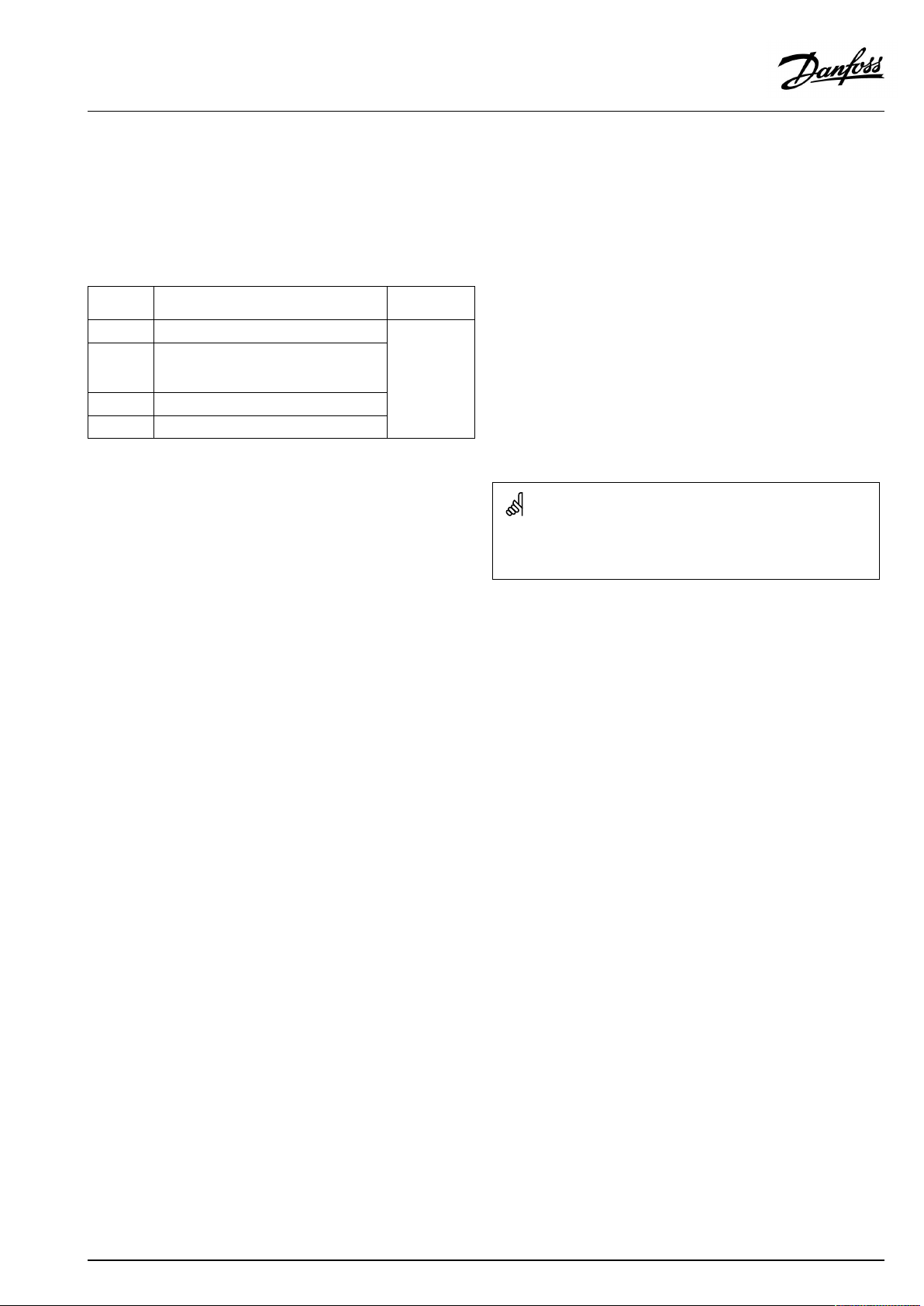
P348
Sensor
S1
S2
S3
S4
S5Returntemperature
S6
S7
S8
S9
S10
Description
Outdoortemperaure
sensor
Supplytemperature
sensor
Flowtemperature
sensor(heating)*
Flowtemperature
sensor(DHW)*
sensor(heating)
Upperbuffer-tank
temperaturesensor*
Buffer-tankflow
temperaturesensor
Lowerbuffer-tank
temperaturesensor
DHWcirculation
temperaturesensor
Buffer-tankreturn
temperaturesensor
Recommendedtype
ESMT
ESM-11/
ESMB/
ESMC/
ESMU
ESM-11/
ESMB/
ESMC/
ESMU
ESMB/
ESMU
ESM-11/
ESMB/
ESMC/
ESMU
ESMB/
ESMU
ESM-11/
ESMB/
ESMC/
ESMU
ESMB/
ESMU
ESM-11/
ESMB/
ESMC/
ESMU
ESM-11/
ESMB/
ESMC/
ESMU
Temperaturesensorsmustbeconnectedinordertohavethe
desiredfunctionality.
*
Ifthesensorisnotconnectedorthesensorcableis
short-circuited,themotorizedcontrolvalveorcontrolpump
closes/stops(safetyfunction).
VI.LV.G3.02
©Danfoss|2018.11|21
Page 22
OperatingGuideECLComfort310,applicationP348
ECA32
Sensor
S11Returntemperature
Description
sensor,heatingcircuitA
Recommendedtype
ESM-11/
ESMB/
ESMC/
ESMU
S12Returntemperature
sensor,heatingcircuitB
ESM-11/
ESMB/
ESMC/
ESMU
S13
S14
S15
Notused
Notused
Supplyreturnpressure
sensor
S16
Supplyreturnpressure
sensor
Temperaturesensorsmustbeconnectedinordertohavethe
desiredfunctionality.
ECA35
Sensor
S11Returntemperature
Description
sensor,heatingcircuitA
Recommendedtype
ESM-11/
ESMB/
ESMC/
ESMU
S12Returntemperature
sensor,heatingcircuitB
ESM-11/
ESMB/
ESMC/
ESMU
Temperaturesensorsmustbeconnectedinordertohavethe
desiredfunctionality.
Wirecrosssectionforsensorconnections:Min.0.4mm².
Totalcablelength:Max.200m(allsensorsincl.internalECL485
communicationbus).
Cablelengthsofmorethan200mmaycausenoisesensibility(EMC).
22|©Danfoss|2018.11
VI.LV.G3.02
Page 23
OperatingGuideECLComfort310,applicationP348
2.5.3Electricalconnections,ECA30/31
Terminal
ECL
Terminal
ECA30/31
30
31
4
1
322
333
4
5
*
Afteranexternalroomtemperaturesensorhasbeenconnected,
Description
Twistedpair
Twistedpair
Ext.roomtemperature
sensor*
Type
(recomm.)
Cable2x
twistedpair
ESM-10
ECA30/31mustberepowered.
ThecommunicationtotheECA30/31mustbesetupintheECL
Comfortcontrollerin'ECAaddr.'
TheECA30/31mustbesetupaccordingly.
AfterapplicationsetuptheECA30/31isreadyafter2–5min.A
progressbarintheECA30/31isdisplayed.
Iftheactualapplicationcontainstwoheatingcircuits,itispossible
toconnectanECA30/31toeachcircuit.Theelectricalconnections
aredoneinparallel.
Max.2ECA30/31canbeconnectedtoanECLComfort310controller
ortoECLComfort210/296/310controllersinamaster-slavesystem.
SetupproceduresforECA30/31:Seesection‘Miscellaneous’ .
ECAinformationmessage:
‘Applicationreq.newerECA’:
Thesoftware(firmware)ofyourECAdoesnotcomplywiththe
software(firmware)ofyourECLComfortcontroller.Pleasecontact
yourDanfosssalesoffice.
Someapplicationsdonotcontainfunctionsrelatedtoactualroom
temperature.TheconnectedECA30/31willonlyfunctionasremote
control.
VI.LV.G3.02
©Danfoss|2018.11|23
Page 24
OperatingGuideECLComfort310,applicationP348
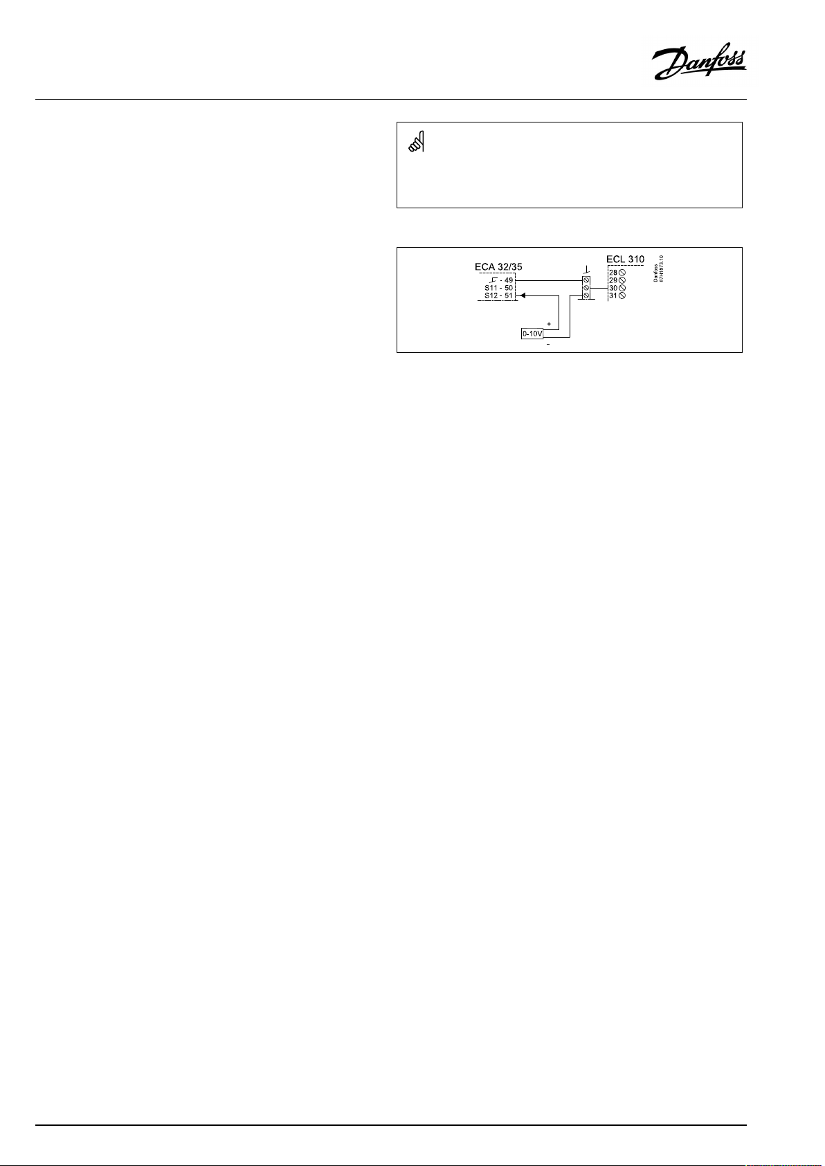
ECA32/35
S12
Connectionofvoltagesignal(0–10V)forexternalcontrolofdesired
DHWtemperature.
Theappliedvoltagemust,asaminimum,be1Volt.
Totalcablelength:Max.200m(allsensorsincl.internalECL485
communicationbus).
Cablelengthsofmorethan200mmaycausenoisesensibility(EMC).
24|©Danfoss|2018.11
VI.LV.G3.02
Page 25
OperatingGuideECLComfort310,applicationP348
2.5.4Electricalconnections,master/slavesystems
Thecontrollercanbeusedasmasterorslaveinmaster/slave
systemsviatheinternalECL485communicationbus(2xtwisted
paircable).
TheECL485communicationbusisnotcompatiblewiththeECL
businECLComfort110,200,300and301!
Terminal
Description
30
Commonterminal
+12V*,ECL485communicationbus
31
*OnlyforECA30/31andmaster/
slavecommunication
32
B,ECL485communicationbus
33
A,ECL485communicationbus
2.5.5Electricalconnections,communication
Electricalconnections,Modbus
ECLComfort210:Non-galvanicisolatedModbusconnections
ECLComfort296:GalvanicisolatedModbusconnections
ECLComfort310:GalvanicisolatedModbusconnections
Type
(recomm.)
Cable2x
twistedpair
Totalcablelength:Max.200m(allsensorsincl.internalECL485
communicationbus).
Cablelengthsofmorethan200mmaycausenoisesensibility(EMC).
2.5.6Electricalconnections,communication
Electricalconnections,M-bus
ECLComfort210:Notimplemented
ECLComfort296:Onboard
ECLComfort310:Onboard
VI.LV.G3.02
©Danfoss|2018.11|25
Page 26
OperatingGuideECLComfort310,applicationP348
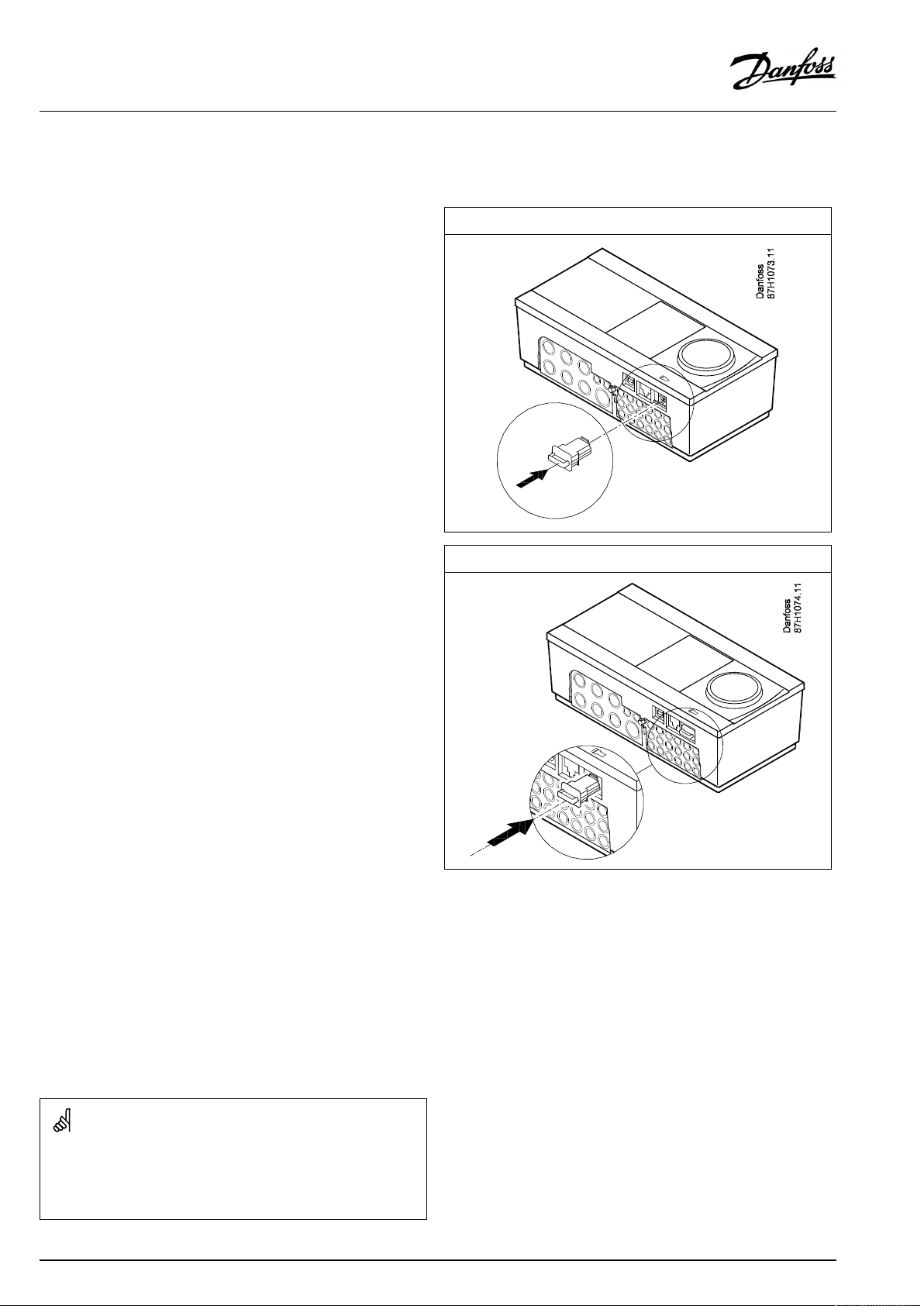
2.6InsertingtheECLApplicationKey
2.6.1InsertingtheECLApplicationKey
TheECLApplicationKeycontains
•theapplicationanditssubtypes,
•currentlyavailablelanguages,
•factorysettings:e.g.schedules,desiredtemperatures,
limitationvaluesetc.Itisalwayspossibletorecoverthefactory
settings,
•memoryforusersettings:specialuser/systemsettings.
Afterhavingpowered-upthecontroller,differentsituationsmight
beexisting:
1.Thecontrollerisnewfromthefactory,theECLApplicationKey
isnotinserted.
2.Thecontrolleralreadyrunsanapplication.TheECLApplication
Keyisinserted,buttheapplicationneedstobechanged.
3.Acopyofthecontrollerssettingsisneededforconfiguring
anothercontroller.
ECLComfort210/310
ECLComfort210/310
Usersettingsare,amongothers,desiredroomtemperature,desired
DHWtemperature,schedules,heatcurve,limitationvaluesetc.
Systemsettingsare,amongothers,communicationset-up,display
brightnessetc.
26|©Danfoss|2018.11
VI.LV.G3.02
Page 27
OperatingGuideECLComfort310,applicationP348
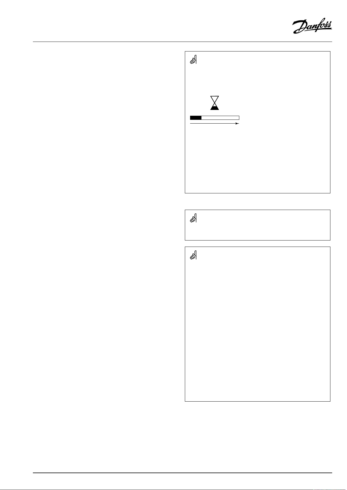
Automaticupdateofcontrollersoftware(firmware):
Thesoftwareofthecontrollerisupdatedautomaticallywhenthekey
isinserted(asofcontrollerversion1.11(ECL210/310)andversion
1.58(ECL296)).Thefollowinganimationwillbeshownwhenthe
softwareisbeingupdated:
Progressbar
Duringupdate:
•DonotremovetheKEY
Ifthekeyisremovedbeforethehour-glassisshown,youhave
tostartafresh.
•Donotdisconnectthepower
Ifthepowerisinterruptedwhenthehour-glassisshown,the
controllerwillnotwork.
•Manualupdateofcontrollersoftware(firmware):
Seethesection"Automatic/manualupdateoffirmware"
The“Keyoverview”doesnotinform—throughECA30/31—about
thesubtypesoftheapplicationkey.
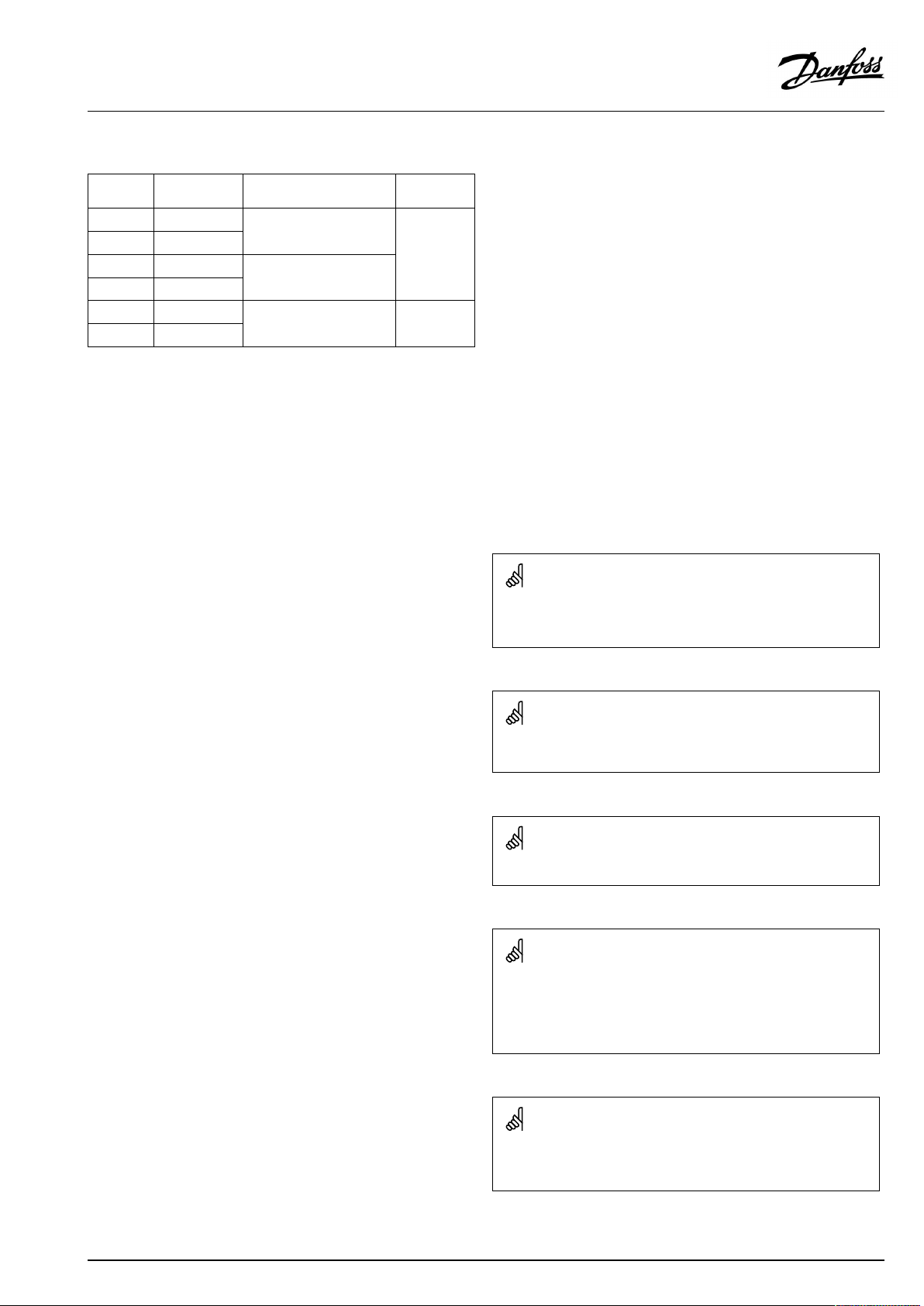
Keyinserted/notinserted,description:
ECLComfort210/310,controllerversionslowerthan1.36:
-
Takeouttheapplicationkey;for20minutes
settingscanbechanged.
-
Powerupthecontrollerwithoutthe
applicationkeyinserted;for20minutes
settingscanbechanged.
ECLComfort210/310,controllerversions1.36andup:
-
Takeouttheapplicationkey;for20minutes
settingscanbechanged.
-
Powerupthecontrollerwithoutthe
applicationkeyinserted;settingscannotbe
changed.
ECLComfort296,controllerversions1.58andup:
-
Takeouttheapplicationkey;for20minutes
settingscanbechanged.
-
Powerupthecontrollerwithoutthe
applicationkeyinserted;settingscannotbe
changed.
VI.LV.G3.02
©Danfoss|2018.11|27
Page 28

OperatingGuideECLComfort310,applicationP348
ApplicationKey:Situation1
Thecontrollerisnewfromthefactory,theECLApplicationKey
isnotinserted.
AnanimationfortheECLApplicationKeyinsertionisdisplayed.
InserttheApplicationKey.
ApplicationKeynameandVersionisindicated(example:A266
Ver.1.03).
IftheECLApplicationKeyisnotsuitableforthecontroller,a"cross"
isdisplayedovertheECLApplicationKey-symbol.
Action:Purpose:
Selectlanguage
Confirm
Selectapplication(subtype)
Somekeyshaveonlyoneapplication.
Confirmwith‘Yes’
Set'Time&Date'
Turnandpushthedialtoselectand
change'Hours' ,'Minutes','Date',
'Month'and'Year' .
Choose''Next'
Confirmwith‘Yes’
Goto‘Aut.daylight’
Choosewhether‘ Aut.daylight´*
shouldbeactiveornot
*‘Aut.daylight’istheautomaticchangeoverbetweensummer
andwintertime.
DependingonthecontentsoftheECLApplicationKey,procedure
AorBistakingplace:
A
TheECLApplicationkeycontainsfactorysettings:
Thecontrollerreads/transfersdatafromtheECLApplicationKey
toECLcontroller.
Examples:
YESorNO
Theapplicationisinstalled,andthecontrollerresetsandstartsup.
B
TheECLApplicationkeycontainschangedsystemsettings:
Pushthedialrepeatedly.
’NO’:
’YES*:
Ifthekeycontainsusersettings:
Pushthedialrepeatedly.
‘NO:
‘YES*:
*If‘YES’cannotbechosen,theECLApplicationKeydoesnot
containanyspecialsettings.
Choose‘Startcopying’andconfirmwith'Yes'.
28|©Danfoss|2018.11
OnlyfactorysettingsfromtheECLApplicationKeywill
becopiedtothecontroller.
Specialsystemsettings(differingfromthefactory
settings)willbecopiedtothecontroller.
OnlyfactorysettingsfromtheECLApplicationKeywill
becopiedtothecontroller.
Specialusersettings(differingfromthefactorysettings)
willbecopiedtothecontroller.
VI.LV.G3.02
Page 29
OperatingGuideECLComfort310,applicationP348
(Example):
The"i"intheupperrightcornerindicatesthat-besidesthefactory
settings-thesubtypealsocontainsspecialuser/systemssettings.
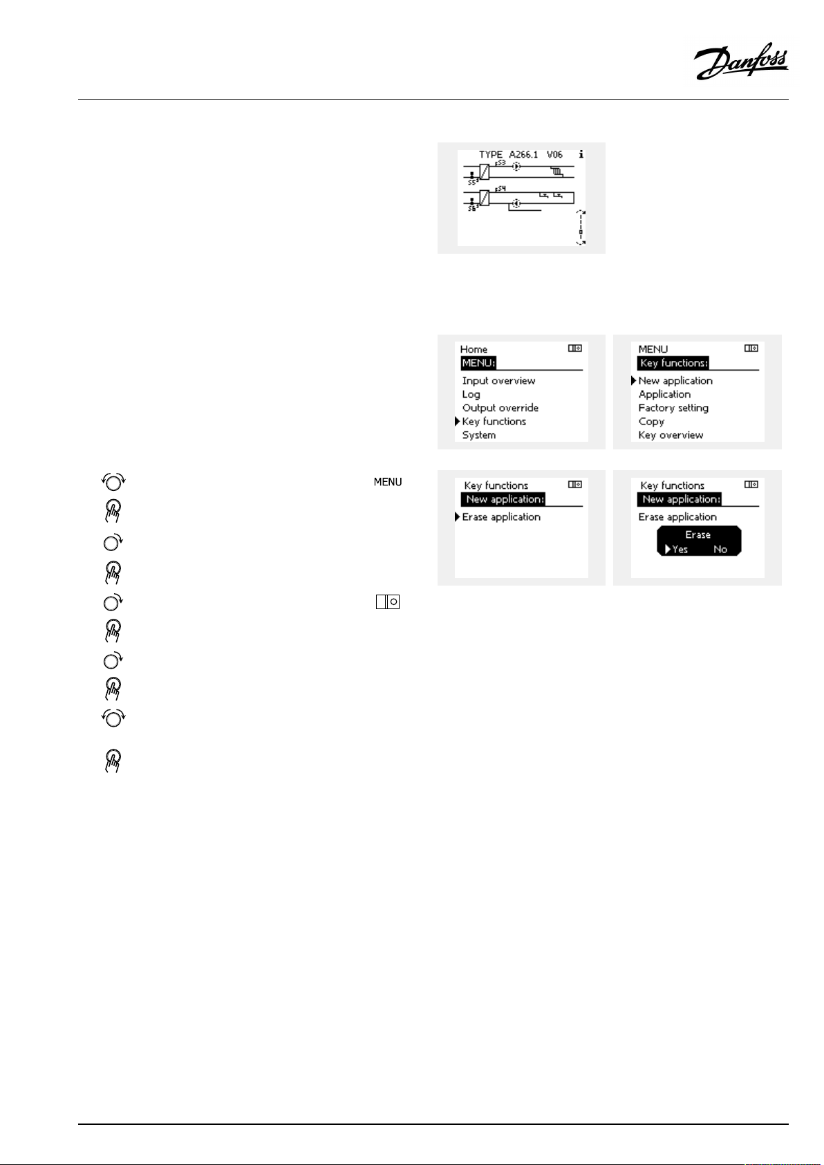
ApplicationKey:Situation2
Thecontrolleralreadyrunsanapplication.TheECLApplication
Keyisinserted,buttheapplicationneedstobechanged.
TochangetoanotherapplicationontheECLApplicationKey,the
currentapplicationinthecontrollermustbeerased(deleted).
BeawarethattheApplicationKeymustbeinserted.
Action:Purpose:
Choose‘MENU’inanycircuit
Confirm
Choosethecircuitselectoratthetop
rightcornerinthedisplay
Confirm
Choose‘Commoncontrollersettings’
Confirm
Choose‘Keyfunctions’
Confirm
Choose‘Eraseapplication’
Confirmwith‘Yes’
Thecontrollerresetsandisreadytobeconfigured.
Followtheproceduredescribedinsituation1.
Examples:
VI.LV.G3.02
©Danfoss|2018.11|29
Page 30
OperatingGuideECLComfort310,applicationP348
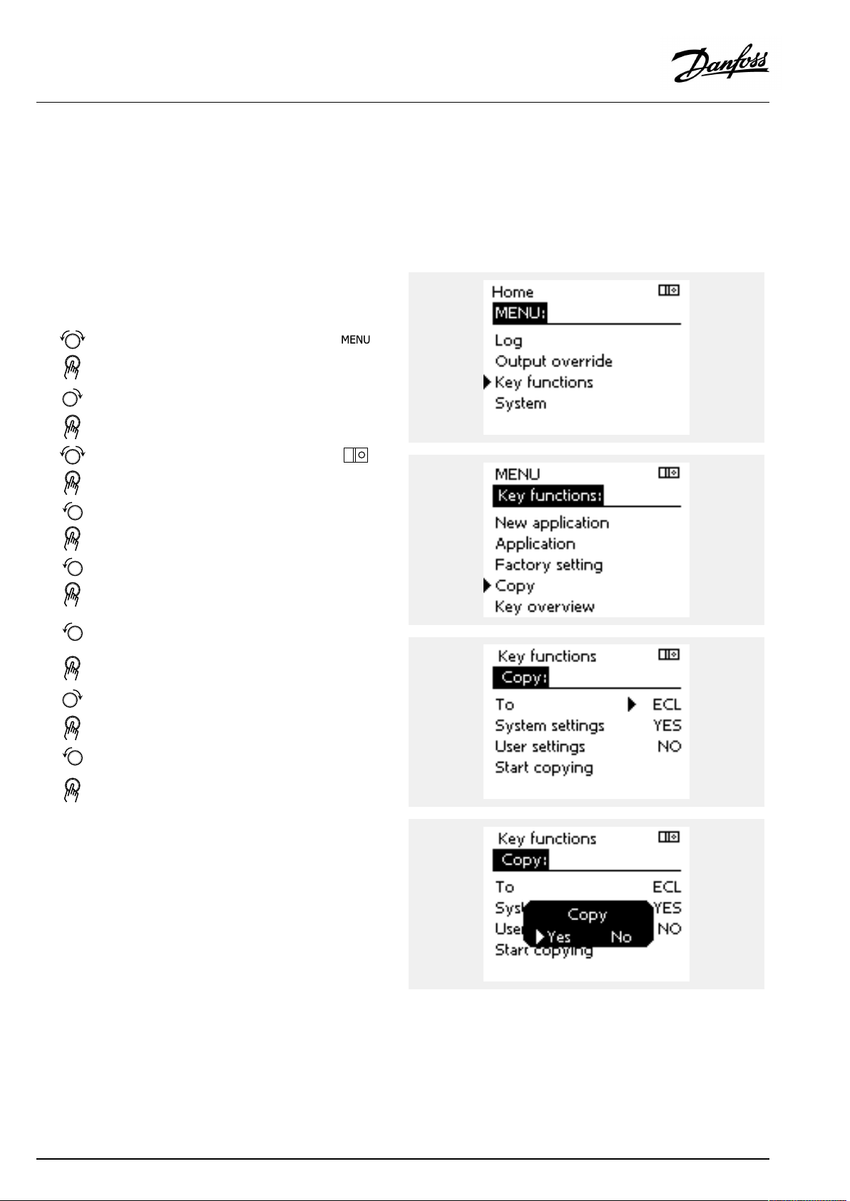
ApplicationKey:Situation3
Acopyofthecontrollerssettingsisneededforconfiguring
anothercontroller.
Thisfunctionisused
•forsaving(backup)ofspecialuserandsystemsettings
•whenanotherECLComfortcontrollerofthesametype(210,
296or310)mustbeconfiguredwiththesameapplicationbut
user/systemsettingsdifferfromthefactorysettings.
HowtocopytoanotherECLComfortcontroller:
Action:Purpose:
Choose‘MENU’
Confirm
Choosethecircuitselectoratthetop
rightcornerinthedisplay
Confirm
Choose'Commoncontrollersettings'
Confirm
Goto‘Keyfunctions’
Confirm
Choose‘Copy’
Confirm
Choose‘To’ .
‘ECL’or‘KEY’willbeindicated.Choose
’ECL’orKEY’
Pushthedialrepeatedlytochoose
copydirection
Choose‘Systemsettings’or‘User
settings’
Pushthedialrepeatedlytochoose
‘Yes’or‘No’in‘Copy’ .Pushtoconfirm.
Choose‘Startcopying’
TheApplicationKeyorthecontroller
isupdatedwithspecialsystemoruser
settings.
Examples:
*
’ECL’or‘KEY’ .
**
‘NO’or‘YES’
*
‘ECL’:
‘KEY’:
**
‘NO’:
‘YES’:
30|©Danfoss|2018.11
DatawillbecopiedfromtheApplicationKeytothe
ECLController.
DatawillbecopiedfromtheECLControllertothe
ApplicationKey.
ThesettingsfromtheECLcontrollerwillnotbecopied
totheApplicationKeyortotheECLComfortcontroller.
Specialsettings(differingfromthefactorysettings)will
becopiedtotheApplicationKeyortotheECLComfort
controller.IfYEScannotbechosen,therearenospecial
settingstobecopied.
VI.LV.G3.02
Page 31

OperatingGuideECLComfort310,applicationP348
2.6.2ECLApplicationKey,copyingdata
Generalprinciples
Whenthecontrollerisconnectedandoperating,youcancheck
andadjustallorsomeofthebasicsettings.Thenewsettingscan
bestoredontheKey.
HowtoupdatetheECLApplicationKeyaftersettingshave
beenchanged?
AllnewsettingscanbestoredontheECLApplicationKey.
Factorysettingscanalwaysberestored.
Howtostorefactorysettinginthecontrollerfromthe
ApplicationKey?
PleasereadtheparagraphconcerningApplicationKey,Situation
1:Thecontrollerisnewfromthefactory,theECLApplicationKey
isnotinserted.
HowtostorepersonalsettingsfromthecontrollertotheKey?
PleasereadtheparagraphconcerningApplicationKey,Situation3:
Acopyofthecontrollerssettingsisneededforconfiguringanother
controller
Asamainrule,theECLApplicationKeyshouldalwaysremainin
thecontroller.IftheKeyisremoved,itisnotpossibletochange
settings.
Makeanoteofnewsettingsinthe'Settingsoverview'table.
DonotremovetheECLApplicationKeywhilecopying.Thedataon
theECLApplicationKeycanbedamaged!
ItispossibletocopysettingsfromoneECLComfortcontrollerto
anothercontrollerprovidedthatthetwocontrollersarefromthesame
series(210or310).
Furthermore,whentheECLComfortcontrollerhasbeenuploaded
withanapplicationkey,minimumversion2.44,itispossibletoupload
personalsettingsfromapplicationkeys,minimumversion2.14.
The“Keyoverview”doesnotinform—throughECA30/31—about
thesubtypesoftheapplicationkey.
Keyinserted/notinserted,description:
ECLComfort210/310,controllerversionslowerthan1.36:
-
Takeouttheapplicationkey;for20minutes
settingscanbechanged.
-
Powerupthecontrollerwithoutthe
applicationkeyinserted;for20minutes
settingscanbechanged.
ECLComfort210/310,controllerversions1.36andup:
-
Takeouttheapplicationkey;for20minutes
settingscanbechanged.
-
Powerupthecontrollerwithoutthe
applicationkeyinserted;settingscannotbe
changed.
ECLComfort296,controllerversions1.58andup:
-
Takeouttheapplicationkey;for20minutes
settingscanbechanged.
-
Powerupthecontrollerwithoutthe
applicationkeyinserted;settingscannotbe
changed.
VI.LV.G3.02
©Danfoss|2018.11|31
Page 32

OperatingGuideECLComfort310,applicationP348
2.7Checklist
IstheECLComfortcontrollerreadyforuse?
Makesurethatthecorrectpowersupplyisconnectedtoterminals9and10(230Vor24V).
Makesurethecorrectphaseconditionsareconnected:
230V:Live=terminal9andNeutral=terminal10
24V:SP=terminal9andSN=terminal10
Checkthattherequiredcontrolledcomponents(actuator,pumpetc.)areconnectedtothecorrectterminals.
Checkthatallsensors/signalsareconnectedtothecorrectterminals(see'Electricalconnections').
Mountthecontrollerandswitchonthepower.
IstheECLApplicationKeyinserted(see'InsertingtheApplicationKey').
DoestheECLComfortcontrollercontainanexistingapplication(see'InsertingtheApplicationKey').
Isthecorrectlanguagechosen(see'Language'in'Commoncontrollersettings').
Isthetime&datesetcorrectly(see'Time&Date'in'Commoncontrollersettings').
Istherightapplicationchosen(see'Identifyingthesystemtype').
Checkthatallsettingsinthecontroller(see'Settingsoverview')aresetorthatthefactorysettingscomplywithyour
requirements.
Choosemanualoperation(see'Manualcontrol').Checkthatvalvesopenandclose,andthatrequiredcontrolled
components(pumpetc.)startandstopwhenoperatedmanually.
Checkthatthetemperatures/signalsshowninthedisplaymatchtheactualconnectedcomponents.
Havingcompletedthemanualoperationcheck,choosecontrollermode(scheduled,comfort,savingorfrostprotection).
32|©Danfoss|2018.11
VI.LV.G3.02
Page 33

OperatingGuideECLComfort310,applicationP348
2.8Navigation,ECLApplicationKeyP348
Navigation,applicationP348.1,Heating,circuit1
Home
MENU
ScheduleSchedule
Settings
Sub-menu
IDnos.
Flow
temperature
Roomlimit
Returnlimit
Flow/Actual
powerlimitActuallimit
Optimization
11178
11177
11004
11182
11183
11015
11031
11032
11033
11034
11035
11036
11037
11085
11029
11028
11119
11117
11118
11116
11112
11113
11109
11115
11011
11012
11013
11014
11026
11020
11021
11179
Function
Heatcurve
Temp.max.
Temp.min.
DesiredT
Infl.-max.
Infl.-min.
Adapt.time
HighToutX1
LowlimitY1
LowToutX2
HighlimitY2
Infl.-max.
Infl.-min.
Adapt.time
Priority
DHW,ret.Tlimit
Con.T,ret.Tlim.
HighToutX1
LowlimitY1
LowToutX2
HighlimitY2
Adapt.time
Filterconstant
Inputtype
Units
Autosaving
Boost
Ramp
Optimizer
Pre-stop
Basedon
Totalstop
Summer,cut-out
P348.1
P348.1
(
(
(
(
(
(
(
(
(
(
(
(
(
(
(
(
(
(
(
(
(
(
(
(
(
(
(
(
(
(
(
(
(
(
(
(
VI.LV.G3.02
©Danfoss|2018.11|33
Page 34

OperatingGuideECLComfort310,applicationP348
Navigation,applicationP348.1,Heating,circuit1,continued
Home
MENU
Settings
HolidayHoliday
Alarm
InfluenceoverviewDes.flowTInfluencesource
Sub-menu
IDnos.
Controlpar.
Application
Heatcut-out
Temp.monitor
S15pressurePressure
S16pressurePressure
Alarmoverview
11174
11184
11185
11186
11187
11189
11010
11017
11050
11500
11022
11023
11052
11077
11078
11040
11093
11141
11142
11393
11392
11179
11395
11397
11396
11398
11399
11147
11148
11149
11150
12614
12615
12617
11614
11615
11617
Function
Motorpr
Xp
Tn
Mrun
Nz
Min.act.time
ECAaddr.
Demandoffset
Pdemand
SenddesiredT
Pexercise
Mexercise
DHWpriority
PfrostT
PheatT
Ppost-run
Frostpr.T
Ext.input
Ext.mode
Sum.start,day
Sum.start,month
Summer,cut-out
Summer,filter
Winterstart,day
Win.start,month
Winter,cut-out
Winter,filter
Upperdifference
Lowerdifference
Delay
Lowesttemp.
Alarmhigh
Alarmlow
Alarmtime-out
Alarmhigh
Alarmlow
Alarmtime-out
P348.1
P348.1
(
(
(
(
(
(
(
(
(
(
(
(
(
(
(
(
(
(
(
(
(
(
(
(
(
(
(
(
(
(
(
(
(
(
(
(
(
(
(
(
(
(
34|©Danfoss|2018.11
VI.LV.G3.02
Page 35

OperatingGuideECLComfort310,applicationP348
Navigation,P348.1,circuits2and3(DHW)
Home
MENU
Schedule
Schedulecirc.P
Settings
Alarm
Influenceoverview
IDnos.
Tanktemperature
Controlpar.1Xpactual
FlowmeterActual
Application
Anti-bacteria
Controlpar.,Pcirc.
Temp.monitor
Alarmoverview
Des.DHWT
12017
12195
12194
12178
12177
12185
12187
12165
12167
12171
12354
12565
12065
12114
12115
12500
13370
13126
13184
13185
13187
13165
13167
13171
12147
12148
12149
12150
Function
Demandoffset
Startdifference
Stopdifference
Temp.max.
Temp.min.
Tn
Nz
Voutmax.
Voutmin.
Reverseout
CWinfluence
PWMperiod
Adapttime
Pulse
Units
SenddesiredT
Max.returnT
Anti-bac.ret.T
Xp
Tn
Nz
Voutmax.
Voutmin.
Reverseout
Upperdifference
Lowerdifference
Delay
Lowesttemp.
Influencesource
P348.1
Circuit
23
(
(
(
(
(
(
(
(
(
(
(
(
(
(
(
(
(
(
(
(
(
(
(
(
(
(
(
(
(
(
(
(
(
((
((
VI.LV.G3.02
©Danfoss|2018.11|35
Page 36

OperatingGuideECLComfort310,applicationP348
Navigation,P348.1,Commoncontrollersettings
Home
MENU
Time&Date
Inputoverview
Log
Outputoverride
Commoncontrollersettings
IDno.
OutdoorTLogtoday
Heatingflow&des.
HeatreturnT&limitLog2days
DHWflow&des.
TankTup.&des.
TankTup.&low.
Circ.returnT
SupplyT
ChargeT
S16pressure
Function
Selectable
OutdoorT
Outdooracc.T
HeatflowT
HeatreturnT
DHWflowT
Circ.returnT
TankupperT
TanklowerT
SupplyT
ChargeT
DHWreturnT
ReturnT,A
ReturnT,B
S15pressure
S16pressure
Logyesterday
Log4days
M2
P2
P4
V1
P1
V3
P3
A1
36|©Danfoss|2018.11
VI.LV.G3.02
Page 37

OperatingGuideECLComfort310,applicationP348
Navigation,Commoncontrollersettings,continued
Home
MENU
Keyfunctions
SystemECLversion
Commoncontrollersettings
IDno.
NewapplicationEraseapplication
Application
FactorysettingSystemsettings
Copy
Keyoverview
Extension
Ethernet(ECLComfort310only)
Portalconfig(ECLComfort310only)
Function
Usersettings
Gotofactory
To
Systemsettings
Usersettings
Startcopying
Codeno.
Hardware
Software
Serialno.
Productiondate
Addresstype
ECLportal
Portalstatus
Portalinfo
M-busconfig(ECLComfort310only)
EnergyMeters
(ECLComfort310only)
Rawinputoverview
SensoroffsetS1-S10offset
Alarm
Display
Communication
Language
60058
60059
State
5998
Command
5997
Baud
6000
M-busaddress
6002
Scantime
6001
Type
EnergyMeter1....5
S1-S10(S1-S18whenECA32/35isinstalled)
32:
Tsensordefect
Backlight
Contrast
2048
ECL485addr.
38
Modbusaddr.
39
Baud
2150
Servicepin
2151
Ext.reset
2050
Language
VI.LV.G3.02
©Danfoss|2018.11|37
Page 38

OperatingGuideECLComfort310,applicationP348
3.0Dailyuse
3.1Howtonavigate
Younavigateinthecontrollerbyturningthedialleftorrightto
thedesiredposition().
Thedialhasabuilt-inaccellerator.Thefasteryouturnthedial,the
fasteritreachesthelimitsofanywidesettingrange.
Thepositionindicatorinthedisplay(
youare.
Pushthedialtoconfirmyourchoices().
Thedisplayexamplesarefromatwo-circuitapplication:One
heatingcircuit()andonedomestichot-water(DHW)circuit().
Theexamplesmightdifferfromyourapplication.
)willalwaysshowyouwhere
ExampleshowsECL210/310
Heatingcircuit():DHWcircuit();
Somegeneralsettingswhichapplytotheentirecontrollerare
locatedinaspecificpartofthecontroller.
Toenter‘Commoncontrollersettings’:
Action:Purpose:
Choose‘MENU’inanycircuit
Confirm
Choosethecircuitselectoratthetop
rightcornerinthedisplay
Confirm
Choose‘Commoncontrollersettings’
Confirm
Examples:
Circuitselector
38|©Danfoss|2018.11
VI.LV.G3.02
Page 39

OperatingGuideECLComfort310,applicationP348
3.2Understandingthecontrollerdisplay
ThissectiondescribesthefunctioningeneralfortheECLComfort
210/296/310series.Theshowndisplaysaretypicalandnot
applicationrelated.Theymightdifferfromthedisplaysinyour
application.
Choosingafavoritedisplay
Yourfavoritedisplayisthedisplayyouhavechosenasthedefault
display.Thefavoritedisplaywillgiveyouaquickoverviewofthe
temperaturesorunitsthatyouwanttomonitoringeneral.
Ifthedialhasnotbeenactivatedfor20min.,thecontrollerwill
reverttotheoverviewdisplayyouhavechosenasfavorite.
Toshiftbetweendisplays:Turnthedialuntilyoureachthedisplay
selector(
turntochooseyourfavoriteoverviewdisplay.Pushthedialagain.
)atthebottomrightsideofthedisplay.Pushthedialand
Heatingcircuit
Overviewdisplay1informsabout:
actualoutdoortemperature,controllermode,
actualroomtemperature,desiredroomtemperature.
Overviewdisplay2informsabout:
actualoutdoortemperature,trendinoutdoortemperature,
controllermode,max.andmin.outdoortemperaturessince
midnightaswellasdesiredroomtemperature.
Overviewdisplay3informsabout:
date,actualoutdoortemperature,controllermode,time,desired
roomtemperatureaswellasshowsthecomfortscheduleofthe
currentday.
Overviewdisplay4informsabout:
stateofthecontrolledcomponents,actualflowtemperature,
(desiredflowtemperature),controllermode,returntemperature
(limitationvalue),influenceondesiredflowtemperature.
ThevalueabovetheV2symbolindicates0–100%oftheanalogue
signal(0–10V).
Note:
Anactualflowtemperaturevaluemustbepresent,otherwisethe
circuit'scontrolvalvewillclose.
Overviewdisplay1:Overviewdisplay2:
Overviewdisplay3:Overviewdisplay4:
Exampleofoverviewdisplaywith
Influenceindication:
Dependentonthechosendisplay,theoverviewdisplaysforthe
heatingcircuitinformyouabout:
•actualoutdoortemperature(-0.5)
•controllermode()
•actualroomtemperature(24.5)
•desiredroomtemperature(20.7°C)
•trendinoutdoortemperature(
)
•min.andmax.outdoortemperaturessincemidnight(
•date(23.02.2010)
•time(7:43)
•comfortscheduleofthecurrentday(0-12-24)
•stateofthecontrolledcomponents(M2,P2)
•actualflowtemperature(49°C),(desiredflowtemperature(31))
•returntemperature(24°C)(limitationtemperature(50))
VI.LV.G3.02
)
©Danfoss|2018.11|39
Page 40

OperatingGuideECLComfort310,applicationP348
Thesettingofthedesiredroomtemperatureisimportantevenifa
roomtemperaturesensor/RemoteControlUnitisnotconnected.
Ifthetemperaturevalueisdisplayedas
"--"
thesensorinquestionisnotconnected.
"---"
thesensorconnectionisshort-circuited.
DHWcircuit
Overviewdisplay1informsabout:
actualDHWtemperature,controllermode,desiredDHW
temperatureaswellasthecomfortscheduleofthecurrentday.
Overviewdisplay2informsabout:
stateofthecontrolledcomponents,actualDHWtemperature,
(desiredDHWtemperature),controllermode,returntemperature
(limitationvalue),influenceondesiredDHWtemperature.
Dependentonchosendisplay,theoverviewdisplaysfortheDHW
circuitinformyouabout:
•actualDHWtemperature(50.3)
•controllermode(
)
•desiredDHWtemperature(50°C)
•comfortscheduleofthecurrentday(0-12-24)
•stateofthecontrolledcomponents(M1,P1)
•actualDHWtemperature(50°C),(desiredDHWtemperature(50))
•returntemperature(--°C)(limitationtemperature(30))
Settingthedesiredtemperature
Dependingonthechosencircuitandmode,itispossibletoenter
alldailysettingsdirectlyfromtheoverviewdisplays(seealsothe
nextpageconcerningsymbols).
Overviewdisplay1:Overviewdisplay2:
Exampleofoverviewdisplaywith
Influenceindication:
40|©Danfoss|2018.11
VI.LV.G3.02
Page 41

OperatingGuideECLComfort310,applicationP348
Settingthedesiredroomtemperature
Thedesiredroomtemperaturecaneasilybeadjustedinthe
overviewdisplaysfortheheatingcircuit.
Action:Purpose:
Desiredroomtemperature
Confirm
Adjustthedesiredroomtemperature
Confirm
Thisoverviewdisplayinformsaboutoutdoortemperature,actual
roomtemperatureaswellasdesiredroomtemperature.
Thedisplayexampleisforcomfortmode.Ifyouwanttochange
thedesiredroomtemperatureforsavingmode,choosethemode
selectorandselectsaving.
Examples:
20.5
21.0
Thesettingofthedesiredroomtemperatureisimportantevenifa
roomtemperaturesensor/RemoteControlUnitisnotconnected.
SettingthedesiredDHWtemperature
ThedesiredDHWtemperaturecaneasilybeadjustedinthe
overviewdisplaysfortheDHWcircuit.
Action:Purpose:
DesiredDHWtemperature
Confirm
AdjustthedesiredDHWtemperature
Confirm
InadditiontotheinformationaboutdesiredandactualDHW
temperature,thetoday'sscheduleisvisible.
Thedisplayexampleindicatesthatthecontrollerisinscheduled
operationandincomfortmode.
Examples:
50
55
VI.LV.G3.02
©Danfoss|2018.11|41
Page 42

OperatingGuideECLComfort310,applicationP348
Settingthedesiredroomtemperature,ECA30/ECA31
Thedesiredroomtemperaturecanbesetexactlyasinthe
controller.However,othersymbolscanbepresentinthedisplay
(pleasesee'Whatdothesymbolsmean?').
WiththeECA30/ECA31youcanoverridethedesiredroom
temperaturesetinthecontrollertemporarilybymeansoftheoverride
functions:
42|©Danfoss|2018.11
VI.LV.G3.02
Page 43

OperatingGuideECLComfort310,applicationP348
3.3Ageneraloverview:Whatdothesymbolsmean?
Symbol
Description
Outdoortemp.
Relativehumidityindoor
Roomtemp.
DHWtemp.
Positionindicator
Scheduledmode
Comfortmode
Savingmode
Frostprotectionmode
Manualmode
Standby
Coolingmode
Symbol
Temperature
Mode
Description
Alarm
Letter
Event
Monitoringtemperaturesensor
connection
Displayselector
Max.andmin.value
Trendinoutdoortemperature
Windspeedsensor
Sensornotconnectedornotused
Sensorconnectionshort-circuited
Fixedcomfortday(holiday)
Activeinfluence
Heatingactive(+)
Coolingactive(-)
Activeoutputoverride
Optimizedstartorstoptime
Heating
Cooling
DHW
Commoncontrollersettings
PumpON
PumpOFF
FanON
FanOFF
Actuatoropens
Actuatorcloses
Actuator,analoguecontrol
signal
Pump/fanspeed
DamperON
Circuit
Controlled
component
Numberofheatexchangers
Additionalsymbols,ECA30/31:
Symbol
InECA30/31onlythesymbolsthatarerelevanttotheapplicationin
thecontrolleraredisplayed.
Description
ECARemoteControlUnit
Connectionaddress(master:15,slaves:1-9)
15
Dayoff
Holiday
Relaxing(extendedcomfortperiod)
Goingout(extendedsavingperiod)
DamperOFF
VI.LV.G3.02
©Danfoss|2018.11|43
Page 44

OperatingGuideECLComfort310,applicationP348
3.4Monitoringtemperaturesandsystemcomponents
ThissectiondescribesthefunctioningeneralfortheECLComfort
210/296/310series.Theshowndisplaysaretypicalandnot
applicationrelated.Theymightdifferfromthedisplaysinyour
application.
Heatingcircuit
Theoverviewdisplayintheheatingcircuitensuresaquick
overviewoftheactualand(desired)temperaturesaswellasthe
actualstateofthesystemcomponents.
Displayexample:
49°C
(31)
24°C
(50)
DHWcircuit
TheoverviewdisplayintheDHWcircuitensuresaquickoverview
oftheactualand(desired)temperaturesaswellastheactualstate
ofthesystemcomponents.
Displayexample(heatexchanger):
50°C
(50)
(30)
Flowtemperature
Desiredflowtemperature
Returntemperature
Returntemperaturelimitation
Flowtemperature
Desiredflowtemperature
--
Returntemperature:sensornotconnected
Returntemperaturelimitation
Displayexamplewithheatexchanger:
Inputoverview
Anotheroptiontogetaquickoverviewofmeasuredtemperatures
isthe'Inputoverview'whichisvisibleinthecommoncontroller
settings(howtoenterthecommoncontrollersettings,see
‘Introductiontocommoncontrollersettings’ .)
Asthisoverview(seedisplayexample)onlystatesthemeasured
actualtemperatures,itisread-only.
44|©Danfoss|2018.11
VI.LV.G3.02
Page 45

OperatingGuideECLComfort310,applicationP348
3.5Influenceoverview
ThissectiondescribesthefunctioningeneralfortheECLComfort
210/296/310series.Theshowndisplaysaretypicalandnot
applicationrelated.Theymightdifferfromthedisplaysinyour
application.
Themenugivesanoverviewoftheinfluencesonthedesired
flowtemperature.Itdiffersfromapplicationtoapplicationwhich
parametersarelisted.Itcanbehelpfulinaservicesituationto
explainunexpectedconditionsortemperaturesamongothers.
Ifthedesiredflowtemperatureisinfluenced(corrected)byoneor
moreparameters,itisindicatedbyasmalllinewitharrow-down,
arrow-upordouble-arrow:
Arrow-down:
Theparameterinquestionreducesthedesiredflowtemperature.
Arrow-up:
Theparameterinquestionincreasesthedesiredflowtemperature.
Double-arrow:
Theparameterinquestioncreatesanoverride(e.g.Holiday).
Straightline:
Noactiveinfluence.
Intheexample,thearrowinthesymbolpointsdownwardsfor
'Roomlim. ' .Thismeansthattheactualroomtemperatureis
higherthanthedesiredroomtemperaturewhichagainresultsina
decreaseofthedesiredflowtemperature.
ExampleofoverviewdisplaywithInfluenceindication:
VI.LV.G3.02
©Danfoss|2018.11|45
Page 46

OperatingGuideECLComfort310,applicationP348
3.6Manualcontrol
Itispossibletomanuallycontroltheinstalledcomponents.
Manualcontrolcanonlybeselectedinfavoritedisplaysinwhich
thesymbolsforthecontrolledcomponents(valve,pumpetc.)are
visible.
Action:Purpose:
Choosemodeselector
Confirm
Choosemanualmode
Confirm
Choosepump
Confirm
SwitchONthepump
SwitchOFFthepump.
Confirmpumpmode
Choosemotorizedcontrolvalve
Confirm
Openthevalve
Stopopeningthevalve
Closethevalve
Examples:
ControlledcomponentsCircuitselector
Duringmanualoperation:
•Allcontrolfunctionsaredeactivated
•Outputoverrideisnotpossible
•Frostprotectionisnotactive
Stopclosingthevalve
Confirmvalvemode
Toleavemanualcontrol,usethemodeselectortoselectthe
desiredmode.Pushthedial.
Manualcontrolistypicallyusedwhencommisioningthe
installation.Thecontrolledcomponents,valve,pumpetc.,canbe
controlledforcorrectfunction.
Whenmanualcontrolisselectedforonecircuit,itisautomatically
selectedforallcircuits!
Manualcontrolof0–10Volt/PWMcontrolledpumpspeed:
TheV1,V2andV3symbolshaveavalue(in%)whichcanbechanged.
The%valueiscorrespondingtoavoltage/PWMintherange0–10
Volt/0-100%PWM.
46|©Danfoss|2018.11
VI.LV.G3.02
Page 47

OperatingGuideECLComfort310,applicationP348
3.7Schedule
3.7.1Setyourschedule
ThissectiondescribesthescheduleingeneralfortheECLComfort
210/296/310series.Theshowndisplaysaretypicalandnot
applicationrelated.Theymightdifferfromthedisplaysinyour
application.Insomeapplications,however,theremightbemore
thanoneschedule.Additionalschedulescanbefoundin‘Common
controllersettings’ .
Thescheduleconsistsofa7-dayweek:
=
M
Monday
=
T
Tuesday
=
W
Wednesday
=
T
Thursday
=
F
Friday
=
S
Saturday
=
S
Sunday
Theschedulewillday-by-dayshowyouthestartandstoptimesof
yourcomfortperiods(heating/DHWcircuits).
Changingyourschedule:
Action:
Purpose:
Choose'MENU'inanyoftheoverview
displays
Confirm
Confirmthechoice'Schedule'
Choosethedaytochange
Confirm*
GotoStart1
Confirm
Adjustthetime
Confirm
GotoStop1,Start2etc.etc.
Returnto'MENU'
Confirm
Choose'Yes'or'No'in'Save'
Confirm
Examples:
*Severaldayscanbemarked
Thechosenstartandstoptimeswillbevalidforallthechosendays
(inthisexampleThursdayandSaturday).
Youcansetmax.3comfortperiodsaday.Youcandeleteacomfort
periodbysettingstartandstoptimestothesamevalue.
VI.LV.G3.02
Eachcircuithasitsownschedule.Tochangetoanothercircuit,goto
'Home',turnthedialandchoosethedesiredcircuit.
Thestartandstoptimescanbesetinhalf-hourly(30min.)intervals.
©Danfoss|2018.11|47
Page 48

OperatingGuideECLComfort310,applicationP348
4.0Settingsoverview
Forfactorysettingsandsettingrange,seeappendix“ParameterIDoverview” .
ParametersindicatedwithanIDno.like"1x607"meanauniversalparameter.xstandsforcircuit/parametergroup.
SettingIDPage
Heatcurve
Actual(actualfloworpower)
Actuallimit
Xpactual
Actual
Extendedheatcut-outsetting
Extendedwintercut-outsetting
Day
Starttime
Duration
DesiredT
DesiredT(Desiredflowtemperature)
ECAaddr.(ECAaddress,choiceofRemoteControlUnit)
Autosaving(savingtemp.dependentonoutdoortemp.)
Boost
Ramp(referenceramping)
Optimizer(optimizingtimeconstant)
Adapt.time(adaptiontime)
Demandoffset
Demandoffset(fortank(buffer)temperature)
Basedon(optimizationbasedonroom/outdoortemp.)
Totalstop
Pexercise(pumpexercise)
Mexercise(valveexercise)
Pre-stop(optimizedstoptime)
Con.T,re.Tlim.(Constanttemperaturemode,return
temperaturelimitation)
DHW,ret.Tlimit
HighToutX1(returntemp.limitation,highlimit,X-axis)
LowlimitY1(returntemp.limitation,lowlimit,Y-axis)
LowToutX2(returntemp.limitation,lowlimit,X-axis)
HighlimitY2(returntemp.limitation,highlimit,Y-axis)
Infl.-max.(returntemp.limitation-max.influence)
Infl.-min.(returntemp.limitation-min.influence)
Adapt.time(adaptationtime)
Ppost-run
Pdemand
DHWpriority(closedvalve/normaloperation)
Adapt.time(adaptationtime)
1x00453
1x01082
1x01168
1x01269
1x01370
1x01470
1x015
1x01782
1x01793
1x020
1x021
1x02283
1x02383
1x02672
1x02860
1x02961
1x03161
1x03261
1x03361
1x03462
1x03562
1x03662
1x03762
1x04084
1x05084
1x05284
1x065
Factorysettingsincircuit(s)
1
52
64
64
75
80
91
91
96
97
97
97
55
71
71
75
23
48|©Danfoss|2018.11
VI.LV.G3.02
Page 49

OperatingGuideECLComfort310,applicationP348
SettingIDPage
PfrostT(circulationpump,frostprotectiontemp.)
PheatT(heatdemand)
Priority(priorityforreturntemp.limitation)
Frostpr.T(frostprotectiontemp.)
Inputtype
Adapt.time(adaptationtime)
Filterconstant
Pulse
Units
Units
HighlimitY2(flow/powerlimitation,highlimit,Y-axis)
LowlimitY1(flow/powerlimitation,lowlimit,Y-axis)
LowToutX2(flow/powerlimitation,lowlimit,X-axis)
HighToutX1(flow/powerlimitation,highlimit,X-axis)
Anti-bac.ret.T(Anti-bacteria,returntemperature)
Ext.input(externaloverride)
Ext.mode(externaloverridemode)
Upperdifference
Lowerdifference
Delay,example
Lowesttemp.
Voutmax.
Voutmin.
Reverseout
Motorpr.(motorprotection)
Temp.min.
Temp.min.(Minimumtemperature)
Temp.max.
Temp.max.(Maximumtemperature)
Summer,cut-out(limitforheatingcut-out)
Infl.-max.(roomtemp.limitation,max.)
Infl.-min.(roomtemp.limitation,min.)
Xp(proportionalband)
Tn(integrationtimeconstant)
Mrun(runningtimeofthemotorizedcontrolvalve)
Nz(neutralzone)
Min.act.time(min.activationtimegearmotor)
Stopdifference
Startdifference
CWinfluence(ColdWaterinfluence)
Max.returnT
SenddesiredT
1x07785
1x07885
1x08563
1x09385
1x10965
1x11265
1x11365
1x114
1x115
1x115
1x11666
1x117
1x11866
1x11966
1x126
1x141
1x14286
1x147
1x14899
1x149100
1x150100
1x165
1x16776
1x171
1x174
1x17754
1x177
1x178
1x17893
1x17972
1x18256
1x18356
1x18476
1x185
1x186
1x187
1x18978
1x19493
1x19594
1x35478
1x37078
1x50088
Factorysettingsincircuit(s)
1
80
65
80
66
75
85
99
75
76
76
93
54
77
77
77
23
VI.LV.G3.02
©Danfoss|2018.11|49
Page 50

OperatingGuideECLComfort310,applicationP348
PWMperiod
Alarmhigh
Alarmlow
Alarmtime-out
SettingIDPage
1x56579
1x614100
1x615101
1x617101
Factorysettingsincircuit(s)
1
23
50|©Danfoss|2018.11
VI.LV.G3.02
Page 51

OperatingGuideECLComfort310,applicationP348
5.0Settings
5.1IntroductiontoSettings
Descriptionsofsettings(parameter'sfunctions)aredividedinto
groupsasusedintheECLComfort210/296/310controller's
menustructure.Examples:"Flowtemperature" ,"Roomlimit"and
soon.Eachgroupstartswithageneralexplanation.
Thedescriptionsofeachparameterareinnumericorder,relatedto
theparameter'sIDnumbers.Youmightcomeacrossdifferences
betweentheorderinthisOperatingGuideandtheECLComfort
210/296/310controllers.
Someparameterdescriptionsarerelatedtospecificapplication
subtypes.Thismeansthatyoumightnotseetherelatedparameter
intheactualsubtypeintheECLcontroller.
Thenote"SeeAppendix… "referstotheAppendixattheendof
thisOperatingGuide,whereparameter'ssettingrangesandfactory
settingsarelisted.
Thenavigationhints(forexampleMENU>Settings>Returnlimit
…)covermultiplesubtypes.
SomeparameterdescriptionsrefertoDuctorFloworInlet
temperaturebecausetheparametersinquestionareusedinother
applicationstoo.
VI.LV.G3.02
©Danfoss|2018.11|51
Page 52

OperatingGuideECLComfort310,applicationP348
5.2Flowtemperature
TheECLComfortcontrollerdeterminesandcontrolstheflow
temperaturerelatedtotheoutdoortemperature.Thisrelationship
iscalledtheheatcurve.
Theheatcurveissetbymeansof6coordinatepoints.Thedesired
flowtemperatureissetat6pre-definedoutdoortemperature
values.
Theshownvaluefortheheatcurveisanaveragevalue(slope),
basedontheactualsettings.
Desiredflowtemperature
Outdoor
temp.
Desiredflowtemp.
A
BC
Your
settings
-30°C45°C75°C95°C
-15°C40°C60°C90°C
-5°C35°C50°C80°C
0°C32°C45°C70°C
5°C30°C40°C60°C
15°C25°C28°C35°C
A:Exampleforfloorheating
B:Factorysettings
C:Exampleforradiatorheating(highdemand)
MENU>Settings>Flowtemperature
Heatcurve
1
0.1...4.01.0
Theheatcurvecanbechangedintwoways:
1.Thevalueoftheslopeischanged(seeheatcurveexamples
onnextpage)
2.Thecoordinatesoftheheatcurvearechanged
Changethevalueoftheslope:
Pushthedialtoenter/changetheslopevalueoftheheatcurve
(example:1.0).
Whentheslopeoftheheatcurveischangedbymeansoftheslope
value,thecommonpointforallheatcurveswillbeadesiredflow
temperature=24.6°Catanoutdoortemperature=20°Canda
desiredroomtemperature=20.0°C.
Slopechanges
Coordinatechanges
Changethecoordinates:
Pushthedialtoenter/changethecoordinatesoftheheatcurve
(example:-30,75).
Theheatcurverepresentsthedesiredflowtemperaturesat
differentoutdoortemperaturesandatadesiredroomtemperature
of20°C.
Ifthedesiredroomtemperatureischanged,thedesiredflow
temperaturealsochanges:
(DesiredroomT-20)×HC×2.5
where"HC"istheHeatCurveslopeand"2.5"isaconstant.
52|©Danfoss|2018.11
Thecalculatedflowtemperaturecanbeinfluencedbythe‘Boost’and
‘Ramp’functionsetc.
Example:
Heatcurve:
Desiredflowtemp.:
Desiredroomtemp.:
Calculation(22–20)×1.0×2.5=
Result:
Thedesiredflowtemperaturewillbecorrectedfrom50°Cto55°C.
1.0
50°C
22°C
5
VI.LV.G3.02
Page 53

OperatingGuideECLComfort310,applicationP348
Choosingaheatcurveslope
Theheatcurvesrepresentthedesiredflowtemperatureatdifferentoutdoortemperaturesandatadesiredroomtemperatureof20°C.
Thesmallarrows()indicate6differentoutdoortemperaturevaluesatwhichyoucanchangetheheatcurve.
TheECLComfort210/296/310controlstheDHWtemperature
accordingtothedesiredflowtemperatureforexampleunderthe
influenceofthereturntemperature.
ActualDHWtemp.
ThedesiredDHWtemperatureissetintheoverviewdisplay.
50.3:
50:
ActualDHWtemperature
DesiredDHWtemperature
ParametersindicatedwithanIDno.like"1x607"meanauniversal
parameter.
xstandsforcircuit/parametergroup.
DesiredDHW
temp.
VI.LV.G3.02
©Danfoss|2018.11|53
Page 54

OperatingGuideECLComfort310,applicationP348
MENU>Settings>Flowtemperature
DesiredT(Desiredflowtemperature)
WhentheECLComfortisinoverridemode,type"Const.T",thedesiredflow
temperaturecanbeset.
A"Const.T"relatedreturntemperaturelimitationcanalsobeset.SeeMENU
>Settings>Returnlimit>'Con.T,ret.Tlim. '
1x004
SeeAppendix“ParameterIDoverview”
MENU>Settings>Flowtemperature
Temp.min.
1x177
SeeAppendix“ParameterIDoverview”
Setthemin.flowtemperatureforthesystem.Thedesiredflow
temperaturewillnotbelowerthanthissetting.Adjustthefactory
setting,ifrequired.
Overridemode
WhenECLComfortisinScheduledmode,acontact(switch)signalcan
beappliedtoaninputinordertooverridetoComfort,Saving,Frost
ProtectionorConstanttemperature.Aslongasthecontact(switch)
signalisapplied,theoverrideisactive.
The"DesiredT"valuecanbeinfluencedby:
•temp.max.
•temp.min.
•roomtemp.limit
•returntemp.limit
•flow/powerlimit
‘Temp.min.’isoverruledif'Totalstop'isactiveinSavingmodeor
'Cut-out'isactive.
‘Temp.min.’canbeoverruledbytheinfluencefromthereturn
temperaturelimitation(see'Priority').
MENU>Settings>Flowtemperature
Temp.max.
1x178
SeeAppendix“ParameterIDoverview”
Setthemax.flowtemperatureforthesystem.Thedesired
temperaturewillnotbehigherthanthissetting.Adjustthefactory
setting,ifrequired.
Thesettingfor‘Temp.max. ’hashigherprioritythan‘Temp.min.’ .
Thesettingof‘heatcurve’ispossibleforheatingcircuitsonly.
Thesettingfor‘Temp.max. ’hashigherprioritythan‘Temp.min.’ .
54|©Danfoss|2018.11
VI.LV.G3.02
Page 55

OperatingGuideECLComfort310,applicationP348
5.3Roomlimit
Thissectionisonlyrelevantifyouhaveinstalledaroom
temperaturesensororaRemoteControlUnit.
Thecontrolleradjuststhedesiredflowtemperaturetocompensate
forthedifferencebetweenthedesiredandtheactualroom
temperature.
Iftheroomtemperatureishigherthanthedesiredvalue,the
desiredflowtemperaturecanbereduced.
The'Infl.-max.'(Influence,max.roomtemp.)determineshow
muchthedesiredflowtemperatureshouldbereduced.
Usethisinfluencetypetoavoidatoohighroomtemperature.The
controllerwillallowforfreeheatgains,i.e.solarradiationetc.
Iftheroomtemperatureislowerthanthedesiredvalue,thedesired
flowtemperaturecanbeincreased.
The'Infl.-min.'(Influence,min.roomtemperature)determines
howmuchthedesiredflowtemperatureshouldbeincreased.
Usethisinfluencetoavoidatoolowroomtemperature.
Atypicalsettingwillbe-4.0for'Infl.-max.'and4.0for'Infl.-min. '
Influence
‘Infl.-min.’(min.limitation)
Desiredroomtemperature
Actualroomtemperature
‘Infl.-max. ’(max.limitation)
The‘Infl.-max.’and'Infl.-min. 'determinehowmuchtheroom
temperatureshouldinfluencethedesiredflowtemperature.
Ifthe‘Infl. ’factoristoohighand/orthe‘ Adapt.time’toolow,thereis
ariskofunstablecontrol.
Example1:
Theactualroomtemperatureis2degreestoohigh.
The‘Infl.-max.’issetto-4.0.
The‘Infl.-min.’issetto3.0.
Result:
Thedesiredflowtemperatureisdecreasedby2x-4.0=8.0degrees.
ParametersindicatedwithanIDno.like"1x607"meanauniversal
parameter.
xstandsforcircuit/parametergroup.
Example2:
Theactualroomtemperatureis3degreestoolow.
The‘Infl.-max.’issetto-4.0.
The‘Infl.-min.’issetto3.0.
Result:
Thedesiredflowtemperatureisincreasedby3x3.0=9.0degrees.
VI.LV.G3.02
©Danfoss|2018.11|55
Page 56

OperatingGuideECLComfort310,applicationP348
MENU>Settings>Roomlimit
Adapt.time(adaptiontime)
Controlshowfasttheactualroomtemperatureadaptstothedesiredroom
temperature(Icontrol).
SeeAppendix“ParameterIDoverview”
OFF:
Thecontrolfunctionisnotinfluencedbythe'Adapt.
time'.
Minor
Thedesiredroomtemperatureisadaptedquickly.
value:
Major
Thedesiredroomtemperatureisadaptedslowly.
value:
MENU>Settings>Roomlimit
Infl.-max.(roomtemp.limitation,max.)
Determineshowmuchthedesiredflowtemperaturewillbeinfluenced
(decreased)iftheactualroomtemperatureishigherthanthedesiredroom
temperature(Pcontrol).
SeeAppendix“ParameterIDoverview”
0.0:
-2.0:
-5.0:
-9.9:
Noinfluence
Minorinfluence
Mediuminfluence
Maximuminfluence
1x015
Theadaptationfunctioncancorrectthedesiredroomtemperature
withmax.8Kxheatcurveslopevalue.
1x182
=
X
#1#
#2#
#3#
Roomtemperature
=
Desiredroomtemperature
=
Negativeinfluence(1x082)whenactualroomtemp.getshigher
thandesiredroomtemp.
=
Positiveinfluence(1x083)whenactualroomtemp.getslowerthan
desiredroomtemp.
The‘Infl.-max.’and'Infl.-min. 'determinehowmuchtheroom
temperatureshouldinfluencethedesiredflowtemperature.
Ifthe‘Infl. ’factoristoohighand/orthe‘ Adapt.time’toolow,thereis
ariskofunstablecontrol.
Example
Theactualroomtemperatureis2degreestoohigh.
The‘Infl.-max.’issetto-4.0.
Theheatcurveslopeis1.8(see'Heatcurve'in'Flowtemperature').
Result:
Thedesiredflowtemperatureischangedby(2x-4.0x1.8)
–14.4degrees.
Inapplicationsubtypes,whereaheatcurveslopevalueisnotpresent,
theheatcurveslopevalueissetto1:
Result:
Thedesiredflowtemperatureischangedby(2x-4.0x1):
–8.0degrees.
56|©Danfoss|2018.11
VI.LV.G3.02
Page 57

OperatingGuideECLComfort310,applicationP348
MENU>Settings>Roomlimit
Infl.-min.(roomtemp.limitation,min.)
Determineshowmuchthedesiredflowtemperaturewillbeinfluenced
(increased)iftheactualroomtemperatureislowerthanthedesiredroom
temperature(Pcontrol).
SeeAppendix“ParameterIDoverview”
9.9:
5.0:
2.0:
0.0:
Maximuminfluence
Mediuminfluence
Minorinfluence
Noinfluence
Example
1x183
Theactualroomtemperatureis2degreestoolow.
The‘Infl.-min.’issetto4.0.
Theheatcurveslopeis1.8(see'Heatcurve'in'Flowtemperature').
Result:
Thedesiredflowtemperatureischangedby(2x4.0x1.8)
14.4degrees.
Inapplicationsubtypes,whereaheatcurveslopevalueisnotpresent,
theheatcurveslopevalueissetto1:
Result:
Thedesiredflowtemperatureischangedby(2x4.0x1):
8.0degrees.
VI.LV.G3.02
©Danfoss|2018.11|57
Page 58

OperatingGuideECLComfort310,applicationP348
5.4Returnlimit
Thereturntemperaturelimitationisbasedontheoutdoor
temperature.Typicallyindistrictheatingsystemsahigherreturn
temperatureisacceptedatadecreaseinoutdoortemperature.The
relationshipbetweenthereturntemperaturelimitsandoutdoor
temperatureissetintwocoordinates.
Theoutdoortemperaturecoordinatesaresetin'HighToutX1'
and'LowToutX2' .Thereturntemperaturecoordinatesaresetin
'HighlimitY2'and'LowlimitY1' .
Thecontrollerautomaticallychangesthedesiredflowtemperature
toobtainanacceptablereturntemperaturewhenthereturn
temperaturefallsbeloworgetshigherthanthecalculatedlimit.
ThislimitationisbasedonaPIregulationwhereP('Infl.'factor)
respondsquicklytodeviationsandI('Adapt.time')responds
slowerandovertimeremovesthesmalloffsetsbetweenthe
desiredandactualvalues.Thisisdonebychangingthedesired
flowtemperature.
X
Y
#X1#
#X2#
#Y1#
#Y2#
=
Outdoortemperature
=
Limitationtemperature
=
HighTout(1x031)
=
LowTout(1x033)
=
Lowlimit(1x032)
=
Highlimit(1x034)
DHWcircuit
Thereturntemperaturelimitationisbasedonaconstant
temperaturevalue.
Thecontrollerautomaticallychangesthedesiredflowtemperature
toobtainanacceptablereturntemperaturewhenthereturn
temperaturefallsbeloworgetshigherthanthesetlimit.
ThislimitationisbasedonaPIregulationwhereP('Infl.'factor)
respondsquicklytodeviationsandI('Adapt.time')responds
slowerandovertimeremovesthesmalloffsetsbetweenthe
desiredandactualvalues.Thisisdonebychangingthedesired
flowtemperature.
Thecalculatedlimitisshowninbrackets()inthemonitoringdisplay.
Seethesection"Monitoringtemperaturesandsystemcomponents" .
=
X
#1#
#2#
#3#
#4#
#5#
Returntemperature
=
Limitationtemperature
Negativeinfluence(1x035)whenreturntemp.getshigherthan
=
limit.temp.
Negativeinfluence(1x036)whenreturntemp.getslowerthan
=
limit.temp.
Positiveinfluence(1x036)whenreturntemp.getslowerthanlimit.
=
temp.
Positiveinfluence(1x035)whenreturntemp.getshigherthan
=
limit.temp.
58|©Danfoss|2018.11
Ifthe‘Infl. ’factoristoohighand/orthe‘ Adapt.time’toolow,thereis
ariskofunstablecontrol.
VI.LV.G3.02
Page 59

OperatingGuideECLComfort310,applicationP348
Example,maximumreturntemperaturelimitation;
returntemperaturegetshigherthanlimit
Whentheanti-bacteriaprocessisactive,thereturntemperature
limitationisdisabled.
=
T
Y
X
#1#
#2#
#3#
#4#
Temperature
=
Temperature
=
Time
=
Returntemperature
=
Returntemperaturelimit
=
Desiredflowtemperature
=
Actionpoint
VI.LV.G3.02
©Danfoss|2018.11|59
Page 60

OperatingGuideECLComfort310,applicationP348
Example,minimumreturntemperaturelimitation;
returntemperaturegetslowerthanlimit
=
T
Y
X
#1#
#2#
#3#
#4#
Temperature
=
Temperature
=
Time
=
Returntemperature
=
Returntemperaturelimit
=
Desiredflowtemperature
=
Actionpoint
ParametersindicatedwithanIDno.like"1x607"meanauniversal
parameter.
xstandsforcircuit/parametergroup.
ThereturntemperaturelimitationfortheDHWcircuitisbasedonthe
settingin'Limit(returntemp.limitation)' .
Theinfluencefactorsaresetintheheatingcircuit.
Ifthereturntemperaturelimitationvalueintheheatingcircuitis
higherthanthereturntemperaturelimitationvalueintheDHWcircuit,
thehighestvalueisused.
60|©Danfoss|2018.11
VI.LV.G3.02
Page 61
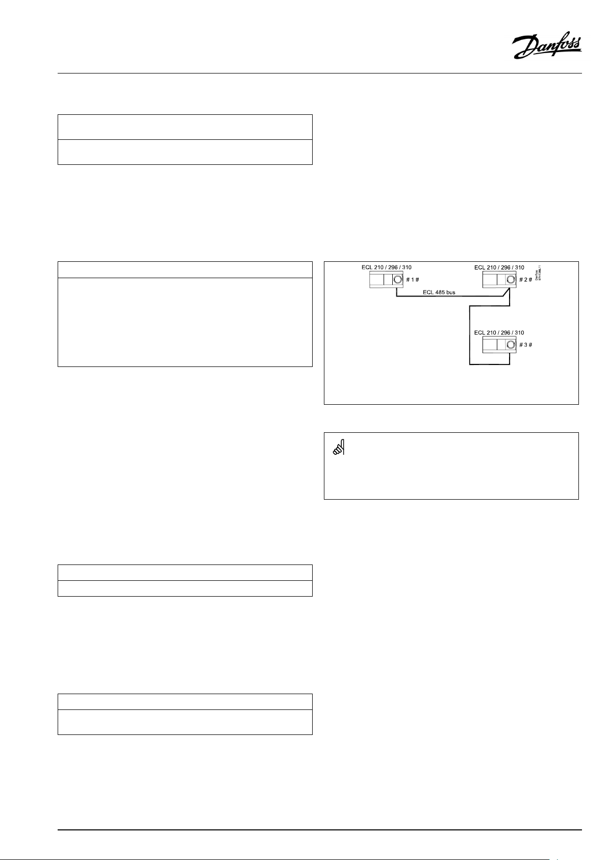
OperatingGuideECLComfort310,applicationP348
MENU>Settings>Returnlimit
Con.T,re.Tlim.(Constanttemperaturemode,return
temperaturelimitation)
The"Con.T ,ret.Tlimit"isthereturntemperaturelimitationvaluewhenthe
circuitissettooverridemodetype"Const.T"(=Constanttemperature).
SeeAppendix“ParameterIDoverview”
Value:Setthereturntemperaturelimitation
MENU>Settings>Returnlimit
DHW,ret.Tlimit
WhenanaddressedslaveisactiveinDHW-tankheating/charging,the
returntemperaturelimitationinthemastercanbeset.
Notes:
•Themastercircuitmustbesettoreactonthedesiredflowtemperature
intheslave(s).See"Demandoffset"(ID11017).
•Theslave(s)mustbesettosendits/theirdesiredflowtemperatureto
themaster.See"SenddesiredT"(ID1x500).
SeeAppendix“ParameterIDoverview”
OFF:
Noinfluencefromslaves.Thereturntemperature
limitationisrelatedtosettingsin"Returnlimit" .
Value:
Returntemperaturelimitationvaluewhenslaveisin
DHWtankheating/chargingoperation.
1x028
1x029
#1#=Master,exampleA266,address15
#2#=Slave,exampleA237,address9
#3#=Slave,exampleA367,address6
MENU>Settings>Returnlimit
HighToutX1(returntemp.limitation,highlimit,X-axis)
Settheoutdoortemperaturevalueforthelowreturntemperaturelimitation.
SeeAppendix“ParameterIDoverview”
ThecorrespondingYcoordinateissetin'LowlimitY1' .
MENU>Settings>Returnlimit
LowlimitY1(returntemp.limitation,lowlimit,Y-axis)
Setthereturntemperaturelimitationreferringtotheoutdoortemperature
valuesetin'HighToutX1' .
SeeAppendix“ParameterIDoverview”
SomeexamplesofapplicationswithDHW-tankheating/chargingare:
•A217,A237,A247,A367,A377
1x031
1x032
ThecorrespondingXcoordinateissetin'HighToutX1' .
VI.LV.G3.02
©Danfoss|2018.11|61
Page 62

OperatingGuideECLComfort310,applicationP348
MENU>Settings>Returnlimit
LowToutX2(returntemp.limitation,lowlimit,X-axis)
Settheoutdoortemperaturevalueforthehighreturntemperature
limitation.
SeeAppendix“ParameterIDoverview”
ThecorrespondingYcoordinateissetin'HighlimitY2'.
MENU>Settings>Returnlimit
HighlimitY2(returntemp.limitation,highlimit,Y-axis)
Setthereturntemperaturelimitationreferringtotheoutdoortemperature
valuesetin'LowToutX2' .
SeeAppendix“ParameterIDoverview”
ThecorrespondingXcoordinateissetin'LowToutX2' .
MENU>Settings>Returnlimit
Infl.-max.(returntemp.limitation-max.influence)
Determineshowmuchthedesiredflowtemperaturewillbeinfluencedifthe
returntemperatureishigherthanthecalculatedlimit.
1x033
1x034
1x035
Ifthe‘Infl. ’factoristoohighand/orthe‘ Adapt.time’toolow,thereis
ariskofunstablecontrol.
SeeAppendix“ParameterIDoverview”
Influencehigherthan0:
Thedesiredflowtemperatureisincreased,whenthereturn
temperaturegetshigherthanthecalculatedlimit.
Influencelowerthan0:
Thedesiredflowtemperatureisdecreased,whenthereturn
temperaturegetshigherthanthecalculatedlimit.
MENU>Settings>Returnlimit
Infl.-min.(returntemp.limitation-min.influence)
Determineshowmuchthedesiredflowtemperaturewillbeinfluencedifthe
returntemperatureislowerthanthecalculatedlimit.
SeeAppendix“ParameterIDoverview”
Influencehigherthan0:
Thedesiredflowtemperatureisincreased,whenthereturn
temperaturegetsbelowthecalculatedlimit.
Influencelowerthan0:
Thedesiredflowtemperatureisdecreased,whenthereturn
temperaturegetsbelowthecalculatedlimit.
Example
Thereturnlimitisactiveabove50°C.
Theinfluenceissetto-2.0.
Theactualreturntemperatureis2degreestoohigh.
Result:
Thedesiredflowtemperatureischangedby-2.0x2=-4.0degrees.
Normally,thissettingislowerthan0indistrictheatingsystemsto
avoidatoohighreturntemperature.
Typically,thissettingis0inboilersystemsbecauseahigherreturn
temperatureisacceptable(seealso'Infl.-min. ').
Example
1x036
Thereturnlimitisactivebelow50°C.
Theinfluenceissetto-3.0.
Theactualreturntemperatureis2degreestoolow.
Result:
Thedesiredflowtemperatureischangedby-3.0x2=-6.0degrees.
Normally,thissettingis0indistrictheatingsystemsbecausealower
returntemperatureisacceptable.
Typically,thissettingishigherthan0inboilersystemstoavoidatoo
lowreturntemperature(seealso'Infl.-max.').
62|©Danfoss|2018.11
VI.LV.G3.02
Page 63

OperatingGuideECLComfort310,applicationP348
MENU>Settings>Returnlimit
Adapt.time(adaptationtime)
Controlshowfastthereturntemperatureadaptstothedesiredreturn
temperaturelimit(Integrationcontrol).
SeeAppendix“ParameterIDoverview”
OFF:
Thecontrolfunctionisnotinfluencedbythe‘Adapt.
time’ .
Minor
Thedesiredtemperatureisadaptedquickly.
value:
Major
Thedesiredtemperatureisadaptedslowly.
value:
MENU>Settings>Returnlimit
Priority(priorityforreturntemp.limitation)
Choosewhetherthereturntemperaturelimitationshouldoverruletheset
min.flowtemperature‘Temp.min. ’.
SeeAppendix“ParameterIDoverview”
OFF:
ON:
Themin.flowtemperaturelimitisnotoverruled.
Themin.flowtemperaturelimitisoverruled.
1x037
Theadaptationfunctioncancorrectthedesiredflowtemperature
withmax.8K.
1x085
IfyouhaveaDHWapplication:
Pleasealsosee‘Paralleloperation’(ID11043).
IfyouhaveaDHWapplication:
Whendependentparalleloperationisinfunction:
•Desiredflowtemperaturefortheheatingcircuitwillbeminimum
limited,when"Priorityforreturntemperature"(ID1x085)isset
toOFF.
•Desiredflowtemperaturefortheheatingcircuitwillnotbe
minimumlimited,when"Priorityforreturntemperature"
(ID1x085)issettoON.
VI.LV.G3.02
©Danfoss|2018.11|63
Page 64

OperatingGuideECLComfort310,applicationP348
5.5Flow/powerlimit
Heatingcircuit
Afloworenergymetercanbeconnected(M-bussignal)totheECL
controllerinordertolimitthefloworconsumedpower.
Theflow/powerlimitationcanbebasedontheoutdoor
temperature.Typically,indistrictheatingsystemsahigherflowor
powerisacceptedatloweroutdoortemperatures.
Therelationshipbetweenthefloworpowerlimitsandtheoutdoor
temperatureissetintwocoordinates.
Theoutdoortemperaturecoordinatesaresetin'HighToutX1'
and'LowToutX2'.
Thefloworpowercoordinatesaresetin'LowlimitY1'and'High
limitY2' .Basedonthesesettings,thecontrollercalculatesthe
limitationvalue.
Whentheflow/powergetshigherthanthecalculatedlimit,the
controllergraduallyreducesthedesiredflowtemperaturetoobtain
anacceptablemax.floworpowerconsumption.
X
Y
#X1#
#X2#
#Y1#
#Y2#
=
Outdoortemperature
=
Limitation,floworpower
=
HighTout(1x119)
=
LowTout(1x118)
=
Lowlimit(1x117)
=
Highlimit(1x116)
MENU>Settings>Flow/powerlimit
Actual(actualfloworpower)
Thevalueistheactualfloworpowerbasedonthesignalfromflow/energy
meter.
=
X
Y
#1#
#2#
#3#
Ifthe‘Adapt.time’istoohigh,thereisariskofunstablecontrol.
Time
=
Floworpower
=
Floworpowerlimit
=
Actualfloworenergy
=
Desiredflowtemperature
64|©Danfoss|2018.11
VI.LV.G3.02
Page 65

OperatingGuideECLComfort310,applicationP348
MENU>Settings>Flow/powerlimit
Actuallimit
Thevalueistheactualfloworpowerlimitation,basedonoutdoor
temperatureandthesettingsin"HighToutX1","LowlimitY1" ,"LowTout
X2"and"HighlimitY2".
MENU>Settings>Flow/powerlimit
Inputtype
Choiceofinputtypefromflow/energymeter
SeeAppendix“ParameterIDoverview”
OFF:
EM1-
Noinput
Flow/energymetersignalfromM-bus.
EM5:
MENU>Settings>Flow/powerlimit
Adapt.time(adaptationtime)
Controlshowfasttheflow/powerlimitationadaptstothedesired
limitation.
SeeAppendix“ParameterIDoverview”
OFF:
Thecontrolfunctionisnotinfluencedbythe‘Adapt.
time’ .
Minor
Thedesiredtemperatureisadaptedquickly.
value:
Major
Thedesiredtemperatureisadaptedslowly.
value:
1x10⁹
1x112
Ifthe‘Adapt.time’istoolow,thereisariskofunstablecontrol.
MENU>Settings>Flow/powerlimit
Filterconstant
Thevalueofthefilterconstantdeterminesthedampeningofthemeasured
value.
Thehigherthevalue,themoredampening.
Bythis,atooquickchangeofthemeasuredvaluecanbeavoided.
SeeAppendix“ParameterIDoverview”
Minor
Lowerdampening
value:
Major
Higherdampening
value:
VI.LV.G3.02
1x113
©Danfoss|2018.11|65
Page 66

OperatingGuideECLComfort310,applicationP348
MENU>Settings>Flow/powerlimit
Units
Choiceofunitsformeasuredvalues.
SeeAppendix“ParameterIDoverview”
Flowvaluesareexpressedasl/horm³/h
PowervaluesareexpressedaskW,MWorGW.
MENU>Settings>Flow/powerlimit
HighlimitY2(flow/powerlimitation,highlimit,Y-axis)
Settheflow/powerlimitationreferringtotheoutdoortemperatureset
in'LowToutX2' .
SeeAppendix“ParameterIDoverview”
ThecorrespondingXcoordinateissetin'LowToutX2' .
MENU>Settings>Flow/powerlimit
1x115
Listforsettingrangeof'Units':
l/h
m³/h
kW
MW
GW
1x116
LowlimitY1(flow/powerlimitation,lowlimit,Y-axis)
Settheflow/powerlimitationreferringtotheoutdoortemperaturesetin
'HighToutX1' .
SeeAppendix“ParameterIDoverview”
ThecorrespondingXcoordinateissetin'HighToutX1' .
MENU>Settings>Flow/powerlimit
LowToutX2(flow/powerlimitation,lowlimit,X-axis)
Settheoutdoortemperaturevalueforthehighflow/powerlimitation.
SeeAppendix“ParameterIDoverview”
ThecorrespondingYcoordinateissetin'HighlimitY2'.
MENU>Settings>Flow/powerlimit
HighToutX1(flow/powerlimitation,highlimit,X-axis)
Settheoutdoortemperaturevalueforthelowflow/powerlimitation.
1x117
Thelimitationfunctioncanoverruletheset'Temp.min'ofthedesired
flowtemperature.
1x118
1x119
SeeAppendix“ParameterIDoverview”
ThecorrespondingYcoordinateissetin'LowlimitY1' .
66|©Danfoss|2018.11
VI.LV.G3.02
Page 67

OperatingGuideECLComfort310,applicationP348
ParametersindicatedwithanIDno.like"1x607"meanauniversal
parameter.
xstandsforcircuit/parametergroup.
VI.LV.G3.02
©Danfoss|2018.11|67
Page 68

OperatingGuideECLComfort310,applicationP348
5.6Optimization
Thesection"Optimization"describesspecificapplicationrelated
issues.
Theparameters'Autosaving' ,'Boost','Optimizer','Totalstop'areall
relatedtoheatingmodeonly.
'Summer,cut-out'determine,atrisingoutdoortemperature,the
stopofheating.
ParametersindicatedwithanIDno.like"1x607"meanauniversal
parameter.
xstandsforcircuit/parametergroup.
68|©Danfoss|2018.11
VI.LV.G3.02
Page 69

OperatingGuideECLComfort310,applicationP348
MENU>Settings>Optimization
Autosaving(savingtemp.dependentonoutdoortemp.)
Belowthesetvaluefortheoutdoortemperature,thesavingtemperature
settinghasnoinfluence.Abovethesetvaluefortheoutdoortemperature,
thesavingtemperaturerelatestotheactualoutdoortemperature.The
functionisrelevantindistrictheatinginstallationsinordertoavoidabig
changeinthedesiredflowtemperatureafterasavingperiod.
SeeAppendix“ParameterIDoverview”
OFF:
Thesavingtemperaturedoesnotdependonthe
outdoortemperature;thereductionis100%.
Value:Thesavingtemperaturedependsontheoutdoor
temperature.Whentheoutdoortemperatureisabove
10°C,thereductionis100%.Thelowertheoutdoor
temperature,thelessthetemperaturereduction.
Belowthesetvalue,thesavingtemperaturesetting
hasnoinfluence.
Comforttemperature:
Thedesiredroomtemperaturein
Comfortmode
Savingtemperature:
ThedesiredroomtemperatureinSaving
mode
ThedesiredroomtemperaturesforComfortandSavingmodes
aresetinthedisplayoverviews.
1x011
=
X
Y
#1#
#2#
#3#
Example:
Actualoutdoortemperature(T.out):
DesiredroomtemperaturesettinginComfortmode:
DesiredroomtemperaturesettinginSavingmode:
Settingin‘Autosaving’:
Outdoortemperature(°C)
=
Desiredroomtemperature(°C)
=
Desiredroomtemperature(°C),Comfortmode
=
Desiredroomtemperature(°C),Savingmode
=
Autosavingtemperature(°C),ID11011
–5°C
22°C
16°C
–15°C
Theconditionfortheoutdoortemperatureinfluence:
T.out.influence=(10-T.out)/(10-setting)=
(10-(-5))/(10-(-15))=
15/25=0,6
ThecorrecteddesiredroomtemperatureinSavingmode:
T.room.ref.Saving+(T.out.influencex(T.room.ref.ComfortT.room.ref.Saving))
16+(0,6x(22-16))=19,6°C
=
X
Y
Outdoortemperature(°C)
=
Desiredroomtemperature(°C)
VI.LV.G3.02
©Danfoss|2018.11|69
Page 70

OperatingGuideECLComfort310,applicationP348
MENU>Settings>Optimization
Boost
Shortenstheheating-upperiodbyincreasingthedesiredflowtemperature
bythepercentageyouset.
SeeAppendix“ParameterIDoverview”
OFF:
Value:
Theboostfunctionisnotactive.
Thedesiredflowtemperatureisincreasedtemporarily
withthesetpercentage.
Inordertoshortentheheating-upperiodafterasaving
temperatureperiod,thedesiredflowtemperaturecanbeincreased
temporarily(max.1hour).Atoptimizingtheboostisactiveinthe
optimizationperiod('Optimizer').
IfaroomtemperaturesensororanECA30/31isconnected,the
booststopswhentheroomtemperatureisreached.
MENU>Settings>Optimization
Ramp(referenceramping)
Thetime(minutes)inwhichthedesiredflowtemperatureincreases
graduallytoavoidloadpeaksintheheatsupply.
SeeAppendix“ParameterIDoverview”
1x012
1x013
OFF:
Value:
Therampingfunctionisnotactive.
Thedesiredflowtemperatureisincreasedgraduallywith
thesetminutes.
Inordertoavoidloadpeaksinthesupplynetwork,theflow
temperaturecanbesettoincreasegraduallyafteraperiodwith
savingtemperature.Thiscausesthevalvetoopengradually.
X
Y
#1#
=
Time
=
Desiredflowtemperature
=
Rampingtime
=
Comforttemperature
=
Savingtemperature
70|©Danfoss|2018.11
VI.LV.G3.02
Page 71
OperatingGuideECLComfort310,applicationP348
MENU>Settings>Optimization
Optimizer(optimizingtimeconstant)
Optimizesthestartandstoptimesforthecomforttemperatureperiodto
obtainthebestcomfortatthelowestenergyconsumption.
Thelowertheoutdoortemperature,theearliertheheatingcut-in.Thelower
theoutdoortemperature,thelatertheheatingcut-out.
Theoptimizedheatingcut-outtimecanbeautomaticordisabled.The
calculatedstartandstoptimesarebasedonthesettingoftheoptimizing
timeconstant.
SeeAppendix“ParameterIDoverview”
Adjusttheoptimizingtimeconstant.
Thevalueconsistsofatwodigitnumber.Thetwodigitshavethe
followingmeaning(digit1=TableI,digit2=TableII).
OFF:
Nooptimization.Theheatingstartsandstopsatthe
timessetintheschedule.
10...59:
SeetablesIandII.
TableI:
1x014
Systemtype
LeftdigitHeataccumulationofthe
building
Radiator
1-light
systems
2-medium
3-heavy
Floorheating
4-medium
systems
5-heavy
TableII:
RightdigitDimensioningtemperatureCapacity
-0-50°Clarge
·
-1
-45°C
···
-5
-25°C
normal
···
MENU>Settings>Optimization
Basedon(optimizationbasedonroom/outdoortemp.)
Theoptimizedstartandstoptimecanbebasedoneitherroomoroutdoor
temperature.
SeeAppendix“ParameterIDoverview”
OUT:
Optimizationbasedonoutdoortemperature.Usethis
settingiftheroomtemperatureisnotmeasured.
ROOM:
Optimizationbasedonroomtemperature,ifmeasured.
-9
Dimensioningtemperature:
Thelowestoutdoortemperature(usuallydeterminedbyyoursystem
designerinconnectionwiththedesignoftheheatingsystem)atwhich
theheatingsystemcanmaintainthedesignedroomtemperature.
Example
Thesystemtypeisradiator,andtheheataccumulationofthebuilding
ismedium.
Theleftdigitis2.
Thedimensioningtemperatureis-25°C,andthecapacityisnormal.
Therightdigitis5.
Result:
Thesettingistobechangedto25.
1x020
-5°C
small
VI.LV.G3.02
©Danfoss|2018.11|71
Page 72

OperatingGuideECLComfort310,applicationP348
MENU>Settings>Optimization
Totalstop
Decidewhetheryouwantatotalstopduringthesavingtemperatureperiod.
1x021
SeeAppendix“ParameterIDoverview”
OFF:
Nototalstop.Thedesiredflowtemperatureisreduced
accordingto:
•desiredroomtemperatureinsavingmode
•autosaving
ON:
Thedesiredflowtemperatureisloweredtothesetvalue
in‘Frostpr. ’Thecirculationpumpisstoppedbutfrost
protectionisstillactive,see'PfrostT' .
Totalstop=OFF
Totalstop=ON
X
Y
=
Time
=
Desiredflowtemperature
=
Comforttemperature
=
Savingtemperature
=
Frostprotection
MENU>Settings>Optimization
Pre-stop(optimizedstoptime)
Disabletheoptimizedstoptime.
SeeAppendix“ParameterIDoverview”
OFF:
ON:
Theoptimizedstoptimeisdisabled.
Theoptimizedstoptimeisenabled.
Themin.flowtemperaturelimitation('Temp.min.')isoverruledwhen
'Totalstop'isON.
1x026
Example:OptimizationofComfortfrom07:00-22:00
=
X
#1#
#2#
#3#
#4#
#5#
Time
=
Schedule
=
Prestop=OFF
=
Prestop=ON
=
Optimizedstart
=
Optimizedstop
72|©Danfoss|2018.11
VI.LV.G3.02
Page 73

OperatingGuideECLComfort310,applicationP348
MENU>Settings>Optimization
Summer,cut-out(limitforheatingcut-out)
1x179
SeeAppendix“ParameterIDoverview”
TheheatingcanbeswitchedOFFwhentheoutdoortemperatureis
higherthanthesetvalue.Thevalveclosesandafterthepost-run
time,theheatingcirculationpumpstops.‘Temp.min.’willbe
overruled.
TheheatingsystemswitchesONagainwhentheoutdoor
temperatureandtheaccumulated(filtered)outdoortemperature
becomelowerthanthesetlimit.
Thisfunctioncansaveenergy.
Setthevalueforoutdoortemperatureatwhichyouwantthe
heatingsystemtoswitchOFF .
Summer,cut-out
=
X
Y
#1#
#2#
#3#
#4#
#5#
Time
=
Temperature
=
Actualoutdoortemperature
=
Cut-outtemperature(1x179)
=
Accummulated(filtered)outdoortemperature
=
Heatingenabled
=
Heatingdisabled
Theheatingcut-outisonlyactivewhenthecontrollermodeisin
scheduledoperation.Whenthecut-outvalueissettoOFF,thereis
noheatingcut-out.
VI.LV.G3.02
©Danfoss|2018.11|73
Page 74

OperatingGuideECLComfort310,applicationP348
5.7Controlparameters
ControlofvalvesM1andM2
Themotorizedcontrolvalvesarecontrolledbymeansof3-point
controlsignal.
M1isanON/OFFvalve.
M2isacontrolvalve.
Thewaterflowthroughthecontrolvalveismanagedbymeans
ofanelectricactuator.Thecombination"actuator"and"control
valve"isalsocalledmotorizedcontrolvalve.Theactuatorcanin
thiswaygraduallyincreaseordecreasetheflowinordertochange
thesuppliedenergy.Differenttypesofactuatorsareavailable.
Controlvalve
Themotorizedcontrolvalveisopenedgraduallywhentheflow
temperatureislowerthanthedesiredflowtemperatureandvice
versa.
3-pointcontrolledactuator:
Theelectricactuatorcontainsareversiblegear-motor.Electric
"open"and"close"signalscomefromtheelectronicoutputsofthe
ECLComfortcontrollerinordertomanagethecontrolvalve.The
signalsareintheECLComfortcontrollerexpressedas"Arrow-up"
(open)and"Arrow-down"(close)anddisplayedatthevalvesymbol.
Whentheflowtemperature(forexampleatS3)islowerthanthe
desiredflowtemperature,shortopen-signalscomefromtheECL
Comfortcontrollerinordertograduallyincreasetheflow.Bythis,
theflowtemperaturewillalignwiththedesiredtemperature.
Oppositely,whentheflowtemperatureishigherthanthedesired
flowtemperature,shortclose-signalscomefromtheECLComfort
controllerinordertograduallyreducetheflow.Again,theflow
temperaturealignswiththedesiredtemperature.
Neitheropen-signalsnorclose-signalswillcomeaslongastheflow
temperaturecorrespondstothedesiredtemperature.
74|©Danfoss|2018.11
VI.LV.G3.02
Page 75

OperatingGuideECLComfort310,applicationP348
ParametersindicatedwithanIDno.like"1x607"meanauniversal
parameter.
xstandsforcircuit/parametergroup.
MENU>Settings>Controlparameters
Xpactual
‘Xpactual’istheread-outoftheactualXp(proportionalband)basedon
thesupplytemperature.Xpisdeterminedbysettingsrelatedtothesupply
temperature.Typically,thehigherthesupplytemperature,thehighertheXp
mustbeinordertoachieveastabletemperaturecontrol.
Xpsettingrange:
5...250K
Fixedsupplytemperaturesettings:65°Cand90°C
Factorysettings:
(65,40)and(90,120)
Thismeansthatthe‘Xp’is40Kat65°Csupplytemperature,and
‘Xp’is120Kat90°C.
SetthedesiredXpvaluesatthetwofixedsupplytemperatures.
Ifthesupplytemperatureisnotmeasured(thesupplytemperature
sensorisnotconnected),theXpvalueatthesetting65°Cisused.
MENU>Settings>Controlparameters
Adapt.time(adaptationtime)
Whenthepumpiscontrolledatlowspeed(inpulsedmode)theregulation
canbedampened.Atoolowdampeningcanresultinunstabletemperature
regulation.
1x065
SeeAppendix“ParameterIDoverview”
Low
Lowdampening
value:
High
Highdampening
value:
MENU>Settings>Controlparameters
Anti-bac.ret.T(Anti-bacteria,returntemperature)
Whenanti-bacteriamodeisactiveintheDHWcircuit,theDHWcirculation
circuitcanrunatasettemperature.Thesettingof'Anti-bac.ret.T'willnot
causeachangeofthe'DesiredT'asanti-bacteriatemperature.
SeeAppendix“ParameterIDoverview”
VI.LV.G3.02
1x126
©Danfoss|2018.11|75
Page 76

OperatingGuideECLComfort310,applicationP348
MENU>Settings>Controlparameters
Voutmax.
Theoutputvoltagecanbelimitedtoamaximumvalue.
SeeAppendix“ParameterIDoverview”
Thevaluein%expressesthemaximumvoltagefortheoutputin
question.
MENU>Settings>Controlparameters
Voutmin.
Theoutputvoltagecanbelimitedtoaminimumvalue.
SeeAppendix“ParameterIDoverview”
Thevaluein%expressestheminimumvoltagefortheoutputin
question.
MENU>Settings>Controlparameters
1x165
Example
Asettingof60%meansthattheoutputvoltagewillbe6voltasa
maximum.
1x167
Example:
Asettingof20%meansthattheoutputvoltagewillbe2voltasa
minimum.
Thesetting'Reverseout'hasnoinfluenceonthe'Voutmax’or‘V
outmin'settings.
The'Voutmin'settinghashigherprioritythan'Voutmax' .
Reverseout
Theanalogoutput(0-10volt)canbearisingorafallingvoltageforrising
coolingdemand.
SeeAppendix“ParameterIDoverview”
OFF:
Theanalogoutputvoltagewillfallatarisingcooling
demand.
ON:
Theanalogoutputvoltagewillriseatarisingcooling
demand.
MENU>Settings>Controlparameters
Motorpr.(motorprotection)
Preventsthecontrollerfromunstabletemperaturecontrol(andresulting
actuatoroscillations).Thiscanoccuratverylowload.Themotorprotection
increasesthelifetimeofallinvolvedcomponents.
SeeAppendix“ParameterIDoverview”
OFF:
Value:
Motorprotectionisnotactivated.
Motorprotectionisactivatedafterthesetactivation
delayinminutes.
1x171
1x174
Recommendedforductsystemswithvariableload.
76|©Danfoss|2018.11
VI.LV.G3.02
Page 77

OperatingGuideECLComfort310,applicationP348
MENU>Settings>Controlparameters
Xp(proportionalband)
1x184
SeeAppendix“ParameterIDoverview”
Settheproportionalband.Ahighervaluewillresultinastablebut
slowcontroloftheflowtemperature.
Whenusingtheparameterforpumpspeedcontrol:
Ahighervaluewillresultinastable,butslowcontrolofthespeed.
MENU>Settings>Controlparameters
Tn(integrationtimeconstant)
1x185
SeeAppendix“ParameterIDoverview”
Setahighintegrationtimeconstant(inseconds)toobtainaslow
butstablereactiontodeviations.
Alowintegrationtimeconstantwillmakethecontrollerreactfast
butwithlessstability.
Whenusingtheparameterforpumpspeedcontrol:
Setahighervalue(inseconds)toobtainaslow,butstablereaction
todeviations.
Alowintegrationtimeconstantwillmakethecontrollerreactfast,
butwithlessstability.
MENU>Settings>Controlparameters
Mrun(runningtimeofthemotorizedcontrolvalve)
‘Mrun’isthetimeinsecondsittakesthecontrolledcomponenttomove
fromfullyclosedtofullyopenposition.
SeeAppendix“ParameterIDoverview”
Setthe‘Mrun’accordingtotheexamplesormeasuretherunning
timebymeansofastopwatch.
1x186
Howtocalculatetherunningtimeofamotorizedcontrolvalve
Therunningtimeofthemotorizedcontrolvalveiscalculatedusing
thefollowingmethods:
Seatedvalves
Runningtime=
Example:
Rotatingvalves
Runningtime=
Example:90degr.x2sec./degr.=180sec.
Thesetting"Mrun"isnotpresentwhenthevalveiscontrolledby
meansofa0-10voltsignal.
Valvestroke(mm)xactuatorspeed(sec./mm)
5.0mmx15sec./mm=75sec.
Turningdegreesxactuatorspeed(sec./degr.)
VI.LV.G3.02
©Danfoss|2018.11|77
Page 78

OperatingGuideECLComfort310,applicationP348
MENU>Settings>Controlparameters
Nz(neutralzone)
Whentheactualflowtemperatureiswithintheneutralzone,thecontroller
doesnotactivatethemotorizedcontrolvalve.
SeeAppendix“ParameterIDoverview”
Settheacceptableflowtemperaturedeviation.
Settheneutralzonetoahighvalueifyoucanacceptahigh
variationinflowtemperature.
Whenusingtheparameterforpumpspeedcontrol:
Settheacceptabletemperaturedeviation.
Whentheactualtemperatureiswithintheneutralzone,the
controllerdoesnotchangethepumpspeed.
.
MENU>Settings>Controlparameters
Min.act.time(min.activationtimegearmotor)
Themin.pulseperiodof20ms(milliseconds)foractivationofthegear
motor.
SeeAppendix“ParameterIDoverview”
1x187
Theneutralzoneissymmetricalaroundthedesiredflowtemperature
value,i.e.halfthevalueisaboveandhalfthevalueisbelowthis
temperature.
SettingexampleValuex20ms
1x189
240ms
10200ms
501000ms
MENU>Settings>Controlparameters
CWinfluence(ColdWaterinfluence)
Thecoldwaterflow(measuredbyColdWatermeterF1)caninfluencethe
DHWtemperaturecontrolbyoverridingthecontrolofthemotorizedcontrol
valve.Bythis,thetemperaturecontrolispro-activeandcompensatesfor
thedelaybeforetheflowtemperaturesensorS4measuresachangein
temperature.
Thevalueexpresseshowmany%of100liters/hourwilldoaninfluenceon
themotorizedcontrolvalve.
SeeAppendix“ParameterIDoverview”
Low
Minorinfluence
value:
High
Majorinfluence
value:
Thesettingshouldbekeptashighasacceptabletoincreasethe
lifetimeoftheactuator(gearmotor).
1x354
78|©Danfoss|2018.11
VI.LV.G3.02
Page 79

OperatingGuideECLComfort310,applicationP348
MENU>Settings>Controlparameters
Max.returnT
SettingthemaximumreturntemperaturevaluefortheDHWreturn
circulationatS9.
Whenthereturntemperaturegetslowerthanthesetvalue,thespeedofthe
DHWcirculationpumpcanbeincreased.
1x370
SeeAppendix“ParameterIDoverview”
Value:Desiredmax.returntemperature.
MENU>Settings>Controlparameters
PWMperiod
Whenthepumpiscontrolledatlowspeed(inpulsedmode)thesetvalue
reflectsthereactiontimeofthepump,thewaterflowandthetemperature
sensor.Atoolowvaluecanresultinunstabletemperatureregulation.
1x565
SeeAppendix“ParameterIDoverview”
Value:
Reactiontime
IfyouwanttotunethePIregulationprecisely,youcanusethefollowingmethod:
•Setthe‘Tn’(integrationtimeconstant)toitsmax.value(999sec.).
•Decreasethevalueforthe‘Xp’(proportionalband)untilthesystemstartshunting(i.e.getsunstable)withaconstantamplitude(it
mightbenecessarytoforcethesystembysettinganextremelowvalue).
•Findthecriticaltimeperiodonthetemperaturerecorderoruseastopwatch.
Temp.
Criticaltimeperiod
Time
Thiscriticaltimeperiodwillbecharacteristicforthesystem,andyoucanevaluatethesettingsfromthiscriticalperiod.
‘Tn’=
0.85xcriticaltimeperiod
‘Xp’=
2.2xproportionalbandvalueinthecriticaltimeperiod
Iftheregulationseemstobetooslow,youcandecreasetheproportionalbandvalueby10%.Makesurethereisaconsumption
whenyousettheparameters.
VI.LV.G3.02
©Danfoss|2018.11|79
Page 80

OperatingGuideECLComfort310,applicationP348
5.8Flowmeter
Aflowmeter,F1,measurestheColdWaterflowtothe
heat-exchanger.Thesignalformispulses.Thepulsesareapplied
to"Pulsein1"ontheECA32/35module.
Thewaterflowcanbedisplayedinl/h(liters/hour)orm3/h
(cubicmeters/hour).
ParametersindicatedwithanIDno.like"1x607"meanauniversal
parameter.
xstandsforcircuit/parametergroup.
MENU>Settings>Flowmeter
Actual
Actualcoldwaterflow.
Thevalueisbasedonthesetting"Pulse"(1x114)andappliedpulsesignal.
MENU>Settings>Flowmeter
Pulse
Thevaluetellshowmanypulsesfromtheflowmeterarerelatedtooneml
(milli-liter)orl(liter).
Thesettingdeterminestheread-outvaluein"Actual" .
Anexample:Value20meansthat20pulsesrepresent1milli-literor1liter.
1-9999:
Numberofpulsestorepresentonemilli-literoroneliter
1x114
80|©Danfoss|2018.11
VI.LV.G3.02
Page 81

OperatingGuideECLComfort310,applicationP348
MENU>Settings>Flowmeter
Units
Settingtheunit(milli-literorliter)forthepulsebasisanddesiredunit(l/hor
m3/h)fortheread-outofactualflow.
Example1for"Pulse"and"Unit"settings:
1x115
Pulse
Units
75
ml,l/h
75pulsesfromflowmeterrepresents1ml(milli-liter)
Read-outofactualflowwillbeexpressedasl/h(litersperhour)
Ifappliedpulseshaveafrequencyof8Hz(8pulsespersecond)
theread-outofactualflowwillbe:
Literx3600x8/75=384l/h
Example2for"Pulse"and"Unit"settings:
Pulse
Units
75
l,l/h
75pulsesfromflowmeterrepresents1l(liter)
Read-outofactualflowwillbeexpressedasl/h(litersperhour)
Ifappliedpulseshaveafrequencyof8Hz(8pulsespersecond)
theread-outofactualflowwillbe:
Milli-literx3600x8/75=384ml/h=0.384l/h
Example3for"Pulse"and"Unit"settings:
Pulse
Units
75
ml,m3/h
75pulsesfromflowmeterrepresents1ml(milli-liter)
Read-outofactualflowwillbeexpressedasm3/h(cubic
metersperhour)
Ifappliedpulseshaveafrequencyof8Hz(8pulsespersecond)
theread-outofactualflowwillbe:
Milli-literx3600x8/75=384ml/h
=0.384l/h
=0.000384m3/h
=0.0m3/h
Example4for"Pulse"and"Unit"settings:
Pulse
Units
75
l,m3/h
75pulsesfromflowmeterrepresents1l(liter)
Read-outofactualflowwillbeexpressedasm3/h(cubic
metersperhour)
Ifappliedpulseshaveafrequencyof8Hz(8pulsespersecond)
theread-outofactualflowwillbe:
Literx3600x8/75=384l/h
=384l/h
=0.384m3/h
=0.4m3/h
VI.LV.G3.02
©Danfoss|2018.11|81
Page 82

OperatingGuideECLComfort310,applicationP348
5.9Application
Thesection"Application"describesspecificapplicationrelated
issues.
Someoftheparameterdescriptionsareuniversalfordifferent
applicationkeys.
ParametersindicatedwithanIDno.like"1x607"meanauniversal
parameter.
xstandsforcircuit/parametergroup.
MENU>Settings>Application
ECAaddr.(ECAaddress,choiceofRemoteControlUnit)
Decidestheroomtemperaturesignaltransferandcommunicationwiththe
RemoteControlUnit.
SeeAppendix“ParameterIDoverview”
OFF:
NoRemoteControlUnit.Onlyroomtemperaturesensor,
ifany.
A:
B:
RemoteControlUnitECA30/31withaddressA.
RemoteControlUnitECA30/31withaddressB.
1x010
TheRemoteControlUnitmustbesetaccordingly(AorB).
82|©Danfoss|2018.11
VI.LV.G3.02
Page 83

OperatingGuideECLComfort310,applicationP348
MENU>Settings>Application
Demandoffset
Thedesiredflowtemperatureinheatingcircuit1canbeinfluencedbythe
demandforadesiredflowtemperaturefromanothercontroller(slave)or
anothercircuit.
SeeAppendix“ParameterIDoverview”
OFF:
Thedesiredflowtemperatureincircuit1isnot
influencedbythedemandofanyothercontroller(slave
orcircuit2).
Value:
Thedesiredflowtemperatureisincreasedbytheset
valuein‘Demandoffset’ ,ifthedemandoftheslave/
circuit2ishigher.
Heatingapplication
1x017
=
X
Y
#1#
#2#
#3#
Time
=
Desiredflowtemperatures
=
Demandoffset
=
Desiredflowtemperature,master
=
Desiredflowtemperature,slave
MENU>Settings>Application
Pexercise(pumpexercise)
Exercisesthepumptoavoidblockinginperiodswithoutheating/cooling
demand.
Thefunctionof‘Demandoffset’cancompensateforheatlosses
betweenmasterandslavecontrolledsystems.
'Demandoffset'withavalueistobeusedintheMastercontrolleronly.
Whensetting"Demandoffset"toavalue,thereturntemperature
limitationwillreactaccordingtothehighestlimitationvalue(Heating
/DHW).
1x022
SeeAppendix“ParameterIDoverview”
OFF:
ON:
Thepumpexerciseisnotactive.
ThepumpisswitchedONfor1minuteeverythirddayat
noon(12:14hours).
VI.LV.G3.02
©Danfoss|2018.11|83
Page 84

OperatingGuideECLComfort310,applicationP348
MENU>Settings>Application
Mexercise(valveexercise)
Exercisesthevalvetoavoidblockinginperiodswithoutheating/cooling
demand.
SeeAppendix“ParameterIDoverview”
OFF:
ON:
Thevalveexerciseisnotactive.
Thevalveopensfor7minutesandclosesfor7minutes
everythirddayatnoon(12:00hours).
MENU>Settings>Application
Ppost-run
Heatingapplications:
ThecirculationpumpintheheatingcircuitcanbeONforanumberof
minutes(m)afterheatingstop.Heatingstopiswhenthedesiredflow
temperaturegetslowerthanthesettingin'PheatT'(IDno.1x078).
Coolingapplications:
ThecirculationpumpinthecoolingcircuitcanbeONforanumberof
minutes(m)aftercoolingstop.Coolingstopiswhenthedesiredflow
temperaturegetshigherthanthesettingin'PcoolT'(IDno.1x070).
ThisPpost-runfunctioncanutilizetheremainingenergyinforexamplea
heatexchanger.
SeeAppendix“ParameterIDoverview”
1x023
1x040
0:
Thecirculationpumpstopsimmediatelyafterheating
orcoolingstop.
Value:
ThecirculationpumpisONforthesettimeafterheating
orcoolingstop.
MENU>Settings>Application
Pdemand
Thecirculationpumpinthemastercircuitcanbecontrolledinrelationto
themastercircuit'sdemandorslavecircuit'sdemand.
SeeAppendix“ParameterIDoverview”
Heatingapplications:
OFF:
ThecirculationpumpisONwhenthedesiredflow
temperatureintheheatingcircuitishigherthanthe
valuesetin'PheatT'.
ON:
ThecirculationpumpisONwhenthedesiredflow
temperaturefromslavesishigherthanthevaluesetin
'PheatT'.
Coolingapplications:
OFF:
ThecirculationpumpisONwhenthedesiredflow
temperatureinthecoolingcircuitislowerthanthevalue
setin'PcoolT'.
ON:
ThecirculationpumpisONwhenthedesiredflow
temperaturefromslavesislowerthanthevaluesetin
'PcoolT'.
1x050
Thecirculationpumpisalwayscontrolledaccordingtofrostprotection
conditions.
84|©Danfoss|2018.11
VI.LV.G3.02
Page 85

OperatingGuideECLComfort310,applicationP348
MENU>Settings>Application
DHWpriority(closedvalve/normaloperation)
Theheatingcircuitcanbeclosedwhenthecontrolleractsasslaveandwhen
DHWheating/chargingisactiveinthemaster.
SeeAppendix“ParameterIDoverview”
OFF:
Theflowtemperaturecontrolremainsunchanged
duringactiveDHWheating/charginginthemaster
controller.
ON:
Thevalveintheheatingcircuitisclosed*duringactive
DHWheating/charginginthemastercontroller.
*Thedesiredflowtemperatureissettothevaluesetin
‘Frostpr.T’
MENU>Settings>Application
PfrostT(circulationpump,frostprotectiontemp.)
Frostprotection,basedontheoutdoortemperature.
Whentheoutdoortemperaturegetsbelowthesettemperaturevaluein‘P
frostT’ ,thecontrollerautomaticallyswitchesONthecirculationpump(for
exampleP1orX3)toprotectthesystem.
SeeAppendix“ParameterIDoverview”
OFF:
Value:
Nofrostprotection.
CirculationpumpisONwhentheoutdoortemperature
isbelowthesetvalue.
1x052
Thissettingmustbeconsideredifthiscontrollerisaslave.
1x077
Undernormalconditions,yoursystemisnotfrostprotectedifyour
settingisbelow0°CorOFF.
Forwater-basedsystems,asettingof2°Cisrecommended.
Iftheoutdoortemperaturesensorisnotconnectedandthefactory
settinghasnotbeenchangedto'OFF' ,thecirculationpumpisalways
ON.
MENU>Settings>Application
PheatT(heatdemand)
Whenthedesiredflowtemperatureisabovethesettemperaturein‘PheatT’ ,
thecontrollerautomaticallyswitchesONthecirculationpump.
1x078
SeeAppendix“ParameterIDoverview”
Value:
ThecirculationpumpisswitchedONwhenthedesired
flowtemperatureisabovethesetvalue.
MENU>Settings>Application
Frostpr .T(frostprotectiontemp.)
SetthedesiredflowtemperatureattemperaturesensorS3toprotectthe
systemagainstfrost(atheatingcut-out,totalstopetc.).
WhenthetemperatureatS3getslowerthanthesetting,themotorized
controlvalveopensgradually.
1x093
SeeAppendix“ParameterIDoverview”
Thevalveisfullyclosedaslongasthepumpisnotswitchedon.
Thefrostprotectiontemperaturecanalsobesetinyourfavorite
displaywhenthemodeselectorisinfrostprotectionmode.
VI.LV.G3.02
©Danfoss|2018.11|85
Page 86

OperatingGuideECLComfort310,applicationP348
Overridemodefunctions:
ThefollowingsettingsdescribethefunctioningeneralfortheECL
Comfort210/296/310series.Theexplainedmodesaretypical
andnotapplicationrelated.Theymightdifferfromtheoverride
modesinyourapplication.
MENU>Settings>Application
Ext.input(externaloverride)
Choosetheinputfor'Ext.input'(externaloverride).Bymeansofaswitch
thecontrollercanbeoverriddento‘Comfort’,'Saving' ,'Frostprotection'or
'Constanttemperature'mode.
1x141
SeeAppendix“ParameterIDoverview”
OFF:
S1...S16:
Noinputshavebeenselectedforexternaloverride.
Inputselectedforexternaloverride.
IfS1...S6ischosenasoverrideinput,theoverrideswitchmusthave
gold-platedcontacts.
IfS7...S16ischosenasoverrideinput,theoverrideswitchcanbea
standardcontact.
Seethedrawingsforconnectionexamplesofoverrideswitchand
overriderelaytoinputS8.
S7...S16arerecommendedforoverrideswitch.
Example:Connectionofanoverrideswitch
Example:Connectionofanoverriderelay
IfECA32ismounted,also11...S16canbeused.
IfECA35ismounted,alsoS11orS12canbeused.
Chooseonlyanunusedinputforoverride.Ifanalreadyusedinputis
appliedforoverride,thefunctionalityofthisinputisalsoneglected.
Seealso‘Ext.mode’.
86|©Danfoss|2018.11
VI.LV.G3.02
Page 87

OperatingGuideECLComfort310,applicationP348
MENU>Settings>Application
Ext.mode(externaloverridemode)
ThemodeoverridecanbeactivatedforSaving,Comfort,Frostpr.or
ConstantTmode.
Foroverride,thecontrollermodemustbeinscheduledmode.
SeeAppendix“ParameterIDoverview”
Chooseanoverridemode:
SAVING:
Thecircuitinquestionisinsavingmodewhenthe
overrideswitchisclosed.
COMFORT:
Thecircuitinquestionisincomfortmodewhenthe
overrideswitchisclosed.
FROSTPR.:
TheheatingorDHWcircuitcloses,butisstillfrost
protected.
CONSTANTT:
Thecircuitinquestioncontrolsaconstant
temperature*)
*)
Seealso'DesiredT'(1x004),settingofdesiredflow
temperature(MENU>Settings>Flowtemperature)
Seealso'Con.T,ret.Tlim. '(1x028),settingofreturn
temperaturelimitation(MENU>Settings>Return
limit)
Theprocessdiagramsshowthefunctionality.
1x142
Seealso‘Ext.input’.
Example:OverridetoComfortmode
#1#=Overrideswitch(notactivated/activated)
#2#=Functionmode(Schedule/Comfort)
#3#=Time
Example:OverridetoSavingmode
#1#=Overrideswitch(notactivated/activated)
#2#=Functionmode(Schedule/Saving)
#3#=Time
Theresultofoverrideto'Saving'modedependsonthesettingin
'Totalstop'.
Totalstop=OFF:Heatingreduced
Totalstop=ON:Heatingstopped
VI.LV.G3.02
©Danfoss|2018.11|87
Page 88

OperatingGuideECLComfort310,applicationP348
Example:OverridetoFrostprotectionmode
#1#=Overrideswitch(notactivated/activated)
#2#=Functionmode(Schedule/Frostpr.)
#3#=Time
Example:OverridetoConstanttemperaturemode
#1#=Overrideswitch(notactivated/activated)
#2#=Functionmode(Schedule/Const.T)
#3#=Time
The"Const.T"valuecanbeinfluencedby:
•temp.max.
•temp.min.
•roomtemp.limit
•returntemp.limit
•flow/powerlimit
88|©Danfoss|2018.11
VI.LV.G3.02
Page 89

OperatingGuideECLComfort310,applicationP348
MENU>Settings>Application
SenddesiredT
Whenthecontrolleractsasaslavecontrollerinamaster/slavesystem,
informationaboutthedesiredflowtemperaturecanbesenttothemaster
controllerviatheECL485bus.
Stand-alonecontroller:
Sub-circuitscansendthedesiredflowtemperaturetothemastercircuit.
SeeAppendix“ParameterIDoverview”
OFF:
Informationaboutthedesiredflowtemperatureisnot
senttothemastercontroller.
ON:
Informationaboutthedesiredflowtemperatureissent
tothemastercontroller.
1x500
Inthemastercontroller,'Demandoffset'mustbesettoavalueinorder
toreactonadesiredflowtemperaturefromaslavecontroller.
Whenthecontrolleractsasaslave,itsaddressmustbe1,2,3...9in
ordertosendthedesiredtemperaturetothemaster(seethesection
‘Miscellaneous’ ,‘Severalcontrollersinthesamesystem’).
VI.LV.G3.02
©Danfoss|2018.11|89
Page 90

OperatingGuideECLComfort310,applicationP348
5.10Heatcut-out
MENU>Settings>Heatcut-out
Thesetting“Summercut-out”under“Optimization”fortheheating
circuitinquestiondeterminesaheatingcut-outwhentheoutdoor
temperatureexceedsthesetvalue.
Afilteringconstantforcalculatingtheaccumulatedoutdoor
temperatureisinternallysettoavalueof"250".Thisfiltering
constantrepresentsanaveragebuildingwithsolidouterandinner
walls(bricks).
Anoptionfordifferentiatedcut-outtemperatures,basedona
setsummerperiod,canbeutilizedinordertoavoiddiscomfort
atfallingoutdoortemperature.Furthermore,separatefiltering
constantscanbeset.
ThefactorysetvaluesforSummerperiodstartandWinterperiod
startaresettosamedate:May,20(Date=20,Month=5).
Thismeans:
•"Differentiatedcut-outtemperatures"aredisabled(notactive)
•Separate"Filteringconstant"valuesaredisabled(notactive)
Inordertoenabledifferentiated
•cut-outtemperaturebasedonsummer/winterperiod
•filteringconstants
thestartdatesfortheperiodsmustbedifferent.
90|©Danfoss|2018.11
VI.LV.G3.02
Page 91

OperatingGuideECLComfort310,applicationP348
5.10.1Differentiatedheatcut-out
Tosetdifferentiatedcut-outparametersforaheatingcircuitfor
“Summer”and“Winter”goto“Heatcut-out”:
(MENU>Settings>Heatcut-out)
Thisfunctionisactivewhenthedatesfor“Summer”and“Winter”
aredifferentinthe“Heatcut-out”menu.
ParametersindicatedwithanIDno.like"1x607"meanauniversal
parameter.
xstandsforcircuit/parametergroup.
MENU>Settings>Heatcut-out
Extendedheatcut-outsetting
ParameterIDSettingrange
Summerday
Summermonth
Summercut-out
Summerfilter
1x393
1x392
1x179
1x395
**
**
**
**
Factory
setting
SeeAppendix“ParameterIDoverview”
MENU>Settings>Heatcut-out
Extendedwintercut-outsetting
ParameterIDSettingrange
Winterday
Wintermonth
Wintercut-out
Winterfilter
1x397
1x396
1x398
1x399
**
**
**
**
Factory
SeeAppendix“ParameterIDoverview”
Theabovesettingsofthedatesforthecut-outfunctionareonly
tobedoneintheheatingcircuit1andarevalidforotherheating
circuitsinthecontrolleraswell,ifapplicable.
Thecut-outtemperaturesaswellasthefilterconstantaretobeset
individuallyperheatingcircuit.
setting
Theheatingcut-outisonlyactivewhenthecontrollermodeisin
scheduledoperation.Whenthecut-outvalueissettoOFF,thereis
noheatingcut-out.
VI.LV.G3.02
©Danfoss|2018.11|91
Page 92
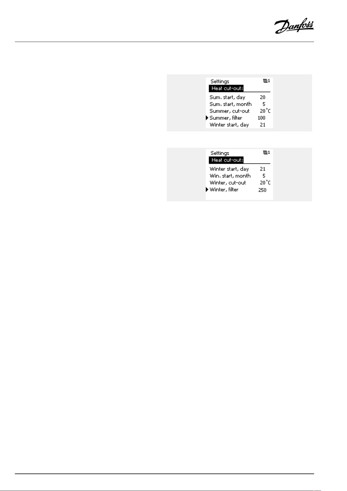
OperatingGuideECLComfort310,applicationP348
5.10.2Summer/winterfilterconstant
Thefilterconstantof250isapplicableforaveragebuildings.A
filterconstantof1iscloseswitchingaccordingtoactualoutdoor
temperaturemeaninglowfiltering(very“light”building).
Afilterconstantof300isthentobechosenifabigfilteringis
needed(veryheavybuilding).
Forheatingcircuitswheretheheatcut-outisdemandedaccording
tothesameoutdoortemperatureforthewholeyear,butdifferent
filteringiswanted,differentdateshavetobesetinthe“Heat
cut-out”menuenablingaselectionofafilterconstantdifferent
fromthefactorysetting.
Thesedifferentvalueshavetobesetinboththe“Summer”and
“Winter”menu.
92|©Danfoss|2018.11
VI.LV.G3.02
Page 93

OperatingGuideECLComfort310,applicationP348
5.11Tanktemperature
MENU>Settings>Tanktemperature
Demandoffset(fortank(buffer)temperature)
ThedesiredtanktemperatureatS6isincreasedwithanumberofdegrees,
basedonthedesiredDHWtemperatureatS4.
SeeAppendix“ParameterIDoverview”
Value:
Setthenumberofdegreestoincreasethedesiredtank
(buffer)temperature.
MENU>Settings>Tanktemperature
Temp.min.(Minimumtemperature)
Settingthemin.tank(buffer)temperatureforthesystem.Thedesiredtank
temperaturewillnotbelowerthanthissetting.
SeeAppendix“ParameterIDoverview”
Value:
Minimumtank(buffer)temperature
MENU>Settings>Tanktemperature
Temp.max.(Maximumtemperature)
Settingthemax.tank(buffer)temperatureforthesystem.Thedesiredtank
temperaturewillnotbehigherthanthissetting.
1x017
1x177
1x178
SeeAppendix“ParameterIDoverview”
Value:
Maximumtank(buffer)temperature
VI.LV.G3.02
©Danfoss|2018.11|93
Page 94

OperatingGuideECLComfort310,applicationP348
MENU>Settings>Tanktemperature
Stopdifference
Settingthenumberofdegreesbelowthedesiredtank(buffer)temperature,
andmeasuredbythelowertanktemperaturesensor,thatwillstopthetank
charging.
NOTE:Whenconditionforstop,relatedtothelowertanktemperature
sensor,ispresent,thechargingstopisdonewhentheuppertank
temperaturesensormeasuresahighertemperaturethanthestartdifference
level.
SeeAppendix“ParameterIDoverview”
Value:
Differenceforcharging-stop
1x194
=
X
#1#
#2#
#3#
#4#
#5#
#6#
Example:
Desiredtank(buffer)temp.=
Desiredtank(buffer)temp.=
Stopdifference:
Result:
Thetankchargingstopswhenthetemperaturemeasuredbythe
lowertanktemperaturesensorS8getshigherthan51°C.
Time
=
Startdifference(ID12195)
=
DesiredDHWtemperature
=
Stopdifference(ID12194)
=
Actualtanktemperature,upper(S6)
=
Actualtanktemperature,lower(S8)
=
Tankchargingactivity
DesiredDHWtemp.+
'Demandoffset'
55°C+4K=59°C
-8K
Whenonlyonetanktemperaturesensor(S6)isused,the'Stop
difference'valueshouldtypicallybeapositivevalue.
94|©Danfoss|2018.11
VI.LV.G3.02
Page 95

OperatingGuideECLComfort310,applicationP348
MENU>Settings>Tanktemperature
Startdifference
Settingthenumberofdegreesbelowthedesiredtank(buffer)temperature,
andmeasuredbytheuppertanktemperaturesensor,thatwillstartthe
tankcharging.
SeeAppendix“ParameterIDoverview”
Value:
Differenceforcharging-start
1x195
=
X
#1#
#2#
#3#
#4#
#5#
Example:
Desiredtank(buffer)temp.=
Desiredtank(buffer)temp.=
Startdifference:
Time
=
Demandoffset(ID12017)
=
DesiredDHWtemperature
=
Startdifference(ID12195)
=
Actualtanktemperature(S6)
=
Tankchargingactivity
DesiredDHWtemp.+
'Demandoffset'
55°C+4K=59°C
-3K
Result:
Thetankchargingstartswhenthetemperaturemeasuredbythe
tanktemperaturesensor(upper)islowerthan56°C.
VI.LV.G3.02
©Danfoss|2018.11|95
Page 96

OperatingGuideECLComfort310,applicationP348
5.12Anti-bacteria
OnselecteddaysduringtheweektheDHWtemperaturecan
beincreasedinordertoneutralizebacteriaintheDHWsystem.
ThedesiredDHWtemperature'DesiredT'(typically80°C)willbe
presentfortheselectedday(s)andduration.
Theanti-bacteriafunctionisnotactiveinfrostprotectionmode.
=
X
Y
#1#
#2#
#3#
#4#
#5#
Time
=
DesiredDHWtemperature
=
Duration
=
DesiredAnti-bacteriatemperaturevalue
=
DesiredAnti-bacteriatemperature
=
DesiredDHWtemperaturevalue
=
Starttime
TheDHWcirculationcircuitcanalsobesettocontrolan
Anti-bacteriatemperature.Thiscontrolisactiveinparalleltothe
DHWrelatedAnti-bacteriafunction.
Duringtheanti-bacteriaprocess,thereturntemperaturelimitationis
notactive.
96|©Danfoss|2018.11
VI.LV.G3.02
Page 97

OperatingGuideECLComfort310,applicationP348
MENU>Settings>Anti-bacteria
Day
Select(mark)theday(s)oftheweekwheretheanti-bacteriafunctionmust
beactive.
=
Monday
M
=
Tuesday
T
=
Wednesday
W
=
Thursday
T
=
Friday
F
=
Saturday
S
=
Sunday
S
MENU>Settings>Anti-bacteria
Starttime
Setthestarttimefortheanti-bacteriafunction.
MENU>Settings>Anti-bacteria
Duration
Settheduration(minutes)fortheanti-bacteriafunction.
MENU>Settings>Anti-bacteria
DesiredT
SetthedesiredDHWtemperaturefortheanti-bacteriafunction.
SeeAppendix“ParameterIDoverview”
OFF:
Value:
Theanti-bacteriafunctionisnotactive.
DesiredDHWtemperatureduringtheanti-bacteria
functionperiod.
VI.LV.G3.02
©Danfoss|2018.11|97
Page 98

OperatingGuideECLComfort310,applicationP348
5.13Alarm
Thesection"Alarm"describesspecificapplicationrelatedissues.
ApplicationP348offersdifferenttypesofalarms:
Type:
1
1
2
2
Thealarmfunctionsactivatethealarmbellsymbol.
ThealarmfunctionsactivateA1,whichisrelay6intheECLComfort
310controller:
Thealarmrelaycanactivatealamp,ahorn,aninputtoanalarm
transmittingdeviceetc.
Thealarmsymbol/relayisactivated:
•(type1)aslongasthealarmreasonispresent(automaticreset).
•(type2)evenifthealarmreasondisappearsagain(manual
reset).
Alarmtype1(flowtemperature):
Iftheflowtemperaturedeviatesmorethanthesetdifferencesfrom
thedesiredflowtemperature,thealarmsymbol/relaywillbe
activatedafterasetdelay.
Iftheflowtemperaturebecomesacceptable,thealarmsymbol/
relaywillbede-activated.
Description:
Actualflowtemperaturediffersfromthe
desiredflowtemperature.
ActualpressureatS15and/orS16exceeds
asethigh/lowlevel.
Anti-bacteriatemperatureisnotreached
withinthe"Duration"time.
Disconnectionorshort-circuitingofa
temperaturesensororitsconnection.
Alarmtype1(pressure):
IfthepressureatS15and/orS16goesbeloworabovesetlevels,
thealarmsymbol/relaywillbeactivatedafterasetdelay.
Ifthepressurebecomesacceptable,thealarmsymbol/relaywill
bede-activated.
Alarmtype2(Anti-bacteria):
Iftheanti-bacteriatemperaturewasnotachievedwithinthe
"Duration",thealarmsymbol/relaywillbeactivated.Thealarm
mustbemanuallyreset.
Alarmtype2(temperaturesensors):
Selectedtemperaturesensorscanbemonitored.
Shouldtheconnectiontothetemperaturesensorbedisconnected,
short-circuitedorthesensorgetsdefective,thealarmsymbol
/relaywillbeactivated.Inthe"Rawinputoverview"(MENU>
Commoncontrollersettings>System>Rawinputoverview)the
sensorinquestionismarkedandthealarmcanbereset.
98|©Danfoss|2018.11
VI.LV.G3.02
Page 99

OperatingGuideECLComfort310,applicationP348
Alarmoverview,list:
Alarm
no.:
2
3
7
8
9
32
Description:
Temp.monitor,circuit1
Temp.monitor,circuit2
Pressure
Anti-bacteria,circuit3
Pressure
Tsensordefect
Alarm
type:
1
1
1
1
1
2
Sensor
ref.:
S3
S4
S15
S9
S16
all
Tofindthereasonforanalarm:
•selectMENU
•select‘Alarm’
•select‘Alarmoverview’ .A"bell"willbeshownatthealarmin
question.
Alarmoverview(example):
2:Max.temp.
3:Temp.monitor
32:Tsensordefect
Thenumbersinthe'Alarmoverview'refertothealarmnumber
intheModbuscommunication.
Toresetanalarm:
Whenthe"bell"ispresenttotherightofthealarmline,placethe
cursoratthealarmlineinquestionandpressthedial.
Toresetalarm32:
MENU>Commoncontrollersettings>System>Rawinput
overview:Thesensorinquestionismarkedandthealarmcanbe
reset.
MENU>Settings>Alarm
Upperdifference
Thealarmisactivatediftheactualflow/ducttemperatureincreasesmore
thanthesetdifference(acceptabletemperaturedifferenceabovethedesired
flow/ducttemperature).Seealso'Delay' .
SeeAppendix“ParameterIDoverview”
OFF:
Value:
Therelatedalarmfunctionisnotactive.
Thealarmfunctionisactiveiftheactualtemperature
getsabovetheacceptabledifference.
1x147
Upperdifference
=
X
=
Y
=
#1#
=
#2#
Time
Temperature
Upperdifference
Desiredflowtemperature
VI.LV.G3.02
©Danfoss|2018.11|99
Page 100

OperatingGuideECLComfort310,applicationP348
MENU>Settings>Alarm
Lowerdifference
Thealarmisactivatediftheactualflow/ducttemperaturedecreasesmore
thanthesetdifference(acceptabletemperaturedifferencebelowthedesired
flow/ducttemperature).Seealso'Delay' .
SeeAppendix“ParameterIDoverview”
1x148
Lowerdifference
OFF:
Value:
Therelatedalarmfunctionisnotactive.
Thealarmfunctionisactiveiftheactualtemperature
getsbelowtheacceptabledifference.
MENU>Settings>Alarm
Delay,example
Ifanalarmconditionfromeither'Upperdifference'or'Lowerdifference'is
presentforalongertimethanthesetdelay(inminutes),thealarmfunction
isactivated.
SeeAppendix“ParameterIDoverview”
Value:
Thealarmfunctionwillbeactivatedifthealarm
conditionremainsafterthesetdelay.
=
X
Y
#1#
#2#
1x149
Time
=
Temperature
=
Lowerdifference
=
Desiredflowtemperature
Delay,example
MENU>Settings>Alarm
Lowesttemp.
Thealarmfunctionwillnotbeactivatedifthedesiredflow/duct
temperatureislowerthanthesetvalue.
SeeAppendix“ParameterIDoverview”
=
X
Y
#1#
#2#
#3#
#4#
1x150
Ifthecauseofthealarmdisappears,thealarmindicationandoutput
alsodisappear.
Time
=
Temperature
=
Lowerdifference
=
Desiredflowtemperature
=
Actualflowtemperature
=
Delay(ID1x149)
100|©Danfoss|2018.11
VI.LV.G3.02
 Loading...