

Page 1
OperatingGuide
ECLComfort310,applicationP330
1.0TableofContents
1.0TableofContents...............................................1
1.1Importantsafetyandproductinformation.....................2
2.0Installation........................................................5
2.1Beforeyoustart.....................................................5
2.2Identifyingthesystemtype......................................12
2.3Mounting...........................................................31
2.4Placingthetemperaturesensors................................35
2.5Electricalconnections.............................................37
2.6InsertingtheECLApplicationKey..............................50
2.7Checklist............................................................57
2.8Navigation,ECLApplicationKeyP330.........................58
3.0Dailyuse.........................................................63
3.1Howtonavigate...................................................63
3.2Understandingthecontrollerdisplay..........................64
3.3Ageneraloverview:Whatdothesymbolsmean?...........68
3.4Monitoringtemperaturesandsystem
components........................................................69
3.5Influenceoverview................................................70
3.6Manualcontrol.....................................................71
3.7Schedule............................................................72
4.0Settingsoverview............................................73
5.0Settings...........................................................75
5.1IntroductiontoSettings..........................................75
5.2Flowtemperature..................................................76
5.3Roomlimit..........................................................79
5.4Returnlimit.........................................................81
5.5Flow/powerlimit.................................................85
5.6Optimization........................................................88
5.7Controlparameters................................................93
5.8Application.........................................................96
5.9Tanktemperature................................................103
5.10Anti-bacteria......................................................109
5.11Alarm..............................................................111
6.0Commoncontrollersettings............................113
6.1Introductionto‘Commoncontrollersettings’..............113
6.2Time&Date.......................................................115
6.3Holiday............................................................116
6.4Inputoverview...................................................118
6.5Log.................................................................119
6.6Outputoverride..................................................120
6.7Keyfunctions.....................................................121
6.8System.............................................................123
7.0Miscellaneous................................................130
7.1ECA30/31setupprocedures.................................130
7.2Overridefunction................................................138
7.3Severalcontrollersinthesamesystem......................141
7.4Frequentlyaskedquestions....................................144
7.5Definitions........................................................147
7.6Type(ID6001),overview.......................................151
7.7Automatic/manualupdateoffirmware.....................152
7.8ParameterIDoverview..........................................153
©Danfoss|2021.06AQ120086463710en-010501|1
Page 2
OperatingGuideECLComfort310,applicationP330
1.1Importantsafetyandproductinformation
1.1.1Importantsafetyandproductinformation
ThisOperatingGuideisassociatedwithECLApplicationKeyP330
(ordercodeno.087H3840).
ThefunctionsarerealizedinECLComfort310foradvanced
solutions,e.g.M-bus,ModbusandEthernet(Internet)
communication.
P330applicationscancommunicate(viaModbusconnections)
withtheDECS2.0system(DanfossEnergyControlSystem).
PleaseseeDECS2.0relatedliteratureontheDanfosswebsite:
http://danfoss.com
Searchfor‘DECS2.0’ .
TheapplicationP330complieswithECLComfortcontrollers310as
ofsoftwareversion1.40(visibleatstart-upofthecontrollerandin
‘Commoncontrollersettings’in‘System’).
AdditionaldocumentationforECLComfort310,modulesand
accessoriesisavailableonwww.danfoss.com.
Applicationkeysmightbereleasedbeforealldisplaytextsare
translated.InthiscasethetextisinEnglish.
SafetyNote
Toavoidinjuryofpersonsanddamagestothedevice,itisabsolutely
necessarytoreadandobservetheseinstructionscarefully.
Necessaryassembly,start-up,andmaintenanceworkmustbe
performedbyqualifiedandauthorizedpersonnelonly.
Locallegislationsmustberespected.Thiscomprisesalsocable
dimensionsandtypeofisolation(doubleisolatedat230V).
AfusefortheECLComfortinstallationismax.10Atypically.
TheambienttemperaturerangesforECLComfortinoperationare:
ECLComfort210/310:0-55°C
ECLComfort296:0-45°C.
Exceedingthetemperaturerangecanresultinmalfunctions.
Installationmustbeavoidedifthereisariskforcondensation(dew).
Thewarningsignisusedtoemphasizespecialconditionsthatshould
betakenintoconsideration.
2|©Danfoss|2021.06
AQ120086463710en-010501
Page 3
OperatingGuideECLComfort310,applicationP330
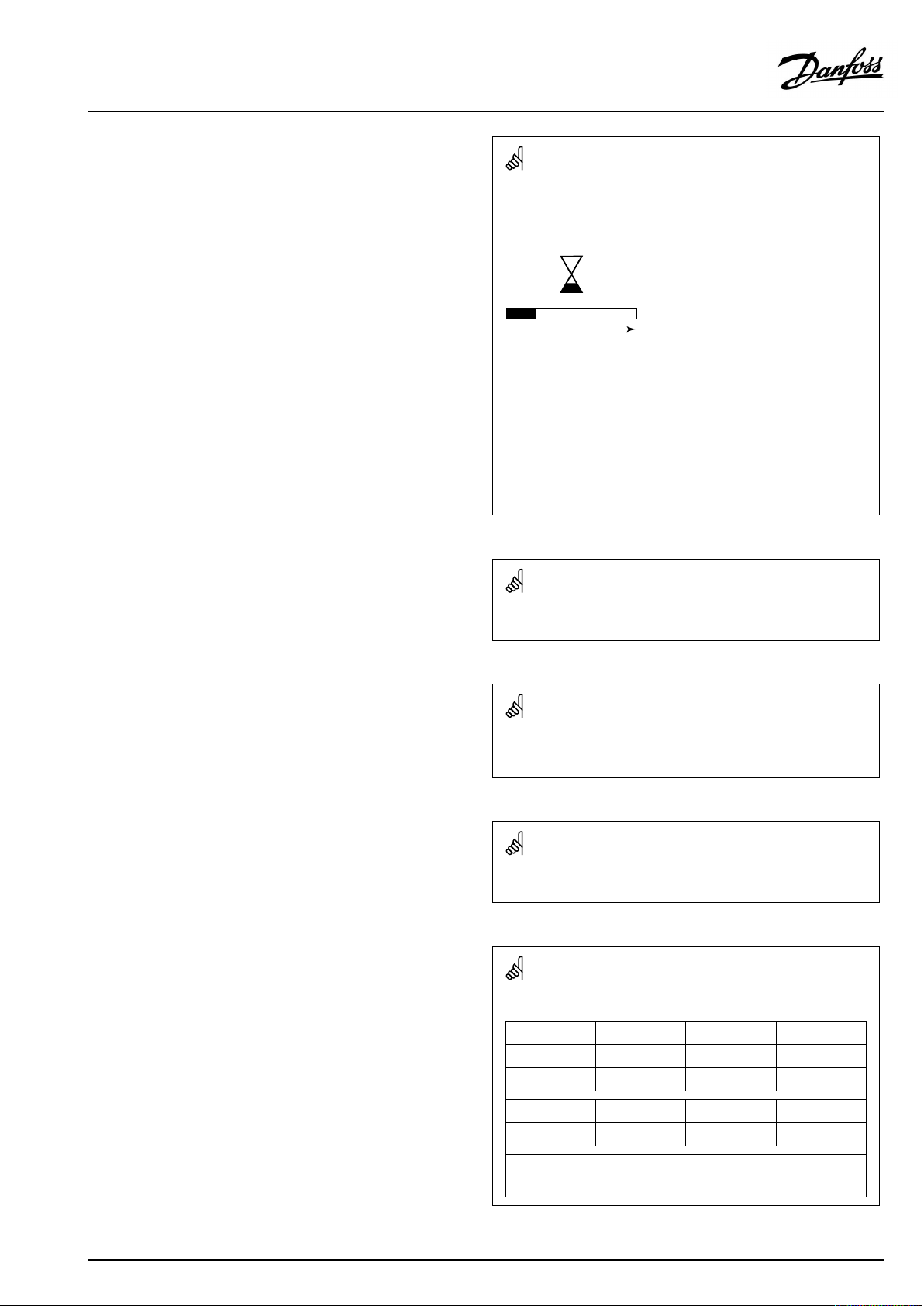
Automaticupdateofcontrollersoftware(firmware):
Thesoftwareofthecontrollerisupdatedautomaticallywhenthekey
isinserted(asofcontrollerversion1.11(ECL210/310)andversion
1.58(ECL296)).Thefollowinganimationwillbeshownwhenthe
softwareisbeingupdated:
Progressbar
Duringupdate:
•DonotremovetheKEY
Ifthekeyisremovedbeforethehour-glassisshown,youhave
tostartafresh.
•Donotdisconnectthepower
Ifthepowerisinterruptedwhenthehour-glassisshown,the
controllerwillnotwork.
•Manualupdateofcontrollersoftware(firmware):
Seethesection"Automatic/manualupdateoffirmware"
Thissymbolindicatesthatthisparticularpieceofinformationshould
bereadwithspecialattention.
AsthisOperatingGuidecoversseveralsystemtypes,specialsystem
settingswillbemarkedwithasystemtype.Allsystemtypesareshown
inthechapter:'Identifyingyoursystemtype'.
°C(degreesCelsius)isameasuredtemperaturevaluewhereasK
(Kelvin)oftenisusedfortemperaturedifferences.
TheIDno.isuniquefortheselectedparameter.
ExampleFirstdigitSeconddigitLastthreedigits
1117411174
-
Circuit1Parameterno.
12174
IfanIDdescriptionismentionedmorethanonce,itmeansthatthere
arespecialsettingsforoneormoresystemtypes.Itwillbemarked
withthesystemtypeinquestion(e.g.12174-A266.9).
1
-
2
Circuit2Parameterno.
AQ120086463710en-010501
174
©Danfoss|2021.06|3
Page 4
OperatingGuideECLComfort310,applicationP330
ParametersindicatedwithanIDno.like"1x607"meanauniversal
parameter.
xstandsforcircuit/parametergroup.
DisposalNote
Thissymbolontheproductindicatesthatitmaynot
bedisposedofashouseholdwaste.
Itmustbehandedovertotheapplicabletake-back
schemefortherecyclingofelectricalandelectronic
equipment.
•Disposeoftheproductthroughchannelsprovided
forthispurpose.
•Complywithalllocalandcurrentlyapplicablelaws
andregulations.
4|©Danfoss|2021.06
AQ120086463710en-010501
Page 5
OperatingGuideECLComfort310,applicationP330
2.0Installation
2.1Beforeyoustart
The14differentapplicationsP330.1...P330.14areheatingand
DHWapplicationsinvariouscombinations.
Thebasicprinciplesforaheatingcircuit
(examplereferringtoP330.1)
Typically,theflowtemperatureisadjustedaccordingtoyour
requirements.
TheflowtemperaturesensorS3isthemostimportantsensor.The
desiredflowtemperatureatS3iscalculatedintheECLcontroller,
basedontheoutdoortemperature(S1)andthedesiredroom
temperature.Thelowertheoutdoortemperature,thehigherthe
desiredflowtemperature.
Bymeansofaweekschedule(upto3'Comfort'periods/day),
theheatingcircuitcanbein'Comfort'or'Saving'mode(two
differenttemperaturevaluesforthedesiredroomtemperature).
ThemotorizedcontrolvalveM1isopenedgraduallywhenthe
flowtemperatureislowerthanthedesiredflowtemperatureand
viceversa.
Thereturntemperature(S5)canbelimited,forexamplenottobe
toohigh.Ifso,thedesiredflowtemperatureatS3canbeadjusted
(typicallytoalowervalue),thusresultinginagradualclosingof
themotorizedcontrolvalve.Furthermore,thereturntemperature
limitationcanbedependentontheoutdoortemperature.
Typically,thelowertheoutdoortemperature,thehigherthe
acceptedreturntemperature.Inboiler-basedheatingsupplythe
returntemperatureshouldnotbetoolow(sameadjustment
procedureasabove).
Aflow/powerlimitationcanbearrangedbyusinganM-busbased
signalfromaflow/heatmeter.Furthermore,thelimitationcanbe
inrelationtotheoutdoortemperature.
Ifthemeasuredroomtemperature,S13orviatheremotecontrol
unitECA30doesnotequalthedesiredroomtemperature,the
desiredflowtemperaturecanbeadjusted.
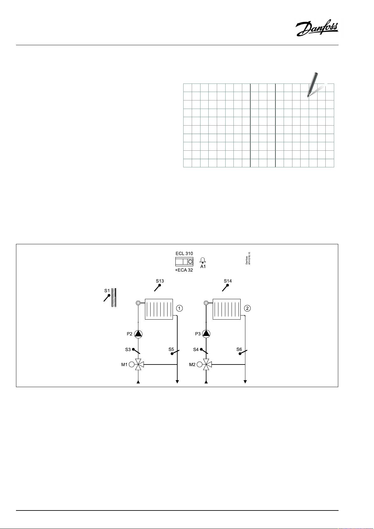
ApplicationP330.1:
Theshowndiagramisafundamentalandsimplifiedexampleanddoes
notcontainallcomponentsthatarenecessaryinasystem.
AllnamedcomponentsareconnectedtotheECLComfortcontroller.
Listofcomponents,forexampleheatingcircuit1(P330.1):
S1
Outdoortemperaturesensor
S3
Flowtemperaturesensor
S5
(Optional)Returntemperaturesensor
S8
(Optional)Externaltemperaturecontrol,notillustrated
S13
(Optional)Roomtemperaturesensor
M1
Motorizedcontrolvalve
P2
Circulationpump
A1
Alarm
Generalinformation:
In’Saving’modetheheatingcanbereducedortotallyswitched
off.The‘Frostprotection’modemaintainsaselectableflow
temperature,forexample10°C.
Thecirculationpump(P2)isONatheatdemandoratfrost
protection.
TheheatingcanbeswitchedOFFwhentheoutdoortemperatureis
higherthanaselectablevalue.
Thedesiredflowtemperatureofheatingcircuit1can,viaS8,be
controlledbymeansofanexternalvoltageintherange0-10volt.
Exerciseofcirculationpumpandcontrolvalvecanbearranged.
AQ120086463710en-010501
©Danfoss|2021.06|5
Page 6
OperatingGuideECLComfort310,applicationP330
ThebasicprinciplesforaDHWcircuit,type1
(examplereferringtoP330.4)
Bymeansofaweekschedule(upto3'Comfort'periods/day),the
DHWcircuitcanbein'Comfort'or'Saving'mode(twodifferent
temperaturevaluesforthedesiredDHWtemperatureatS10).
TheDHWheatingtemperaturesensorS9isthemostimportant
sensor.IfthemeasuredDHWtemperature(S10)getslowerthanthe
desiredDHWtemperature,theDHWheatingpump(P7)isswitched
ON.Themotorizedcontrolvalve(M3)iscontrolledinorderto
maintaintheDHWheatingtemperatureatS9.TheDHWheating
temperatureisdeterminedbythedesiredDHWtemperatureatS10
plusthechargingdifference.WhentheDHWheatingtemperature
isreached,theDHWchargingpumpP5isswitchedON.TheDHW
heatingtemperatureatS9istypically5–10degreeshigherthan
thedesiredDHWtemperature.
DHWtankwith1temperaturesensor(S10):
WhenthemeasuredDHWtemperature(S10)getshigherthanthe
desiredDHWtemperature,theDHWheatingpump(P7)andthe
DHWchargingpump(P5)areswitchedOFF.Thepost-runtimecan
besetindividually.
DHWtankwith2temperaturesensors(S10,upperandS2,
lower):
IfthemeasuredDHWtemperature(S10)getshigherthanthe
desiredDHWtemperatureandthetemperature(atS2)getshigher
thanthecut-outtemperature,theDHWheatingpump(P7)and
theDHWchargingpump(P5)areswitchedOFF.Thepost-runtime
canbesetindividually.
TheDHWcirculationcanbethroughtheDHWtank(connectionA)
orthroughtheheat-exchanger(connectionB).Thesolutionwith
connectionAresultsinclosingofthemotorizedcontrolvalveafter
theDHWtankchargingprocedure.Thesolutionwithconnection
BisusedtocompensatefortheheatlossintheDHWcirculation
pipe.Furthermore,afterDHWtankcharging,theDHWheating
temperature(atS9)iscontrolledaccordingtothedesiredDHW
temperature.
Thereturntemperature(S7)canbelimited,forexamplenottobe
toohigh.Ifso,thedesiredflowtemperatureatS9canbeadjusted
(typicallytoalowervalue),thusresultinginagradualclosingofthe
motorizedcontrolvalve.Inboiler-basedheatingsupplythereturn
temperatureshouldnotbetoolow(sameadjustmentprocedure
asabove).
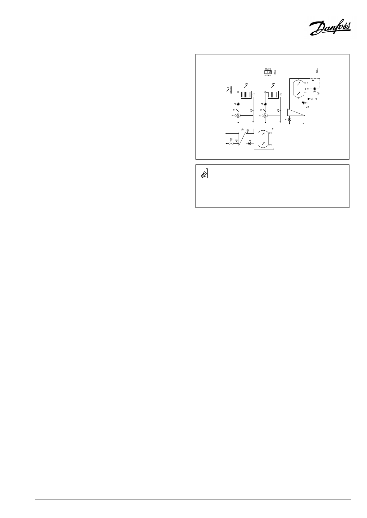
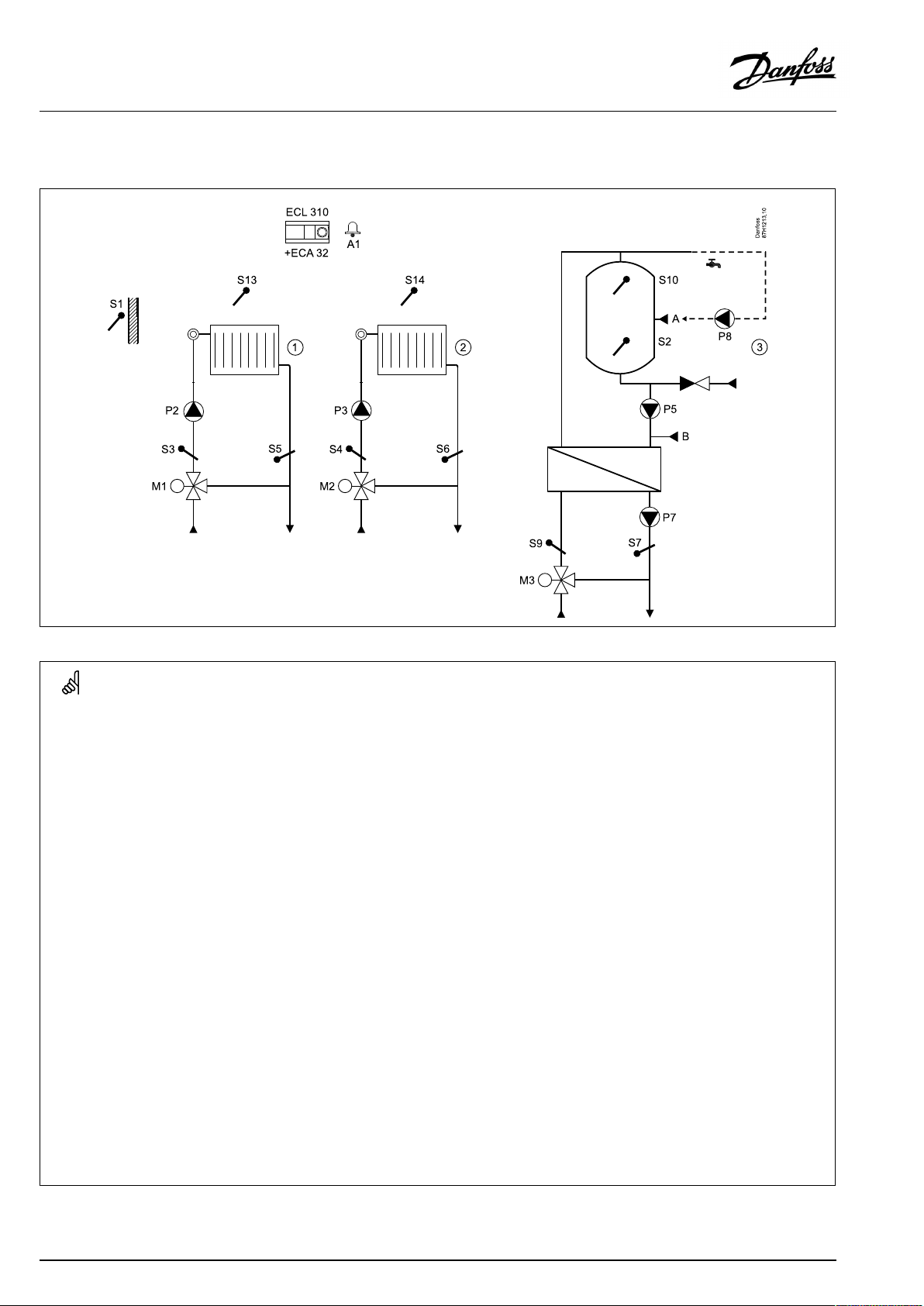
ApplicationP330.4:
Theshowndiagramisafundamentalandsimplifiedexampleanddoes
notcontainallcomponentsthatarenecessaryinasystem.
AllnamedcomponentsareconnectedtotheECLComfortcontroller.
Listofcomponents,forexampleDHWcircuit,type1(P330.4):
S1
Outdoortemperaturesensor
S2
(Optional)LowerDHWtanktemperaturesensor
S7
(Optional)Returntemperaturesensor
S9
Flowtemperaturesensor
S10
UpperDHWtanktemperaturesensorr
M3
Motorizedcontrolvalve
P5
DHWchargingpump
P7
DHWheatingpump
P8
DHWcirculationpump
A1
Alarm
Aflow/powerlimitationcanbearrangedbyusinganM-busbased
signalfromaflow/heatmeter.
Generalinformation:
The‘Frostprotection’modemaintainsaselectabletemperature,
forexample10°C.
Ananti-bacteriafunctionisavailableforactivationonselected
daysoftheweek.
TheoutdoortemperaturesensorS1isusedtoprotectthe
circulationcircuitagainstfrost.
TheDHWcirculationpump(P8)hasaweekscheduleforupto3
ONperiodsperday.
6|©Danfoss|2021.06
AQ120086463710en-010501
Page 7
OperatingGuideECLComfort310,applicationP330
ThebasicprinciplesforaDHWcircuit,type2
(examplereferringtoP330.5)
Bymeansofaweekschedule(upto3'Comfort'periods/day),the
DHWcircuitcanbein'Comfort'or'Saving'mode(twodifferent
temperaturevaluesforthedesiredDHWtemperatureatS10).
WhenthemeasuredDHWtemperature(S10)getslowerthanthe
desiredDHWtemperature,theDHWheatingpump(P7)andthe
DHWchargingpump(P5)areswitchedON.
DHWtankwith1temperaturesensor(S10):
WhenthemeasuredDHWtemperature(S10)getshigherthanthe
desiredDHWtemperature,theDHWheatingpump(P7)andthe
DHWchargingpump(P5)areswitchedOFF.Thepost-runtimecan
besetindividually.
DHWtankwith2temperaturesensors(S10,upperandS2,
lower):
WhenthemeasuredDHWtemperature(S10)getshigherthanthe
desiredDHWtemperatureandthetemperature(atS2)getshigher
thanthecut-outtemperature,theDHWheatingpump(P7)and
theDHWchargingpump(P5)areswitchedOFF.Thepost-runtime
canbesetindividually.
TheDHWcirculationcanbethroughtheDHWtank(connectionA)
orthroughtheheat-exchanger(connectionB).Thesolutionwith
connectionAresultsinclosingofthemotorizedcontrolvalveafter
theDHWtankchargingprocedure.Thesolutionwithconnection
BisusedtocompensatefortheheatlossintheDHWcirculation
pipe.AfterDHWtankcharging,theDHWchargingpumpP5stops.
TheheatingpumpP7continuesbeingswitchedON.
Ananti-bacteriafunctionisavailableforactivationonselected
daysoftheweek.
ApplicationP330.5:
Theshowndiagramisafundamentalandsimplifiedexampleanddoes
notcontainallcomponentsthatarenecessaryinasystem.
AllnamedcomponentsareconnectedtotheECLComfortcontroller.
Listofcomponents,forexampleDHWcircuit,type2(P330.5):
S1
Outdoortemperaturesensor
S2
(Optional)LowerDHWtanktemperaturesensor
S10
UpperDHWtanktemperaturesensor
P5
DHWchargingpump
P7
DHWheatingpump
P8
DHWcirculationpump
A1
Alarm
TheoutdoortemperaturesensorS1isusedtoprotectthe
circulationcircuitagainstfrost.
TheDHWcirculationpump(P8)hasaweekscheduleforupto3
ONperiodsperday.
Generalinformation:
The‘Frostprotection’modemaintainsaselectabletemperature,
forexample10°C.
AQ120086463710en-010501
©Danfoss|2021.06|7
Page 8
OperatingGuideECLComfort310,applicationP330
Thebasicprinciplesforthemastercircuit
(examplereferringtoP330.10)
ThedesiredflowtemperatureatS3isadjustedaccordingtothe
demandfromthesub-circuits(heatingandDHWcircuits).Theflow
temperaturesensorS3isthemostimportantsensor.
ThemotorizedcontrolvalveM1isopenedgraduallywhenthe
flowtemperatureislowerthanthedesiredflowtemperatureand
viceversa.
Thereturntemperature(S5)canbelimited,forexamplenottobe
toohigh.Ifso,thedesiredflowtemperatureatS3canbeadjusted
(typicallytoalowervalue),thusresultinginagradualclosingof
themotorizedcontrolvalve.Furthermore,thereturntemperature
limitationcanbedependentontheoutdoortemperature.
Typically,thelowertheoutdoortemperature,thehigherthe
acceptedreturntemperature.
Inboiler-basedheatingsupplythereturntemperatureshouldnot
betoolow(sameadjustmentprocedureasabove).
Thecirculationpump(P1)isONatheatdemandoratfrost
protection.
Generalinformation:
Thedesiredflowtemperatureofthemastercircuitcan,viaS8,be
controlledbymeansofanexternalvoltageintherange0-10volt.
ApplicationP330.10:
Theshowndiagramisafundamentalandsimplifiedexampleanddoes
notcontainallcomponentsthatarenecessaryinasystem.
AllnamedcomponentsareconnectedtotheECLComfortcontroller.
Listofcomponents,forexamplemastercircuit(P330.10):
S1
Outdoortemperaturesensor
S3
Flowtemperaturesensor
S5
(Optional)Returntemperaturesensor
S8
(Optional)Externaltemperaturecontrol,notillustrated
M1
Motorizedcontrolvalve
P1
Circulationpump
A1
Alarm
8|©Danfoss|2021.06
AQ120086463710en-010501
Page 9
OperatingGuideECLComfort310,applicationP330
Thebasicprinciplesforthemastercircuitwithbuffer
(examplereferringtoP330.14)
Thehighestdemandfromthesub-circuits(heatingandDHW
circuits)plusadifference('Demandoffset')determinethedesired
buffertanktemperatureatS11.
Whenthemeasuredbuffertanktemperature(S11)getslowerthan
thedesiredbuffertanktemperature,thechargingpump(P1)is
switchedON.
Themotorizedcontrolvalve(M1)iscontrolledinordertomaintain
thebuffertankheatingtemperatureatS3.Themotorizedcontrol
valveisopenedgraduallywhentheflowtemperatureislowerthan
thedesiredflowtemperatureandviceversa.
TheflowtemperaturesensorS3isthemostimportantsensor.
ThedesiredtemperatureatS3isdeterminedbythedesiredbuffer
tanktemperatureatS11plusachargingtemperaturedifference.
ThebuffertankheatingtemperatureatS3istypically5–10degrees
higherthanthedesiredbuffertanktemperature.
Buffertankwith1temperaturesensor(S11):
Whenthemeasuredbuffertanktemperature(S11)getshigher
thanthedesiredbuffertanktemperature,thechargingpump(P1)
isswitchedOFF.Thepost-runtimecanbeset.
Buffertankwith2temperaturesensors(S11,upperandS12,
lower):
Whenthemeasuredupperbuffertanktemperature(S11)gets
higherthanthedesiredbuffertanktemperatureandthemeasured
lowerbuffertanktemperature(S12)getshigherthanthecut-out
temperature,thechargingpump(P1)isswitchedOFF.Thepost-run
timecanbeset.
IfS12isnotconnected,S11willbeusedforONandOFFcontrolof
thechargingpump.
Thereturntemperature(S5)canbelimited,forexamplenottobe
toohigh.Ifso,thedesiredflowtemperatureatS3canbeadjusted
(typicallytoalowervalue),thusresultinginagradualclosingof
themotorizedcontrolvalve.Furthermore,thereturntemperature
limitationcanbedependentontheoutdoortemperature.
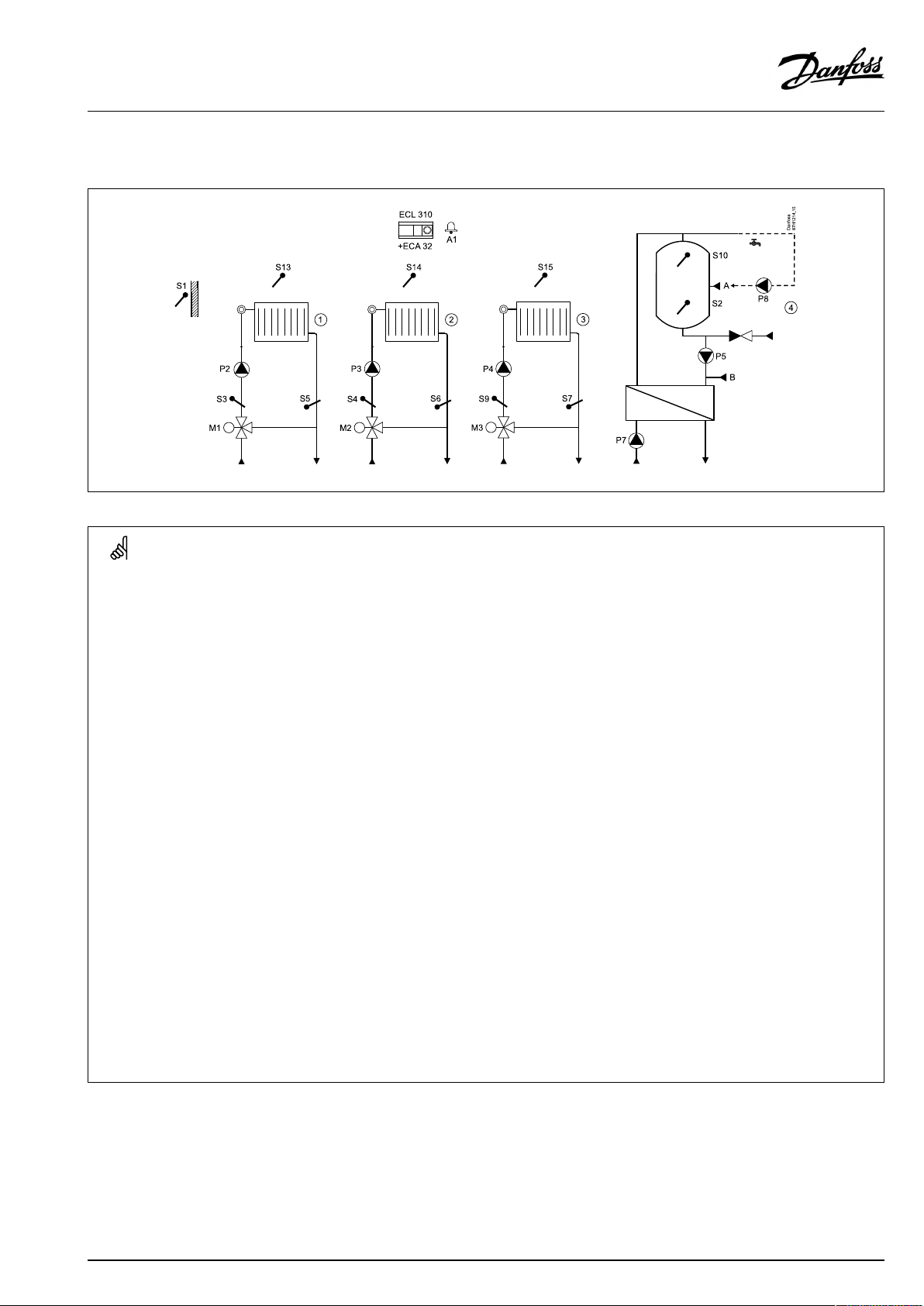
ApplicationP330.14:
Theshowndiagramisafundamentalandsimplifiedexampleanddoes
notcontainallcomponentsthatarenecessaryinasystem.
AllnamedcomponentsareconnectedtotheECLComfortcontroller.
Listofcomponents,forexamplemastercircuitwithbuffer(P330.14):
S1
Outdoortemperaturesensor
S3
Flowtemperaturesensor
S5
(Optional)Returntemperaturesensor
S8
(Optional)Externaltemperaturecontrol,notillustrated
S11
Upperbuffertanktemperaturesensor
S12
(Optional)Lowerbuffertanktemperaturesensor
M1
Motorizedcontrolvalve
P1
Buffertankchargingpump
A1
Alarm
Typically,thelowertheoutdoortemperature,thehigherthe
acceptedreturntemperature.
Inboiler-basedheatingsupplythereturntemperatureshouldnot
betoolow(sameadjustmentprocedureasabove).
Whenthemeasuredbuffertemperature(S11)getshigherthan
thedesiredbuffertemperature,thedesiredtemperatureatS3is
loweredtotypically10°C.Hereafterthechargingpump(P1)is
switchedOFF.Thepost-runtimecanbeset.
AQ120086463710en-010501
©Danfoss|2021.06|9
Page 10

OperatingGuideECLComfort310,applicationP330
ApplicationP330.14:
InordertoavoidadischargingoftheDHWcircuit(ahigher
DHWtemperaturegoestoalowerbuffertanktemperature)two
parameterscanbeset:
*
Theparameter("Tankstartdiff.",IDno13192)determinesan
acceptabletemperaturedifferencebetweenS10andS11in
ordertostarttheDHWcharging.
*
Theparameter("Tankstopdiff." ,IDno13196)determinesan
acceptabletemperaturedropofthedifferencebetweenS10
andS11inordertostoptheDHWcharging.
Generalinformation:
Thedesiredflowtemperatureofthemastercircuitcan,viaS8,be
controlledbymeansofanexternalvoltageintherange0-10volt.
10|©Danfoss|2021.06
AQ120086463710en-010501
Page 11

OperatingGuideECLComfort310,applicationP330
ApplicationP330.1–P330.5:
Heatingcircuits2,3,4andDHWcircuitscanbeconnectedafter
heatingcircuit1.Circuit1actsasmasterandcanreactonthe
sub-circuitsdemand.Ifso,thedesiredflowtemperatureatS3can
beinfluencedbythedesiredflowtemperatureatS4,S9,S10and
DHWchargingtemperaturerespectively.
Thedesiredflowtemperatureofheatingcircuit1can,viaS8,be
controlledbymeansofanexternalvoltageintherange0-10volt.
ApplicationP330.6–P330.15:
HeatingcircuitsandDHWcircuitsaretypicallyconnected
afterthemastercontrolledcircuit(M).Whenso,thedesired
flowtemperatureatS3canbeinfluencedbythedesiredflow
temperatureatS4,S9,S10andDHWchargingtemperatures.
Thedesiredflowtemperatureofthemastercircuitcan,viaS8,be
controlledbymeansofanexternalvoltageintherange0-10volt.
ApplicationP330ingeneral:
UptotwoRemoteControlUnits,theECA30(oneforeachheating
circuit)canbeconnectedtooneECLcontrollerinordertomeasure
theroomtemperatureandcontroltheECLcontrollerremotely.
WhentheDHWcircuitisactiveduringthechargingprocedure,
selectedheatingcircuitscanbeclosedinordertogivehigher
prioritytotheDHWcharging.
Oneormoreconnectedfloworenergymeters(basedonM-bus
signal)canlimitthefloworenergytoasetmaximum(DHW
circuits)andinrelationtotheoutdoortemperature(heatingand
mastercircuits).
Unusedinputcan,bymeansofanoverrideswitch,beusedto
overridethescheduletoafixed'Comfort'or'Saving'mode.
InputS8canbeusedtocontrolthedesiredflowtemperatureof
heatingcircuit1orthemastercircuit.Theappliedvoltagesignalin
therange0-10voltisconvertedintheECLcontrollertothedesired
flowtemperature.
ModbuscommunicationtoaSCADAsystemcanbeestablished.
TheM-busdatacanfurthermorebetransferredtotheModbus
communication.
Alarmrelay(R6)canbeactivated:
•iftheactualflowtemperaturediffersfromthedesiredflow
temperature.
•ifatemperaturesensororitsconnectiondisconnects/short
circuits.(See:Commoncontrollersettings>System>Raw
inputoverview).
Thecontrollerispre-programmedwithfactorysettingsthatareshown
inthe‘ParameterIDoverview’appendix.
AQ120086463710en-010501
©Danfoss|2021.06|11
Page 12
OperatingGuideECLComfort310,applicationP330
2.2Identifyingthesystemtype
Sketchyourapplication
TheECLComfortcontrollerseriesisdesignedforawiderange
ofheating,domestichot-water(DHW)andcoolingsystemswith
differentconfigurationsandcapacities.Ifyoursystemdiffers
fromthediagramsshownhere,youmaywanttomakeasketch
ofthesystemabouttobeinstalled.Thismakesiteasiertouse
theOperatingGuide,whichwillguideyoustep-by-stepfrom
installationtofinaladjustmentsbeforetheend-usertakesover.
TheECLComfortcontrollerisauniversalcontrollerthatcanbe
usedforvarioussystems.Basedontheshownstandardsystems,
itispossibletoconfigureadditionalsystems.Inthischapteryou
findthemostfrequentlyusedsystems.Ifyoursystemisnotquite
asshownbelow,findthediagramwhichhasthebestresemblance
withyoursystemandmakeyourowncombinations.
SeetheInstallationGuide(deliveredwiththeapplicationkey)for
applicationtypes/sub-types.
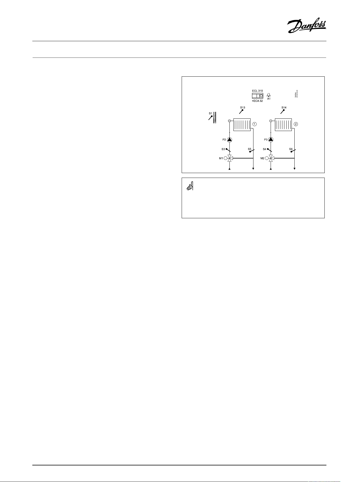
P330.1
Twoheatingcircuits
12|©Danfoss|2021.06
AQ120086463710en-010501
Page 13

OperatingGuideECLComfort310,applicationP330
SpecialsettingsfortypeP330.1:
Navigation:
Heatingcircuit(circuit2)
Heatingcircuit2canbeasub-circuittoheatingcircuit1.
Settingsforsub-circuitinordertosenddemandtocircuit1:
MENU\Settings\Application:‘SenddesiredT’
Heatingcircuit(circuit1)
Settingsforcircuit1inordertoreactondemandinsub-circuit:
MENU\Settings\Application:'Demandoffset'
*Thisvalueisaddedtotheheatdemandvaluefromsub-circuit
IDno.:
1x500
11017
Recommendedsetting:
ON
3K*
AQ120086463710en-010501
©Danfoss|2021.06|13
Page 14
OperatingGuideECLComfort310,applicationP330
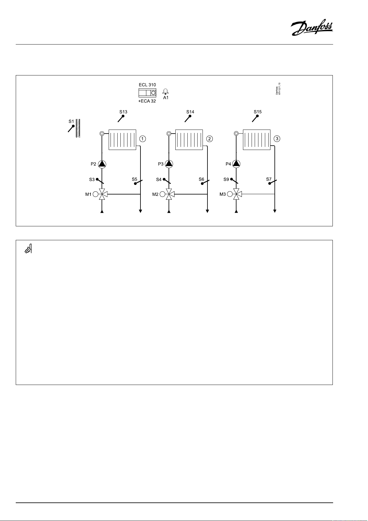
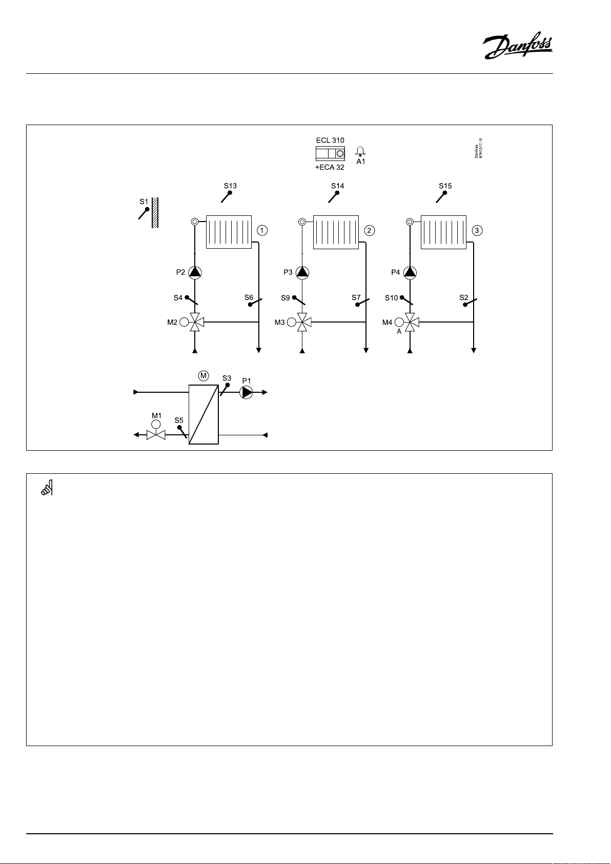
P330.2
Threeheatingcircuits
SpecialsettingsfortypeP330.2:
Navigation:
Heatingcircuit(circuit2and3)
Heatingcircuit2and3canbesub-circuitstoheatingcircuit1.
Settingsforsub-circuit(s)inordertosenddemandtocircuit1:
MENU\Settings\Application:'SenddesiredT'
Heatingcircuit(circuit1)
Settingsforcircuit1inordertoreactondemandinsub-circuit(s):
MENU\Settings\Application:'Demandoffset'
*Thisvalueisaddedtotheheatdemandvaluefromsub-circuit(s)
IDno.:
1x500
11017
Recommendedsetting:
ON
3K*
14|©Danfoss|2021.06
AQ120086463710en-010501
Page 15
OperatingGuideECLComfort310,applicationP330
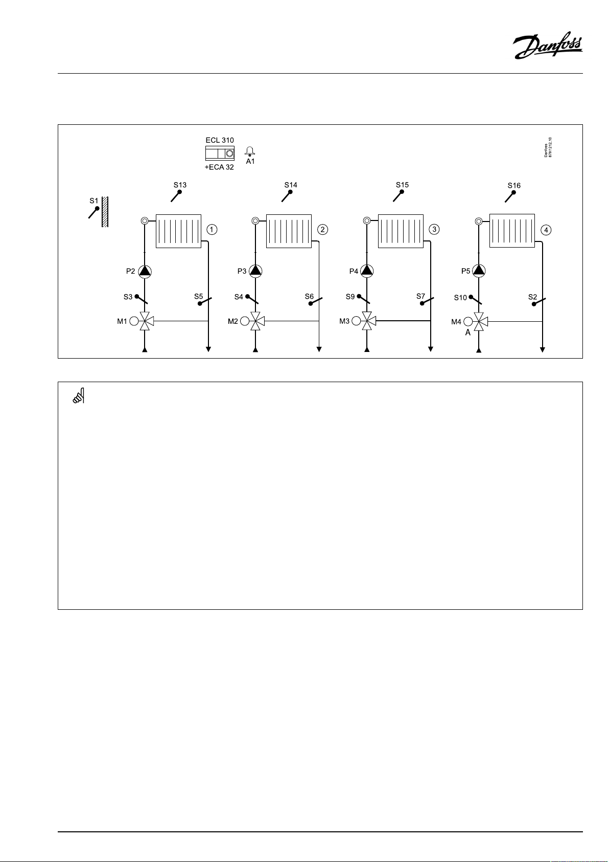
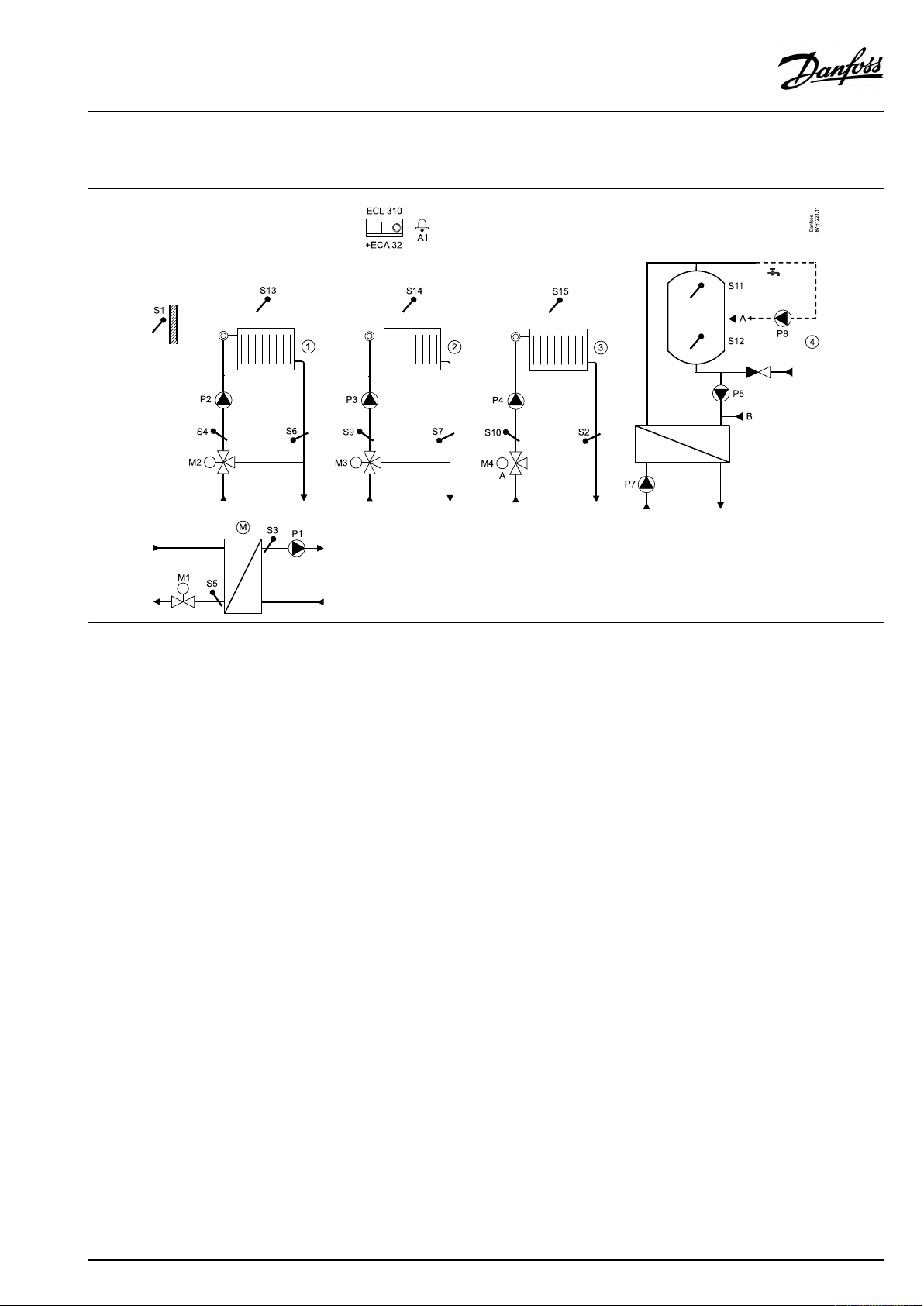
P330.3
Fourheatingcircuits.TheMCVincircuit4iscontrolledby0–10V.
SpecialsettingsfortypeP330.3
Navigation:
Heatingcircuit(circuit2,3and4)
Heatingcircuit2,3and4canbesub-circuitstoheatingcircuit1.
Settingsforsub-circuit(s)inordertosenddemandtocircuit1:
MENU\Settings\Application:'SenddesiredT'
Heatingcircuit(circuit1)
Settingsforcircuit1inordertoreactondemandinsub-circuit(s):
MENU\Settings\Application:'Demandoffset'
*Thisvalueisaddedtotheheatdemandvaluefromsub-circuit(s)
IDno.:
1x500
11017
Recommendedsetting:
ON
3K*
AQ120086463710en-010501
©Danfoss|2021.06|15
Page 16
OperatingGuideECLComfort310,applicationP330
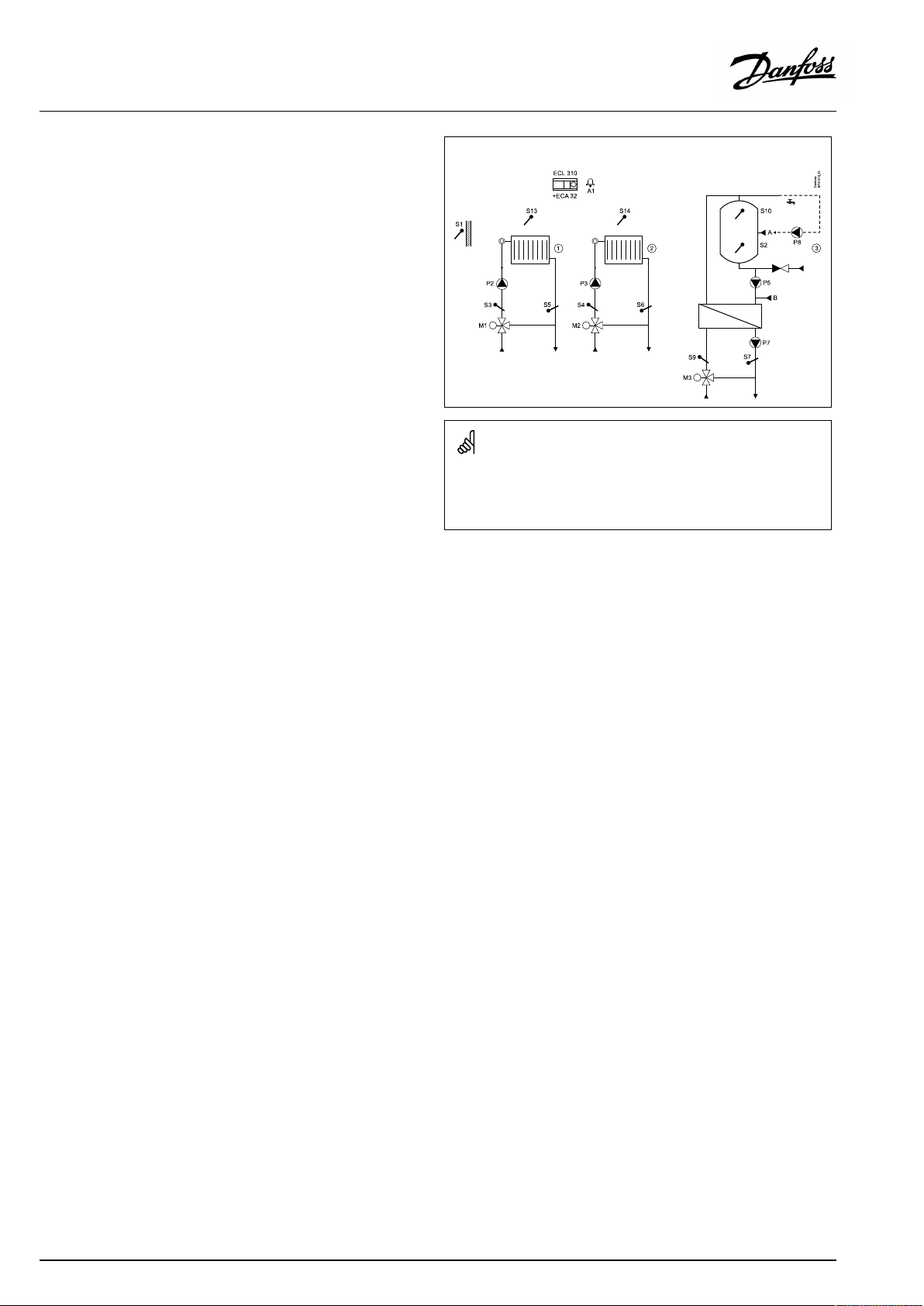
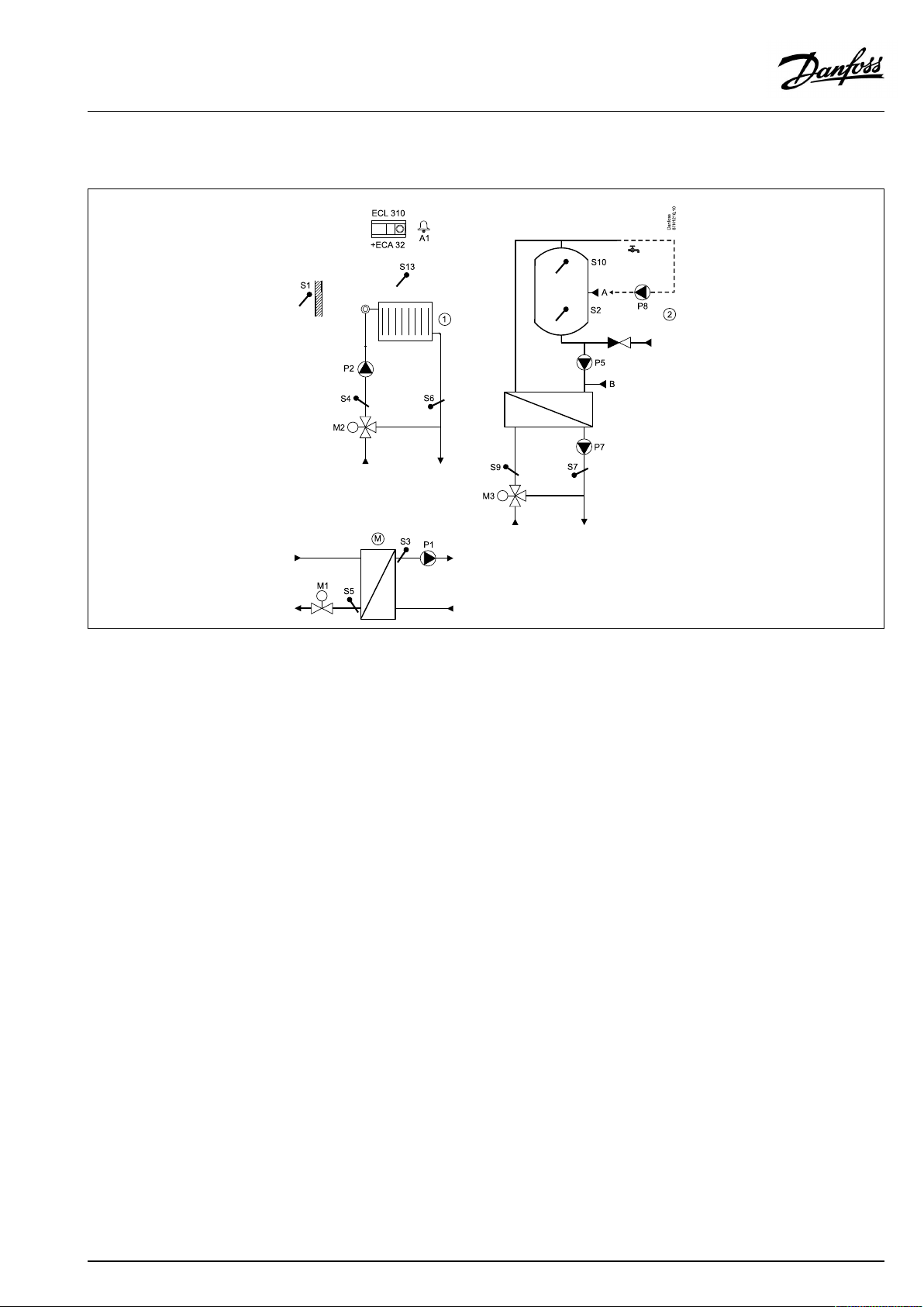
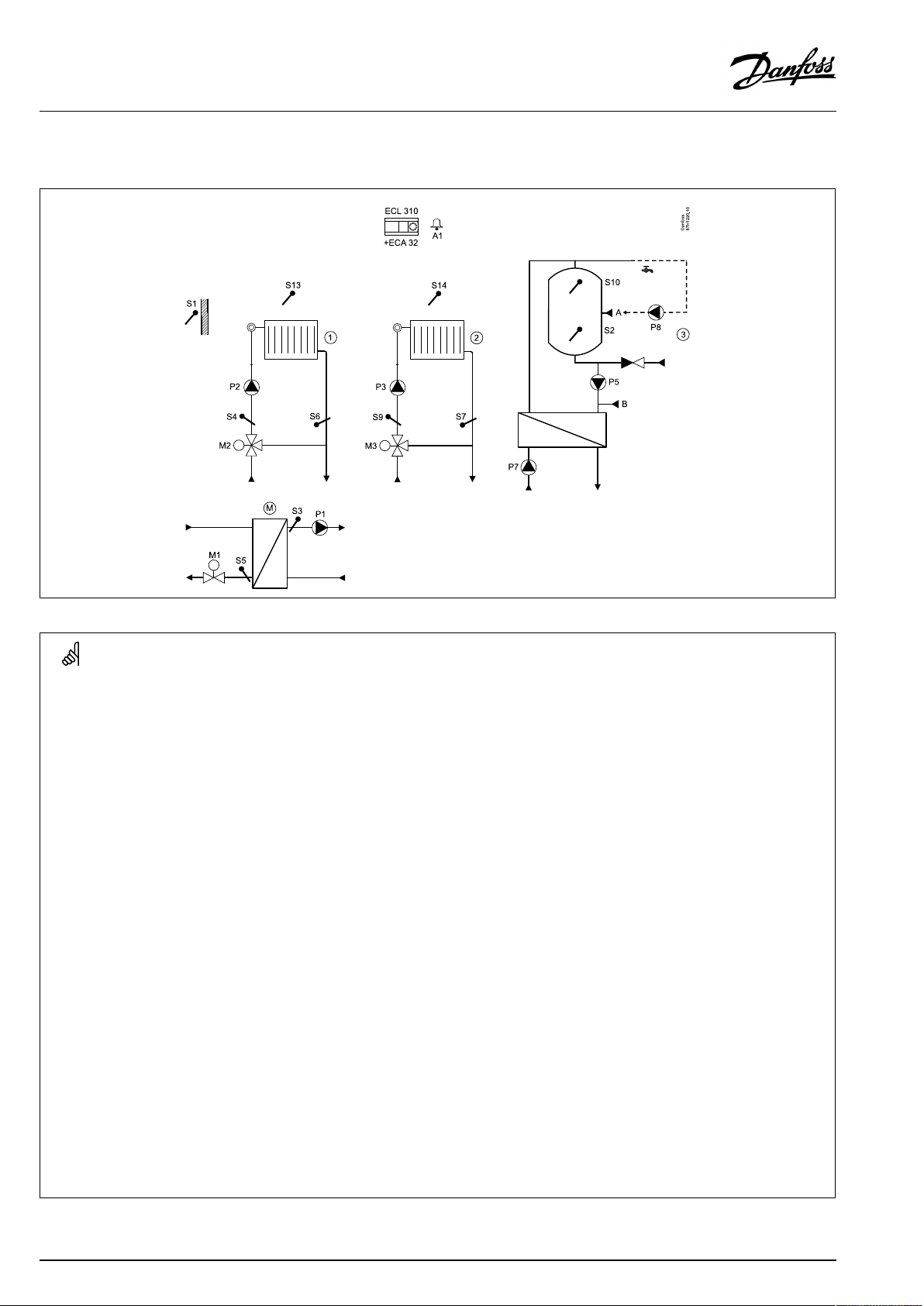
P330.4
TwoheatingcircuitsandoneDHWchargingcircuitwithcontrolledheatingtemperature.
SpecialsettingsfortypeP330.4:
Navigation:
Heatingcircuit2andDHWcircuit
Heatingcircuit2andtheDHWcircuitcanbesub-circuitstoheatingcircuit1.
Settingsforsub-circuit(s)inordertosenddemandtocircuit1:
MENU\Settings\Application:'SenddesiredT'
Heatingcircuit(circuit1)
Settingsforcircuit1inordertoreactondemandinsub-circuit(s):
MENU\Settings\Application:'Demandoffset'
*Thisvalueisaddedtotheheatdemandvaluefromsub-circuit(s)
DHWcirculationpipe
TheDHWcirculationpipecanbeconnectedtotheDHWtankat'A'forinternal
circulationortotheheatexchangerat'B'forexternalcirculation.
(InternalDHWcirculation)MENU\Settings\Application:'Cont.Tcontrol'1x054OFF
(ExternalDHWcirculation)MENU\Settings\Application:'Cont.Tcontrol'1x054ON
IDno.:
1x500
11017
Recommendedsetting:
ON
3K*
16|©Danfoss|2021.06
AQ120086463710en-010501
Page 17
OperatingGuideECLComfort310,applicationP330
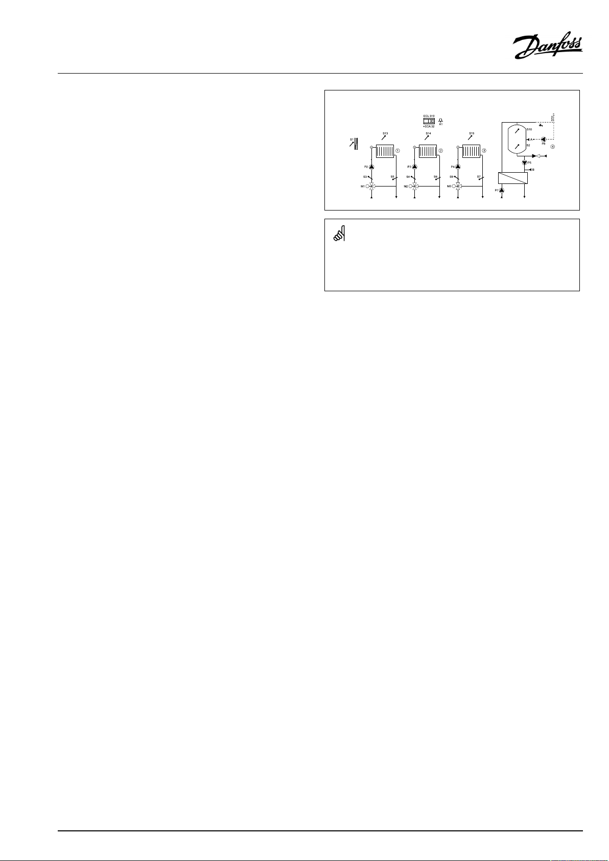
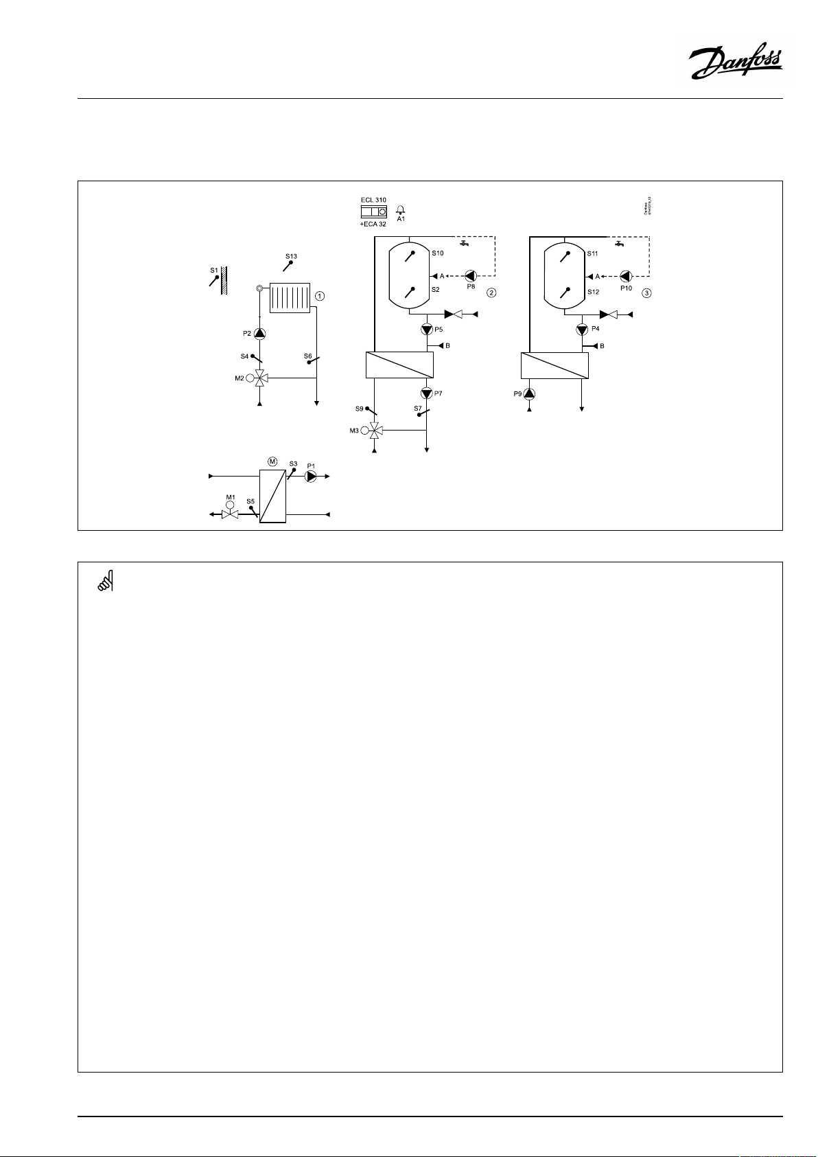
P330.5
ThreeheatingcircuitsandoneDHWchargingcircuit.
SpecialsettingsfortypeP330.5
Navigation:
Heatingcircuit2and3andDHWcircuit
Heatingcircuit2and3andtheDHWcircuitcanbesub-circuitstoheatingcircuit1.
Settingsforsub-circuit(s)inordertosenddemandtocircuit1:
MENU\Settings\Application:'SenddesiredT'
Heatingcircuit(circuit1)
Settingsforcircuit1inordertoreactondemandinsub-circuit(s):
MENU\Settings\Application:'Demandoffset'
*Thisvalueisaddedtotheheatdemandvaluefromsub-circuit(s)
DHWcirculationpipe
TheDHWcirculationpipecanbeconnectedtotheDHWtankat'A'forinternal
circulationortotheheatexchangerat'B'forexternalcirculation.
(InternalDHWcirculation)MENU\Settings\Application:'Cont.Tcontrol'
IDno.:
1x500
11017
1x054
Recommendedsetting:
ON
3K*
OFF
(ExternalDHWcirculation)MENU\Settings\Application:'Cont.Tcontrol'
AQ120086463710en-010501
1x054
ON
©Danfoss|2021.06|17
Page 18
OperatingGuideECLComfort310,applicationP330
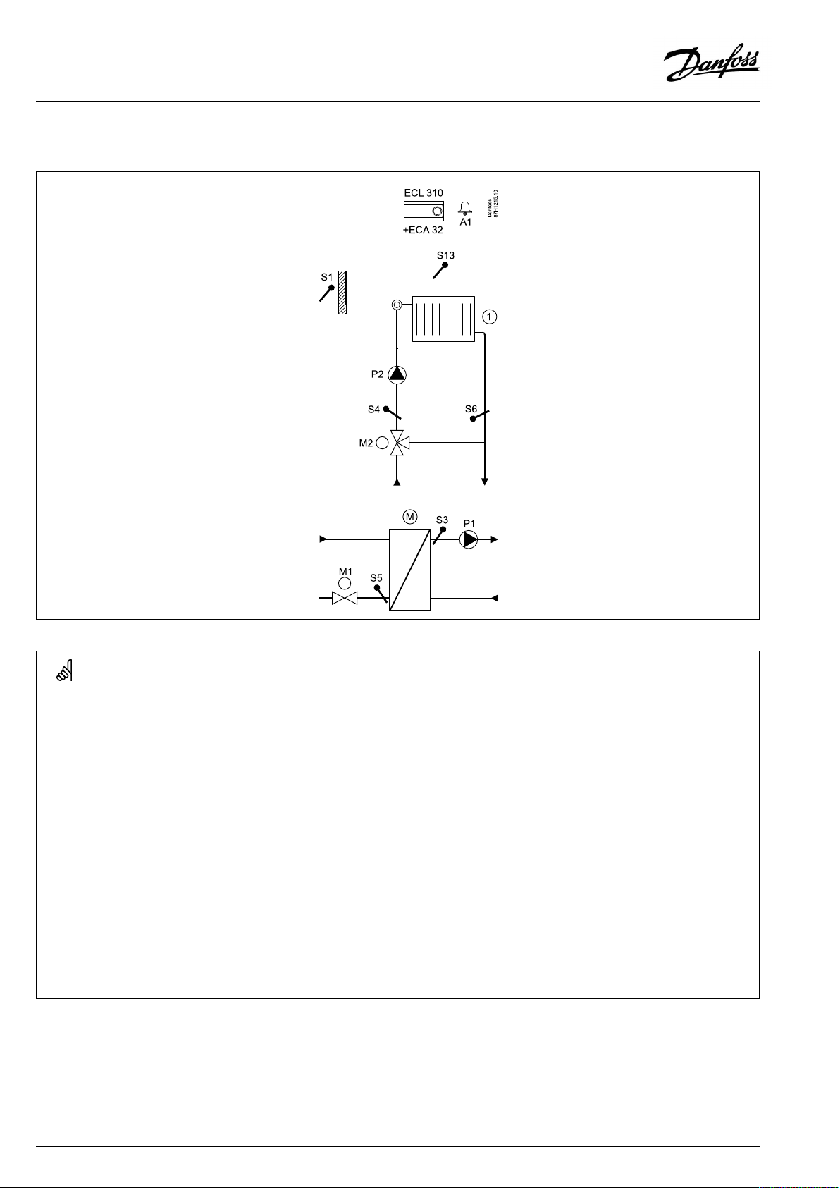
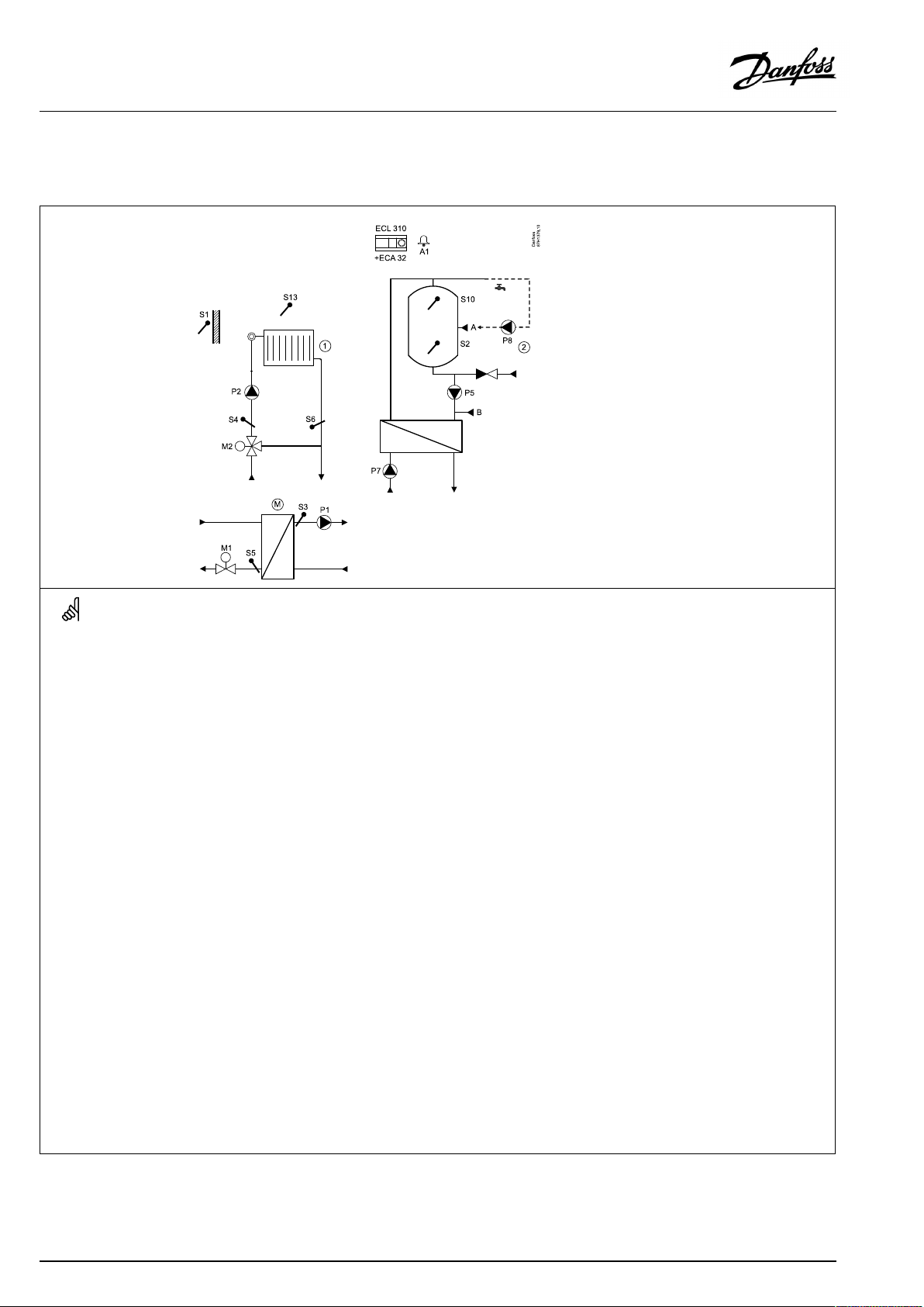
P330.6
Onemastercircuitandoneheatingcircuitassub-circuit.
SpecialsettingsfortypeP330.6:
Navigation:
Themastercircuitreactsondemandinthesub-circuit.
Sub-circuit
Settingsforsub-circuitinordertosenddemandtomastercircuit:
MENU\Settings\Application:'SenddesiredT'
Mastercircuit
Settingsformastercircuitinordertoreactondemandinsub-circuit:
MENU\Settings(M)\Application:'Demandoffset'
*Thisvalueisaddedtotheheatdemandvaluefromsub-circuit
IDno.:
1x500
1x017
Recommendedsetting:
ON
3K*
18|©Danfoss|2021.06
AQ120086463710en-010501
Page 19
OperatingGuideECLComfort310,applicationP330
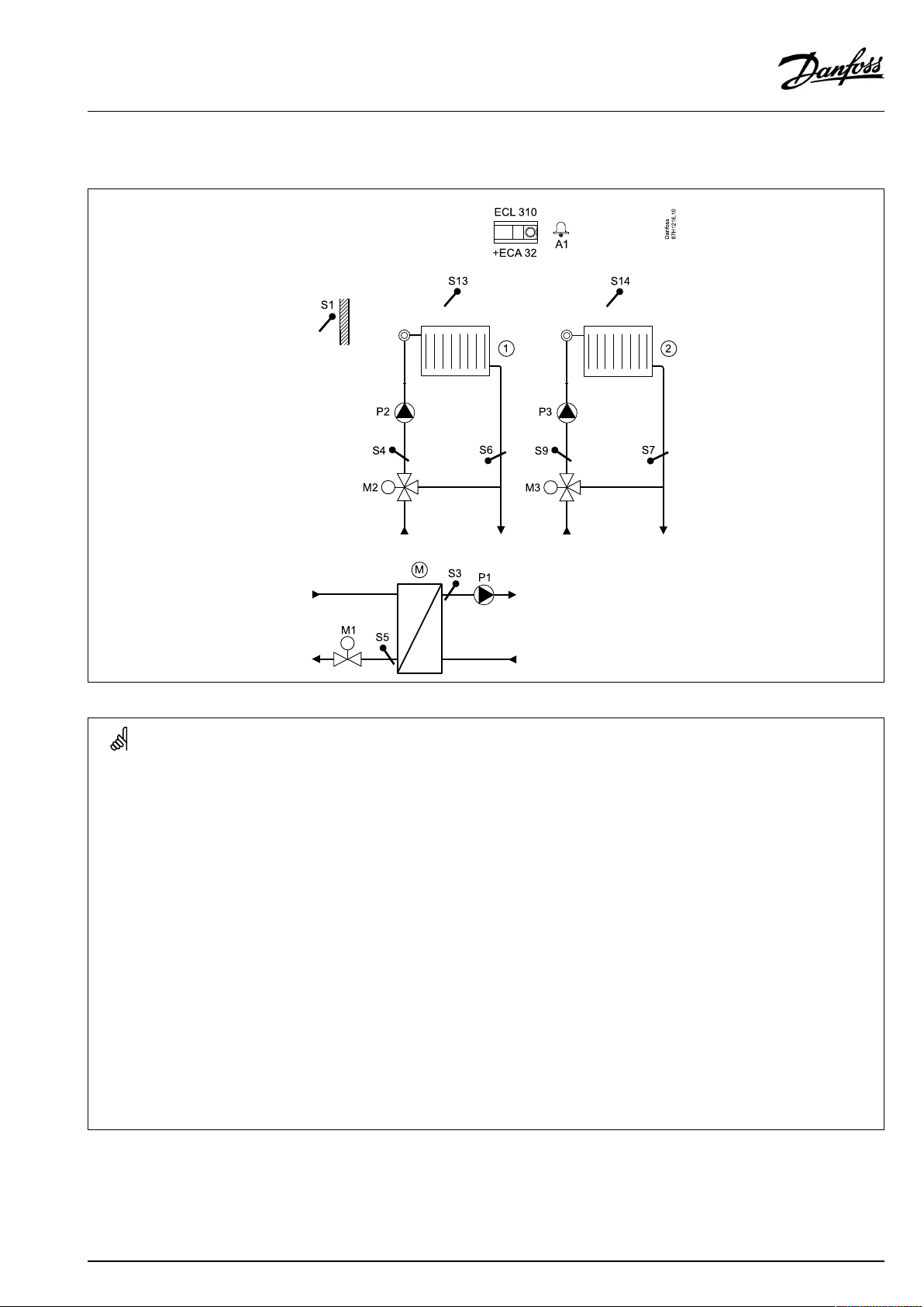
P330.7
Onemastercircuitandtwoheatingcircuitsassub-circuits.
SpecialsettingsfortypeP330.7
Navigation:
Themastercircuitreactsondemandinthesub-circuit(s).
Sub-circuit(s)
Settingsforsub-circuit(s)inordertosenddemandtomastercircuit:
MENU\Settings\Application:'SenddesiredT'
Mastercircuit
Settingsformastercircuitinordertoreactondemandinsub-circuit(s):
MENU\Settings(M)\Application:'Demandoffset'
*Thisvalueisaddedtotheheatdemandvaluefromsub-circuit(s)
IDno.:
1x500
1x017
Recommendedsetting:
ON
3K*
AQ120086463710en-010501
©Danfoss|2021.06|19
Page 20
OperatingGuideECLComfort310,applicationP330
P330.8
Onemastercircuitandthreeheatingcircuitsassub-circuits.TheMCVincircuit3iscontrolledby0–10V.
SpecialsettingsfortypeP330.8
Navigation:
Themastercircuitreactsondemandinthesub-circuit(s).
Sub-circuit(s)
Settingsforsub-circuit(s)inordertosenddemandtomastercircuit:
MENU\Settings\Application:'SenddesiredT'
Mastercircuit
Settingsformastercircuitinordertoreactondemandinsub-circuit(s):
MENU\Settings(M)\Application:'Demandoffset'
*Thisvalueisaddedtotheheatdemandvaluefromsub-circuit(s)
IDno.:
1x500
1x017
Recommendedsetting:
ON
3K*
20|©Danfoss|2021.06
AQ120086463710en-010501
Page 21
OperatingGuideECLComfort310,applicationP330
P330.9
Onemastercircuit,aheatingcircuitandaDHWchargingcircuitwithcontrolledheatingtemperatureassub-circuits.
AQ120086463710en-010501
©Danfoss|2021.06|21
Page 22

OperatingGuideECLComfort310,applicationP330
SpecialsettingsfortypeP330.9
Navigation:
Themastercircuitreactsondemandinthesub-circuit(s).
Sub-circuit(s)
Settingsforsub-circuit(s)inordertosenddemandtomastercircuit:
MENU\Settings\Application:'SenddesiredT'
Mastercircuit
Settingsformastercircuitinordertoreactondemandinsub-circuit(s):
MENU\Settings(M)\Application:'Demandoffset'
*Thisvalueisaddedtotheheatdemandvaluefromsub-circuit(s)
DHWcirculationpipe
TheDHWcirculationpipecanbeconnectedtotheDHWtankat'A'forinternal
circulationortotheheatexchangerat'B'forexternalcirculation.
(InternalDHWcirculation)MENU\Settings\Application:'Cont.Tcontrol'
(ExternalDHWcirculation)MENU\Settings\Application:'Cont.Tcontrol'
IDno.:
1x500
1x017
1x054
1x054
Recommendedsetting:
ON
3K*
OFF
ON
22|©Danfoss|2021.06
AQ120086463710en-010501
Page 23
OperatingGuideECLComfort310,applicationP330
P330.10
Onemastercircuit,oneheatingcircuit,oneDHWchargingcircuitwithcontrolledheatingtemperatureandoneDHWchargingcircuit
assub-circuits.
SpecialsettingsfortypeP330.10
Navigation:
Themastercircuitreactsondemandinthesub-circuit(s).
Sub-circuit(s)
Settingsforsub-circuit(s)inordertosenddemandtomastercircuit:
MENU\Settings\Application:'SenddesiredT'
Mastercircuit
Settingsformastercircuitinordertoreactondemandinsub-circuit(s):
MENU\Settings(M)\Application:'Demandoffset'
*Thisvalueisaddedtotheheatdemandvaluefromsub-circuit(s)
DHWcirculationpipe
TheDHWcirculationpipecanbeconnectedtotheDHWtankat'A'forinternal
circulationortotheheatexchangerat'B'forexternalcirculation.
IDno.:
1x500
1x017
Recommendedsetting:
ON
3K*
(InternalDHWcirculation)MENU\Settings\Application:'Cont.Tcontrol'
(ExternalDHWcirculation)MENU\Settings\Application:'Cont.Tcontrol'
AQ120086463710en-010501
1x054
1x054
OFF
ON
©Danfoss|2021.06|23
Page 24
OperatingGuideECLComfort310,applicationP330
P330.11
Onemastercircuit,twoheatingcircuitsandoneDHWchargingcircuitassub-circuits.
SpecialsettingsfortypeP330.11
Navigation:
Themastercircuitreactsondemandinthesub-circuit(s).
Sub-circuit(s)
Settingsforsub-circuit(s)inordertosenddemandtomastercircuit:
MENU\Settings\Application:'SenddesiredT'
Mastercircuit
Settingsformastercircuitinordertoreactondemandinsub-circuit(s):
MENU\Settings(M)\Application:'Demandoffset'
*Thisvalueisaddedtotheheatdemandvaluefromsub-circuit(s)
DHWcirculationpipe
TheDHWcirculationpipecanbeconnectedtotheDHWtankat'A'forinternal
circulationortotheheatexchangerat'B'forexternalcirculation.
IDno.:
1x500
1x017
Recommendedsetting:
ON
3K*
(InternalDHWcirculation)MENU\Settings\Application:'Cont.Tcontrol'
(ExternalDHWcirculation)MENU\Settings\Application:'Cont.Tcontrol'
24|©Danfoss|2021.06
1x054
1x054
AQ120086463710en-010501
OFF
ON
Page 25
OperatingGuideECLComfort310,applicationP330
P330.12
Onemastercircuit,threeheatingcircuitsandoneDHWchargingcircuitassub-circuits.TheMCVincircuit4iscontrolledby0–10V.
AQ120086463710en-010501
©Danfoss|2021.06|25
Page 26

OperatingGuideECLComfort310,applicationP330
SpecialsettingsfortypeP330.12
Navigation:
Themastercircuitreactsondemandinthesub-circuit(s).
Sub-circuit(s)
Settingsforsub-circuit(s)inordertosenddemandtomastercircuit:
MENU\Settings\Application:'SenddesiredT'
Mastercircuit
Settingsformastercircuitinordertoreactondemandinsub-circuit(s):
MENU\Settings(M)\Application:'Demandoffset'
*Thisvalueisaddedtotheheatdemandvaluefromsub-circuit(s)
DHWcirculationpipe
TheDHWcirculationpipecanbeconnectedtotheDHWtankat'A'forinternal
circulationortotheheatexchangerat'B'forexternalcirculation.
(InternalDHWcirculation)MENU\Settings\Application:'Cont.Tcontrol'
(ExternalDHWcirculation)MENU\Settings\Application:'Cont.Tcontrol'
IDno.:
1x500
1x017
1x054
1x054
Recommendedsetting:
ON
3K*
OFF
ON
26|©Danfoss|2021.06
AQ120086463710en-010501
Page 27
OperatingGuideECLComfort310,applicationP330
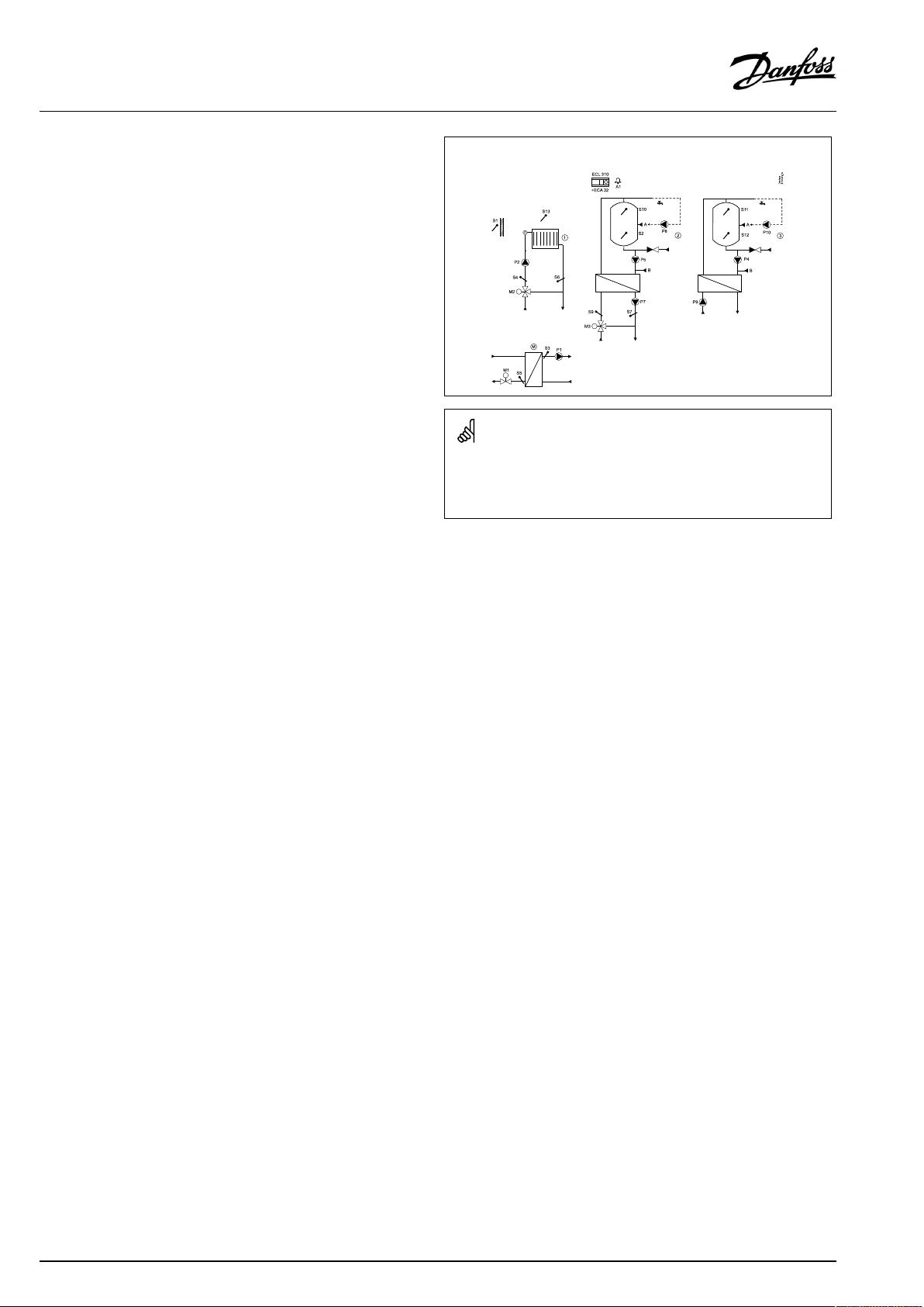
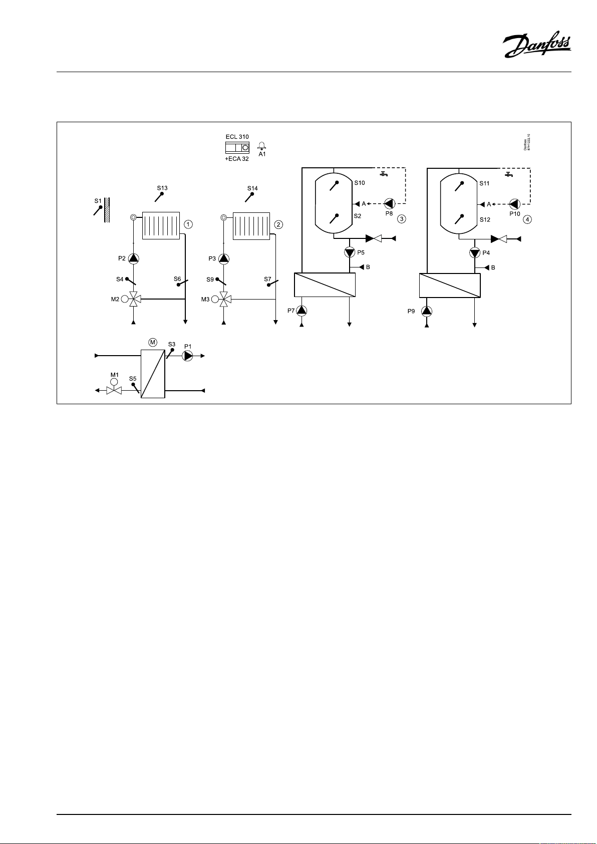
P330.13
Onemastercircuit,twoheatingcircuitsandtwoDHWchargingcircuitsassub-circuits.
AQ120086463710en-010501
©Danfoss|2021.06|27
Page 28

OperatingGuideECLComfort310,applicationP330
SpecialsettingsfortypeP330.13
Navigation:
Themastercircuitreactsondemandinthesub-circuit(s).
Sub-circuit(s)
Settingsforsub-circuit(s)inordertosenddemandtomastercircuit:
MENU\Settings\Application:'SenddesiredT'
Mastercircuit
Settingsformastercircuitinordertoreactondemandinsub-circuit(s):
MENU\Settings(M)\Application:'Demandoffset'
*Thisvalueisaddedtotheheatdemandvaluefromsub-circuit(s)
DHWcirculationpipe
TheDHWcirculationpipecanbeconnectedtotheDHWtankat'A'forinternal
circulationortotheheatexchangerat'B'forexternalcirculation.
(InternalDHWcirculation)MENU\Settings\Application:'Cont.Tcontrol'
(ExternalDHWcirculation)MENU\Settings\Application:'Cont.Tcontrol'
IDno.:
1x500
1x017
1x054
1x054
Recommendedsetting:
ON
3K*
OFF
ON
28|©Danfoss|2021.06
AQ120086463710en-010501
Page 29
OperatingGuideECLComfort310,applicationP330
P330.14
Onemastercircuitwithbuffertank,twoheatingcircuitsandoneDHWchargingcircuitsassub-circuits.
SpecialsettingsfortypeP330.14
Navigation:
Themastercircuitreactsondemandinthesub-circuit(s).
Sub-circuit(s)
Settingsforsub-circuit(s)inordertosenddemandtomastercircuit:
MENU\Settings\Application:'SenddesiredT'
Mastercircuit
Settingsformastercircuitinordertoreactondemandinsub-circuit(s):
MENU\Settings(M)\Application:'Demandoffset'
*Thisvalueisaddedtotheheatdemandvaluefromsub-circuit(s)
DHWcirculationpipe
TheDHWcirculationpipecanbeconnectedtotheDHWtankat'A'forinternal
circulationortotheheatexchangerat'B'forexternalcirculation.
IDno.:
1x500
1x017
Recommendedsetting:
ON
3K*
(InternalDHWcirculation)MENU\Settings\Application:'Cont.Tcontrol'
(ExternalDHWcirculation)MENU\Settings\Application:'Cont.Tcontrol'
AQ120086463710en-010501
1x054
1x054
OFF
ON
©Danfoss|2021.06|29
Page 30
OperatingGuideECLComfort310,applicationP330
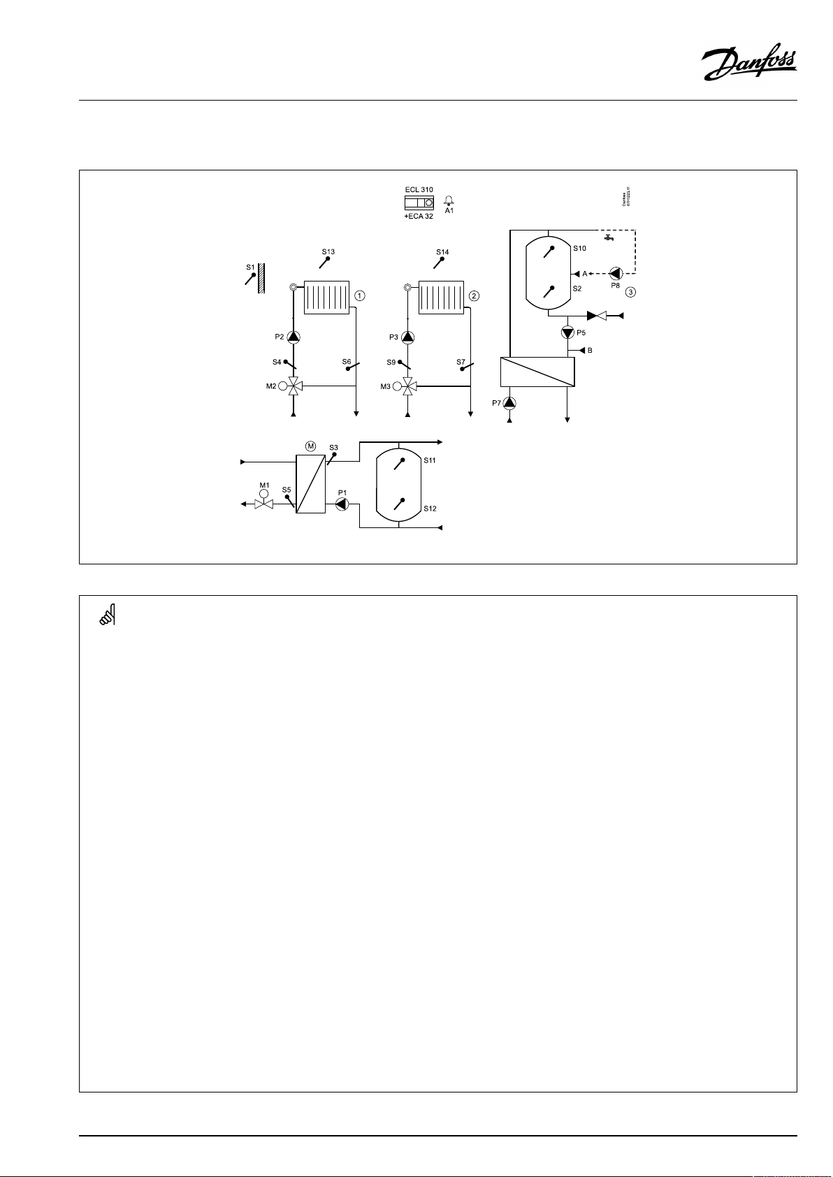
P330.15
Onemastercircuit.OneheatingcircuitandoneDHWchargingcircuitsassub-circuits.
SpecialsettingsfortypeP330.15
Navigation:
Themastercircuitreactsondemandinthesub-circuit(s).
Sub-circuit(s)
Settingsforsub-circuit(s)inordertosenddemandtomastercircuit:
MENU\Settings\Application:'SenddesiredT'
Mastercircuit
Settingsformastercircuitinordertoreactondemandinsub-circuit(s):
MENU\Settings(M)\Application:'Demandoffset'
*Thisvalueisaddedtotheheatdemandvaluefromsub-circuit(s)
DHWcirculationpipe
TheDHWcirculationpipecanbeconnectedtotheDHWtankat'A'forinternal
circulationortotheheatexchangerat'B'forexternalcirculation.
IDno.:
1x500
1x017
Recommendedsetting:
ON
3K*
(InternalDHWcirculation)MENU\Settings\Application:'Cont.Tcontrol'
(ExternalDHWcirculation)MENU\Settings\Application:'Cont.Tcontrol'
30|©Danfoss|2021.06
1x054
1x054
AQ120086463710en-010501
OFF
ON
Page 31

OperatingGuideECLComfort310,applicationP330
2.3Mounting
2.3.1MountingtheECLComfortcontroller
SeetheInstallationGuidewhichisdeliveredtogetherwiththe
ECLComfortcontroller.
Foreasyaccess,youshouldmounttheECLComfortcontrollernear
thesystem.
ECLComfort210/296/310canbemounted
•onawall
•onaDINrail(35mm)
ECLComfort296canbemounted
•inapanelcut-out
ECLComfort210canbemountedinanECLComfort310basepart
(forfutureupgrade).
Screws,PGcableglandsandrawlplugsarenotsupplied.
LockingtheECLComfort210/310controller
InordertofastentheECLComfortcontrollertoitsbasepart,secure
thecontrollerwiththelockingpin.
Topreventinjuriestopersonsorthecontroller,thecontrollerhasto
besecurelylockedintothebase.Forthispurpose,pressthelocking
pinintothebaseuntilaclickisheardandthecontrollernolonger
canberemovedfromthebase.
Ifthecontrollerisnotsecurelylockedintothebasepart,thereisarisk
thatthecontrollerduringoperationcanunlockfromthebaseandthe
basewithterminals(andalsothe230Va.c.connections)areexposed.
Topreventinjuriestopersons,alwaysmakesurethatthecontroller
issecurelylockedintoitsbase.Ifthisisnotthecase,thecontroller
shouldnotbeoperated!
AQ120086463710en-010501
©Danfoss|2021.06|31
Page 32

OperatingGuideECLComfort310,applicationP330
Mountingonawall
Mountthebasepartonawallwithasmoothsurface.Establishthe
electricalconnectionsandpositionthecontrollerinthebasepart.
Securethecontrollerwiththelockingpin.
MountingonaDINrail(35mm)
MountthebasepartonaDINrail.Establishtheelectrical
connectionsandpositionthecontrollerinthebasepart.Secure
thecontrollerwiththelockingpin.
Theeasywaytolockthecontrollertoitsbaseorunlockitistousea
screwdriveraslever.
DismountingtheECLComfortcontroller
Inordertoremovethecontrollerfromthebasepart,pulloutthe
lockingpinbymeansofascrewdriver.Thecontrollercannowbe
removedfromthebasepart.
Theeasywaytolockthecontrollertoitsbaseorunlockitistousea
screwdriveraslever.
32|©Danfoss|2021.06
AQ120086463710en-010501
Page 33

OperatingGuideECLComfort310,applicationP330
2.3.2MountingtheRemoteControlUnitsECA30/31
Selectoneofthefollowingmethods:
•Mountingonawall,ECA30/31
•Mountinginapanel,ECA30
Screwsandrawlplugsarenotsupplied.
Mountingonawall
MountthebasepartoftheECA30/31onawallwithasmooth
surface.Establishtheelectricalconnections.PlacetheECA30/
31inthebasepart.
BeforeremovingtheECLComfortcontrollerfromthebasepart,ensure
thatthesupplyvoltageisdisconnected.
Mountinginapanel
MounttheECA30inapanelusingtheECA30framekit(ordercode
no.087H3236).Establishtheelectricalconnections.Securethe
framewiththeclamp.PlacetheECA30inthebasepart.TheECA
30canbeconnectedtoanexternalroomtemperaturesensor.
TheECA31mustnotbemountedinapanelifthehumidity
functionistobeused.
AQ120086463710en-010501
©Danfoss|2021.06|33
Page 34

OperatingGuideECLComfort310,applicationP330
2.3.3MountingtheinternalI/OmoduleECA32orECA35
TheECA32module(ordercodeno.087H3202)orECA35module
(ordercodeno.087H3205)canbeinsertedintotheECLComfort
310/310Bbasepartforadditionalinputandoutputsignalsin
relevantapplications.
ECA32
ECA35
34|©Danfoss|2021.06
AQ120086463710en-010501
Page 35

OperatingGuideECLComfort310,applicationP330
2.4Placingthetemperaturesensors
2.4.1Placingthetemperaturesensors
Itisimportantthatthesensorsaremountedinthecorrectposition
inyoursystem.
Thetemperaturesensormentionedbelowaresensorsusedforthe
ECLComfort210/296/310serieswhichnotallwillbeneeded
foryourapplication!
Outdoortemperaturesensor(ESMT)
Theoutdoorsensorshouldbemountedonthatsideofthebuilding
whereitislesslikelytobeexposedtodirectsunshine.Itshouldnot
beplacedclosetodoors,windowsorairoutlets.
Flowtemperaturesensor(ESMU,ESM-11orESMC)
Placethesensormax.15cmfromthemixingpoint.Insystems
withheatexchanger,DanfossrecommendsthattheESMU-typeto
beinsertedintotheexchangerflowoutlet.
Makesurethatthesurfaceofthepipeiscleanandevenwhere
thesensorismounted.
Returntemperaturesensor(ESMU,ESM-11orESMC)
Thereturntemperaturesensorshouldalwaysbeplacedsothatit
measuresarepresentativereturntemperature.
Roomtemperaturesensor
(ESM-10,ECA30/31RemoteControlUnit)
Placetheroomsensorintheroomwherethetemperatureistobe
controlled.Donotplaceitonoutsidewallsorclosetoradiators,
windowsordoors.
Boilertemperaturesensor(ESMU,ESM-11orESMC)
Placethesensoraccordingtotheboilermanufacturer’s
specification.
Airducttemperaturesensor(ESMB-12orESMUtypes)
Placethesensorsothatitmeasuresarepresentativetemperature.
DHWtemperaturesensor(ESMUorESMB-12)
PlacetheDHWtemperaturesensoraccordingtothemanufacturer’s
specification.
Slabtemperaturesensor(ESMB-12)
Placethesensorinaprotectiontubeintheslab.
ESM-11:Donotmovethesensorafterithasbeenfastenedinorderto
avoiddamagetothesensorelement.
ESM-11,ESMCandESMB-12:Useheatconductingpasteforquick
measurementofthetemperature.
ESMUandESMB-12:Usingasensorpockettoprotectthesensorwill,
however,resultinaslowertemperaturemeasurement.
AQ120086463710en-010501
©Danfoss|2021.06|35
Page 36

OperatingGuideECLComfort310,applicationP330
Pt1000temperaturesensor(IEC751B,1000Ω/0°C)
Relationshipbetweentemperatureandohmicvalue:
36|©Danfoss|2021.06
AQ120086463710en-010501
Page 37

OperatingGuideECLComfort310,applicationP330
2.5Electricalconnections
2.5.1Electricalconnections230Va.c.
Warning
ElectricconductorsonPCB(PrintedCircuitBoard)forsupplyvoltage,
relaycontactsandtriacoutputsdonothavemutualsafetydistanceof
minimum6mm.Theoutputsarenotallowedtobeusedasgalvanic
separated(voltfree)outputs.
Ifagalvanicseparatedoutputisneeded,anauxiliaryrelayis
recommended.
24Voltcontrolledunits,forexampleactuators,aretobecontrolledby
meansofECLComfort310,24Voltversion.
SafetyNote
Necessaryassembly,start-up,andmaintenanceworkmustbe
performedbyqualifiedandauthorizedpersonnelonly.
Locallegislationsmustberespected.Thiscomprisesalsocablesize
andisolation(reinforcedtype).
Thecommongroundterminalisusedforconnectionofrelevant
components(pumps,motorizedcontrolvalves).
SeealsotheInstallationGuide(deliveredwiththeapplicationkey)
forapplicationspecificconnections.
AfusefortheECLComfortinstallationismax.10Atypically.
TheambienttemperaturerangefortheECLComfortinoperationis
0-55°C.Exceedingthistemperaturerangecanresultinmalfunctions.
Installationmustbeavoidedifthereisariskforcondensation(dew).
ECL210/310
AQ120086463710en-010501
©Danfoss|2021.06|37
Page 38

OperatingGuideECLComfort310,applicationP330
2.5.2Electricalconnections,230Va.c.,powersupply,pumps,dampers,motorizedcontrolvalvesetc.
ConnectionsforP330,ingeneral:
SeealsotheInstallationGuide(deliveredwiththeapplicationkey)forapplicationspecificconnections.
ApplicationP330
Terminal
19
18
A1
17
P5
16
15
P4
14
13
P3
12
P2
11
P1
10
9
8
7
M1
6
M1
5
4
M2
3
M2
2
M3
1
M3
*Relaycontacts:4Aforohmicload,2Aforinductiveload
Description
Phaseforcirculationpump/DHWchargingpump/Alarm
Alarm
Circulationpump/DHWchargingpump
Phaseforcirculationpump/chargingpump
Circulationpump/DHWchargingpump
Phaseforcirculationpump/chargingpump
Circulationpump
Circulationpump
Circulationpump/chargingpump
Supplyvoltage230Va.c.-neutral(N)
Supplyvoltage230Va.c.-live(L)
Phaseformotorizedcontrolvalveoutput
Motorizedcontrolvalve-opening
Motorizedcontrolvalve-closing
Phaseformotorizedcontrolvalveoutput
Motorizedcontrolvalve-opening
Motorizedcontrolvalve-closing
Motorizedcontrolvalve-opening
Motorizedcontrolvalve-closing
Max.load
4(2)A/230Va.c.*
4(2)A/230Va.c.*
4(2)A/230Va.c.*
4(2)A/230Va.c.*
4(2)A/230Va.c.*
4(2)A/230Va.c.*
0.2A/230Va.c.
0.2A/230Va.c.
0.2A/230Va.c.
0.2A/230Va.c.
0.2A/230Va.c.
0.2A/230Va.c.
Factoryestablishedjumpers:
5to8,9to14,Lto5andLto9,Nto10
38|©Danfoss|2021.06
AQ120086463710en-010501
Page 39

OperatingGuideECLComfort310,applicationP330
Wirecrosssection:0.5-1.5mm²
Incorrectconnectioncandamagetheelectronicoutputs.
Max.2x1.5mm²wirescanbeinsertedintoeachscrewterminal.
AQ120086463710en-010501
©Danfoss|2021.06|39
Page 40

OperatingGuideECLComfort310,applicationP330
2.5.3ECA32,relayoutputsingeneral
ConnectionsforP330,ingeneral:
SeealsotheInstallationGuide(deliveredwiththeapplicationkey)forapplicationspecificconnections.
ECA32,0-10Voutput
ConnectionsforP330,ingeneral:
SeealsotheInstallationGuide(deliveredwiththeapplicationkey)forapplicationspecificconnections.
40|©Danfoss|2021.06
AQ120086463710en-010501
Page 41

OperatingGuideECLComfort310,applicationP330
2.5.4Electricalconnections,safetythermostats,230Va.c.
Withsafetythermostat,1–stepclosing:
Motorizedcontrolvalvewithoutsafetyfunction
Withsafetythermostat,1–stepclosing:
Motorizedcontrolvalvewithsafetyfunction
AQ120086463710en-010501
©Danfoss|2021.06|41
Page 42

OperatingGuideECLComfort310,applicationP330
Withsafetythermostat,2–stepclosing:
Motorizedcontrolvalvewithsafetyfunction
42|©Danfoss|2021.06
WhenSTisactivatedbyahightemperature,thesafetycircuitinthe
motorizedcontrolvalveclosesthevalveimmediately.
WhenST1isactivatedbyahightemperature(theTRtemperature),the
motorizedcontrolvalveisclosedgradually.Atahighertemperature
(theSTtemperature),thesafetycircuitinthemotorizedcontrolvalve
closesthevalveimmediately.
AQ120086463710en-010501
Page 43

OperatingGuideECLComfort310,applicationP330
Wirecrosssection:0.5-1.5mm²
Incorrectconnectioncandamagetheelectronicoutputs.
Max.2x1.5mm²wirescanbeinsertedintoeachscrewterminal.
AQ120086463710en-010501
©Danfoss|2021.06|43
Page 44

OperatingGuideECLComfort310,applicationP330
2.5.5Electricalconnections,Pt1000temperaturesensorsandsignals
SeetheInstallationGuide(deliveredwiththeapplicationkey)for
sensorandinputconnections.
ConnectionsforP330,ingeneral:
SeealsotheInstallationGuide(deliveredwiththeapplicationkey)
forapplicationspecificconnections.
TerminalSensor/description
29and30
28and30
27and30
26and30
25and30
24and30
23and30
22and30
20and30
S1
Outdoortemperature
sensor*
Temperaturesensor
S2
S3
Flowtemperaturesensor**
S4
Flowtemperaturesensor**
S5
(Optional)Return
temperaturesensor
S6
(Optional)Return
temperaturesensor
S7
(Optional)Return
temperaturesensor
S8
Voltagesignal(0-10V)for
externalcontrolofdesired
flowtemperature,heating
circuit1orMastercircuit.
S9
Flowtemperaturesensor** 21and30
S10
UpperDHWtank
temperaturesensor***/
flowtemperaturesensor**
Type
(recomm.)
ESMT
ESM-11/ESMB/
ESMC/ESMU
ESM-11/ESMB/
ESMC/ESMU
ESM-11/ESMB/
ESMC/ESMU
ESM-11/ESMB/
ESMC/ESMU
ESM-11/ESMB/
ESMC/ESMU
ESM-11/ESMB/
ESMC/ESMU
ESM-11/ESMB/
ESMC/ESMU
ESMB/ESMU
ESM-11/ESMB/
ESMC/ESMU
*
Iftheoutdoortemperaturesensorisnotconnectedorthe
cableisshort-circuited,thecontrollerassumesthatthe
outdoortemperatureis0(zero)°C.
**
Thesensormustalwaysbeconnectedinordertohavethe
desiredfunctionality.Ifthesensorisnotconnectedorthe
cableisshort-circuited,themotorizedcontrolvalvecloses
(safetyfunction).
***
Thissensorisusedifonlyonetanktemperaturesensoris
required.
Factoryestablishedjumper:
30tocommonterminal.
Wirecrosssectionforsensorconnections:Min.0.4mm².
Totalcablelength:Max.200m(allsensorsincl.internalECL485
communicationbus)
Cablelengthsofmorethan200mmaycausenoisesensibility(EMC).
44|©Danfoss|2021.06
AQ120086463710en-010501
Page 45

OperatingGuideECLComfort310,applicationP330
Connectionofvoltagesignal(0–10V)toS8forexternalcontrol
ofdesiredflowtemperature
Electricalconnections,ECA32
ConnectionsforP330,ingeneral:
SeealsotheInstallationGuide(deliveredwiththeapplicationkey)
forapplicationspecificconnections.
TerminalSensor/description
50and49
51and49
52and49
53and49
54and49
55and49
S11
Uppertank/buffertank
temperaturesensor
S12
Lowertank/buffertank
temperature
S13
(Optional)Room
temperaturesensor
S14
(Optional)Room
temperaturesensor
S15
(Optional)Room
temperaturesensor
S16
(Optional)Room
temperaturesensor
Type
(recomm.)
ESMB/ESMU
ESMB/ESMU
ESM-10
ESM-10
ESM-10
ESM-10
AQ120086463710en-010501
©Danfoss|2021.06|45
Page 46

OperatingGuideECLComfort310,applicationP330
2.5.6Electricalconnections,ECA30/31
Terminal
ECL
Terminal
ECA30/31
30
31
4
1
322
333
4
5
*
Afteranexternalroomtemperaturesensorhasbeenconnected,
Description
Twistedpair
Twistedpair
Ext.roomtemperature
sensor*
Type
(recomm.)
Cable2x
twistedpair
ESM-10
ECA30/31mustberepowered.
ThecommunicationtotheECA30/31mustbesetupintheECL
Comfortcontrollerin'ECAaddr.'
TheECA30/31mustbesetupaccordingly.
AfterapplicationsetuptheECA30/31isreadyafter2–5min.A
progressbarintheECA30/31isdisplayed.
46|©Danfoss|2021.06
Iftheactualapplicationcontainstwoheatingcircuits,itispossible
toconnectanECA30/31toeachcircuit.Theelectricalconnections
aredoneinparallel.
Max.2ECA30/31canbeconnectedtoanECLComfort310controller
ortoECLComfort210/296/310controllersinamaster-slavesystem.
SetupproceduresforECA30/31:Seesection‘Miscellaneous’ .
AQ120086463710en-010501
Page 47

OperatingGuideECLComfort310,applicationP330
ECAinformationmessage:
‘Applicationreq.newerECA’:
Thesoftware(firmware)ofyourECAdoesnotcomplywiththe
software(firmware)ofyourECLComfortcontroller.Pleasecontact
yourDanfosssalesoffice.
Someapplicationsdonotcontainfunctionsrelatedtoactualroom
temperature.TheconnectedECA30/31willonlyfunctionasremote
control.
Totalcablelength:Max.200m(allsensorsincl.internalECL485
communicationbus).
Cablelengthsofmorethan200mmaycausenoisesensibility(EMC).
AQ120086463710en-010501
©Danfoss|2021.06|47
Page 48

OperatingGuideECLComfort310,applicationP330
2.5.7Electricalconnections,master/slavesystems
Thecontrollercanbeusedasmasterorslaveinmaster/slave
systemsviatheinternalECL485communicationbus(2xtwisted
paircable).
TheECL485communicationbusisnotcompatiblewiththeECL
businECLComfort110,200,300and301!
Terminal
Description
Type
(recomm.)
30
Commonterminal
+12V*,ECL485communicationbus
31
*OnlyforECA30/31andmaster/
slavecommunication
32
B,ECL485communicationbus
33
A,ECL485communicationbus
Cable2x
twistedpair
ECL485buscable
MaximumrecommendedlengthoftheECL485busiscalculatedlike
this:
Subtract"TotallengthofallinputcablesofallECLcontrollersinthe
master-slavesystem"from200m.
Simpleexamplefortotallengthofallinputcables,3xECL:
1xECL
3xECL
3xECLReturntemp.sensor:
3xECLRoomtemp.sensor:
Total:
Outdoortemp.sensor:
Flowtemp.sensor:
15m
18m
18m
30m
81m
2.5.8Electricalconnections,communication
Electricalconnections,Modbus
ECLComfort210:Non-galvanicisolatedModbusconnections
ECLComfort296:GalvanicisolatedModbusconnections
ECLComfort310:GalvanicisolatedModbusconnections
MaximumrecommendedlengthoftheECL485bus:
200-81m=119m
48|©Danfoss|2021.06
AQ120086463710en-010501
Page 49

OperatingGuideECLComfort310,applicationP330
2.5.9Electricalconnections,communication
Electricalconnections,M-bus
ECLComfort210:Notimplemented
ECLComfort296:Onboard,non-galvanicisolated.Max.cable
length50m.
ECLComfort310:Onboard,non-galvanicisolated.Max.cable
length50m.
AQ120086463710en-010501
©Danfoss|2021.06|49
Page 50

OperatingGuideECLComfort310,applicationP330
2.6InsertingtheECLApplicationKey
2.6.1InsertingtheECLApplicationKey
TheECLApplicationKeycontains
•theapplicationanditssubtypes,
•currentlyavailablelanguages,
•factorysettings:e.g.schedules,desiredtemperatures,
limitationvaluesetc.Itisalwayspossibletorecoverthefactory
settings,
•memoryforusersettings:specialuser/systemsettings.
Afterhavingpowered-upthecontroller,differentsituationsmight
beexisting:
1.Thecontrollerisnewfromthefactory,theECLApplicationKey
isnotinserted.
2.Thecontrolleralreadyrunsanapplication.TheECLApplication
Keyisinserted,buttheapplicationneedstobechanged.
3.Acopyofthecontrollerssettingsisneededforconfiguring
anothercontroller.
ECLComfort210/310
ECLComfort210/310
Usersettingsare,amongothers,desiredroomtemperature,desired
DHWtemperature,schedules,heatcurve,limitationvaluesetc.
Systemsettingsare,amongothers,communicationset-up,display
brightnessetc.
50|©Danfoss|2021.06
AQ120086463710en-010501
Page 51

OperatingGuideECLComfort310,applicationP330
Automaticupdateofcontrollersoftware(firmware):
Thesoftwareofthecontrollerisupdatedautomaticallywhenthekey
isinserted(asofcontrollerversion1.11(ECL210/310)andversion
1.58(ECL296)).Thefollowinganimationwillbeshownwhenthe
softwareisbeingupdated:
Progressbar
Duringupdate:
•DonotremovetheKEY
Ifthekeyisremovedbeforethehour-glassisshown,youhave
tostartafresh.
•Donotdisconnectthepower
Ifthepowerisinterruptedwhenthehour-glassisshown,the
controllerwillnotwork.
•Manualupdateofcontrollersoftware(firmware):
Seethesection"Automatic/manualupdateoffirmware"
The“Keyoverview”doesnotinform—throughECA30/31—about
thesubtypesoftheapplicationkey.
Keyinserted/notinserted,description:
ECLComfort210/310,controllerversionslowerthan1.36:
-
Takeouttheapplicationkey;for20minutes
settingscanbechanged.
-
Powerupthecontrollerwithoutthe
applicationkeyinserted;for20minutes
settingscanbechanged.
ECLComfort210/310,controllerversions1.36andup:
-
Takeouttheapplicationkey;for20minutes
settingscanbechanged.
-
Powerupthecontrollerwithoutthe
applicationkeyinserted;settingscannotbe
changed.
ECLComfort296,controllerversions1.58andup:
-
Takeouttheapplicationkey;for20minutes
settingscanbechanged.
-
Powerupthecontrollerwithoutthe
applicationkeyinserted;settingscannotbe
changed.
AQ120086463710en-010501
©Danfoss|2021.06|51
Page 52

OperatingGuideECLComfort310,applicationP330
ApplicationKey:Situation1
Thecontrollerisnewfromthefactory,theECLApplicationKey
isnotinserted.
AnanimationfortheECLApplicationKeyinsertionisdisplayed.
InserttheApplicationKey.
ApplicationKeynameandVersionisindicated(example:A266
Ver.1.03).
IftheECLApplicationKeyisnotsuitableforthecontroller,a"cross"
isdisplayedovertheECLApplicationKey-symbol.
Action:Purpose:
Selectlanguage
Confirm
Selectapplication(subtype)
Somekeyshaveonlyoneapplication.
Confirmwith‘Yes’
Set'Time&Date'
Turnandpushthedialtoselectand
change'Hours' ,'Minutes','Date',
'Month'and'Year' .
Choose''Next'
Confirmwith‘Yes’
Goto‘Aut.daylight’
Choosewhether‘ Aut.daylight´*
shouldbeactiveornot
*‘Aut.daylight’istheautomaticchangeoverbetweensummer
andwintertime.
DependingonthecontentsoftheECLApplicationKey,procedure
AorBistakingplace:
A
TheECLApplicationkeycontainsfactorysettings:
Thecontrollerreads/transfersdatafromtheECLApplicationKey
toECLcontroller.
Examples:
YESorNO
Theapplicationisinstalled,andthecontrollerresetsandstartsup.
B
TheECLApplicationkeycontainschangedsystemsettings:
Pushthedialrepeatedly.
’NO’:
’YES*:
Ifthekeycontainsusersettings:
Pushthedialrepeatedly.
‘NO:
‘YES*:
*If‘YES’cannotbechosen,theECLApplicationKeydoesnot
containanyspecialsettings.
Choose‘Startcopying’andconfirmwith'Yes'.
52|©Danfoss|2021.06
OnlyfactorysettingsfromtheECLApplicationKeywill
becopiedtothecontroller.
Specialsystemsettings(differingfromthefactory
settings)willbecopiedtothecontroller.
OnlyfactorysettingsfromtheECLApplicationKeywill
becopiedtothecontroller.
Specialusersettings(differingfromthefactorysettings)
willbecopiedtothecontroller.
AQ120086463710en-010501
Page 53

OperatingGuideECLComfort310,applicationP330
(Example):
The"i"intheupperrightcornerindicatesthat-besidesthefactory
settings-thesubtypealsocontainsspecialuser/systemssettings.
ApplicationKey:Situation2
Thecontrolleralreadyrunsanapplication.TheECLApplication
Keyisinserted,buttheapplicationneedstobechanged.
TochangetoanotherapplicationontheECLApplicationKey,the
currentapplicationinthecontrollermustbeerased(deleted).
BeawarethattheApplicationKeymustbeinserted.
Action:Purpose:
Choose‘MENU’inanycircuit
Confirm
Choosethecircuitselectoratthetop
rightcornerinthedisplay
Confirm
Choose‘Commoncontrollersettings’
Confirm
Choose‘Keyfunctions’
Confirm
Choose‘Eraseapplication’
Confirmwith‘Yes’
Thecontrollerresetsandisreadytobeconfigured.
Followtheproceduredescribedinsituation1.
Examples:
AQ120086463710en-010501
©Danfoss|2021.06|53
Page 54

OperatingGuideECLComfort310,applicationP330
ApplicationKey:Situation3
Acopyofthecontrollerssettingsisneededforconfiguring
anothercontroller.
Thisfunctionisused
•forsaving(backup)ofspecialuserandsystemsettings
•whenanotherECLComfortcontrollerofthesametype(210,
296or310)mustbeconfiguredwiththesameapplicationbut
user/systemsettingsdifferfromthefactorysettings.
HowtocopytoanotherECLComfortcontroller:
Action:Purpose:
Choose‘MENU’
Confirm
Choosethecircuitselectoratthetop
rightcornerinthedisplay
Confirm
Choose'Commoncontrollersettings'
Confirm
Goto‘Keyfunctions’
Confirm
Choose‘Copy’
Confirm
Choose‘To’ .
‘ECL’or‘KEY’willbeindicated.Choose
’ECL’orKEY’
Pushthedialrepeatedlytochoose
copydirection
Choose‘Systemsettings’or‘User
settings’
Pushthedialrepeatedlytochoose
‘Yes’or‘No’in‘Copy’ .Pushtoconfirm.
Choose‘Startcopying’
TheApplicationKeyorthecontroller
isupdatedwithspecialsystemoruser
settings.
Examples:
*
’ECL’or‘KEY’ .
**
‘NO’or‘YES’
*
‘ECL’:
‘KEY’:
**
‘NO’:
‘YES’:
54|©Danfoss|2021.06
DatawillbecopiedfromtheApplicationKeytothe
ECLController.
DatawillbecopiedfromtheECLControllertothe
ApplicationKey.
ThesettingsfromtheECLcontrollerwillnotbecopied
totheApplicationKeyortotheECLComfortcontroller.
Specialsettings(differingfromthefactorysettings)will
becopiedtotheApplicationKeyortotheECLComfort
controller.IfYEScannotbechosen,therearenospecial
settingstobecopied.
AQ120086463710en-010501
Page 55

OperatingGuideECLComfort310,applicationP330
Language
Atapplicationupload,alanguagemustbeselected.*
IfanotherlanguagethanEnglishisselected,theselectedlanguage
ANDEnglishwillbeuploadedintotheECLcontroller.
ThismakesserviceeasyforEnglishspeakingservicepeople,just
becausetheEnglishlanguagemenuscanbevisiblebychanging
theactualsetlanguageintoEnglish.
(Navigation:MENU>Commoncontroller>System>Language)
Iftheuploadedlanguageisnotsuitable,theapplicationmustbe
erased.UserandSystemsettingscanbesavedontheapplication
keybeforeerasing.
Afternewuploadwithpreferredlanguage,theexistingUserand
Systemsettingscanbeuploaded.
*)
(ECLComfort310,24Volt)Iflanguagecannotbeselected,the
powersupplyisnota.c.(alternatingcurrent).
2.6.2ECLApplicationKey,copyingdata
Generalprinciples
Whenthecontrollerisconnectedandoperating,youcancheck
andadjustallorsomeofthebasicsettings.Thenewsettingscan
bestoredontheKey.
Factorysettingscanalwaysberestored.
HowtoupdatetheECLApplicationKeyaftersettingshave
beenchanged?
AllnewsettingscanbestoredontheECLApplicationKey.
Howtostorefactorysettinginthecontrollerfromthe
ApplicationKey?
PleasereadtheparagraphconcerningApplicationKey,Situation
1:Thecontrollerisnewfromthefactory,theECLApplicationKey
isnotinserted.
HowtostorepersonalsettingsfromthecontrollertotheKey?
PleasereadtheparagraphconcerningApplicationKey,Situation3:
Acopyofthecontrollerssettingsisneededforconfiguringanother
controller
Asamainrule,theECLApplicationKeyshouldalwaysremainin
thecontroller.IftheKeyisremoved,itisnotpossibletochange
settings.
Makeanoteofnewsettingsinthe'Settingsoverview'table.
DonotremovetheECLApplicationKeywhilecopying.Thedataon
theECLApplicationKeycanbedamaged!
ItispossibletocopysettingsfromoneECLComfortcontrollerto
anothercontrollerprovidedthatthetwocontrollersarefromthesame
series(210or310).
Furthermore,whentheECLComfortcontrollerhasbeenuploaded
withanapplicationkey,minimumversion2.44,itispossibletoupload
personalsettingsfromapplicationkeys,minimumversion2.14.
AQ120086463710en-010501
©Danfoss|2021.06|55
Page 56

OperatingGuideECLComfort310,applicationP330
The“Keyoverview”doesnotinform—throughECA30/31—about
thesubtypesoftheapplicationkey.
Keyinserted/notinserted,description:
ECLComfort210/310,controllerversionslowerthan1.36:
-
Takeouttheapplicationkey;for20minutes
settingscanbechanged.
-
Powerupthecontrollerwithoutthe
applicationkeyinserted;for20minutes
settingscanbechanged.
ECLComfort210/310,controllerversions1.36andup:
-
Takeouttheapplicationkey;for20minutes
settingscanbechanged.
-
Powerupthecontrollerwithoutthe
applicationkeyinserted;settingscannotbe
changed.
ECLComfort296,controllerversions1.58andup:
-
Takeouttheapplicationkey;for20minutes
settingscanbechanged.
-
Powerupthecontrollerwithoutthe
applicationkeyinserted;settingscannotbe
changed.
56|©Danfoss|2021.06
AQ120086463710en-010501
Page 57

OperatingGuideECLComfort310,applicationP330
2.7Checklist
IstheECLComfortcontrollerreadyforuse?
Makesurethatthecorrectpowersupplyisconnectedtoterminals9and10(230Vor24V).
Makesurethecorrectphaseconditionsareconnected:
230V:Live=terminal9andNeutral=terminal10
24V:SP=terminal9andSN=terminal10
Checkthattherequiredcontrolledcomponents(actuator,pumpetc.)areconnectedtothecorrectterminals.
Checkthatallsensors/signalsareconnectedtothecorrectterminals(see'Electricalconnections').
Mountthecontrollerandswitchonthepower.
IstheECLApplicationKeyinserted(see'InsertingtheApplicationKey').
DoestheECLComfortcontrollercontainanexistingapplication(see'InsertingtheApplicationKey').
Isthecorrectlanguagechosen(see'Language'in'Commoncontrollersettings').
Isthetime&datesetcorrectly(see'Time&Date'in'Commoncontrollersettings').
Istherightapplicationchosen(see'Identifyingthesystemtype').
Checkthatallsettingsinthecontroller(see'Settingsoverview')aresetorthatthefactorysettingscomplywithyour
requirements.
Choosemanualoperation(see'Manualcontrol').Checkthatvalvesopenandclose,andthatrequiredcontrolled
components(pumpetc.)startandstopwhenoperatedmanually.
Checkthatthetemperatures/signalsshowninthedisplaymatchtheactualconnectedcomponents.
Havingcompletedthemanualoperationcheck,choosecontrollermode(scheduled,comfort,savingorfrostprotection).
AQ120086463710en-010501
©Danfoss|2021.06|57
Page 58

OperatingGuideECLComfort310,applicationP330
2.8Navigation,ECLApplicationKeyP330
Parameterlist,applicationP330,Heating
Home
MENU
Schedule
Settings
Heating
Flow
temperature
Room
limit
Return
limit
Flow/Actual
power
limit
Optimization
Control
par.
IDnos.
1x178
1x179
1x182
1x183
1x015
1x031
1x032
1x033
1x034
1x035
1x036
1x037
1x085
1x029
1x119
1x117
1x118
1x116
1x112
1x113
1x10⁹
1x115
1x011
1x012
1x013
1x014
1x026
1x020
1x021
1x179
1x174
1x184
1x185
1x186
1x187
1x189
Function
Schedule
Heatcurve
Temp.max.
Temp.min.
Ext.desiredT
Infl.-max.
Infl.-min.
Adapt.time
HighToutX1
LowlimitY1
LowToutX2
HighlimitY2
Infl.-max.
Infl.-min.
Adapt.time
Priority
DHW,ret.T
limit
Actuallimit
HighToutX1
LowlimitY1
LowToutX2
HighlimitY2
Adapt.time
Filterconstant
Inputtype
Units
Autosaving
Boost
Ramp
Optimizer
Pre-stop
Basedon
Totalstop
Summer,
cut-out
Motorpr.
Xp
Tn
Mrun
Nz
Min.act.time
P330allapplications(P330.1,P330.2,P330.3etc.)
.1
.2.3
(((((((((((((((
(((((((((((((((
(((((((((((((((
(((((((((((((((
(((((
(((((((((((((((
(((((((((((((((
(((((((((((((((
(((((((((((((((
(((((((((((((((
(((((((((((((((
(((((((((((((((
(((((((((((((((
(((((((((((((((
(((((((((((((((
(((((((((((((((
(((((
(((((((((((((((
(((((((((((((((
(((((((((((((((
(((((((((((((((
(((((((((((((((
(((((((((((((((
(((((((((((((((
(((((((((((((((
(((((((((((((((
(((((((((((((((
(((((((((((((((
(((((((((((((((
(((((((((((((((
(((((((((((((((
(((((((((((((((
(((((((((((((((
(((((((((((((((
(((((((((((((((
(((((((((((((((
(((((((((((((((
(((((((((((((((
(((((((((((((((
(((((((((((((((
(((((((((((((((
.4.5
.7
.6
.8.9.10
.11
.12.13
.14.15
58|©Danfoss|2021.06
AQ120086463710en-010501
Page 59

OperatingGuideECLComfort310,applicationP330
Parameterlist,applicationP330,Heating,continued
Home
MENU
Settings
HolidayHoliday
Alarm
Influence
overview
Heating
Application
Temp.
monitor.
Alarm
overview
Des.flow
T
IDnos.
1x010
1x017
1x050
1x500
1x022
1x023
1x052
1x077
1x078
1x040
1x093
1x141
1x142
1x147
1x148
1x149
1x150
Function
ECAaddr.
Demandoffset
Pdemand
SenddesiredT
Pexercise
Mexercise
DHWpriority
PfrostT
PheatT
Ppost-run
Frostpr.T
Ext.input
Ext.mode
Upperdiff.
Lowerdiff.
Delay
Lowesttemp.
Influence
source
P330allapplications(P330.1,P330.2,P330.3etc.)
.1
.2.3
(((((((((((((((
(((((
(((((
(((((((((((((((
(((((((((((((((
(((((((((((((((
(((((((((((((((
(((((((((((((((
(((((((((((((((
(((((((((((((((
(((((((((((((((
(((((((((((((((
(((((((((((((((
(((((((((((((((
(((((((((((((((
(((((((((((((((
(((((((((((((((
(((((((((((((((
(((((((((((((((
(((((((((((((((
.4.5
.7
.6
.8.9.10
.11
.12.13
.14.15
AQ120086463710en-010501
©Danfoss|2021.06|59
Page 60

OperatingGuideECLComfort310,applicationP330
Parameterlist,applicationP330,DHW
Home
MENU
Schedule
Schedule
Circ.pu.
Settings
HolidayHoliday
DHWIDnos.
Tanktemperature
Return
limit
Flow/Actual
power
limit
Control
par.
Application
Antibacteria
1x193
1x195
1x194
1x152
1x192
1x196
1x030
1x035
1x036
1x037
1x111
1x112
1x113
1x10⁹
1x115
1x174
1x184
1x185
1x186
1x187
1x189
1x055
1x054
1x041
1x042
1x500
1x076
1x093
1x141
1x142
Function
Schedule
Schedule
Charge
difference
Startdifference
Stopdifference
Max.chargeT
Tankstartdiff.
Tankstopdiff.
Limit
Infl.-max.
Infl.-min.
Adapt.time
Limit
Adapt.time
Filterconstant
Inputtype
Units
Motorpr.
Xp
Tn
Mrun
Nz
Min.act.time
Circ.Ppriority
Cont.Tcontrol
DHWPpost-run
Char.Ppost-run
SenddesiredT
Circ.PfrostT
Frostpr.T
Ext.input
Ext.mode
Day,days
Starttime
Duration
DesiredT
P330allapplications(P330.1,P330.2,P330.3etc.)
.1
.2.3
.4.5
(((((((((
(((((((((
(((((((((
(((((((((
(((((((((
(((((((((
(((
(((
(((
(((
(((
(((
(((
(((
(((
(((
(((
(((
(((
(((
(((
(((
(((((((((
(((((((((
(((((((((
(((((((((
(((((((((
(((((((((
(((((((((
(((((((((
(((((((((
(((((((((
(((((((((
(((((((((
(((((((((
(((((((((
.7
.6
.8.9.10
.11
.12.13
.14.15
(
(
Alarm
Influence
overview
60|©Danfoss|2021.06
Temp.
monitor.
Alarm
overview
Des.
DHWT
1x147
1x148
1x149
1x150
Upperdiff.
Lowerdiff.
Delay
Lowesttemp.
Influencesource
(((
(((
(((
(((
(((
(((((((((
AQ120086463710en-010501
Page 61

OperatingGuideECLComfort310,applicationP330
Parameterlist,applicationP330,Commoncontroller
Home
Com-
MENU
Settings
Settings
(M)
Alarm
(M)
HolidayHoliday
mon
controller
Flow
temperature
Return
limit
Flow/
power
limit
Control
par.
Application
IDnos.
1x193
1x194
1x195
1x178
1x179
1x029
1x017
1x022
1x023
1x052
1x077
1x078
1x040
1x141
Function
Time&date
Charge
difference
Stopdifference
Startdifference
Temp.max.
Temp.min.
Ext.desiredT
Seesettingsfor
Heating
DHW,ret.T
limit
Seesettingsfor
Heating
Seesettingsfor
Heating
Demandoffset
Pexercise
Mexercise
DHWpriority
PfrostT
PheatT
Ppost-run
Ext.input
Seesettingsfor
Heating
P330allapplications(P330.1,P330.2,P330.3etc.)
.1
.2.3
(((((((((((((((
((((((((((((((
.4.5
.7
.6
((((((((((
((((((((((
((((((((((
((((((((((
((((((((((
((((((((((
((((((((((
((((((((((
((((((((((
((((((((((
((((((((((
((((((((((
((((((((((
((((((((((
((((((((((
.8.9.10
.11
.12.13
.14.15
(
(
(
((
AQ120086463710en-010501
Input
overview
Input
overview
(M)
Log
Log(M)
Output
override
Key
functions
System
(((((((((((((((
((((((((((
(((((((((((((((
((((((((((
(((((((((((((((
(((((((((((((((
(((((((((((((((
©Danfoss|2021.06|61
Page 62

OperatingGuideECLComfort310,applicationP330
Parameterlist,applicationP330,Commoncontroller
Home
Com-
MENU
Key
functions
SystemECLversion
mon
controller
IDnos.
Function
New
application
Application
Factorysetting
Copy
Keyoverview
Extension
Ethernet
Portalconfig.
M-busconfig.
Energymeters
Rawinput
overview
Alarm
Display
Communica-
tion
Language
P330allapplications(P330.1,P330.2,P330.3etc.)
.1
.2.3
(((((((((((((((
(((((((((((((((
(((((((((((((((
(((((((((((((((
(((((((((((((((
(((((((((((((((
(((((((((((((((
(((((((((((((((
(((((((((((((((
(((((((((((((((
(((((((((((((((
(((((((((((((((
(((((((((((((((
(((((((((((((((
(((((((((((((((
(((((((((((((((
.4.5
.7
.6
.8.9.10
.11
.12.13
.14.15
62|©Danfoss|2021.06
AQ120086463710en-010501
Page 63

OperatingGuideECLComfort310,applicationP330
3.0Dailyuse
3.1Howtonavigate
Younavigateinthecontrollerbyturningthedialleftorrightto
thedesiredposition().
Thedialhasabuilt-inaccellerator.Thefasteryouturnthedial,the
fasteritreachesthelimitsofanywidesettingrange.
Thepositionindicatorinthedisplay(
youare.
Pushthedialtoconfirmyourchoices().
Thedisplayexamplesarefromatwo-circuitapplication:One
heatingcircuit()andonedomestichot-water(DHW)circuit().
Theexamplesmightdifferfromyourapplication.
)willalwaysshowyouwhere
ExampleshowsECL210/310
Heatingcircuit():DHWcircuit();
Somegeneralsettingswhichapplytotheentirecontrollerare
locatedinaspecificpartofthecontroller.
Toenter‘Commoncontrollersettings’:
Action:Purpose:
Choose‘MENU’inanycircuit
Confirm
Choosethecircuitselectoratthetop
rightcornerinthedisplay
Confirm
Choose‘Commoncontrollersettings’
Confirm
Examples:
Circuitselector
AQ120086463710en-010501
©Danfoss|2021.06|63
Page 64

OperatingGuideECLComfort310,applicationP330
3.2Understandingthecontrollerdisplay
ThissectiondescribesthefunctioningeneralfortheECLComfort
210/296/310series.Theshowndisplaysaretypicalandnot
applicationrelated.Theymightdifferfromthedisplaysinyour
application.
Choosingafavoritedisplay
Yourfavoritedisplayisthedisplayyouhavechosenasthedefault
display.Thefavoritedisplaywillgiveyouaquickoverviewofthe
temperaturesorunitsthatyouwanttomonitoringeneral.
Ifthedialhasnotbeenactivatedfor20min.,thecontrollerwill
reverttotheoverviewdisplayyouhavechosenasfavorite.
Toshiftbetweendisplays:Turnthedialuntilyoureachthedisplay
selector(
turntochooseyourfavoriteoverviewdisplay.Pushthedialagain.
)atthebottomrightsideofthedisplay.Pushthedialand
Heatingcircuit
Overviewdisplay1informsabout:
actualoutdoortemperature,controllermode,
actualroomtemperature,desiredroomtemperature.
Overviewdisplay2informsabout:
actualoutdoortemperature,trendinoutdoortemperature,
controllermode,max.andmin.outdoortemperaturessince
midnightaswellasdesiredroomtemperature.
Overviewdisplay3informsabout:
date,actualoutdoortemperature,controllermode,time,desired
roomtemperatureaswellasshowsthecomfortscheduleofthe
currentday.
Overviewdisplay4informsabout:
stateofthecontrolledcomponents,actualflowtemperature,
(desiredflowtemperature),controllermode,returntemperature
(limitationvalue),influenceondesiredflowtemperature.
ThevalueabovetheV2symbolindicates0–100%oftheanalogue
signal(0–10V).
Note:
Anactualflowtemperaturevaluemustbepresent,otherwisethe
circuit'scontrolvalvewillclose.
Overviewdisplay1:Overviewdisplay2:
Overviewdisplay3:Overviewdisplay4:
Exampleofoverviewdisplaywith
Influenceindication:
Example,favoritedisplay1in
A230.3,wheremin.desiredroom
temperatureisindicated(22.7):
Dependentonthechosendisplay,theoverviewdisplaysforthe
heatingcircuitinformyouabout:
•actualoutdoortemperature(-0.5)
•controllermode()
•actualroomtemperature(24.5)
•desiredroomtemperature(20.7°C)
•trendinoutdoortemperature(
)
•min.andmax.outdoortemperaturessincemidnight(
•date(23.02.2010)
•time(7:43)
•comfortscheduleofthecurrentday(0-12-24)
•stateofthecontrolledcomponents(M2,P2)
•actualflowtemperature(49°C),(desiredflowtemperature(31))
•returntemperature(24°C)(limitationtemperature(50))
64|©Danfoss|2021.06
)
AQ120086463710en-010501
Page 65

OperatingGuideECLComfort310,applicationP330
Thesettingofthedesiredroomtemperatureisimportantevenifa
roomtemperaturesensor/RemoteControlUnitisnotconnected.
Ifthetemperaturevalueisdisplayedas
"--"
thesensorinquestionisnotconnected.
"---"
thesensorconnectionisshort-circuited.
DHWcircuit
Overviewdisplay1informsabout:
actualDHWtemperature,controllermode,desiredDHW
temperatureaswellasthecomfortscheduleofthecurrentday.
Overviewdisplay2informsabout:
stateofthecontrolledcomponents,actualDHWtemperature,
(desiredDHWtemperature),controllermode,returntemperature
(limitationvalue),influenceondesiredDHWtemperature.
Dependentonchosendisplay,theoverviewdisplaysfortheDHW
circuitinformyouabout:
•actualDHWtemperature(50.3)
•controllermode(
)
•desiredDHWtemperature(50°C)
•comfortscheduleofthecurrentday(0-12-24)
•stateofthecontrolledcomponents(M1,P1)
•actualDHWtemperature(50°C),(desiredDHWtemperature(50))
•returntemperature(--°C)(limitationtemperature(30))
Settingthedesiredtemperature
Dependingonthechosencircuitandmode,itispossibletoenter
alldailysettingsdirectlyfromtheoverviewdisplays(seealsothe
nextpageconcerningsymbols).
Overviewdisplay1:Overviewdisplay2:
Exampleofoverviewdisplaywith
Influenceindication:
AQ120086463710en-010501
©Danfoss|2021.06|65
Page 66

OperatingGuideECLComfort310,applicationP330
Settingthedesiredroomtemperature
Thedesiredroomtemperaturecaneasilybeadjustedinthe
overviewdisplaysfortheheatingcircuit.
Action:Purpose:
Desiredroomtemperature
Confirm
Adjustthedesiredroomtemperature
Confirm
Thisoverviewdisplayinformsaboutoutdoortemperature,actual
roomtemperatureaswellasdesiredroomtemperature.
Thedisplayexampleisforcomfortmode.Ifyouwanttochange
thedesiredroomtemperatureforsavingmode,choosethemode
selectorandselectsaving.
Examples:
20.5
21.0
Thesettingofthedesiredroomtemperatureisimportantevenifa
roomtemperaturesensor/RemoteControlUnitisnotconnected.
SettingthedesiredDHWtemperature
ThedesiredDHWtemperaturecaneasilybeadjustedinthe
overviewdisplaysfortheDHWcircuit.
Action:Purpose:
DesiredDHWtemperature
Confirm
AdjustthedesiredDHWtemperature
Confirm
InadditiontotheinformationaboutdesiredandactualDHW
temperature,thetoday'sscheduleisvisible.
Thedisplayexampleindicatesthatthecontrollerisinscheduled
operationandincomfortmode.
Examples:
50
55
66|©Danfoss|2021.06
AQ120086463710en-010501
Page 67

OperatingGuideECLComfort310,applicationP330
Settingthedesiredroomtemperature,ECA30/ECA31
Thedesiredroomtemperaturecanbesetexactlyasinthe
controller.However,othersymbolscanbepresentinthedisplay
(pleasesee'Whatdothesymbolsmean?').
WiththeECA30/ECA31youcanoverridethedesiredroom
temperaturesetinthecontrollertemporarilybymeansoftheoverride
functions:
AQ120086463710en-010501
©Danfoss|2021.06|67
Page 68

OperatingGuideECLComfort310,applicationP330
3.3Ageneraloverview:Whatdothesymbolsmean?
Symbol
Description
Outdoortemp.
Relativehumidityindoor
Roomtemp.
DHWtemp.
Positionindicator
Scheduledmode
Comfortmode
Savingmode
Frostprotectionmode
Manualmode
Standby
Coolingmode
Symbol
Temperature
Mode
Description
Alarm
Letter
Event
Monitoringtemperaturesensor
connection
Displayselector
Max.andmin.value
Trendinoutdoortemperature
Windspeedsensor
Sensornotconnectedornotused
Sensorconnectionshort-circuited
Fixedcomfortday(holiday)
Activeinfluence
Heatingactive(+)
Coolingactive(-)
Activeoutputoverride
Optimizedstartorstoptime
Heating
Cooling
DHW
Commoncontrollersettings
PumpON
PumpOFF
FanON
FanOFF
Actuatoropens
Actuatorcloses
Actuator,analoguecontrol
signal
Pump/fanspeed
DamperON
Circuit
Controlled
component
Numberofheatexchangers
Additionalsymbols,ECA30/31:
Symbol
InECA30/31onlythesymbolsthatarerelevanttotheapplicationin
thecontrolleraredisplayed.
Description
ECARemoteControlUnit
Connectionaddress(master:15,slaves:1-9)
15
Dayoff
Holiday
Relaxing(extendedcomfortperiod)
Goingout(extendedsavingperiod)
68|©Danfoss|2021.06
DamperOFF
AQ120086463710en-010501
Page 69

OperatingGuideECLComfort310,applicationP330
3.4Monitoringtemperaturesandsystemcomponents
ThissectiondescribesthefunctioningeneralfortheECLComfort
210/296/310series.Theshowndisplaysaretypicalandnot
applicationrelated.Theymightdifferfromthedisplaysinyour
application.
Heatingcircuit
Theoverviewdisplayintheheatingcircuitensuresaquick
overviewoftheactualand(desired)temperaturesaswellasthe
actualstateofthesystemcomponents.
Displayexample:
49°C
(31)
24°C
(50)
DHWcircuit
TheoverviewdisplayintheDHWcircuitensuresaquickoverview
oftheactualand(desired)temperaturesaswellastheactualstate
ofthesystemcomponents.
Displayexample(heatexchanger):
50°C
(50)
(30)
Flowtemperature
Desiredflowtemperature
Returntemperature
Returntemperaturelimitation
Flowtemperature
Desiredflowtemperature
--
Returntemperature:sensornotconnected
Returntemperaturelimitation
Displayexamplewithheatexchanger:
Inputoverview
Anotheroptiontogetaquickoverviewofmeasuredtemperatures
isthe'Inputoverview'whichisvisibleinthecommoncontroller
settings(howtoenterthecommoncontrollersettings,see
‘Introductiontocommoncontrollersettings’ .)
Asthisoverview(seedisplayexample)onlystatesthemeasured
actualtemperatures,itisread-only.
AQ120086463710en-010501
©Danfoss|2021.06|69
Page 70

OperatingGuideECLComfort310,applicationP330
3.5Influenceoverview
ThissectiondescribesthefunctioningeneralfortheECLComfort
210/296/310series.Theshowndisplaysaretypicalandnot
applicationrelated.Theymightdifferfromthedisplaysinyour
application.
Themenugivesanoverviewoftheinfluencesonthedesired
flowtemperature.Itdiffersfromapplicationtoapplicationwhich
parametersarelisted.Itcanbehelpfulinaservicesituationto
explainunexpectedconditionsortemperaturesamongothers.
Ifthedesiredflowtemperatureisinfluenced(corrected)byoneor
moreparameters,itisindicatedbyasmalllinewitharrow-down,
arrow-upordouble-arrow:
Arrow-down:
Theparameterinquestionreducesthedesiredflowtemperature.
Arrow-up:
Theparameterinquestionincreasesthedesiredflowtemperature.
Double-arrow:
Theparameterinquestioncreatesanoverride(e.g.Holiday).
Straightline:
Noactiveinfluence.
Intheexample,thearrowinthesymbolpointsdownwardsfor
'Roomlim. ' .Thismeansthattheactualroomtemperatureis
higherthanthedesiredroomtemperaturewhichagainresultsina
decreaseofthedesiredflowtemperature.
ExampleofoverviewdisplaywithInfluenceindication:
70|©Danfoss|2021.06
AQ120086463710en-010501
Page 71

OperatingGuideECLComfort310,applicationP330
3.6Manualcontrol
Itispossibletomanuallycontroltheinstalledcomponents.
Manualcontrolcanonlybeselectedinfavoritedisplaysinwhich
thesymbolsforthecontrolledcomponents(valve,pumpetc.)are
visible.
Action:Purpose:
Choosemodeselector
Confirm
Choosemanualmode
Confirm
Choosepump
Confirm
SwitchONthepump
SwitchOFFthepump.
Confirmpumpmode
Choosemotorizedcontrolvalve
Confirm
Openthevalve
Stopopeningthevalve
Closethevalve
Examples:
ControlledcomponentsCircuitselector
Duringmanualoperation:
•Allcontrolfunctionsaredeactivated
•Outputoverrideisnotpossible
•Frostprotectionisnotactive
Stopclosingthevalve
Confirmvalvemode
Toleavemanualcontrol,usethemodeselectortoselectthe
desiredmode.Pushthedial.
Manualcontrolistypicallyusedwhencommisioningthe
installation.Thecontrolledcomponents,valve,pumpetc.,canbe
controlledforcorrectfunction.
Whenmanualcontrolisselectedforonecircuit,itisautomatically
selectedforallcircuits!
AQ120086463710en-010501
©Danfoss|2021.06|71
Page 72

OperatingGuideECLComfort310,applicationP330
3.7Schedule
3.7.1Setyourschedule
ThissectiondescribesthescheduleingeneralfortheECLComfort
210/296/310series.Theshowndisplaysaretypicalandnot
applicationrelated.Theymightdifferfromthedisplaysinyour
application.Insomeapplications,however,theremightbemore
thanoneschedule.Additionalschedulescanbefoundin‘Common
controllersettings’ .
Thescheduleconsistsofa7-dayweek:
=
M
Monday
=
T
Tuesday
=
W
Wednesday
=
T
Thursday
=
F
Friday
=
S
Saturday
=
S
Sunday
Theschedulewillday-by-dayshowyouthestartandstoptimesof
yourcomfortperiods(heating/DHWcircuits).
Changingyourschedule:
Action:
Purpose:
Choose'MENU'inanyoftheoverview
displays
Confirm
Confirmthechoice'Schedule'
Choosethedaytochange
Confirm*
GotoStart1
Confirm
Adjustthetime
Confirm
GotoStop1,Start2etc.etc.
Returnto'MENU'
Confirm
Choose'Yes'or'No'in'Save'
Confirm
Examples:
*Severaldayscanbemarked
Thechosenstartandstoptimeswillbevalidforallthechosendays
(inthisexampleThursdayandSaturday).
Youcansetmax.3comfortperiodsaday.Youcandeleteacomfort
periodbysettingstartandstoptimestothesamevalue.
72|©Danfoss|2021.06
Eachcircuithasitsownschedule.Tochangetoanothercircuit,goto
'Home',turnthedialandchoosethedesiredcircuit.
Thestartandstoptimescanbesetinhalf-hourly(30min.)intervals.
AQ120086463710en-010501
Page 73

OperatingGuideECLComfort310,applicationP330
4.0Settingsoverview
AllparametersrelatedtoheatingandDHWarelistedascircuit1.
Itisrecommendabletomakeanoteofanychangedsettingsintheemptycolumns.
SettingIDPage
Heatcurve
Ext.desiredT
Day
Starttime
Duration
DesiredT
ECAaddr.(choiceofRemoteControlUnit)
Autosaving(savingtemp.dependentonoutdoortemp.)
Boost
Ramp(referenceramping)
Optimizer(optimizingtimeconstant)
Adapt.time(adaptiontime)
Demandoffset
Basedon(optimizationbasedonroom/outdoortemp.)
Totalstop
Pexercise(pumpexercise)
Mexercise(valveexercise)
Pre-stop(optimizedstoptime)
DHW,ret.Tlimit
HighToutX1(returntemp.limitation,highlimit,X-axis)
LowlimitY1(returntemp.limitation,lowlimit,Y-axis)
LowToutX2(returntemp.limitation,lowlimit,X-axis)
HighlimitY2(returntemp.limitation,highlimit,Y-axis)
Infl.-max.(returntemp.limitation-max.influence)
Infl.-min.(returntemp.limitation-min.influence)
Adapt.time(adaptationtime)
Ppost-run
DHWPpost-run
Char.Ppost-run
Pdemand(P330.1-P330.5)
DHWpriority(closedvalve/normaloperation)
Cont.Tcontrol
Circ.Ppriority
Circ.PfrostT
PfrostT
PheatT(heatdemand)
Priority(priorityforreturntemp.limitation)
Frostpr.T(frostprotectiontemperature)
Frostpr.T(frostprotectiontemperature)
1x01096
1x01188
1x01288
1x01389
1x01489
1x01579
1x01796
1x02090
1x02190
1x02296
1x02396
1x02691
1x02981
1x03181
1x03281
1x03382
1x03482
1x03582
1x03683
1x03783
1x04097
1x041103
1x042103
1x05097
1x05297
1x054103
1x055103
1x076103
1x07798
1x07898
1x08584
1x09398
1x093104
Factorysettingsincircuit(s)
1
76
77
109
109
110
110
2
AQ120086463710en-010501
©Danfoss|2021.06|73
Page 74

OperatingGuideECLComfort310,applicationP330
SettingIDPage
Inputtype
Actual(actualfloworpower)
Actuallimit(limitationvalue)
Adapt.time(adaptationtime)
Filterconstant
Units
HighlimitY2(flow/powerlimitation,highlimit,Y-axis)
LowlimitY1(flow/powerlimitation,lowlimit,Y-axis)
LowToutX2(flow/powerlimitation,lowlimit,X-axis)
HighToutX1(flow/powerlimitation,highlimit,X-axis)
Ext.input(externaloverride)
Ext.mode(externaloverridemode)
Upperdifference
Lowerdifference
Delay
Lowesttemp.
Max.chargeT
Motorpr.(motorprotection)
Temp.min.(flowtemp.limit,min.)
Temp.max.(flowtemp.limit,max.)
Summer,cut-out(limitforheatingcut-out)
Infl.-max.(roomtemp.limitation,max.)
Infl.-min.(roomtemp.limitation,min.)
Xp(proportionalband)
Tn(integrationtimeconstant)
Mrun(runningtimeofthemotorizedcontrolvalve)
Nz(neutralzone)
Min.act.time(min.activationtimegearmotor)
Tankstartdiff.(P330.14)
Chargedifference
Stopdifference
Startdifference
Tankstopdiff.(P330.14)
SenddesiredT
SenddesiredT
1x10985
1x11085
1x111
1x11286
1x11386
1x115
1x11686
1x117
1x11887
1x11987
1x141
1x14299
1x147111
1x148
1x149
1x150
1x152104
1x174
1x17777
1x178
1x17991
1x18279
1x18380
1x18493
1x18593
1x18693
1x18794
1x18994
1x192104
1x193105
1x194105
1x195106
1x196107
1x500101
1x500107
Factorysettingsincircuit(s)
1
85
86
86
98
111
111
111
93
77
2
74|©Danfoss|2021.06
AQ120086463710en-010501
Page 75

OperatingGuideECLComfort310,applicationP330
5.0Settings
5.1IntroductiontoSettings
Descriptionsofsettings(parameter'sfunctions)aredividedinto
groupsasusedintheECLComfort210/296/310controller's
menustructure.Examples:"Flowtemperature" ,"Roomlimit"and
soon.Eachgroupstartswithageneralexplanation.
Thedescriptionsofeachparameterareinnumericorder,relatedto
theparameter'sIDnumbers.Youmightcomeacrossdifferences
betweentheorderinthisOperatingGuideandtheECLComfort
210/296/310controllers.
Someparameterdescriptionsarerelatedtospecificapplication
subtypes.Thismeansthatyoumightnotseetherelatedparameter
intheactualsubtypeintheECLcontroller.
Thenote"SeeAppendix… "referstotheAppendixattheendof
thisOperatingGuide,whereparameter'ssettingrangesandfactory
settingsarelisted.
Thenavigationhints(forexampleMENU>Settings>Returnlimit
…)covermultiplesubtypes.
AQ120086463710en-010501
©Danfoss|2021.06|75
Page 76

OperatingGuideECLComfort310,applicationP330
5.2Flowtemperature
TheECLComfortcontrollerdeterminesandcontrolstheflow
temperaturerelatedtotheoutdoortemperature.Thisrelationship
iscalledtheheatcurve.
Theheatcurveissetbymeansof6coordinatepoints.Thedesired
flowtemperatureissetat6pre-definedoutdoortemperature
values.
Theshownvaluefortheheatcurveisanaveragevalue(slope),
basedontheactualsettings.
Desiredflowtemperature
Outdoor
temp.
Desiredflowtemp.
A
BC
Your
settings
-30°C45°C75°C95°C
-15°C40°C60°C90°C
-5°C35°C50°C80°C
0°C32°C45°C70°C
5°C30°C40°C60°C
15°C25°C28°C35°C
A:Exampleforfloorheating
B:Factorysettings
C:Exampleforradiatorheating(highdemand)
MENU>Settings>Flowtemperature
Heatcurve
1
0.1...4.01.0
Theheatcurvecanbechangedintwoways:
1.Thevalueoftheslopeischanged(seeheatcurveexamples
onnextpage)
2.Thecoordinatesoftheheatcurvearechanged
Changethevalueoftheslope:
Pushthedialtoenter/changetheslopevalueoftheheatcurve
(example:1.0).
Whentheslopeoftheheatcurveischangedbymeansoftheslope
value,thecommonpointforallheatcurveswillbeadesiredflow
temperature=24.6°Catanoutdoortemperature=20°Canda
desiredroomtemperature=20.0°C.
Slopechanges
Coordinatechanges
Changethecoordinates:
Pushthedialtoenter/changethecoordinatesoftheheatcurve
(example:-30,75).
Theheatcurverepresentsthedesiredflowtemperaturesat
differentoutdoortemperaturesandatadesiredroomtemperature
of20°C.
Ifthedesiredroomtemperatureischanged,thedesiredflow
temperaturealsochanges:
(DesiredroomT-20)×HC×2.5
where"HC"istheHeatCurveslopeand"2.5"isaconstant.
76|©Danfoss|2021.06
Thecalculatedflowtemperaturecanbeinfluencedbythe‘Boost’and
‘Ramp’functionsetc.
Example:
Heatcurve:
Desiredflowtemp.:
Desiredroomtemp.:
Calculation(22–20)×1.0×2.5=
Result:
Thedesiredflowtemperaturewillbecorrectedfrom50°Cto55°C.
1.0
50°C
22°C
5
AQ120086463710en-010501
Page 77

OperatingGuideECLComfort310,applicationP330
Choosingaheatcurveslope
Theheatcurvesrepresentthedesiredflowtemperatureatdifferentoutdoortemperaturesandatadesiredroomtemperatureof20°C.
Thesmallarrows()indicate6differentoutdoortemperaturevaluesatwhichyoucanchangetheheatcurve.
MENU>Settings>Flowtemperature
Temp.min.(flowtemp.limit,min.)
SeeAppendix“ParameterIDoverview”
Setthemin.flowtemperatureforthesystem.Thedesiredflow
1x177
‘Temp.min.’isoverruledif'Totalstop'isactiveinSavingmodeor
'Cut-out'isactive.
‘Temp.min.’canbeoverruledbytheinfluencefromthereturn
temperaturelimitation(see'Priority').
temperaturewillnotbelowerthanthissetting.Adjustthefactory
setting,ifrequired.
Thesettingfor‘Temp.max. ’hashigherprioritythan‘Temp.min.’ .
MENU>Settings>Flowtemperature
Temp.max.(flowtemp.limit,max.)
1x178
Thesettingof‘heatcurve’ispossibleforheatingcircuitsonly.
SeeAppendix“ParameterIDoverview”
Setthemax.flowtemperatureforthesystem.Thedesiredflow
temperaturewillnotbehigherthanthissetting.Adjustthefactory
setting,ifrequired.
Thesettingfor‘Temp.max. ’hashigherprioritythan‘Temp.min.’ .
AQ120086463710en-010501
©Danfoss|2021.06|77
Page 78

OperatingGuideECLComfort310,applicationP330
Externalsignalfordesiredflowtemperature
Thecircuit1intheapplicationsP330.1-P330.5andtheMaster
CircuitintheapplicationsP330.6-P330.14canbecontrolledbyan
externalsignalfordesiredflowtemperature.
Avoltage(0-10V)canbeappliedtotheinputterminalS8inorder
todeterminethedesiredflowtemperature.
ThemeasuredvoltageoninputS8mustbeconvertedtoa
temperaturevaluebythecontroller.Whenthevoltagegetshigher,
thedesiredflowtemperatureincreases.
Thefollowingsettingssetupthescaling.
MENU>Settings>Flowtemperature
Ext.desiredT
CircuitSettingrange
Read-outonly
Theactualdesiredflowtemperatureisindicatedbytheunit°C.
Factorysetting
None
Read-out:
--:
°C:
Externalvoltagesignalisnotconnected.
Externalvoltagesignalconvertedtodesiredflow
temperature.
Example:Relationshipbetweeninputvoltageanddisplayeddesiredflow
temperature
Desiredflowtemp.(°C)
Volt
Thisexampleshowsthat1voltcorrespondsto10.0°Cand10volt
correspondto100°C.
Pushthedialtoseethegraphandenterthevaluesetsfortheinput
voltage(1and10volt)anddisplayeddesiredflowtemperature.
Desiredflowtemperature:
10...120°C
Fixedvoltagesettings:1Vand10V
Factorysettings:
(1,10)and(10,100)
Thismeansthatthe‘Desiredflowtemperature’is10°Cat1.0V
and100°Cat10V.
Typically,thehigherthevoltage,thehigherthedisplayeddesired
flowtemperature.
Theexternalvoltagesignalmustbehigherthan1.0Vinorderto
activatetheoverride.
78|©Danfoss|2021.06
AQ120086463710en-010501
Page 79

OperatingGuideECLComfort310,applicationP330
5.3Roomlimit
Thissectionisonlyrelevantifyouhaveinstalledaduct/room
temperaturesensororaRemoteControlUnit.
Thecontrolleradjuststhedesiredflowtemperaturetocompensate
forthedifferencebetweenthedesiredandtheactualduct/room
temperature.
Iftheduct/roomtemperatureishigherthanthedesiredvalue,the
desiredflowtemperaturecanbereduced.
The'Infl.-max.'(Influence,max.duct/roomtemp.)determines
howmuchthedesiredflowtemperatureshouldbereduced.
Usethisinfluencetypetoavoidatoohighduct/roomtemperature.
Thecontrollerwillallowforfreeheatgains,i.e.solarradiationor
heatfromafireplaceetc.
Iftheduct/roomtemperatureislowerthanthedesiredvalue,the
desiredflowtemperaturecanbeincreased.
The'Infl.-min.'(Influence,min.duct/roomtemperature)
determineshowmuchthedesiredflowtemperatureshouldbe
increased.
Usethisinfluencetypetoavoidatoolowduct/roomtemperature.
Thiscoulde.g.becausedbywindysurroundings.
Atypicalsettingwillbe-4.0for'Infl.-max.'and4.0for'Infl.-min. '
ParametersindicatedwithanIDno.like"1x607"meanauniversal
parameter.
xstandsforcircuit/parametergroup.
MENU>Settings>Roomlimit
Adapt.time(adaptiontime)
Controlshowfasttheactualroomtemperatureadaptstothedesiredroom
temperature(Icontrol).
1x015
SeeAppendix“ParameterIDoverview”
OFF:
Thecontrolfunctionisnotinfluencedbythe'Adapt.
time'.
1:
50:
Thedesiredroomtemperatureisadaptedquickly.
Thedesiredroomtemperatureisadaptedslowly.
Theadaptationfunctioncancorrectthedesiredflowtemperature
withmax.8Kxheatcurvevalue.
AQ120086463710en-010501
©Danfoss|2021.06|79
Page 80

OperatingGuideECLComfort310,applicationP330
MENU>Settings>Roomlimit
Infl.-max.(roomtemp.limitation,max.)
Determineshowmuchthedesiredflowtemperaturewillbeinfluenced
(decreased)iftheactualroomtemperatureishigherthanthedesiredroom
temperature(Pcontrol).
SeeAppendix“ParameterIDoverview”
-9.9:
0.0:
Theroomtemperaturehasabiginfluence.
Theroomtemperaturehasnoinfluence.
Influence
1x182
‘Infl.-min.’(min.limitation)
Desiredroomtemperature
Actualroomtemperature
‘Infl.-max. ’(max.limitation)
The‘Infl.-max.’and'Infl.-min. 'determinehowmuchtheroom
temperatureshouldinfluencethedesiredflowtemperature.
Ifthe‘Infl. ’factoristoohighand/orthe‘Adapt.time’toolow,thereis
ariskofunstablecontrol.
Example1:
Theactualroomtemperatureis2degreestoohigh.
The‘Infl.-max.’issetto-4.0.
The‘Infl.-min.’issetto0.0.
Theslopeis1.8(see'Heatcurve'in'Flowtemperature').
Result:
Thedesiredflowtemperatureischangedby(2x-4.0x1.8)
–14.4degrees.
MENU>Settings>Roomlimit
Infl.-min.(roomtemp.limitation,min.)
0.0....9.90.0
Determineshowmuchthedesiredflowtemperaturewillbeinfluenced
(increased)iftheactualroomtemperatureislowerthanthedesiredroom
temperature(Pcontrol).
SeeAppendix“ParameterIDoverview”
0.0:
9.9:
Theroomtemperaturehasnoinfluence.
Theroomtemperaturehasabiginfluence.
Example2:
Theactualroomtemperatureis3degreestoolow.
The‘Infl.-max.’issetto-4.0.
The‘Infl.-min.’issetto2.0.
Theslopeis1.8(see'Heatcurve'in'Flowtemperature').
Result:
Thedesiredflowtemperatureischangedby(3x2.0x1.8)
10.8degrees.
1x183
80|©Danfoss|2021.06
AQ120086463710en-010501
Page 81

OperatingGuideECLComfort310,applicationP330
5.4Returnlimit
Thereturntemperaturelimitationisbasedontheoutdoor
temperature.Typicallyindistrictheatingsystemsahigherreturn
temperatureisacceptedatadecreaseinoutdoortemperature.The
relationshipbetweenthereturntemperaturelimitsandoutdoor
temperatureissetintwocoordinates.
Theoutdoortemperaturecoordinatesaresetin'HighToutX1'
and'LowToutX2' .Thereturntemperaturecoordinatesaresetin
'HighlimitY2'and'LowlimitY1' .
Thecontrollerautomaticallychangesthedesiredflowtemperature
toobtainanacceptablereturntemperaturewhenthereturn
temperaturefallsbeloworgetshigherthanthecalculatedlimit.
ThislimitationisbasedonaPIregulationwhereP('Infl.'factor)
respondsquicklytodeviationsandI('Adapt.time')responds
slowerandovertimeremovesthesmalloffsetsbetweenthe
desiredandactualvalues.Thisisdonebychangingthedesired
flowtemperature.
MENU>Settings>Returnlimit
DHW,ret.Tlimit
WhenanaddressedslaveisactiveinDHW-tankheating/charging,the
returntemperaturelimitationinthemastercanbeset.
1x029
Returntemperaturelimitation
HighlimitY2
LowlimitY1
Outdoortemp.
LowToutX2
Thecalculatedlimitisshowninbrackets()inthemonitoringdisplay.
Seethesection"Monitoringtemperaturesandsystemcomponents" .
HighToutX1
Notes:
•Themastercircuitmustbesettoreactonthedesiredflowtemperature
intheslave(s).See"Demandoffset"(ID11017).
•Theslave(s)mustbesettosendits/theirdesiredflowtemperaturetothe
master.See"SenddesiredT"(ID1x500).
SeeAppendix“ParameterIDoverview”
OFF:
Noinfluencefromslaves.Thereturntemperature
limitationisrelatedtosettingsin"Returnlimit" .
10–
110°C:
Returntemperaturelimitationvaluewhenslaveisin
DHWtankheating/chargingoperation.
MENU>Settings>Returnlimit
HighToutX1(returntemp.limitation,highlimit,X-axis)
Settheoutdoortemperatureforthelowreturntemperaturelimitation.
#1#=Master,exampleA266,address15
#2#=Slave,exampleA237,address9
#3#=Slave,exampleA367,address6
SomeexamplesofapplicationswithDHW-tankheating/chargingare:
•A217,A237,A247,A367,A377
Sub-circuitsareconsideredasslavestoo.
P330.1...P330.5:Parameter1x029ispresentincircuit1.
P330.6...P330.15:Parameter1x029ispresentinMastercircuit(M).
1x031
SeeAppendix“ParameterIDoverview”
ThecorrespondingYcoordinateissetin'LowlimitY1' .
AQ120086463710en-010501
©Danfoss|2021.06|81
Page 82

OperatingGuideECLComfort310,applicationP330
MENU>Settings>Returnlimit
LowlimitY1(returntemp.limitation,lowlimit,Y-axis)
Setthereturntemperaturelimitationreferringtotheoutdoortemperature
setin'HighToutX1' .
SeeAppendix“ParameterIDoverview”
ThecorrespondingXcoordinateissetin'HighToutX1' .
MENU>Settings>Returnlimit
LowToutX2(returntemp.limitation,lowlimit,X-axis)
Settheoutdoortemperatureforthehighreturntemperaturelimitation.
SeeAppendix“ParameterIDoverview”
ThecorrespondingYcoordinateissetin'HighlimitY2'.
MENU>Settings>Returnlimit
HighlimitY2(returntemp.limitation,highlimit,Y-axis)
Setthereturntemperaturelimitationreferringtotheoutdoortemperature
setin'LowToutX2' .
1x032
1x033
1x034
SeeAppendix“ParameterIDoverview”
ThecorrespondingXcoordinateissetin'LowToutX2' .
82|©Danfoss|2021.06
AQ120086463710en-010501
Page 83

OperatingGuideECLComfort310,applicationP330
MENU>Settings>Returnlimit
Infl.-max.(returntemp.limitation-max.influence)
Determineshowmuchthedesiredflowtemperaturewillbeinfluencedifthe
returntemperatureishigherthanthecalculatedlimit.
SeeAppendix“ParameterIDoverview”
Influencehigherthan0:
Thedesiredflowtemperatureisincreased,whenthereturn
temperaturegetshigherthanthecalculatedlimit.
Influencelowerthan0:
Thedesiredflowtemperatureisdecreased,whenthereturn
temperaturegetshigherthanthecalculatedlimit.
Influence
1x035
Ifthe‘Infl. ’factoristoohighand/orthe‘Adapt.time’toolow,thereis
ariskofunstablecontrol.
Example
Thereturnlimitisactiveabove50°C.
Theinfluenceissetto-2.0.
Theactualreturntemperatureis2degreestoohigh.
Result:
Thedesiredflowtemperatureischangedby-2.0x2=-4.0degrees.
‘Infl.-min. ’>0
‘Limit’
‘Infl.-max. ’>0
Returntemperature
‘Infl.-max. ’<0
‘Infl.-min. ’<0
MENU>Settings>Returnlimit
Infl.-min.(returntemp.limitation-min.influence)
Determineshowmuchthedesiredflowtemperaturewillbeinfluencedifthe
returntemperatureislowerthanthecalculatedlimit.
SeeAppendix“ParameterIDoverview”
Influencehigherthan0:
Thedesiredflowtemperatureisincreased,whenthereturn
temperaturegetsbelowthecalculatedlimit.
Influencelowerthan0:
Thedesiredflowtemperatureisdecreased,whenthereturn
temperaturegetsbelowthecalculatedlimit.
Normally,thissettingislowerthan0indistrictheatingsystemsto
avoidatoohighreturntemperature.
Typically,thissettingis0inboilersystemsbecauseahigherreturn
temperatureisacceptable(seealso'Infl.-min. ').
Example
1x036
Thereturnlimitisactivebelow50°C.
Theinfluenceissetto-3.0.
Theactualreturntemperatureis2degreestoolow.
Result:
Thedesiredflowtemperatureischangedby-3.0x2=-6.0degrees.
Normally,thissettingis0indistrictheatingsystemsbecausealower
returntemperatureisacceptable.
Typically,thissettingishigherthan0inboilersystemstoavoidatoo
lowreturntemperature(seealso'Infl.-max.').
AQ120086463710en-010501
©Danfoss|2021.06|83
Page 84

OperatingGuideECLComfort310,applicationP330
MENU>Settings>Returnlimit
Adapt.time(adaptationtime)
Controlshowfastthereturntemperatureadaptstothedesiredreturn
temperaturelimit(Icontrol).
SeeAppendix“ParameterIDoverview”
OFF:
Thecontrolfunctionisnotinfluencedbythe‘Adapt.
time’ .
1:
50:
Thedesiredtemperatureisadaptedquickly.
Thedesiredtemperatureisadaptedslowly.
MENU>Settings>Returnlimit
Priority(priorityforreturntemp.limitation)
Choosewhetherthereturntemperaturelimitationshouldoverruletheset
min.flowtemperature‘Temp.min. ’.
SeeAppendix“ParameterIDoverview”
OFF:
ON:
Themin.flowtemperaturelimitisnotoverruled.
Themin.flowtemperaturelimitisoverruled.
1x037
Theadaptationfunctioncancorrectthedesiredflowtemperature
withmax.8K.
1x085
84|©Danfoss|2021.06
AQ120086463710en-010501
Page 85

OperatingGuideECLComfort310,applicationP330
5.5Flow/powerlimit
Afloworenergymetercanbeconnected(M-bussignal)totheECL
controllerinordertolimitthefloworconsumedpower.
Theflow/powerlimitationcanbebasedontheoutdoor
temperature.Typically,indistrictheatingsystemsahigherflowor
powerisacceptedatloweroutdoortemperatures.
Therelationshipbetweenthefloworpowerlimitsandtheoutdoor
temperatureissetintwocoordinates.
Theoutdoortemperaturecoordinatesaresetin'HighToutX1'
and'LowToutX2'.
Thefloworpowercoordinatesaresetin'LowlimitY1'and'High
limitY2' .Basedonthesesettings,thecontrollercalculatesthe
limitationvalue.
Whentheflow/powergetshigherthanthecalculatedlimit,the
controllergraduallyreducesthedesiredflowtemperaturetoobtain
anacceptablemax.floworpowerconsumption.
HighlimitY2
LowlimitY1
Flow/power
limitation
Desiredflow
temp.
Flow/powerlimitation
LowToutX2
Outdoortemp.
HighToutX1
Limit
Time
MENU>Settings>Flow/powerlimit
Inputtype
ChoiceofM-bussignalfromenergymeternumber1...5.Onlypossible
inECLComfort310.
SeeAppendix“ParameterIDoverview”
OFF:
EM1...EM5:
NoM-bussignalacquired.
Energymeternumber.
MENU>Settings>Flow/powerlimit
Actual(actualfloworpower)
Thevalueistheactualfloworpowerbasedonthesignalfromflow/energy
meter.
SeeAppendix“ParameterIDoverview”
Ifthe‘Adapt.time’istoohigh,thereisariskofunstablecontrol.
1x10⁹
FloworpowerlimitationisbasedonM-bussignal(ECLComfort310
controllersonly).
1x110
AQ120086463710en-010501
©Danfoss|2021.06|85
Page 86

OperatingGuideECLComfort310,applicationP330
MENU>Settings>Flow/powerlimit
Actuallimit(limitationvalue)
Thevalueisthecalculatedlimitationvalue.
SeeAppendix“ParameterIDoverview”
MENU>Settings>Flow/powerlimit
Adapt.time(adaptationtime)
Controlshowfasttheflow/powerlimitationadaptstothedesired
limitation.
SeeAppendix“ParameterIDoverview”
OFF:
Thecontrolfunctionisnotinfluencedbythe‘Adapt.
time’ .
1:
50:
Thedesiredtemperatureisadaptedquickly.
Thedesiredtemperatureisadaptedslowly.
MENU>Settings>Flow/powerlimit
Filterconstant
Theactualfilterdampenstheflow/powerinputdatabythesetfactor.
1x111
1x112
Ifthe‘Adapt.time’istoolow,thereisariskofunstablecontrol.
1x113
SeeAppendix“ParameterIDoverview”
1:
50:
Minordampening(lowfilterconstant)
Majordampening(highfilterconstant)
MENU>Settings>Flow/powerlimit
Units
Choiceofunitsformeasuredvalues.
SeeAppendix“ParameterIDoverview”
Flowvaluesareexpressedasl/horm³/h
PowervaluesareexpressedaskW,MWorGW.
MENU>Settings>Flow/powerlimit
HighlimitY2(flow/powerlimitation,highlimit,Y-axis)
Settheflow/powerlimitationreferringtotheoutdoortemperatureset
in'LowToutX2' .
1x115
Listforsettingrangeof'Units':
l/h
m³/h
kW
MW
GW
1x116
SeeAppendix“ParameterIDoverview”
ThecorrespondingXcoordinateissetin'LowToutX2' .
86|©Danfoss|2021.06
AQ120086463710en-010501
Page 87

OperatingGuideECLComfort310,applicationP330
MENU>Settings>Flow/powerlimit
LowlimitY1(flow/powerlimitation,lowlimit,Y-axis)
Settheflow/powerlimitationreferringtotheoutdoortemperaturesetin
'HighToutX1' .
SeeAppendix“ParameterIDoverview”
ThecorrespondingXcoordinateissetin'HighToutX1' .
MENU>Settings>Flow/powerlimit
LowToutX2(flow/powerlimitation,lowlimit,X-axis)
Settheoutdoortemperaturevalueforthehighflow/powerlimitation.
SeeAppendix“ParameterIDoverview”
ThecorrespondingYcoordinateissetin'HighlimitY2'.
MENU>Settings>Flow/powerlimit
HighToutX1(flow/powerlimitation,highlimit,X-axis)
Settheoutdoortemperaturevalueforthelowflow/powerlimitation.
SeeAppendix“ParameterIDoverview”
1x117
Thelimitationfunctioncanoverruletheset'Temp.min'ofthedesired
flowtemperature.
1x118
1x119
ThecorrespondingYcoordinateissetin'LowlimitY1' .
AQ120086463710en-010501
©Danfoss|2021.06|87
Page 88

OperatingGuideECLComfort310,applicationP330
5.6Optimization
MENU>Settings>Optimization
Autosaving(savingtemp.dependentonoutdoortemp.)
Belowthesetvaluefortheoutdoortemperature,thesavingtemperature
settinghasnoinfluence.Abovethesetvaluefortheoutdoortemperature,
thesavingtemperaturerelatestotheactualoutdoortemperature.The
functionisrelevantindistrictheatinginstallationsinordertoavoidabig
changeinthedesiredflowtemperatureafterasavingperiod.
SeeAppendix“ParameterIDoverview”
OFF:
Thesavingtemperaturedoesnotdependonthe
outdoortemperature;thereductionis100%.
-29...10:
Thesavingtemperaturedependsontheoutdoor
temperature.Whentheoutdoortemperatureisabove
10°C,thereductionis100%.Thelowertheoutdoor
temperature,thelessthetemperaturereduction.
Belowthesetvalue,thesavingtemperaturesetting
hasnoinfluence.
Comforttemperature:
Thedesiredroomtemperaturein
Comfortmode
Savingtemperature:
ThedesiredroomtemperatureinSaving
mode
ThedesiredroomtemperaturesforComfortandSavingmodes
aresetinthedisplayoverviews.
1x011
=
X
Y
#1#
#2#
#3#
Example:
Actualoutdoortemperature(T.out):
DesiredroomtemperaturesettinginComfortmode:
DesiredroomtemperaturesettinginSavingmode:
Settingin‘Autosaving’:
Theconditionfortheoutdoortemperatureinfluence:
T.out.influence=(10-T.out)/(10-setting)=
(10-(-5))/(10-(-15))=
15/25=0.6
ThecorrecteddesiredroomtemperatureinSavingmode:
T.room.ref.Saving+(T.out.influencex(T.room.ref.ComfortT.room.ref.Saving))
16+(0.6x(22-16))=19.6°C
Outdoortemperature(°C)
=
Desiredroomtemperature(°C)
=
Desiredroomtemperature(°C),Comfortmode
=
Desiredroomtemperature(°C),Savingmode
=
Autosavingtemperature(°C),ID1x011
–5°C
22°C
16°C
–15°C
88|©Danfoss|2021.06
=
X
Y
Outdoortemperature(°C)
=
Desiredroomtemperature(°C)
AQ120086463710en-010501
Page 89

OperatingGuideECLComfort310,applicationP330
MENU>Settings>Optimization
Boost
Shortenstheheating-upperiodbyincreasingthedesiredflowtemperature
bythepercentageyouset.
SeeAppendix“ParameterIDoverview”
OFF:
1-99%:
Theboostfunctionisnotactive.
Thedesiredflowtemperatureisincreasedtemporarily
withthesetpercentage.
Inordertoshortentheheating-upperiodafterasaving
temperatureperiod,thedesiredflowtemperaturecanbeincreased
temporarily(max.1hour).Atoptimizingtheboostisactiveinthe
optimizationperiod('Optimizer').
IfaroomtemperaturesensororanECA30/31isconnected,the
booststopswhentheroomtemperatureisreached.
MENU>Settings>Optimization
Ramp(referenceramping)
Thetime(minutes)inwhichthedesiredflowtemperatureincreases
graduallytoavoidloadpeaksintheheatsupply.
1x012
Temp.°C
1x013
SeeAppendix“ParameterIDoverview”
OFF:
1-99m:
Therampingfunctionisnotactive.
Thedesiredflowtemperatureisincreasedgraduallywith
thesetminutes.
Inordertoavoidloadpeaksinthesupplynetwork,theflow
temperaturecanbesettoincreasegraduallyafteraperiodwith
savingtemperature.Thiscausesthevalvetoopengradually.
Time(min.)
Rampingtime
AQ120086463710en-010501
©Danfoss|2021.06|89
Page 90

OperatingGuideECLComfort310,applicationP330
MENU>Settings>Optimization
Optimizer(optimizingtimeconstant)
Optimizesthestartandstoptimesforthecomforttemperatureperiodto
obtainthebestcomfortatthelowestenergyconsumption.
Thelowertheoutdoortemperature,theearliertheheatingcut-in.Thelower
theoutdoortemperature,thelatertheheatingcut-out.
Theoptimizedheatingcut-outtimecanbeautomaticordisabled.The
calculatedstartandstoptimesarebasedonthesettingoftheoptimizing
timeconstant.
SeeAppendix“ParameterIDoverview”
Adjusttheoptimizingtimeconstant.
Thevalueconsistsofatwodigitnumber.Thetwodigitshavethe
followingmeaning(digit1=TableI,digit2=TableII).
OFF:
Nooptimization.Theheatingstartsandstopsatthe
timessetintheschedule.
10...59:
SeetablesIandII.
TableI:
1x014
LeftdigitHeataccumulationofthe
Systemtype
building
1-
2345-
medium
medium
light
heavy
heavy
Radiator
systems
Floorheating
systems
TableII:
Rightdigit
-0
-1
DimensioningtemperatureCapacity
-50°C
-45°C
large
-5
-25°C
normal
-9
Dimensioningtemperature:
Thelowestoutdoortemperature(usuallydeterminedbyyoursystem
designerinconnectionwiththedesignoftheheatingsystem)atwhich
theheatingsystemcanmaintainthedesignedroomtemperature.
-5°C
small
MENU>Settings>Optimization
Basedon(optimizationbasedonroom/outdoortemp.)
Theoptimizedstartandstoptimecanbebasedoneitherroomoroutdoor
temperature.
SeeAppendix“ParameterIDoverview”
OUT:
Optimizationbasedonoutdoortemperature.Usethis
settingiftheroomtemperatureisnotmeasured.
ROOM:
Optimizationbasedonroomtemperature,ifmeasured.
Example
Thesystemtypeisradiator,andtheheataccumulationofthebuilding
ismedium.
Theleftdigitis2.
Thedimensioningtemperatureis-25°C,andthecapacityisnormal.
Therightdigitis5.
Result:
Thesettingistobechangedto25.
1x020
90|©Danfoss|2021.06
AQ120086463710en-010501
Page 91

OperatingGuideECLComfort310,applicationP330
MENU>Settings>Optimization
Totalstop
Decidewhetheryouwantatotalstopduringthesavingtemperatureperiod.
1x021
SeeAppendix“ParameterIDoverview”
OFF:
Nototalstop.Thedesiredflowtemperatureisreduced
accordingto:
•desiredroomtemperatureinsavingmode
•autosaving
ON:
Thedesiredflowtemperatureisloweredtothesetvalue
in‘Frostpr. ’Thecirculationpumpisstoppedbutfrost
protectionisstillactive,see'PfrostT' .
Desiredflowtemp.°C
Totalstop=ON
‘Frostpr. ’
Time
Desiredflowtemp.°C
Totalstop=OFF
‘Frostpr. ’
Time
Themin.flowtemperaturelimitation('Temp.min.')isoverruledwhen
'Totalstop'isON.
MENU>Settings>Optimization
Pre-stop(optimizedstoptime)
Disabletheoptimizedstoptime.
SeeAppendix“ParameterIDoverview”
OFF:
ON:
Theoptimizedstoptimeisdisabled.
Theoptimizedstoptimeisenabled.
Example:OptimizationofComfortfrom07:00-22:00
1x026
Schedule
Pre-stopOFF
Pre-stopON
OptimizationstartOptimizationstop
AQ120086463710en-010501
©Danfoss|2021.06|91
Page 92

OperatingGuideECLComfort310,applicationP330
MENU>Settings>Optimization
Summer,cut-out(limitforheatingcut-out)
SeeAppendix“ParameterIDoverview”
TheheatingcanbeswitchedOFFwhentheoutdoortemperatureis
higherthanthesetvalue.Thevalveclosesandafterthepost-run
time,theheatingcirculationpumpstops.‘Temp.min.’willbe
overruled.
1x179
Temp.Actualoutdoortemp.Accumulatedoutdoortemp.
TheheatingsystemswitchesONagainwhentheoutdoor
temperatureandtheaccumulated(filtered)outdoortemperature
becomelowerthanthesetlimit.
Thisfunctioncansaveenergy.
Setthevalueforoutdoortemperatureatwhichyouwantthe
heatingsystemtoswitchOFF .
HeatingONHeatingOFFHeatingON
Theheatingcut-outisonlyactivewhenthecontrollermodeisin
scheduledoperation.Whenthecut-outvalueissettoOFF,thereis
noheatingcut-out.
Time
92|©Danfoss|2021.06
AQ120086463710en-010501
Page 93

OperatingGuideECLComfort310,applicationP330
5.7Controlparameters
MENU>Settings>Controlparameters
Motorpr.(motorprotection)
Preventsthecontrollerfromunstabletemperaturecontrol(andresulting
actuatoroscillations).Thiscanoccuratverylowload.Themotorprotection
increasesthelifetimeofallinvolvedcomponents.
SeeAppendix“ParameterIDoverview”
OFF:
10...59:
Motorprotectionisnotactivated.
Motorprotectionisactivatedafterthesetactivation
delayinminutes.
MENU>Settings>Controlparameters
Xp(proportionalband)
SeeAppendix“ParameterIDoverview”
Settheproportionalband.Ahighervaluewillresultinastablebut
slowcontroloftheflowtemperature.
*)Differently,dependingonchosenapplication.
MENU>Settings>Controlparameters
1x174
Recommendedforheatingsystemswithvariableload.
1x184
Tn(integrationtimeconstant)
1x185
SeeAppendix“ParameterIDoverview”
Setahighintegrationtimeconstant(inseconds)toobtainaslow
butstablereactiontodeviations.
Alowintegrationtimeconstantwillmakethecontrollerreactfast
butwithlessstability.
*)Differently,dependingonchosenapplication.
MENU>Settings>Controlparameters
Mrun(runningtimeofthemotorizedcontrolvalve)
1x186
SeeAppendix“ParameterIDoverview”
‘Mrun’isthetimeinsecondsittakesthecontrolledcomponent
tomovefromfullyclosedtofullyopenposition.Setthe‘Mrun’
accordingtotheexamplesormeasuretherunningtimebymeans
ofastopwatch.
*)Differently,dependingonchosenapplication.
Howtocalculatetherunningtimeofamotorizedcontrolvalve
Therunningtimeofthemotorizedcontrolvalveiscalculatedusing
thefollowingmethods:
Seatedvalves
Runningtime=
Example:
Rotatingvalves
Runningtime=
Example:90degr.x2sec./degr.=180sec.
Valvestroke(mm)xactuatorspeed(sec./mm)
5.0mmx15sec./mm=75sec.
Turningdegreesxactuatorspeed(sec./degr.)
AQ120086463710en-010501
©Danfoss|2021.06|93
Page 94

OperatingGuideECLComfort310,applicationP330
MENU>Settings>Controlparameters
Thesetting"Mrun"isnotpresentwhenthevalveiscontrolledby
meansofa0-10voltsignal.
Nz(neutralzone)
1x187
SeeAppendix“ParameterIDoverview”
*)Differently,dependingonchosenapplication.
Settheacceptableflowtemperaturedeviation.
Settheneutralzonetoahighvalueifyoucanacceptahigh
variationinflowtemperature.Whentheactualflowtemperature
iswithintheneutralzone,thecontrollerdoesnotactivatethe
motorizedcontrolvalve.
MENU>Settings>Controlparameters
Min.act.time(min.activationtimegearmotor)
Themin.pulseperiodof20ms(milliseconds)foractivationofthegear
motor.
1x189
SeeAppendix“ParameterIDoverview”
*)Differently,dependingonchosenapplication.
Theneutralzoneissymmetricalaroundthedesiredflowtemperature
value,i.e.halfthevalueisaboveandhalfthevalueisbelowthis
temperature.
SettingexampleValuex20ms
240ms
10200ms
501000ms
Thesettingshouldbekeptashighasacceptabletoincreasethe
lifetimeoftheactuator(gearmotor).
94|©Danfoss|2021.06
Thesetting"Minact.time"isnotpresentwhenthevalveiscontrolled
bymeansofa0-10voltsignal.
AQ120086463710en-010501
Page 95

OperatingGuideECLComfort310,applicationP330
IfyouwanttotunethePIregulationprecisely,youcanusethefollowingmethod:
•Setthe‘Tn’(integrationtimeconstant)toitsmax.value(999sec.).
•Decreasethevalueforthe‘Xp’(proportionalband)untilthesystemstartshunting(i.e.getsunstable)withaconstantamplitude(it
mightbenecessarytoforcethesystembysettinganextremelowvalue).
•Findthecriticaltimeperiodonthetemperaturerecorderoruseastopwatch.
Temp.
Thiscriticaltimeperiodwillbecharacteristicforthesystem,andyoucanevaluatethesettingsfromthiscriticalperiod.
‘Tn’=
0.85xcriticaltimeperiod
‘Xp’=
2.2xproportionalbandvalueinthecriticaltimeperiod
Iftheregulationseemstobetooslow,youcandecreasetheproportionalbandvalueby10%.Makesurethereisaconsumption
whenyousettheparameters.
Criticaltimeperiod
Time
AQ120086463710en-010501
©Danfoss|2021.06|95
Page 96

OperatingGuideECLComfort310,applicationP330
5.8Application
MENU>Settings>Application
ECAaddr.(choiceofRemoteControlUnit)
DecidesthecommunicationwiththeRemoteControlUnit.
SeeAppendix“ParameterIDoverview”
OFF:
NoRemoteControlUnit.Onlyroomtemperaturesensor,
ifany.
A:
B:
RemoteControlUnitECA30/31withaddressA.
RemoteControlUnitECA30/31withaddressB.
MENU>Settings>Application
Demandoffset
Thedesiredflowtemperatureinheatingcircuit1orthemastercircuitcan
beinfluencedbythedemandforadesiredflowtemperaturefromanother
controller(slave)oranothercircuit.
SeeAppendix“ParameterIDoverview”
OFF:
Thedesiredflowtemperatureincircuit1orthemaster
circuitisnotinfluencedbythedemandofanyother
controller(slaveorothercircuits).
1...20:
Thedesiredflowtemperatureincircuit1orthemaster
circuitisincreasedbythesetvaluein‘Demandoffset’ ,if
thedemandoftheslaveoranothercircuitishigher.
*)Differently,dependingonchosenapplication
1x010
TheRemoteControlUnithasnoinfluenceontheDHWcontrol.
TheRemoteControlUnitmustbesetaccordingly(AorB).
Temp.
1x017
Thefunctionof‘Demandoffset’cancompensateforheatlosses
betweenmasterandslavecontrolledsystems.
Settingin
‘Demandoffset’
Des.flowtemp.,
circuit1
Des.flowtemp.,
circuit2
Time
MENU>Settings>Application
Pexercise(pumpexercise)
Exercisesthepumptoavoidblockinginperiodswithoutcoolingdemand.
SeeAppendix“ParameterIDoverview”
OFF:
ON:
Thepumpexerciseisnotactive.
ThepumpisswitchedONfor1minuteeverythirddayat
noon(12:14hours).
The"Demandoffset"ispresentincircuit1intheapplicationsP330.1P330.5.
The"Demandoffset"ispresentintheMasterCircuitintheapplications
P330.6-P330.14.
1x022
Thepumpexerciseisrelatedtocirculationpumpsincoolingcircuits.
96|©Danfoss|2021.06
AQ120086463710en-010501
Page 97

OperatingGuideECLComfort310,applicationP330
MENU>Settings>Application
Mexercise(valveexercise)
Exercisesthevalvetoavoidblockinginperiodswithoutcoolingdemand.
SeeAppendix“ParameterIDoverview”
OFF:
ON:
Thevalveexerciseisnotactive.
Thevalveopensfor7minutesandclosesfor7minutes
everythirddayatnoon(12:00hours).
MENU>Settings>Application
Ppost-run
ThecirculationpumpinthecoolingcircuitcanbeONforanumberof
minutes(m)aftercoolingstop(thedesiredflowtemperaturegetshigher
thanthesettingin'PcoolT'(IDno.1x070)).
Thisfunctioncanutilizetheremainingcoolinginforexampleaheat
exchanger.
SeeAppendix“ParameterIDoverview”
0:
Thecirculationpumpstopsimmediatelyafterthe
coolingstop.
1...99:
ThecirculationpumpisONforthesettimeafterthe
coolingstop.
1x023
Thevalveexerciseisrelatedtomotorizedcontrolvalves(MCV)in
coolingcircuits.
1x040
MENU>Settings>Application
Pdemand(P330.1-P330.5)
Chooseconditionsforthecirculationpumpintheheatingcircuit1.
SeeAppendix“ParameterIDoverview”
OFF:
ThecirculationpumpisONwhenthedesiredflow
temperatureintheheatingcircuitishigherthanthe
valuesetin'PheatT'.
ON:
ThecirculationpumpisONwhenthedesiredflow
temperaturefromslavesishigherthanthevaluesetin
'PheatT'.
1x050
Thecirculationpumpisalwayscontrolledaccordingtofrostprotection
conditions.
AQ120086463710en-010501
©Danfoss|2021.06|97
Page 98

OperatingGuideECLComfort310,applicationP330
MENU>Settings>Application
DHWpriority(closedvalve/normaloperation)
Theheatingcircuitcanbeclosedwhenthecontrolleractsasslaveandwhen
DHWheating/chargingisactiveinthemaster.
SeeAppendix“ParameterIDoverview”
OFF:
Theflowtemperaturecontrolremainsunchanged
duringactiveDHWheating/charginginthemaster
controller.
ON:
Thevalveintheheatingcircuitisclosed*duringactive
DHWheating/charginginthemastercontroller.
*Thedesiredflowtemperatureissettothevaluesetin
‘Frostpr.T’
STOP:
ThecirculationpumpstopswhenthereisanactiveDHW
chargingongoing.Thepumpwillstopatonce(without
post-run)andthefrostprotectionintheheatingcircuit
isoverruled.
MENU>Settings>Application
PfrostT
Whentheoutdoortemperatureisbelowthesettemperaturein‘PfrostT’ ,
thecontrollerautomaticallyswitchesONthecirculationpumptoprotect
thesystem.
1x052
Thissettingmustbeconsideredifthiscontrollerisaslave.
TheheatingcircuitcanalsobeclosedwhentheDHWheatingisactive
inthesameECLcontroller.
1x077
Undernormalconditions,yoursystemisnotfrostprotectedifyour
settingisbelow0°CorOFF.
Forwater-basedsystems,asettingof2°Cisrecommended.
SeeAppendix“ParameterIDoverview”
OFF:
-10...20:
Nofrostprotection.
ThecirculationpumpisONwhentheoutdoor
temperatureisbelowthesetvalue.
MENU>Settings>Application
PheatT(heatdemand)
Whenthedesiredflowtemperatureisabovethesettemperaturein‘PheatT’ ,
thecontrollerautomaticallyswitchesONthecirculationpump.
1x078
SeeAppendix“ParameterIDoverview”
5...40:
ThecirculationpumpisswitchedONwhenthedesired
flowtemperatureisabovethesetvalue.
MENU>Settings>Application
Frostpr .T(frostprotectiontemperature)
Setthedesiredflowtemperatureforexampleatheatingcut-out,totalstop
etc.toprotectthesystemagainstfrost.
1x093
Thevalveisfullyclosedaslongasthepumpisnotswitchedon.
SeeAppendix“ParameterIDoverview”
5...40:
Desiredfrostprotectiontemperature.
98|©Danfoss|2021.06
AQ120086463710en-010501
Page 99

OperatingGuideECLComfort310,applicationP330
Overridemodefunctions:
ThefollowingsettingsdescribethefunctioningeneralfortheECL
Comfort210/310series.Theexplainedmodesaretypicalandnot
applicationrelated.Theymightdifferfromtheoverridemodes
inyourapplication.
MENU>Settings>Application
Ext.input(externaloverride)
Choosetheinputfor'Ext.input'(externaloverride).Bymeansofaswitch
thecontrollercanbeoverriddento‘Comfort’,'Saving' ,'Frostprotection'or
'Constanttemperature'mode.
1x141
SeeAppendix“ParameterIDoverview”
OFF:
S1...S16:
Noinputshavebeenselectedforexternaloverride.
Inputselectedforexternaloverride.
IfS1...S6ischosenasoverrideinput,theoverrideswitchmusthave
gold-platedcontacts.
IfS7...S16ischosenasoverrideinput,theoverrideswitchcanbea
standardcontact.
Seethedrawingsforconnectionexamplesofoverrideswitchand
overriderelaytoinputS8.
Example:Connectionofanoverrideswitch
Example:Connectionofanoverriderelay
Chooseonlyanunusedinputforoverride.Ifanalreadyusedinputis
appliedforoverride,thefunctionalityofthisinputisalsoneglected.
Seealso‘Ext.mode’.
AQ120086463710en-010501
©Danfoss|2021.06|99
Page 100

OperatingGuideECLComfort310,applicationP330
MENU>Settings>Application
Ext.mode(externaloverridemode)
ThemodeoverridecanbeactivatedforSaving,Comfort,Frostpr.or
ConstantTmode.
Foroverride,thecontrollermodemustbeinscheduledmode.
SeeAppendix“ParameterIDoverview”
Chooseanoverridemode:
SAVING:
Thecircuitinquestionisinsavingmodewhenthe
overrideswitchisclosed.
COMFORT:
Thecircuitinquestionisincomfortmodewhenthe
overrideswitchisclosed.
FROSTPR.:
TheheatingorDHWcircuitcloses,butisstillfrost
protected.
CONSTANTT:
Thecircuitinquestioncontrolsaconstant
temperature*)
*)
Seealso'DesiredT'(1x004),settingofdesiredflow
temperature(MENU>Settings>Flowtemperature)
Seealso'Con.T,ret.Tlim. '(1x028),settingofreturn
temperaturelimitation(MENU>Settings>Return
limit)
Theprocessdiagramsshowthefunctionality.
1x142
Seealso‘Ext.input’.
Example:OverridetoComfortmode
#1#=Overrideswitch(notactivated/activated)
#2#=Functionmode(Schedule/Comfort)
#3#=Time
Example:OverridetoSavingmode
#1#=Overrideswitch(notactivated/activated)
#2#=Functionmode(Schedule/Saving)
#3#=Time
Theresultofoverrideto'Saving'modedependsonthesettingin
'Totalstop'.
Totalstop=OFF:Heatingreduced
Totalstop=ON:Heatingstopped
100|©Danfoss|2021.06
AQ120086463710en-010501
 Loading...