

Page 1
OperatingGuide
ECLComfort310,applicationP318.21
1.0TableofContents
1.0TableofContents...............................................1
1.1Importantsafetyandproductinformation.....................2
2.0Installation........................................................6
2.1Beforeyoustart.....................................................6
2.2Electricalconnections..............................................8
3.0Dailyuse.........................................................12
3.1Understandingthecontrollerdisplay..........................12
3.2Descriptionoffunctions..........................................13
3.3Ageneraloverview:Whatdothesymbolsmean?...........14
3.4Navigation,ECLApplicationKeyP318.21......................15
4.0Settingsoverview............................................16
5.0Settings...........................................................17
5.1IntroductiontoSettings..........................................17
5.2Flowtemperature..................................................18
5.3Controlparameters(1)............................................19
5.4Flowmeter..........................................................22
5.5Application.........................................................23
6.0Commoncontrollersettings..............................24
6.1Introductionto‘Commoncontrollersettings’................24
7.0Appendix........................................................25
7.1Applicationupload................................................25
7.2Commissioning....................................................26
7.3Powerdown/power-up..........................................27
7.4Language...........................................................28
7.5ParameterIDoverview............................................29
©Danfoss|2020.12AQ356837161168en–010102|1
Page 2

OperatingGuideECLComfort310,applicationP318.21
1.1Importantsafetyandproductinformation
1.1.1Importantsafetyandproductinformation
ThisOperatingGuideisassociatedwiththeECLApplication
KeyP318(codeno.087H3835)andisonlyfocusingonsubtype
P318.21.
FordetailedinformationaboutECLComfort310,handling,setting
etc.,pleaseseetheP318OperatingGuide.
P318.21runsanadvancedDomesticHotWater(DHW)temperature
control.Asoption,aheatingcircuitcanbecontrolled.
SeetheInstallationGuideforapplicationdiagramsandelectrical
connections.
Theapplicationdiagramsshowmandatorytemperaturesensors
withanunderscore;exampleS3.
ThedescribedfunctionsarerealizedinECLComfort310whichalso
allowsM-bus,ModbusandEthernet(Internet)communication.
TheApplicationKeyP318complieswithECLComfort310
controllersasoffirmwareversion1.11.Thefirmware(controller
software)isvisibleatstart-upofthecontrollerandin'Common
controllersettings'in'System'.
UptotwoRemoteControlUnits,ECA30orECA31,canbe
connected.
TheapplicationP318.21workswiththeadditionalInternalI/O
moduleECA35.
TheextensionmoduleECA35givesPWM(=PulseWidth
Modulation)signalforcontrolvalvesandON-OFFsignalfor
FlushingandHeatingcircuit.
Alternatively,ECA35gives0-10Voltsignalforcontrolvalves.
TheECLComfort310workswithoneECA35whichisplacedinthe
basepartoftheECLComfort310.
TogetherwiththeECLComfort310theadditionalInternalI/O
modulescanalsobeusedforextradatacommunicationtoSCADA:
•Temperature,Pt1000(default)
•0-10voltsignals
•Digitalinput
Theset-upofinputtypecanbedonebymeansoftheDanfoss
Software"ECLT ool"orfromtheECLPortal.
TheECLPortal(seehttps://ecl.portal.danfoss.com)isan
Internet-basedtoolformonitoringandremotecontrolofECL
controllers.
Documentation
Navigation:Danfoss.com>Products&Solutions>Products>
DistrictHeatingandCooling>Documentation>Tools&Software
>ECLTool.
TheURLis:
https://www.danfoss.com/en/service-and-support/downloads
ECLComfort310isavailableas:
•ECLComfort310,230volta.c.(codeno.087H3040)
•ECLComfort310B,230volta.c.(codeno.087H3050)
•ECLComfort310,24volta.c.(codeno.087H3044)
TheB-typehasnodisplayanddial.
2|©Danfoss|2020.12
AQ356837161168en–010102
Page 3
OperatingGuideECLComfort310,applicationP318.21
TheB-typeisoperatedbymeansoftheremotecontrolunit
ECA30/31:
•ECA30(codeno.087H3200)
•ECA31(codeno.087H3201)
InternalI/Omodules:
•ECA35(codeno.087H3205)
BasepartforECLComfort310,230voltand24volt:Codeno.
087H3230.
AdditionaldocumentationforECLComfort210and310,modules
andaccessoriesisavailableonhttp://heating.danfoss.com/.
Applicationkeysmightbereleasedbeforealldisplaytextsare
translated.InthiscasethetextisinEnglish.
SafetyNote
Toavoidinjuryofpersonsanddamagestothedevice,itisabsolutely
necessarytoreadandobservetheseinstructionscarefully.
Necessaryassembly,start-up,andmaintenanceworkmustbe
performedbyqualifiedandauthorizedpersonnelonly.
Locallegislationsmustberespected.Thiscomprisesalsocable
dimensionsandtypeofisolation(doubleisolatedat230V).
AfusefortheECLComfortinstallationismax.10Atypically.
TheambienttemperaturerangesforECLComfortinoperationare:
ECLComfort210/310:0-55°C
ECLComfort296:0-45°C.
Exceedingthetemperaturerangecanresultinmalfunctions.
Installationmustbeavoidedifthereisariskforcondensation(dew).
Thewarningsignisusedtoemphasizespecialconditionsthatshould
betakenintoconsideration.
Thissymbolindicatesthatthisparticularpieceofinformationshould
bereadwithspecialattention.
AQ356837161168en–010102
©Danfoss|2020.12|3
Page 4
OperatingGuideECLComfort310,applicationP318.21
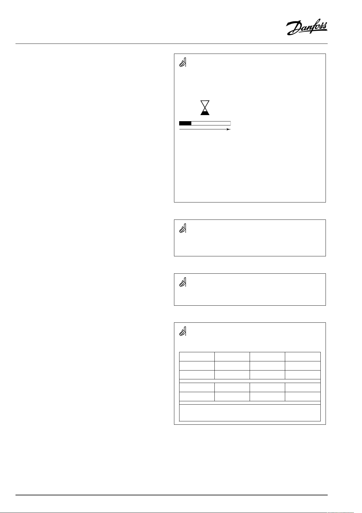
Automaticupdateofcontrollersoftware(firmware):
Thesoftwareofthecontrollerisupdatedautomaticallywhenthekey
isinserted(asofcontrollerversion1.11(ECL210/310)andversion
1.58(ECL296)).Thefollowinganimationwillbeshownwhenthe
softwareisbeingupdated:
Progressbar
Duringupdate:
•DonotremovetheKEY
Ifthekeyisremovedbeforethehour-glassisshown,youhave
tostartafresh.
•Donotdisconnectthepower
Ifthepowerisinterruptedwhenthehour-glassisshown,the
controllerwillnotwork.
•Manualupdateofcontrollersoftware(firmware):
Seethesection"Automatic/manualupdateoffirmware"
AsthisOperatingGuidecoversseveralsystemtypes,specialsystem
settingswillbemarkedwithasystemtype.Allsystemtypesareshown
inthechapter:'Identifyingyoursystemtype'.
°C(degreesCelsius)isameasuredtemperaturevaluewhereasK
(Kelvin)oftenisusedfortemperaturedifferences.
TheIDno.isuniquefortheselectedparameter .
ExampleFirstdigitSeconddigitLastthreedigits
1117411174
-
12174
IfanIDdescriptionismentionedmorethanonce,itmeansthatthere
arespecialsettingsforoneormoresystemtypes.Itwillbemarked
withthesystemtypeinquestion(e.g.12174-A266.9).
1
-
Circuit1Parameterno.
2
Circuit2Parameterno.
174
4|©Danfoss|2020.12
AQ356837161168en–010102
Page 5

OperatingGuideECLComfort310,applicationP318.21
ParametersindicatedwithanIDno.like"1x607"meanauniversal
parameter.
xstandsforcircuit/parametergroup.
DisposalNote
Thisproductshouldbedismantledanditscomponents
sorted,ifpossible,invariousgroupsbeforerecycling
ordisposal.
Alwaysfollowthelocaldisposalregulations.
AQ356837161168en–010102
©Danfoss|2020.12|5
Page 6
OperatingGuideECLComfort310,applicationP318.21
2.0Installation
2.1Beforeyoustart
Description,ingeneral
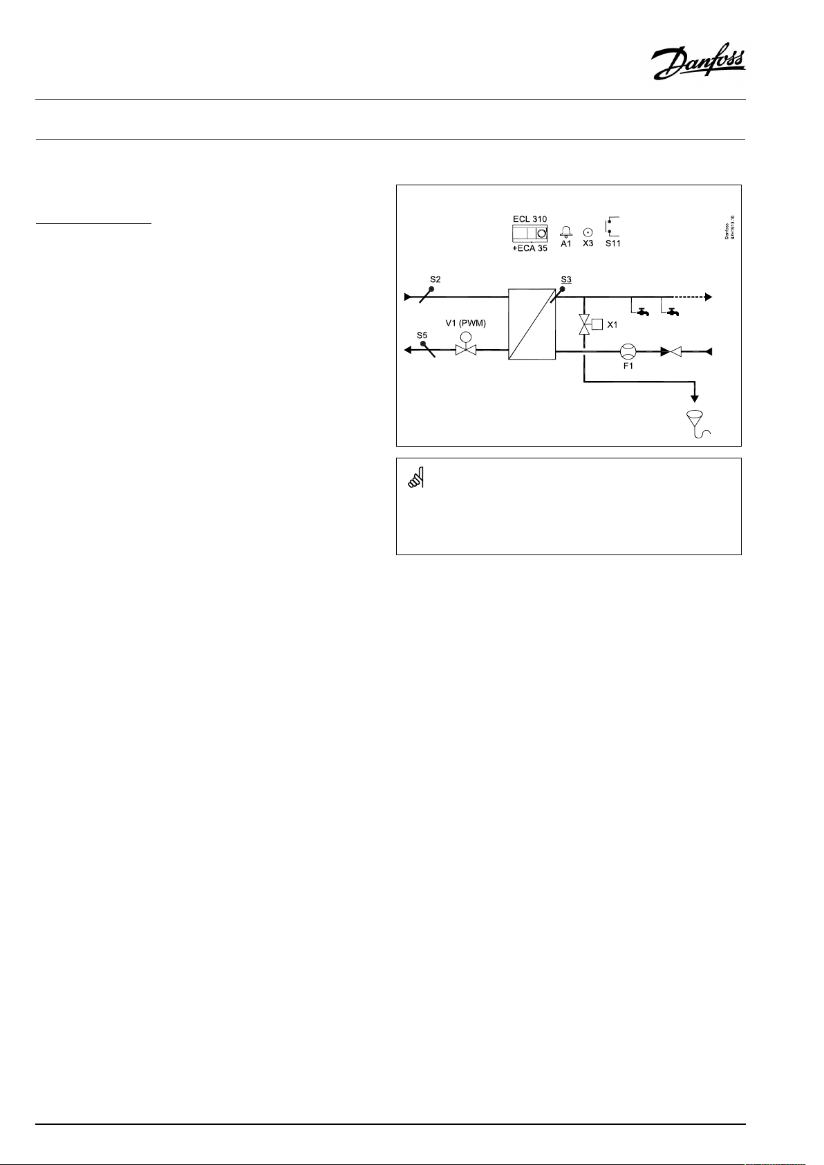
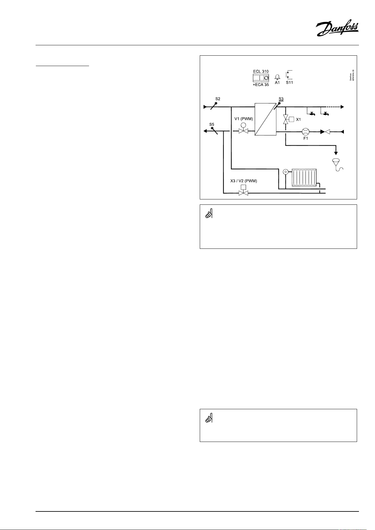
SubtypeP318.21ex.a
ControloftheflowtemperatureinanindirectlyheatedDHW
(DomesticHotWater)system.ThetemperaturesensorS3mustbe
connectedandthetemperaturecontrolis,amongothers,basedon
theflowsignalfromflowmeterF1.ThisflowispresentwhenDHW
istakenfromthetap.Thecontrolvalveisoperatedbyastepper
motorviatheV1output,whichisaPWMsignal.Withcontrolby
meansofasteppermotor(=quickoperating),thecontrolvalve
controlstheflowforcorrecttemperatureatS3.
ThemeasuredtemperatureatS2canchangetheXpvalue
(proportionalband)foroptimumDHWtemperaturecontrol.
ReturntemperatureS5isformonitoringonly.
ABypassfunctioncanmaintainadesiredtemperatureatS2.This
helpstoreducetheheat-uptimeforDHWifDHWhasnotbeen
takenfromthetapforalongertime.
BasedonthemeasuredtemperatureatS2,thecontrolvalve
V1canbeopenedperiodicallytoasetposition.ECLawaitsthe
temperaturetoreachasettemperatureandV1closesagain.A
schedule("Schedule,bypass")canbesetforhavingBypassactive
insetperiods.
Aflushfunction,activatinganON-OFFvalveviaoutputX1,can
avoidtheheatexchangertobetoowarmwhennoDHWistaken
fromthetap.
P318.21,ex.a:
Theshowndiagramisafundamentalandsimplifiedexampleanddoes
notcontainallcomponentsthatarenecessaryinasystem.
AllnamedcomponentsareconnectedtotheECLComfortcontroller .
Listofcomponents:
ECL310
ECA35
S2
S3
S5
S11
F1
V1
X1
X3
A1
ECLComfort310controller
Extensionmodule,placedinthebasepartof
ECL310
Supplytemperaturesensor(usedforBypass
functionandcompensatedXp)
(mandatory)DHWtemperaturesensor
Returntemperaturesensor(monitoringpurpose
only)
Input(potentialfree)forroomthermostat,
seeex.b
Flowsensor(connectedtoS7)
Actuator,PWMcontrolled,forcontrolvalve
ON-OFFflushvalve
Seeexampleb
Alarm
6|©Danfoss|2020.12
AQ356837161168en–010102
Page 7
OperatingGuideECLComfort310,applicationP318.21
SubtypeP318.21ex.b
Inadditiontothedescriptionofexamplea,thesubtypecan
furthermorecontrolaheatingcircuit.
TheON-OFFvalveX3(=solenoidvalve=magneticvalve)is
operatedbyeithertheX3outputortheV2output,whichisthe
PWMsignalforcontrolofasteppermotor.Inthiscasethestepper
motoreitherfullyopensorclosestheX3valve.
Theweekschedule("Schedule")determinestheperiods(Comfort)
wheretheheatingcircuitisswitchedin.
Aroomthermostat,potentialfree(=voltfree)connectedatinput
S11,canalsoswitchintheheatingif"Schedule"isinSavingmode.
Theheatingcircuitisswitchedoff(=closed)duringDHWheating.
P318.21,ex.b:
Theshowndiagramisafundamentalandsimplifiedexampleanddoes
notcontainallcomponentsthatarenecessaryinasystem.
AllnamedcomponentsareconnectedtotheECLComfortcontroller .
Listofcomponents:
ECL310
ECA35
ECLComfort310controller
Extensionmodule,placedinthebasepartof
ECL310
S2
Supplytemperaturesensor(usedforBypass
functionandcompensatedXp)
S3
S5
(mandatory)DHWtemperaturesensor
Returntemperaturesensor(monitoringpurpose
only)
S11
F1
V1
V2
X1
X3
A1
Input(potentialfree)forroomthermostat
Flowsensor(connectedtoS7)
Actuator,PWMcontrolled,forcontrolvalve
Actuator,PWMcontrolled,forheatingON-OFF
ON-OFFflushvalve
OutputforheatingON-OFF .AlternativetoV2
Alarm
Thecontrollerispre-programmedwithfactorysettingsthatareshown
inthe‘ParameterIDoverview’appendix.
AQ356837161168en–010102
©Danfoss|2020.12|7
Page 8
OperatingGuideECLComfort310,applicationP318.21
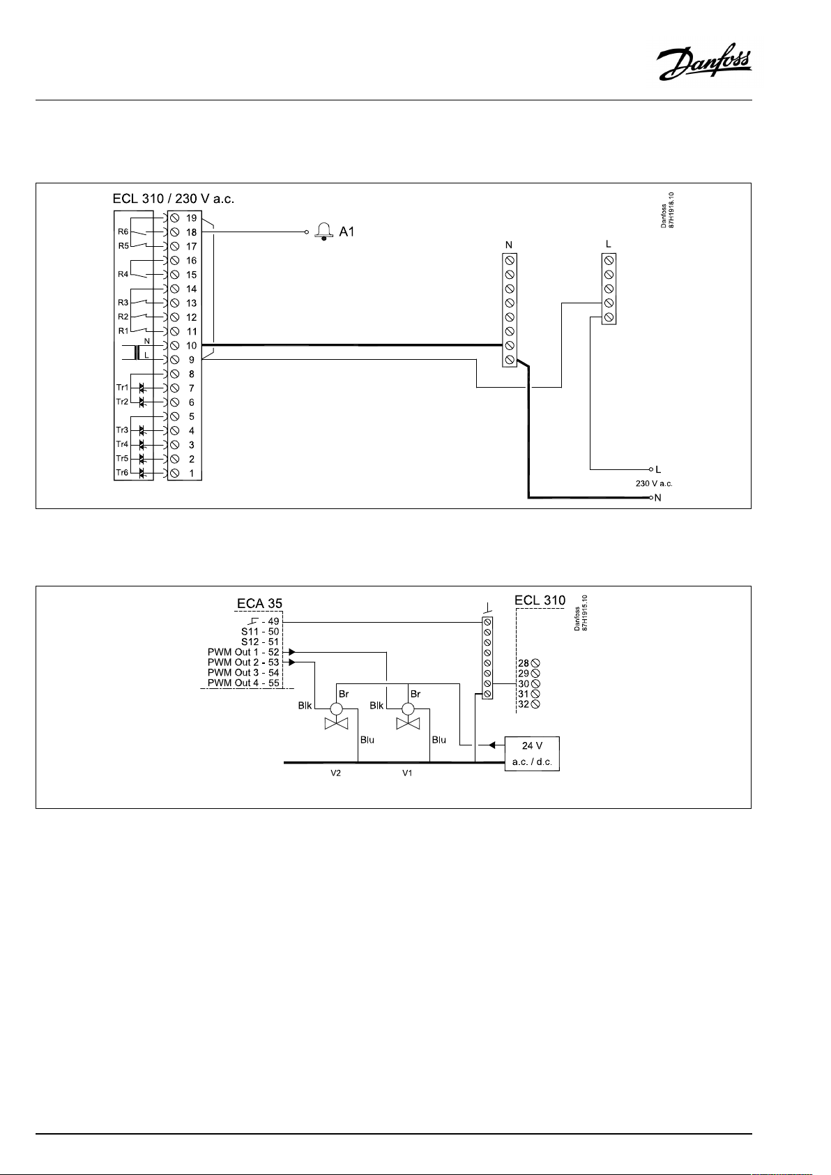
2.2Electricalconnections
ECL310,powersupplyandalarmconnections
ECA35,outputconnections
V1,V2
Blk=Black,Blu=Blue,Br=Brown
8|©Danfoss|2020.12
AQ356837161168en–010102
Page 9
OperatingGuideECLComfort310,applicationP318.21
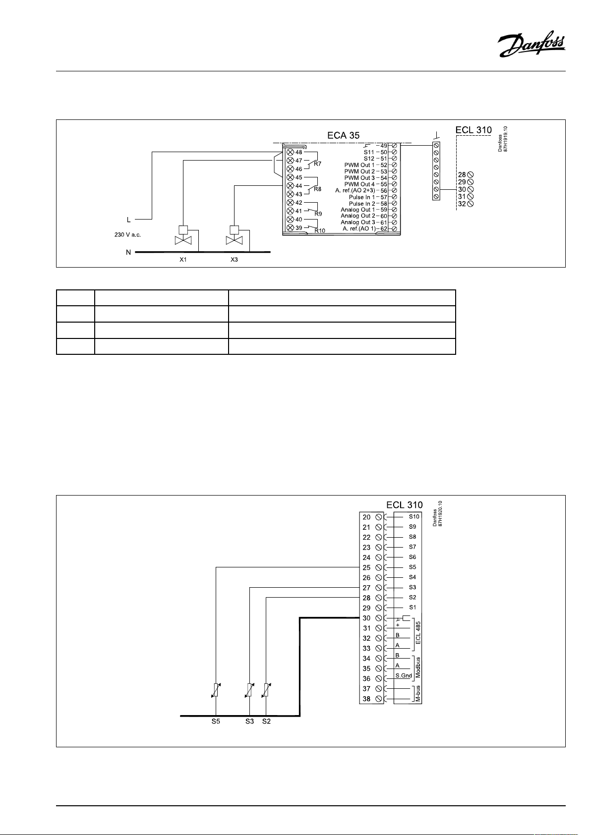
ECA35,outputconnections
X1,X3
Sensor
S2
S3
S5Returntemperaturesensor
*)
Theflowtemperaturesensormustalwaysbeconnectedinordertohavethedesiredfunctionality.
Ifthesensorisnotconnectedorthecableisshort-circuited,themotorizedcontrolvalvecloses(safetyfunction).
**)
ThesupplytemperaturesensormustbeconnectedforenablingtheBypassfunction.
ECL310,inputconnections
S2,S3,S5
Description
Supplytemperaturesensor**ESM-11,ESMB,ESMC,ESMU(allPt1000types)
Flowtemperaturesensor*
Recommendedtype
ESMU(Pt1000type)
ESM-11,ESMB,ESMC,ESMU(allPt1000types)
Note:S3mustbeconnected
AQ356837161168en–010102
©Danfoss|2020.12|9
Page 10
OperatingGuideECLComfort310,applicationP318.21
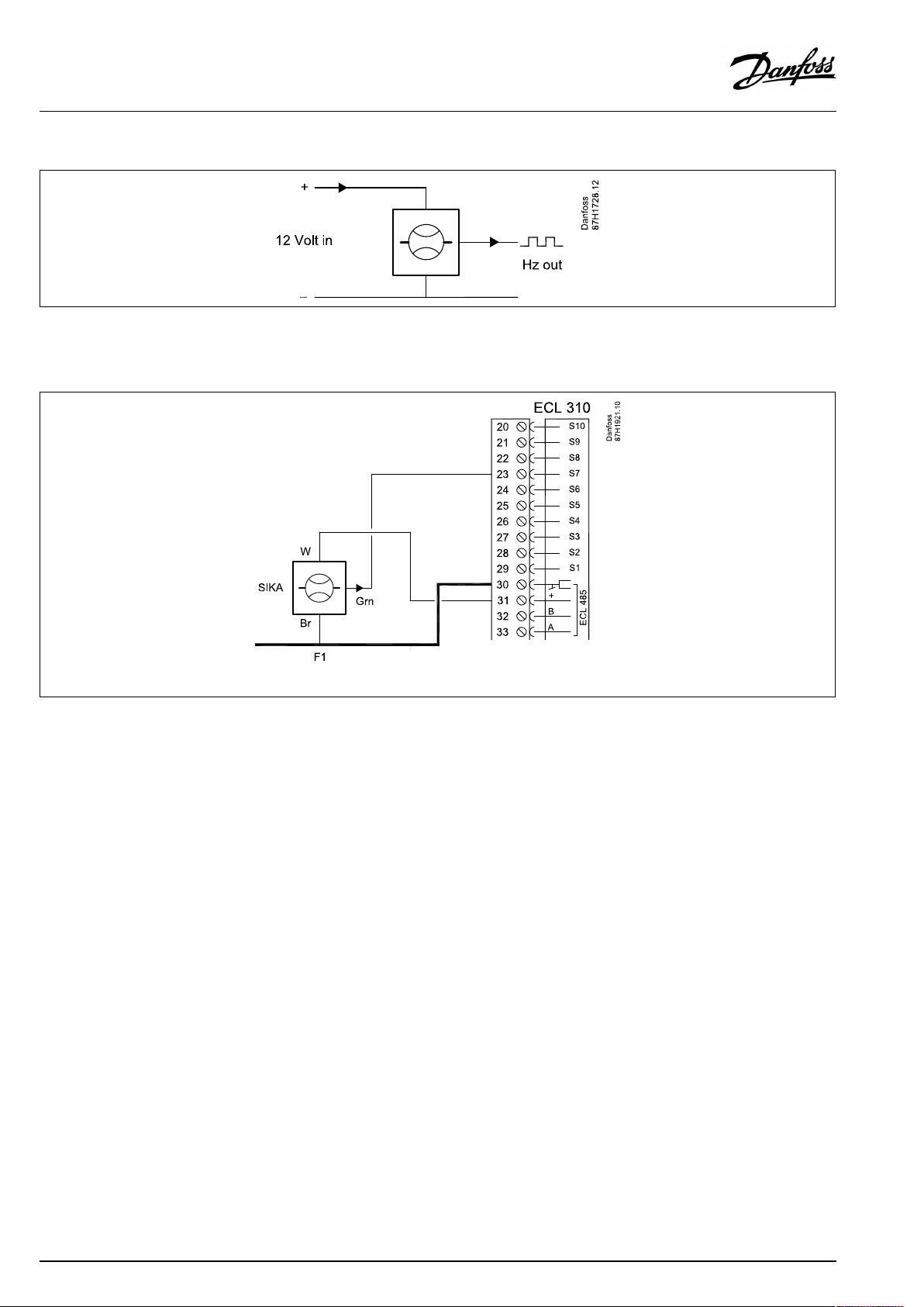
Flowsensor,F1
ECL310,inputconnections
FlowsensorconnectiontoS7
Br=Brown,Grn=Green,W=White
10|©Danfoss|2020.12
AQ356837161168en–010102
Page 11

OperatingGuideECLComfort310,applicationP318.21
ECA35,Inputconnections
S11
Inputconnections,ECA35
S11(Roomthermostat)
SeealsotheInstallationGuide(deliveredwiththeapplicationkey)
forapplicationspecificconnections.
SafetyNote
Necessaryassembly,start-up,andmaintenanceworkmustbe
performedbyqualifiedandauthorizedpersonnelonly.
Locallegislationsmustberespected.Thiscomprisesalsocablesize
andisolation(reinforcedtype).
AfusefortheECLComfortinstallationismax.10Atypically.
TheambienttemperaturerangefortheECLComfortinoperationis
0-55°C.Exceedingthistemperaturerangecanresultinmalfunctions.
Installationmustbeavoidedifthereisariskforcondensation(dew).
AQ356837161168en–010102
©Danfoss|2020.12|11
Page 12

OperatingGuideECLComfort310,applicationP318.21
3.0Dailyuse
3.1Understandingthecontrollerdisplay
Favoritedisplay1:
20.10.2020:
46.3:
16.51
50°C:
Favoritedisplay2:
V1:
X1:
V2:
X3:
54°C:
(--):
46°C:
(--):
Date
ActualDHWtemp.atS3
Actualtime
DesiredDHWtemp.
Openingin%ofV1
Flushactivity;shownOFF
HeatingvalveON-OFFcontrol
(0%=closed,100%=open)
HeatingvalveON-OFFcontrol;
shownON
Supplytemp.S2
Desiredbypasstemp.
DHWtemp.S3
(heatexchangertemp.)
DesiredDHWtemp.
40°C:
0.0l/h
Thedisplayisupdatedevery5thsecond.
WhenoperatingtheECLwiththedial,thedisplayis
immediatelyupdated.
Settingsandnavigationinmenus:
SeesectionsNavigationandSettings
Returntemp.S5
Actualwaterflow
Theindication(--)showsthatthe
relatedfunctionisnotactive.
12|©Danfoss|2020.12
AQ356837161168en–010102
Page 13

OperatingGuideECLComfort310,applicationP318.21
3.2Descriptionoffunctions
DHWtemperaturecontrol
DesiredDHWtemperatureissetintheFavoritedisplay1,
forexample50°C.
Thecold-waterflowsignalfromF1isusedtooptimizetheDHW
temperaturecontrol.
Thispro-activefunctionalitycompensatesforthedelaybeforethe
flowtemperaturesensorS3measuresachangeintemperature.
Bypassfunction
Forhavinganacceptabletemperature(supplytemperature)
presentattheinstallation,theBypassfunctionisusefulfor
minimizingtheDHWheat-uptime.
ThesupplytemperaturesensorS2isusedfortheBypassfunction.
AdesiredtemperaturefortheBypassfunctioncanbeset.
Furthermore,aweekschedule("Schedule,bypass")canbesetto
activatetheBypassinsetperiods.
(Navigation:MENU>Schedule,bypass)
Flushfunction
ThisfunctionisactiveonlyifnoDHWistakenfromthetap.
IfthetemperatureatS3getshigherthan"DHWmax.T" ,theFlush
isactivated(=X1opens)inperiods,setby"Delay" .
TheECLawaitstheS3temperaturetodrop,andFlushis
de-activatedwhentheS3temperatureis"DHWmax.diff"below
"DHWmax.T".
TheFlushfunctioncanbedisabledbysetting"DHWmax.T"toOFF .
Alarm
Analarmfunctionisonlyimplementedforsensorconnections.
SeetheP318OperatingGuidefordetails.
Flowsensor
SIKAVTY20flowsensorintheCWlinehasapulserateof119pulses
/liter.Theflowrangeis1...60l/min.Theflowsignal(pulses)is
senttotheECLforcontrollingtheDHWtemperatureatS3.
Steppermotorindicationsfromclosedtoopenposition
•redtriangle=fullyclosed(0%)
•redtriangle+bluerectangle
•bluerectangle
•bluerectangle+yellowcircle
•yellowcircle=fullyopened(100%)
Settingsfordailyuse
Normally,thesetvalueforDHWtemperatureissetonce.
AQ356837161168en–010102
©Danfoss|2020.12|13
Page 14

OperatingGuideECLComfort310,applicationP318.21
3.3Ageneraloverview:Whatdothesymbolsmean?
Symbol
Description
Outdoortemp.
Relativehumidityindoor
Roomtemp.
DHWtemp.
Positionindicator
Scheduledmode
Comfortmode
Savingmode
Frostprotectionmode
Manualmode
Standby
Coolingmode
Symbol
Temperature
Mode
Description
Alarm
Letter
Event
Monitoringtemperaturesensor
connection
Displayselector
Max.andmin.value
Trendinoutdoortemperature
Windspeedsensor
Sensornotconnectedornotused
Sensorconnectionshort-circuited
Fixedcomfortday(holiday)
Activeinfluence
Heatingactive(+)
Coolingactive(-)
Activeoutputoverride
Optimizedstartorstoptime
Heating
Cooling
DHW
Commoncontrollersettings
PumpON
PumpOFF
FanON
FanOFF
Actuatoropens
Actuatorcloses
Actuator,analoguecontrol
signal
Pump/fanspeed
DamperON
Circuit
Controlled
component
Numberofheatexchangers
Additionalsymbols,ECA30/31:
Symbol
InECA30/31onlythesymbolsthatarerelevanttotheapplicationin
thecontrolleraredisplayed.
Description
ECARemoteControlUnit
Connectionaddress(master:15,slaves:1-9)
15
Dayoff
Holiday
Relaxing(extendedcomfortperiod)
Goingout(extendedsavingperiod)
14|©Danfoss|2020.12
DamperOFF
AQ356837161168en–010102
Page 15

OperatingGuideECLComfort310,applicationP318.21
3.4Navigation,ECLApplicationKeyP318.21
Navigation(1)
Menu
Schedule
Schedule,bypass
Settings
InfluenceoverviewInfoifBypassisactive
WeekscheduleforHeatingcircuit
WeekscheduleforBypassfunction
AQ356837161168en–010102
©Danfoss|2020.12|15
Page 16

OperatingGuideECLComfort310,applicationP318.21
4.0Settingsoverview
Forfactorysettingsandsettingrange,seeappendix“ParameterIDoverview” .
ParametersindicatedwithanIDno.like"1x607"meanauniversalparameter.xstandsforcircuit/parametergroup.
Xpactual
"Emptyline”
BYPASS
Awaittime
Actual
DHWdeact.time
Delay
SupplyT(idle)
Pulse
Units
Voutmax.
Reverseout
Tn
Nz
Td
Wakeuplevel
Level
CWinfluence
Controldelay
SenddesiredT
DHWmax.T
DHWmax.diff.
SettingIDPage
1104518
1108018
1109720
11114
11115
1116519
11171
1118519
1118719
1119719
1133021
1135320
1135420
1136421
1150023
1158018
1158118
Factorysettingsincircuit(s)
1
19
20
20
21
22
22
22
20
16|©Danfoss|2020.12
AQ356837161168en–010102
Page 17

OperatingGuideECLComfort310,applicationP318.21
5.0Settings
5.1IntroductiontoSettings
Settings
Flowtemperature
Controlpar.1
Flowmeter
Application
Flushfunctionrelatedsettings
ParametersforDHWtemp.controlandBypassfunction
Parametersrelatedtoflowsensor
UsediftheECLisasub-controllerinanECLsystem
AQ356837161168en–010102
©Danfoss|2020.12|17
Page 18

OperatingGuideECLComfort310,applicationP318.21
5.2Flowtemperature
(Flushfunctionrelatedsettings)
MENU>Settings>Flowtemperature
DHWmax.T
SeeAppendix“ParameterIDoverview”
OFF:
Value:
Flushfunctionisdisabled
FlushfunctionisenabledifDHWtemp.atS3isabove
setvalue.
MENU>Settings>Flowtemperature
DHWmax.diff.
FlushfunctionisstoppedwhenDHWtemp.atS3getsbelow"DHWmax.T"
+setvalue.
SeeAppendix“ParameterIDoverview”
Example:
DHWmax.T=40°C,DHWmax.diff=-4K.
Result:FlushstopswhenDHWtemp.atS3getsbelow
36°C.
MENU>Settings>Flowtemperature
Delay
FlushstartsinintervalswithsetvaluewhenDHWtemp.atS3isabove"DHW
max.T"
11580
11581
11080
SeeAppendix“ParameterIDoverview”
MENU>Settings>Flowtemperature
DHWdeact.time
DHWdeactivationtime
SeeAppendix“ParameterIDoverview”
OFF:
Deactivationdisabled.
Flushingisaccordingto"DHWmax.diff."and"Delay" .
IftheDHWtemp.atS3doesnotgetbelow"DHW
max.T",flushisautomaticallystoppedafter100sec.
Value:
Flushingtime.DHWheatingisdeactivatedafterflush
hasstartedaccordingto"DHWmax.T"andsettime.
11045
18|©Danfoss|2020.12
AQ356837161168en–010102
Page 19

OperatingGuideECLComfort310,applicationP318.21
5.3Controlparameters(1)
MENU>Settings>Controlparameters(1)
Xpactual
Read-outoftheactualXp(proportionalband)basedonthesupply
temperatureS2.
SeeAppendix“ParameterIDoverview”
Xpisdeterminedbysettingsrelatedtothesupplytemperature.
Typically,thehigherthesupplytemperature,thehighertheXp
mustbetogetastabletemperaturecontrol.
ClickthemenuandseethescaleforXpat50and90°C.
Changesettingsifrequired.
IfthesupplytemperaturesensorS2isnotconnected,theXpvalue
isthevaluesetat50°C.
MENU>Settings>Controlparameters(1)
Tn
Integrationtime
11185
SeeAppendix“ParameterIDoverview”
Setahighintegrationtimeconstant(inseconds)toobtainaslow,
butstablereactiontotemperaturedeviations.
Alowintegrationtimeconstantwillmakethecontrollerreactfast,
butwithlessstability.
MENU>Settings>Controlparameters(1)
Td
Timederivative(Differentiationtime).
TheTdrelatedfunctioncanavoidatooaggressivereactioninthe
temperaturecontrol.
11197
SeeAppendix“ParameterIDoverview”
0:
Noinfluence
Lowvalueswillcauseminorinfluence,whereashigh
valueswillcausemajorinfluence.
MENU>Settings>Controlparameters(1)
Nz
Neutralzone.
SymmetricallytemperaturebandarounddesiredS3temperature.
WhentheS3temperatureisinsidetheNeutralzonetheregulationmakesno
changeoftheV1position.
SeeAppendix“ParameterIDoverview”
AQ356837161168en–010102
11187
©Danfoss|2020.12|19
Page 20

OperatingGuideECLComfort310,applicationP318.21
MENU>Settings>Controlparameters(1)
Voutmax.
Settingthemaximumopeningofthecontrolvalve.
SeeAppendix“ParameterIDoverview”
MENU>Settings>Controlparameters(1)
Reverseout
SeeAppendix“ParameterIDoverview”
NO:
Controlsignal(%)risesformoreopeningofthecontrol
valve.
YES:
Controlsignal(%)fallsformoreopeningofthecontrol
valve.
MENU>Settings>Controlparameters(1)
CWinfluence
Cold-Waterinfluence.
Thecold-waterflowsignalfromF1optimizestheDHWtemperaturecontrol.
Thevalueexpresseshowmany%of100liters/hourwilldoaninfluenceon
themotorizedcontrolvalve.
Lowvalueswillcauseminorinfluence,whereashighvalueswillcausemajor
influence.
11165
11171
11354
SeeAppendix“ParameterIDoverview”
MENU>Settings>Controlparameters(1)
Level
Changeinwaterflowmorethansetvaluewillmakefurtheractivationof
thecontrolvalve.
SeeAppendix“ParameterIDoverview”
MENU>Settings>Controlparameters(1)
"Emptyline”
MENU>Settings>Controlparameters(1)
BYPASS
(groupheadlineonly)
11353
20|©Danfoss|2020.12
AQ356837161168en–010102
Page 21

OperatingGuideECLComfort310,applicationP318.21
MENU>Settings>Controlparameters(1)
SupplyT(idle)
SeeAppendix“ParameterIDoverview”
OFF:
Bypassfunctionisdisabled.
Value:DesiredtemperaturetobemaintainedatS2.
MENU>Settings>Controlparameters(1)
Wakeuplevel
The%-valuereflectshowmuchV1opensthecontrolvalveatBypass.
Thecontrolvalvemustbeopenedproperlytoensureanacceptablewater
flowinthesupplypipe;readjustthesetting,ifneeded.
SeeAppendix“ParameterIDoverview”
MENU>Settings>Controlparameters(1)
Controldelay
SeeAppendix“ParameterIDoverview”
OFF:
V1opensthecontrolvalvewhenthetemperature
getsmorethan5Kbelow"SupplyT(idle)" .
V1closesthecontrolvalvewhenthetemperature
getsabove"SupplyT(idle)" .
ON:
Adaptiveadjustment.
Anadaptivefunctiondetectstheprogressofthe
supplytemperatureandmakeschangeoftheperiod
(Awaittime)betweentwoBypassactivities.
11097
11330
11364
MENU>Settings>Controlparameters(1)
Awaittime
Read-outvalue
Validonlywhen"Controldelay"issettoON.Itindicatesthenumberof
minutesthecontrolvalveisclosedbetweentwoBypass-basedopenings.
SeeAppendix“ParameterIDoverview”
Initialtimeatpower-upis15minutes.Iftimegetshigher,the
settingof"Wakeuplevel"shouldbeincreasedorthesettingof
"SupplyT(idle)"shouldbedecreased.
CalculatedAwaittimecannotberesetto15minuteswithout
re-poweringtheECL.
AQ356837161168en–010102
©Danfoss|2020.12|21
Page 22

OperatingGuideECLComfort310,applicationP318.21
5.4Flowmeter
MENU>Settings>Flowmeter
Actual
Read-outofactualflowintheColdWaterflowsensor.
Thevalueisbasedonappliedpulsesignalandthesettings"Pulse"and
"Units".
SeeAppendix“ParameterIDoverview”
MENU>Settings>Flowmeter
Pulse
Numberofpulsesfor1milli-literor1literofwaterflowthroughflowsensor
F1.
SeeAppendix“ParameterIDoverview”
MENU>Settings>Flowmeter
Units
SeeAppendix“ParameterIDoverview”
ml,l/h:
Numberofpulses("Pulse")representsoneml;
flowread-outinl/h
l,l/h:
Numberofpulses("Pulse")representsonel;
flowread-outinl/h
ml,m3/h:
Numberofpulses("Pulse")representsoneml;
flowread-outinm3/h
l,m3/h:
Numberofpulses("Pulse")representsonel;
read-outinm3/h
11114
11115
22|©Danfoss|2020.12
AQ356837161168en–010102
Page 23

OperatingGuideECLComfort310,applicationP318.21
5.5Application
MENU>Settings>Application
SenddesiredT
WhentheECLactsasaslavecontrollerinamaster/slavesystem,
informationaboutthedesiredflowtemperaturecanbesenttothemaster
controllerviatheECL485bus.
SeeAppendix“ParameterIDoverview”
OFF:
Informationaboutthedesiredflowtemperatureisnot
senttothemastercontroller.
ON:
Informationaboutthedesiredflowtemperatureissent
tothemastercontroller.
11500
AQ356837161168en–010102
©Danfoss|2020.12|23
Page 24

OperatingGuideECLComfort310,applicationP318.21
6.0Commoncontrollersettings
6.1Introductionto‘Commoncontrollersettings’
Navigationto"Commoncontrollersettings":
MENU(1)>Circuit1>Commoncontroller.
SeetheOperatingGuideforP318fordescriptioningeneral.
CommonController
Time&Date
Inputoverview
Log
Outputoverride
KeyfunctionsInfoaboutapplications.Copyfunctions
System
SettingTimeanddate
Actualvaluesfor:
DHWflowtemp.
Primaryreturntemp.
Supplytemp.
Logfeaturesfor:
DHWflowtemp.
Primaryreturntemp.
Supplytemp.
Overridepossibilityforselectedoutputs:
V1,X1,V2,X3,A1
Furthersystemrelatedinfoandcommunicationsettings
24|©Danfoss|2020.12
AQ356837161168en–010102
Page 25

OperatingGuideECLComfort310,applicationP318.21
7.0Appendix
7.1Applicationupload
Theapplicationuploadprocedureisthefollowingafterhaving
powereduptheECLComfortcontroller:
1.InserttheapplicationkeyP318
2.Selectlanguage.Info:Seesection7.4,Language
3.SelectsubtypeP318.21
4.SetTimeandDate
TheECLComfortcontrollerinstallstheapplication,initializesand
restarts.Outputrelaysareactivated/de-activated(click-sounds
fromthiscanbeheard).Thisalsomeansthat,forexample,Flush
andHeatingvalvecanbeswitchedONandOFFshortly.
AQ356837161168en–010102
©Danfoss|2020.12|25
Page 26

OperatingGuideECLComfort310,applicationP318.21
7.2Commissioning
WhentheP318.21applicationhasbeenuploadedtheECLComfort
controllerstartsinManualmode.Thiscanbeusedtoverifycorrect
connectionsoftemperatureandflowsensors.Alsoverifyingthe
controlledcomponents(valveactuators)forcorrectfunctionality
canbedone.
Theapplicationkeyisdeliveredwithfactorysettings.
Dependingonsystemtype,itmightbenecessarytochangesome
factorysettingsindividuallyinordertooptimizethefunctionality.
Theapplicationkeymustbeinsertedinordertochangesettings.
26|©Danfoss|2020.12
AQ356837161168en–010102
Page 27

OperatingGuideECLComfort310,applicationP318.21
7.3Powerdown/power-up
WhenthepowersupplytotheECLComfortcontrolleris
disconnected(powerdown),theoutputrelaysgotode-activated
position.
Thismeansthat,forexample,valveactuatorscanbeswitchedON.
SeetheelectricalconnectiondiagramsintheInstallationGuide.
Allrelaycontactsareshowninde-activatedsituation.Somerelay
contactsareclosed,somerelaycontactsareopen.
WhenthepowersupplytotheECLComfortcontrolleris
re-established(power-up),theoutputrelaysareactivated/
de-activated(click-soundsfromthiscanbeheard).Thisalsomeans
that,forexample,valveactuatorscanbeswitchedONandOFF
shortly.
AQ356837161168en–010102
©Danfoss|2020.12|27
Page 28

OperatingGuideECLComfort310,applicationP318.21
7.4Language
Language
Atapplicationupload,alanguagemustbeselected.*
IfanotherlanguagethanEnglishisselected,theselectedlanguage
ANDEnglishwillbeuploadedintotheECLcontroller.
ThismakesserviceeasyforEnglishspeakingservicepeople,just
becausetheEnglishlanguagemenuscanbevisiblebychanging
theactualsetlanguageintoEnglish.
(Navigation:MENU>Commoncontroller>System>Language)
Iftheuploadedlanguageisnotsuitable,theapplicationmustbe
erased.UserandSystemsettingscanbesavedontheapplication
keybeforeerasing.
Afternewuploadwithpreferredlanguage,theexistingUserand
Systemsettingscanbeuploaded.
*)
(ECLComfort310,24Volt)Iflanguagecannotbeselected,the
powersupplyisnota.c.(alternatingcurrent).
28|©Danfoss|2020.12
AQ356837161168en–010102
Page 29

OperatingGuideECLComfort310,applicationP318.21
7.5ParameterIDoverview
P318.x—xreferstothesubtypeslistedinthecolumn.
IDParameterNameP318.xSettingrangeFactoryUnitOwnsettings
11045DHWdeact.time21OFF ,1...250OFFSec
11080Delay212...20045Min
11097SupplyT(idle)21OFF ,10...100OFF°C
11114Pulse211...9999119
11115Units21
11165Voutmax.1,2,5,10,11,210...100100%
11171Reverseout1,2,5,10,11,21NO;YESNO
Xp215...25045/45K
11185Tn21OFF ,1...99910Sec
11187Nz10,11,210...91K
11197Td210.0...25.00.0Sec
11330Wakeuplevel210...1000%
11353Level210...25020l/h
11354
11364Control,delay21
11500SenddesiredT1,2,5,10,11,21
11580DHWmax.T21OFF,10...11040°C
11581
CWinfluence
DHWmax.diff.
21
21-20...-1
ml,l/h;l,l/h;ml,
m3/h;l,m3/hl,l/h
OFF,0.1...100.0
OFF;ONON
OFF;ONON
7.0%
-4
K
AQ356837161168en–010102
©Danfoss|2020.12|29
Page 30

OperatingGuideECLComfort310,applicationP318.21
Installer:
By:
Date:
30|©Danfoss|2020.12
AQ356837161168en–010102
Page 31

OperatingGuideECLComfort310,applicationP318.21
*087H9333*
AQ356837161168en–010102
2020.12|©Danfoss|31
 Loading...