

Page 1
OperatingGuide
ECLComfort310,applicationP318
1.0TableofContents
1.0TableofContents...............................................1
1.1Importantsafetyandproductinformation.....................2
2.0Installation........................................................6
2.1Beforeyoustart.....................................................6
2.2Identifyingthesystemtype......................................29
2.3Mounting...........................................................30
2.4Placingthetemperaturesensors................................34
2.5Electricalconnections.............................................36
2.6InsertingtheECLApplicationKey..............................44
2.7Checklist............................................................50
2.8Navigation,ECLApplicationKeyA318.........................51
3.0Dailyuse.........................................................67
3.1Howtonavigate...................................................67
3.2Understandingthecontrollerdisplay..........................68
3.3Ageneraloverview:Whatdothesymbolsmean?...........69
3.4Monitoringtemperaturesandsystem
components........................................................70
3.5Influenceoverview................................................71
3.6Manualcontrol.....................................................72
3.7Schedule............................................................73
7.0Commoncontrollersettings............................114
7.1Introductionto‘Commoncontrollersettings’..............114
7.2Time&Date.......................................................115
7.3Inputoverview...................................................116
7.4Log.................................................................117
7.5Outputoverride..................................................118
7.6Keyfunctions.....................................................119
7.7System.............................................................121
8.0Miscellaneous................................................128
8.1ECA30/31setupprocedures.................................128
8.2Overridefunction................................................136
8.3Severalcontrollersinthesamesystem......................139
8.4Frequentlyaskedquestions....................................142
8.5Definitions........................................................144
8.6Type(ID6001),overview.......................................148
8.7Automatic/manualupdateoffirmware.....................149
8.8ParameterIDoverview..........................................150
4.0Settingsoverview............................................74
5.0Settings...........................................................76
5.1IntroductiontoSettings..........................................76
5.2Tanktemperature..................................................77
5.3X3control...........................................................81
5.4Flowtemperature..................................................82
5.5Returnlimit.........................................................84
5.6Controlparameters................................................88
5.7Flowmeter..........................................................97
5.8Application.........................................................99
5.9Anti-bacteria......................................................101
6.0Event.............................................................103
6.1IntroductiontoEvent...........................................103
6.2ChargeT...........................................................104
6.3DHWflowT.......................................................106
6.4Tanktemperature................................................108
6.5SupplyT...........................................................110
6.6Anti-bacteria......................................................111
6.7Tsensordefect...................................................112
6.8Eventoverview...................................................113
©Danfoss|2018.09VI.JM.Q5.02|1
Page 2

OperatingGuideECLComfort310,applicationP318
1.1Importantsafetyandproductinformation
1.1.1Importantsafetyandproductinformation
ThisOperatingGuideisassociatedwiththeECLApplicationKey
P318(codeno.087H3835).
TheECLApplicationKeyP318forDomesticHotWater(DHW)
temperaturecontrolcontains4subtypes:
•P318.1,bufferbasedtemperaturecontrol
•P318.2,bufferandmixingbasedtemperaturecontrol
•P318.10,advancedtemperaturecontrol
•P318.11,temperaturecontrolledflowsystemwithlayercontrol
andbuffercharging
SeetheInstallationGuideforapplicationdiagramsandelectrical
connections.
Theapplicationdiagramsshowmandatorytemperaturesensors
withanunderscore;exampleS3.
ThedescribedfunctionsarerealizedinECLComfort310whichalso
allowsM-bus,ModbusandEthernet(Internet)communication.
TheApplicationKeyP318complieswithECLComfort310
controllersasoffirmwareversion1.11.Thefirmware(controller
software)isvisibleatstart-upofthecontrollerandin'Common
controllersettings'in'System'.
UptotwoRemoteControlUnits,ECA30orECA31,canbe
connected.
TheapplicationP318workswithadditionalInternalI/Omodules:
•TheextensionmoduleECA32gives0-10Voltsignalforspeed
controlofcontrolpump,chargingpumpandcirculationpump.
•TheextensionmoduleECA35gives0-10Voltsignalforspeed
controlofcontrolpump,chargingpumpandcirculationpump.
ECA35canalsogivePWM*signalforspeedcontrolofthe
abovelistedpumptypes.
Apumpcanalsobeconsideredasacirculator.
TheECLComfort310workswitheitheroneECA32oroneECA
35.TheInternalI/Omoduleinquestionisplacedinthebasepart
oftheECLComfort310.
*PWM=PulseWidthModulation
TogetherwiththeECLComfort310theadditionalInternalI/O
modulescanalsobeusedforextradatacommunicationtoSCADA:
•Temperature,Pt1000(default)
•0-10voltsignals
•Digitalinput
Theset-upofinputtypecanbedonebymeansoftheDanfoss
Software"ECLTool".
Navigation:Danfoss.com>Products&Solutions>Products>
DistrictHeatingandCooling>Documentation>Tools&Software
>ECLTool.
TheURLis:https://www.danfoss.com/en/service-and-
support/downloads
ECLComfort310isavailableas:
•ECLComfort310,230volta.c.(codeno.087H3040)
•ECLComfort310B,230volta.c.(codeno.087H3050)
•ECLComfort310,24volta.c.(codeno.087H3044)
TheB-typehasnodisplayanddial.
2|©Danfoss|2018.09
VI.JM.Q5.02
Page 3
OperatingGuideECLComfort310,applicationP318
TheB-typeisoperatedbymeansoftheremotecontrolunit
ECA30/31:
•ECA30(codeno.087H3200)
•ECA31(codeno.087H3201)
InternalI/Omodules:
•ECA32(codeno.087H3202)
•ECA35(codeno.087H3205)
BasepartforECLComfort310,230voltand24volt:Codeno.
087H3230.
AdditionaldocumentationforECLComfort210and310,modules
andaccessoriesisavailableonhttp://heating.danfoss.com/.
Applicationkeysmightbereleasedbeforealldisplaytextsare
translated.InthiscasethetextisinEnglish.
SafetyNote
Toavoidinjuryofpersonsanddamagestothedevice,itisabsolutely
necessarytoreadandobservetheseinstructionscarefully.
Necessaryassembly,start-up,andmaintenanceworkmustbe
performedbyqualifiedandauthorizedpersonnelonly.
Locallegislationsmustberespected.Thiscomprisesalsocable
dimensionsandtypeofisolation(doubleisolatedat230V).
AfusefortheECLComfortinstallationismax.10Atypically.
TheambienttemperaturerangesforECLComfortinoperationare:
ECLComfort210/310:0-55°C
ECLComfort296:0-45°C.
Exceedingthetemperaturerangecanresultinmalfunctions.
Installationmustbeavoidedifthereisariskforcondensation(dew).
Thewarningsignisusedtoemphasizespecialconditionsthatshould
betakenintoconsideration.
Thissymbolindicatesthatthisparticularpieceofinformationshould
bereadwithspecialattention.
VI.JM.Q5.02
©Danfoss|2018.09|3
Page 4
OperatingGuideECLComfort310,applicationP318
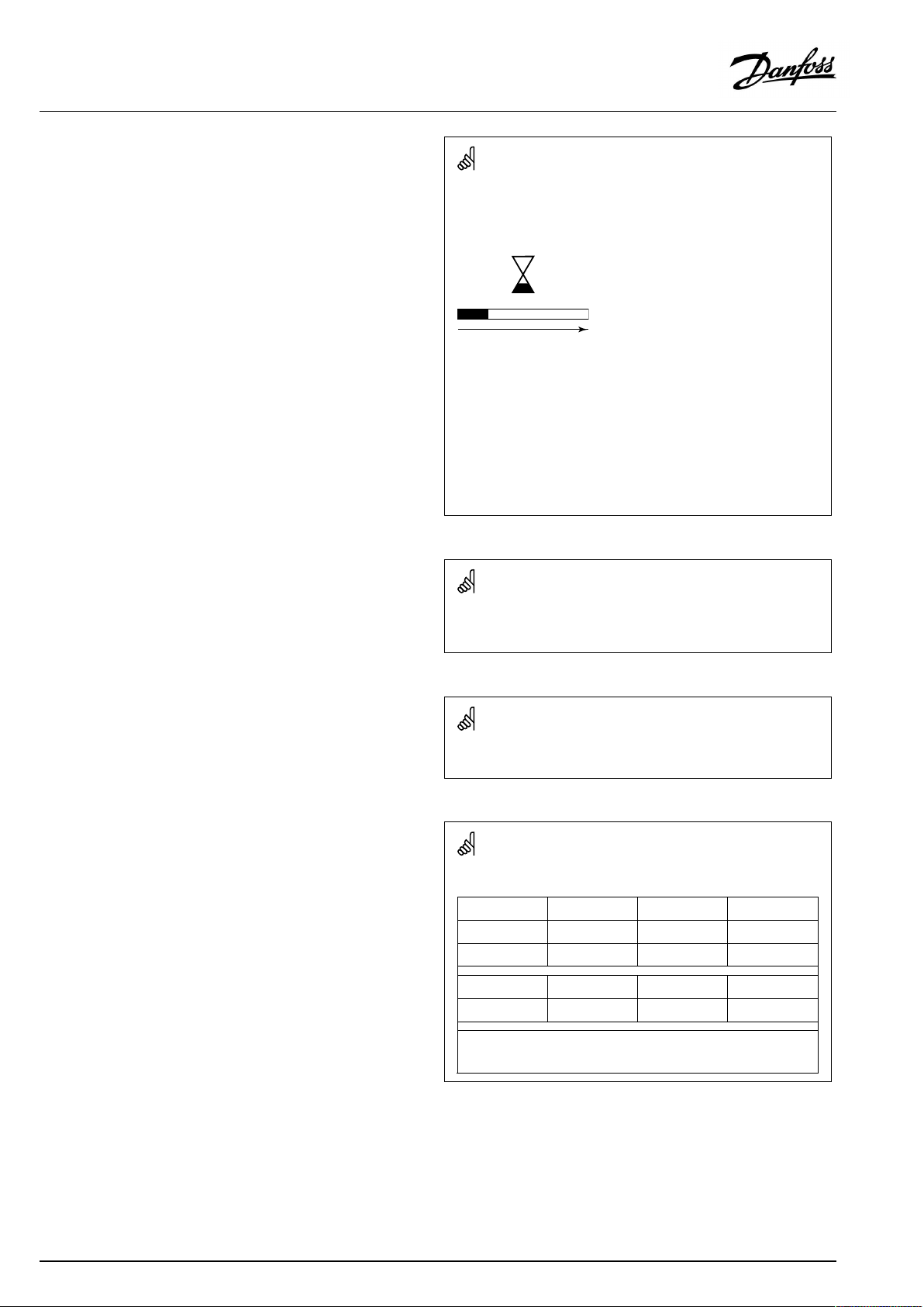
Automaticupdateofcontrollersoftware(firmware):
Thesoftwareofthecontrollerisupdatedautomaticallywhenthekey
isinserted(asofcontrollerversion1.11(ECL210/310)andversion
1.58(ECL296)).Thefollowinganimationwillbeshownwhenthe
softwareisbeingupdated:
Progressbar
Duringupdate:
•DonotremovetheKEY
Ifthekeyisremovedbeforethehour-glassisshown,youhave
tostartafresh.
•Donotdisconnectthepower
Ifthepowerisinterruptedwhenthehour-glassisshown,the
controllerwillnotwork.
•Manualupdateofcontrollersoftware(firmware):
Seethesection"Automatic/manualupdateoffirmware"
AsthisOperatingGuidecoversseveralsystemtypes,specialsystem
settingswillbemarkedwithasystemtype.Allsystemtypesareshown
inthechapter:'Identifyingyoursystemtype'.
°C(degreesCelsius)isameasuredtemperaturevaluewhereasK
(Kelvin)oftenisusedfortemperaturedifferences.
TheIDno.isuniquefortheselectedparameter.
ExampleFirstdigitSeconddigitLastthreedigits
1117411174
-
12174
IfanIDdescriptionismentionedmorethanonce,itmeansthatthere
arespecialsettingsforoneormoresystemtypes.Itwillbemarked
withthesystemtypeinquestion(e.g.12174-A266.9).
1
-
Circuit1Parameterno.
2
Circuit2Parameterno.
174
4|©Danfoss|2018.09
VI.JM.Q5.02
Page 5

OperatingGuideECLComfort310,applicationP318
ParametersindicatedwithanIDno.like"1x607"meanauniversal
parameter.
xstandsforcircuit/parametergroup.
DisposalNote
Thisproductshouldbedismantledanditscomponents
sorted,ifpossible,invariousgroupsbeforerecycling
ordisposal.
Alwaysfollowthelocaldisposalregulations.
VI.JM.Q5.02
©Danfoss|2018.09|5
Page 6
OperatingGuideECLComfort310,applicationP318
2.0Installation
2.1Beforeyoustart
TheECLapplicationkeyP318contains4subtypes,P318.1,P318.2,
P318.10andP318.11.
ThebasicprinciplesforapplicationP318.1:
TemperaturecontrolofDHWbuffer
ThedesiredDHWtemperatureatS6(setincircuit1,favorite
display1)determinesthebufferchargingprocedure.Thebuffer
temperaturesensorsS6andS8,thesupplytemperaturesensorS2
andthechargingtemperaturesensorS3arethemostimportant
sensorsandmustbeconnected.Ifoneofthementioned
temperaturesensorsisnotconnected,thecontrolvalveM1will
close;alternatively,thecontrolpumpP1/V1willstop.
ThechargingtemperatureatS3isbasedonthedesiredDHW
temperatureatS6andasetchargingdifference.
TheapplicationallowsinternalorexternalDHWcirculation.When
connectedforexternalcirculation,thedesiredS3temperatureis
thesameasthedesiredDHWtemperature,whenchargingisnot
inprogress.
Optional:TemperaturecontrolofthecirculationpipeatS9ensures
thedesiredtemperaturebymeansofON/OFFcontrolofpump
P3orspeedcontrolofpumpV3.Duringthechargingprocessthe
circulationpumpcanbeswitchedOFForrunataminimumspeed.
Startbufferchargingprocess:
1.BuffertemperatureS6temperaturegetslowerthan('Desired
DHWtemperature'+'Startdifference').
Anexample:60°C+(-5)=55°C
2.X1isswitchedON
3.M1openseitherfullyortoapresetposition(alternatively,P1/
V1isswitchedON/presetspeed)inordertoincreasethesupply
temperatureS2.Returntemperaturelimitationisrespected.
4.P2/V2isswitchedONwhensupplytemperatureS2getshigher
than('DesiredDHWtemperature'+'Pumpstartdiff.').
Anexample:60°C+3K=63°C
V2startswithminimumspeed,forexample20%.
5.M1(orP1/V1)controlsthechargingtemperatureatS3.
6.V2increasesthespeedaslongasthechargingtemperatureS3
ishigherthan(desiredchargingtemperature-2K).
Stopbufferchargingprocess:
1.BuffertemperatureS6temperaturegetshigherthan(2K+
'DesiredDHWtemperature'+'Startdifference)
AND
LowerbuffertemperatureS8getshigherthan('DesiredDHW
temperature'+'Stopdifference).
Anexample:S6temperaturehigherthan(2+60°C+(-5)=
57°C)AND(60°C+(-8)=52°C)
2.P2isswitchedOFF ,respecting'Char.Ppost-run'.V2changes
to0%.
NOTE:Post-runisnotrespectedifchargingtemperatureS3islower
thandesiredchargingtemperature.
3.X1isswitchedOFF.
4.M1closes(alternatively,P1/V1stops)ormaintainsthedesired
temperatureatS3.
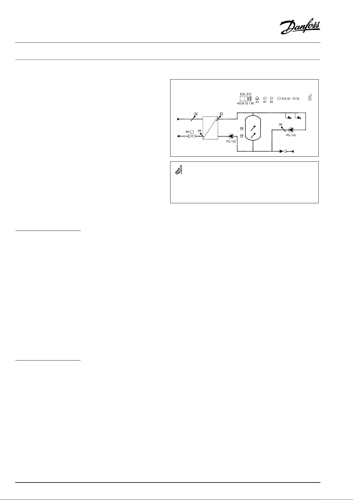
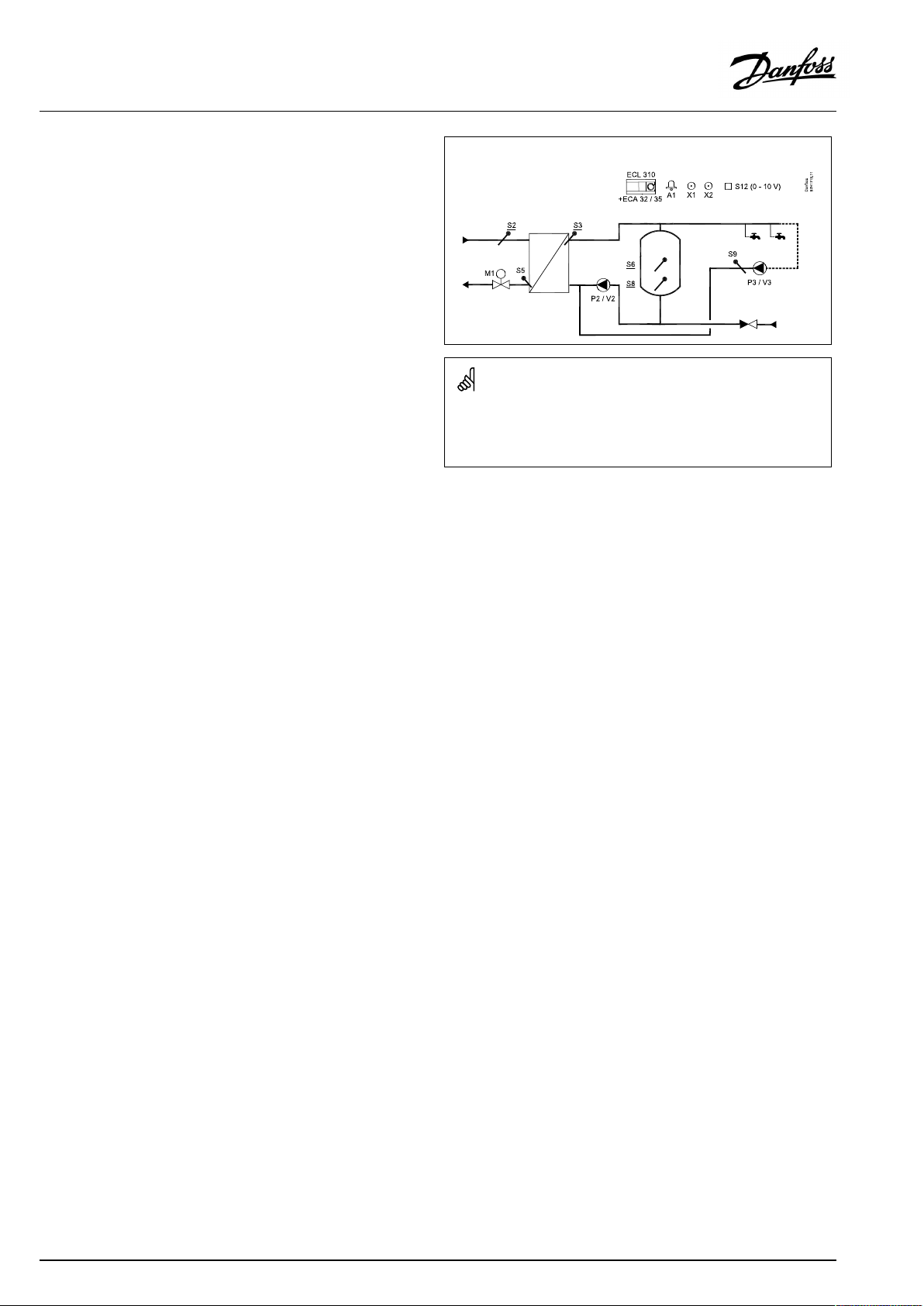
P318.1,ex.a,applicationwithcontrolvalveandinternalDHWcirculation:
Theshowndiagramisafundamentalandsimplifiedexampleanddoes
notcontainallcomponentsthatarenecessaryinasystem.
AllnamedcomponentsareconnectedtotheECLComfortcontroller.
Listofcomponents:
ECL310
ECA32
ECA35
S2
S3
S5Returntemperaturesensor
S6
S8
S9
S12
P2
V2
P3
V3
M1
X1
X2
A1
ECLComfort310controller
Built-inextensionmodule,0-10Voutputs
Built-inextensionmodule,0-10Voutputsand
PWMoutputs
(mandatory)Supplytemperaturesensor
(mandatory)Chargingtemperaturesensor
(mandatory)Buffertemperaturesensor
(mandatory)Lowerbuffertemperaturesensor
DHWcirculationreturntemperaturesensor
0-10VinputfordesiredtemperatureatS6
Chargingpump(ON-OFFcontrolled)
Speedcontrolofchargingpump(0-10VorPWM)
Circulationpump(ON-OFFcontrolled)
Speedcontrolofcirculationpump(0-10Vor
PWM)
Motorizedcontrolvalve(3-pointcontrolled)
Heatdemandsignal
Anti-bacteriafunctionisactive
Alarm
6|©Danfoss|2018.09
VI.JM.Q5.02
Page 7

OperatingGuideECLComfort310,applicationP318
Bymeansofaweekschedule,theDHWcirculationcanbeON/
OFFcontrolled.
ThemotorizedcontrolvalveM1isopenedgraduallywhen
thechargingtemperatureislowerthanthedesiredcharging
temperatureandviceversa.
Alternatively,thecontrolpumpP1/V1isincreasedinspeedwhen
thechargingtemperatureislowerthanthedesiredcharging
temperatureandviceversa.
ThereturntemperatureS5canbelimited,forexamplenottobe
toohigh.Ifso,thedesiredchargingtemperatureatS3canbe
adjusted(typicallytoalowervalue);thisresultsinagradualclosing
ofthemotorizedcontrolvalveor,alternatively,alowerspeedof
thecontrolpump.
DHWcirculationtemperaturecontrol:
IfDHWcirculationreturntemperaturesensorS9isnotconnected,
theON-OFFcontrolledpumpwillbeON.Aspeedcontrolledpump
canbelimitedtoadesiredspeedbymeansofV.outmax.and
V.outminsettings.
TheON-OFFoutputX1isONatDHWheatingdemand.
Asanoption,thedesiredDHWtemperatureatS6canbeset
externally.Avoltagesignal(1-10Volt)canbeappliedtoinputS12
(ECA32/35).Thescaleforvoltageversustemperaturecanbeset.
Ananti-bacteriafunctionfortheDHWbufferisavailablefor
activationonselecteddaysoftheweek.
Theanti-bacteriafunctioncanbesettoincludetheDHW
circulation.
TheON-OFFoutputX2isONatactiveanti-bacteriafunction.
VI.JM.Q5.02
©Danfoss|2018.09|7
Page 8
OperatingGuideECLComfort310,applicationP318
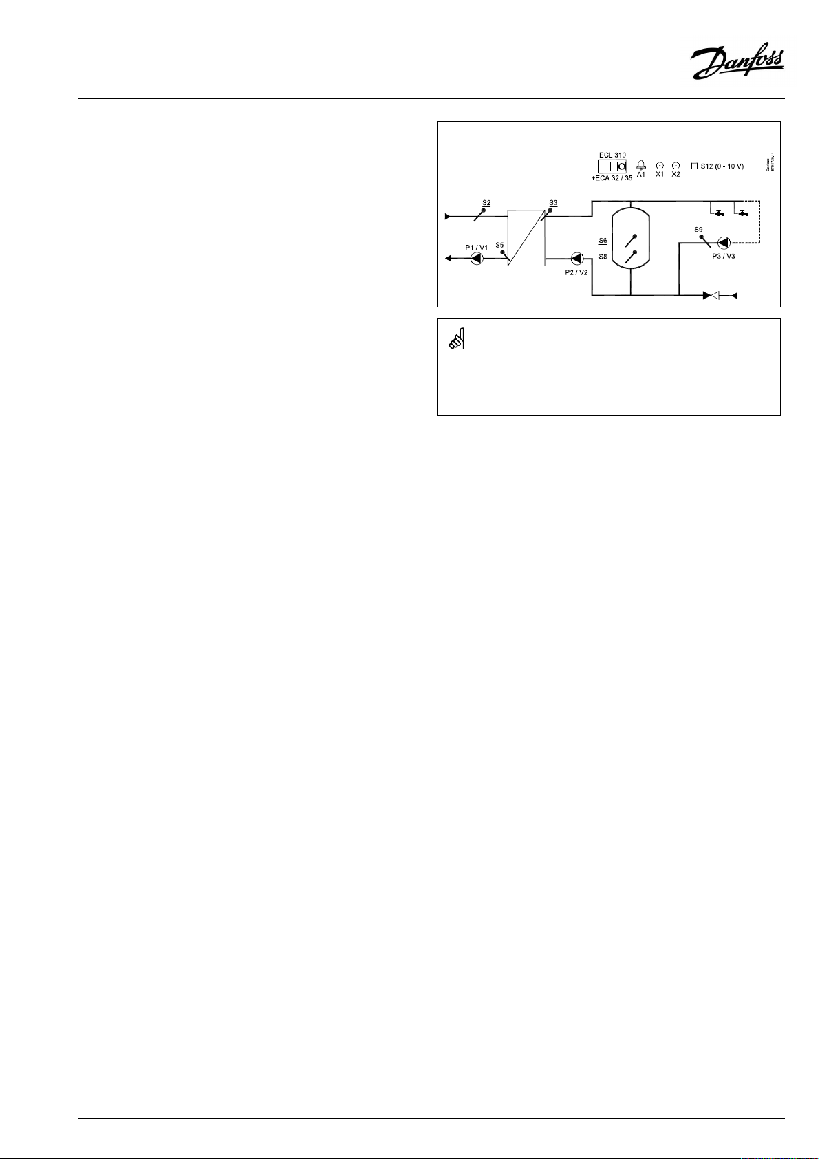
P318.1,ex.b,applicationwithcontrolvalveandexternalDHWcirculation:
Theshowndiagramisafundamentalandsimplifiedexampleanddoes
notcontainallcomponentsthatarenecessaryinasystem.
AllnamedcomponentsareconnectedtotheECLComfortcontroller.
Listofcomponents:
ECL310
ECA32
ECA35
ECLComfort310controller
Built-inextensionmodule,0-10Voutputs
Built-inextensionmodule,0-10Voutputsand
PWMoutputs
S2
S3
(mandatory)Supplytemperaturesensor
(mandatory)Chargingtemperaturesensor
S5Returntemperaturesensor
S6
S8
S9
S12
P2
V2
P3
V3
(mandatory)Buffertemperaturesensor
(mandatory)Lowerbuffertemperaturesensor
DHWcirculationreturntemperaturesensor
0-10VinputfordesiredtemperatureatS6
Chargingpump(ON-OFFcontrolled)
Speedcontrolofchargingpump(0-10VorPWM)
Circulationpump(ON-OFFcontrolled)
Speedcontrolofcirculationpump(0-10Vor
PWM)
M1
X1
X2
A1
Motorizedcontrolvalve(3-pointcontrolled)
Heatdemandsignal
Anti-bacteriafunctionisactive
Alarm
8|©Danfoss|2018.09
VI.JM.Q5.02
Page 9
OperatingGuideECLComfort310,applicationP318
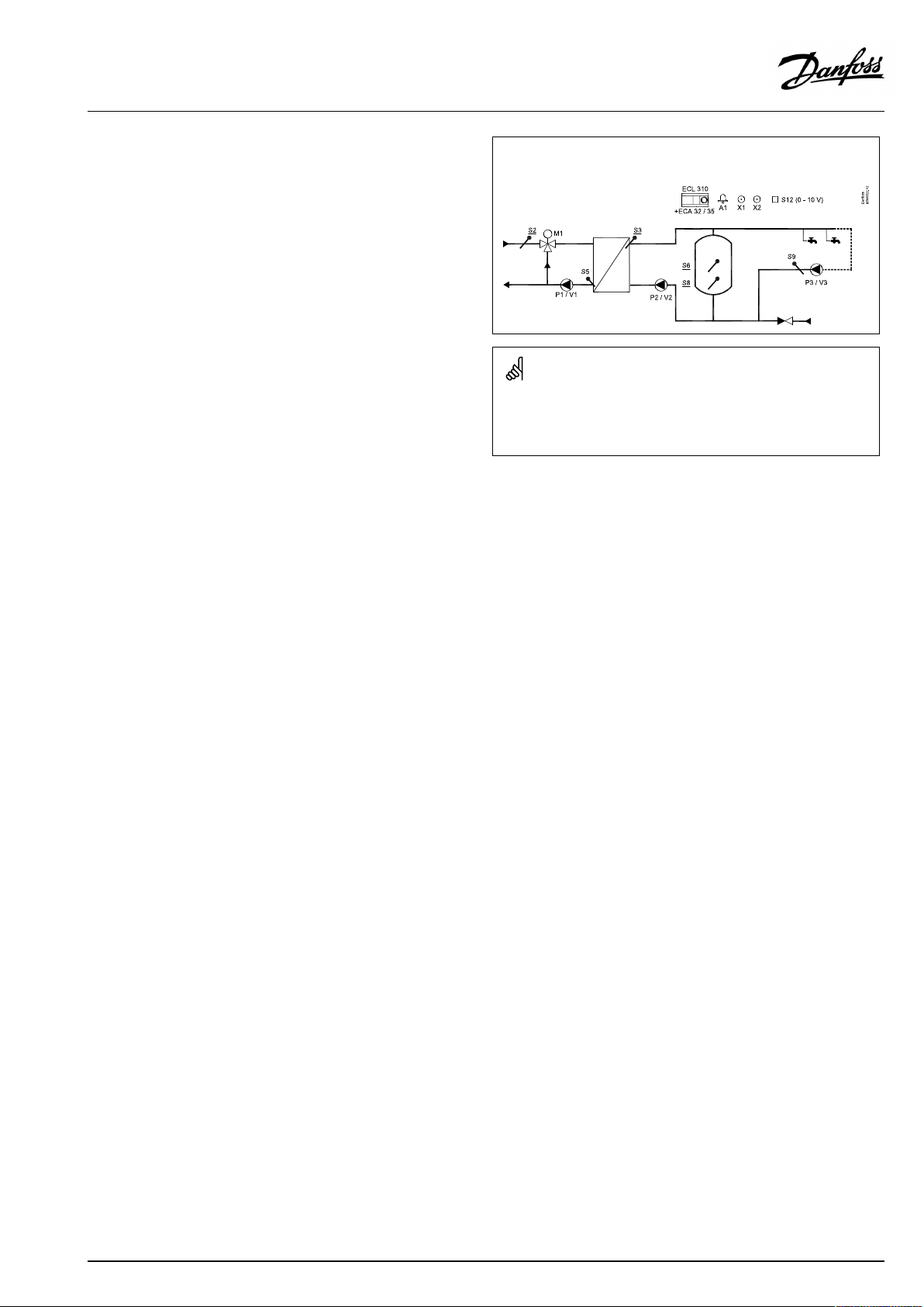
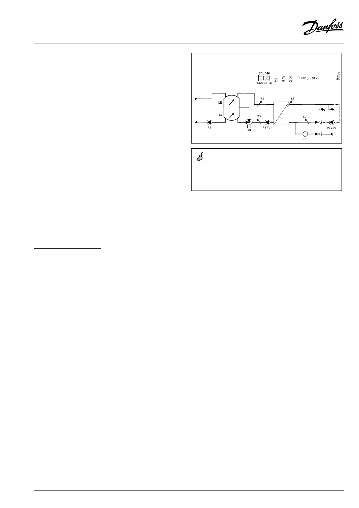
P318.1,ex.c,applicationwithcontrolpumpandinternalDHWcirculation:
Theshowndiagramisafundamentalandsimplifiedexampleanddoes
notcontainallcomponentsthatarenecessaryinasystem.
AllnamedcomponentsareconnectedtotheECLComfortcontroller.
Listofcomponents:
ECL310
ECA32
ECA35
ECLComfort310controller
Built-inextensionmodule,0-10Voutputs
Built-inextensionmodule,0-10Voutputsand
PWMoutputs
S2
S3
(mandatory)Supplytemperaturesensor
(mandatory)Chargingtemperaturesensor
S5Returntemperaturesensor
S6
S8
S9
S12
P1
V1
P2
V2
P3
V3
(mandatory)Buffertemperaturesensor
(mandatory)Lowerbuffertemperaturesensor
DHWcirculationreturntemperaturesensor
0-10VinputfordesiredtemperatureatS6
Controlpump(ON-OFFcontrolled)
Speedcontrolofcontrolpump(0–10VorPWM)
Chargingpump(ON-OFFcontrolled)
Speedcontrolofchargingpump(0-10VorPWM)
Circulationpump(ON-OFFcontrolled)
Speedcontrolofcirculationpump(0-10Vor
PWM)
X1
X2
A1
Heatdemandsignal
Anti-bacteriafunctionisactive
Alarm
VI.JM.Q5.02
©Danfoss|2018.09|9
Page 10

OperatingGuideECLComfort310,applicationP318
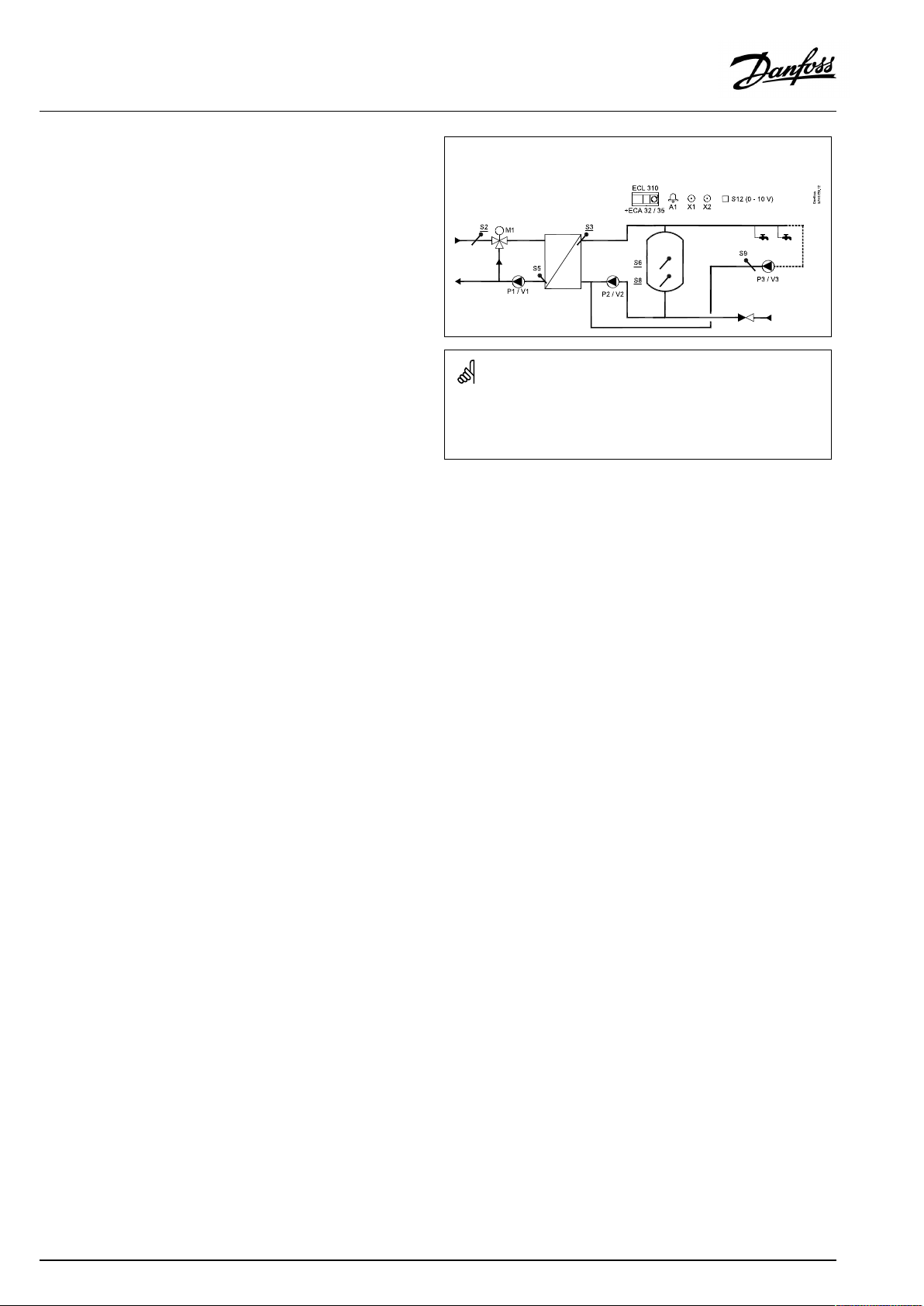
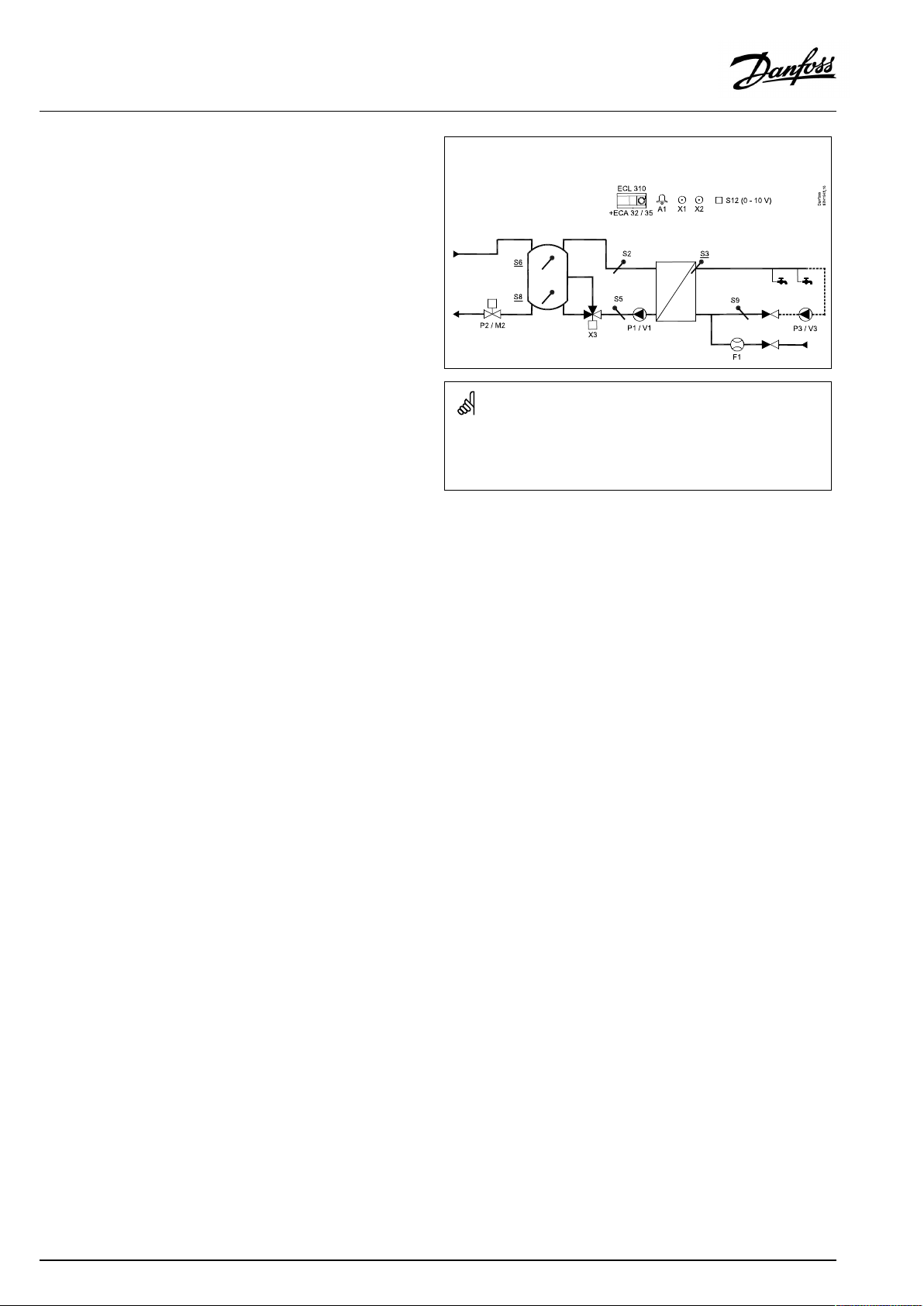
P318.1,ex.d,applicationwithcontrolpumpandexternalDHWcirculation:
Theshowndiagramisafundamentalandsimplifiedexampleanddoes
notcontainallcomponentsthatarenecessaryinasystem.
AllnamedcomponentsareconnectedtotheECLComfortcontroller.
Listofcomponents:
ECL310
ECA32
ECA35
ECLComfort310controller
Built-inextensionmodule,0-10Voutputs
Built-inextensionmodule,0-10Voutputsand
PWMoutputs
S2
S3
(mandatory)Supplytemperaturesensor
(mandatory)Chargingtemperaturesensor
S5Returntemperaturesensor
S6
S8
S9
S12
P1
V1
P2
V2
P3
V3
(mandatory)Buffertemperaturesensor
(mandatory)Lowerbuffertemperaturesensor
DHWcirculationreturntemperaturesensor
0-10VinputfordesiredtemperatureatS6
Controlpump(ON-OFFcontrolled)
Speedcontrolofcontrolpump(0–10VorPWM)
Chargingpump(ON-OFFcontrolled)
Speedcontrolofchargingpump(0-10VorPWM)
Circulationpump(ON-OFFcontrolled)
Speedcontrolofcirculationpump(0-10Vor
PWM)
X1
X2
A1
Heatdemandsignal
Anti-bacteriafunctionisactive
Alarm
10|©Danfoss|2018.09
VI.JM.Q5.02
Page 11
OperatingGuideECLComfort310,applicationP318
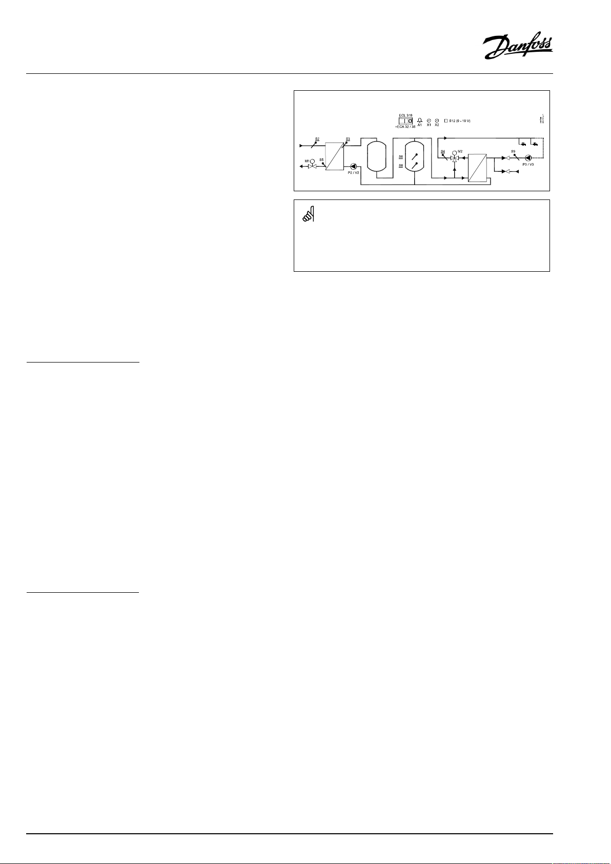
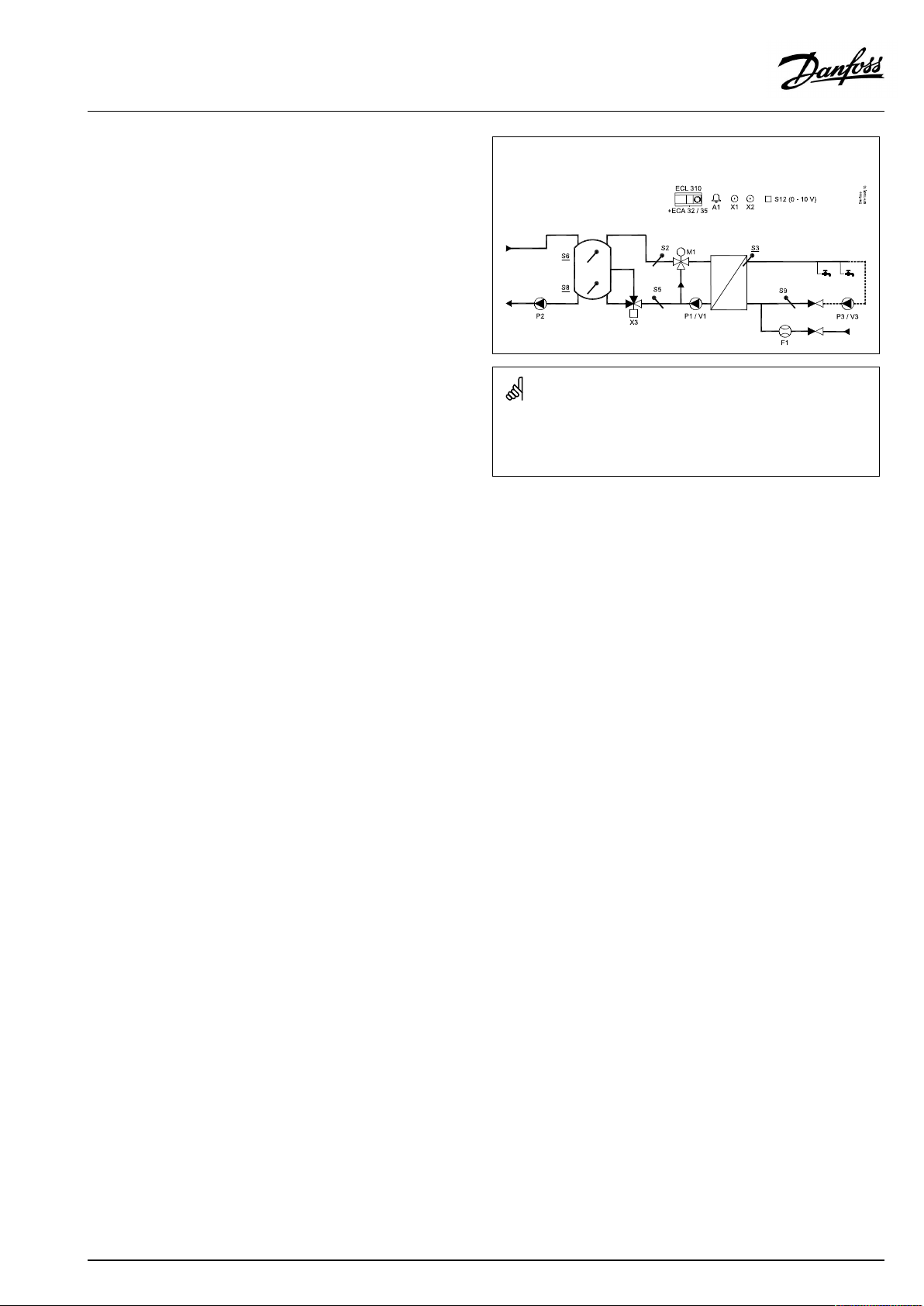
P318.1,ex.e:Primarysideisacombinationofa3-portcontrolvalveanda
controlpump.InternalDHWcirculation:
Theshowndiagramisafundamentalandsimplifiedexampleanddoes
notcontainallcomponentsthatarenecessaryinasystem.
AllnamedcomponentsareconnectedtotheECLComfortcontroller.
Listofcomponents:
ECL310
ECA32
ECA35
ECLComfort310controller
Built-inextensionmodule,0-10Voutputs
Built-inextensionmodule,0-10Voutputsand
PWMoutputs
S2
S3
(mandatory)Supplytemperaturesensor
(mandatory)Chargingtemperaturesensor
S5Returntemperaturesensor
S6
S8
S9
S12
M1
P1
V1
P2
V2
P3
V3
(mandatory)Buffertemperaturesensor
(mandatory)Lowerbuffertemperaturesensor
DHWcirculationreturntemperaturesensor
0-10VinputfordesiredtemperatureatS6
Motorized3-portcontrolvalve(3-pointcontrolled)
Controlpump(ON-OFFcontrolled)
Speedcontrolofcontrolpump(0–10VorPWM)
Chargingpump(ON-OFFcontrolled)
Speedcontrolofchargingpump(0-10VorPWM)
Circulationpump(ON-OFFcontrolled)
Speedcontrolofcirculationpump(0-10Vor
PWM)
X1
X2
A1
Heatdemandsignal
Anti-bacteriafunctionisactive
Alarm
VI.JM.Q5.02
©Danfoss|2018.09|11
Page 12
OperatingGuideECLComfort310,applicationP318
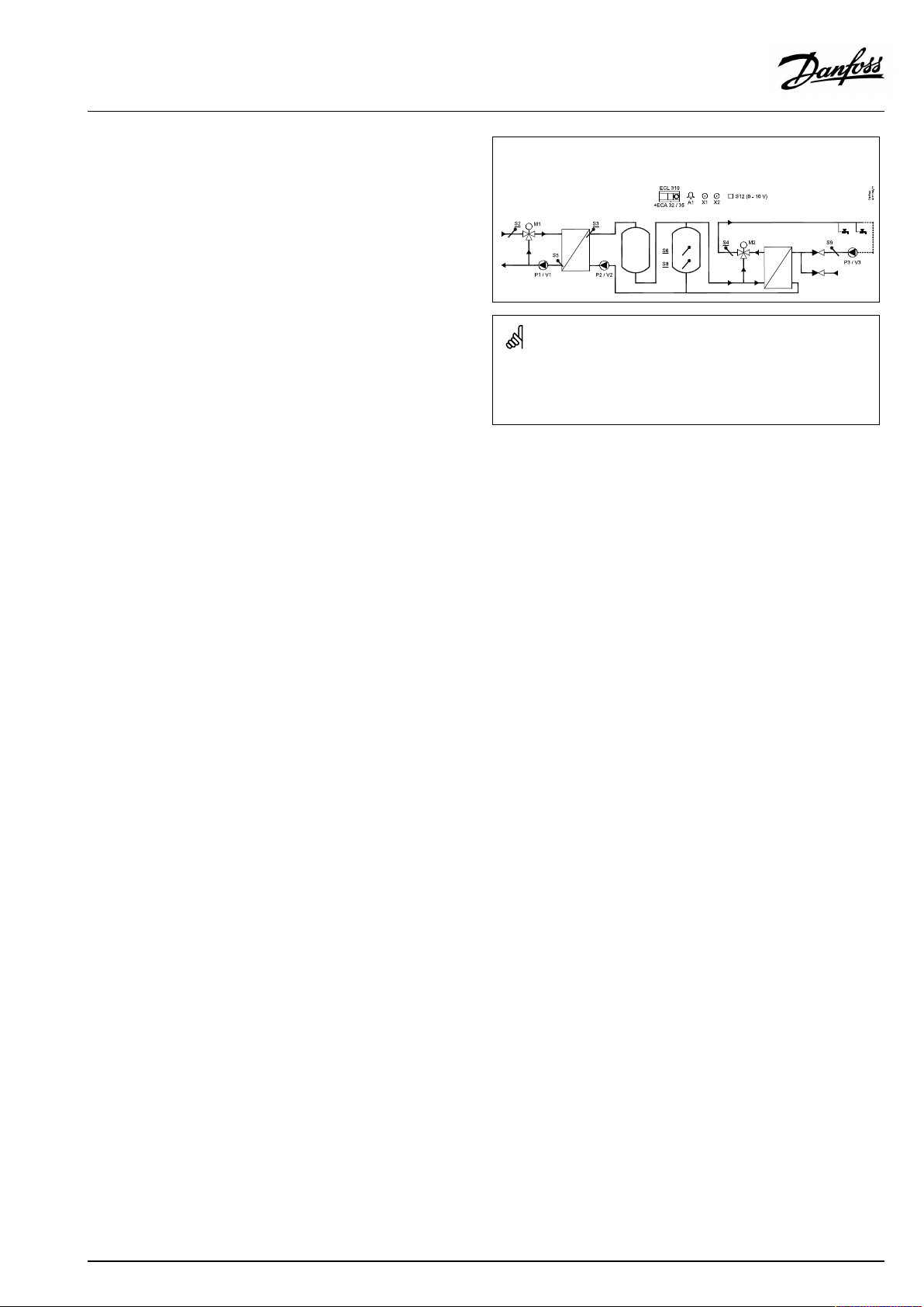
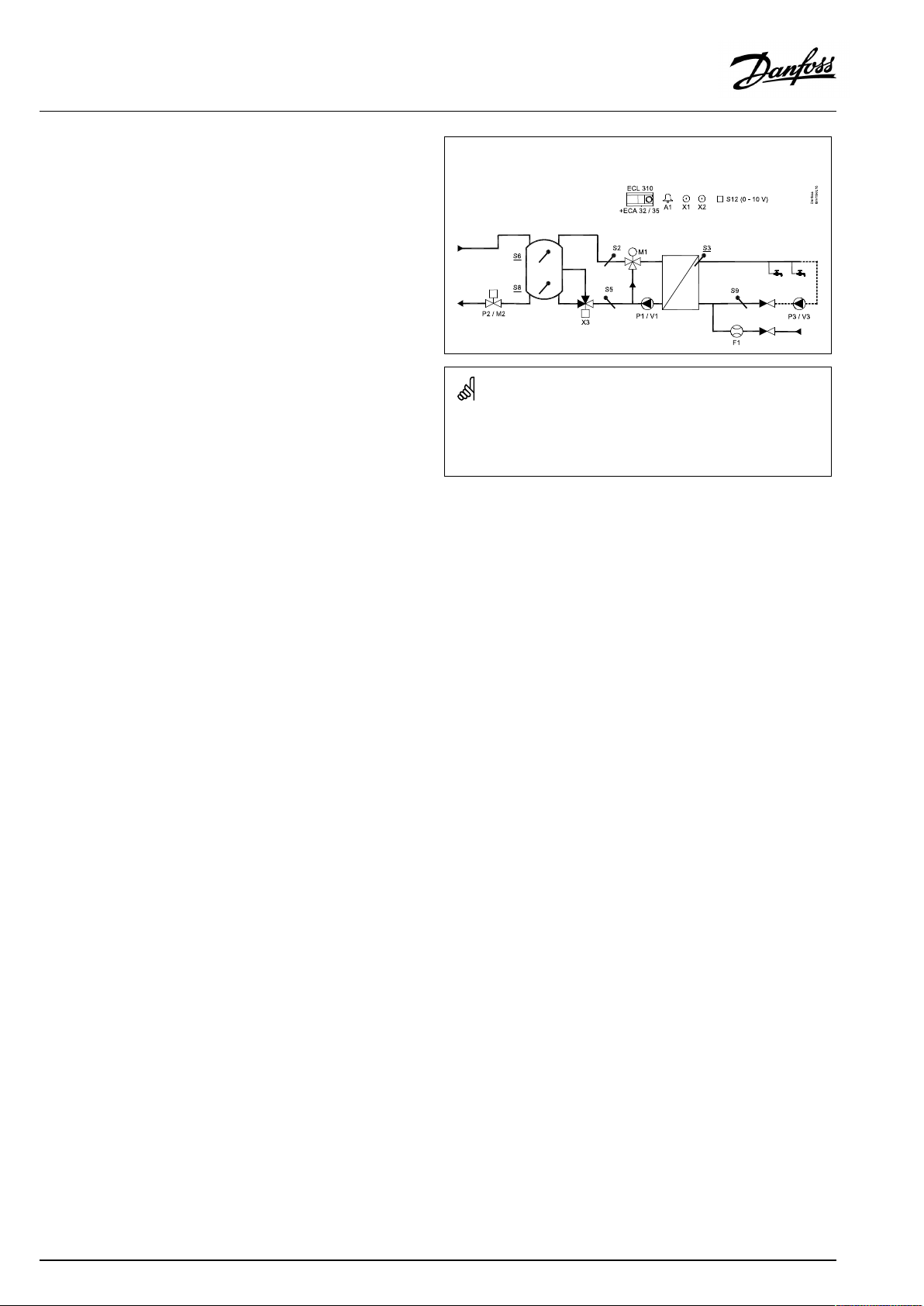
P318.1,ex.f:Primarysideisacombinationofa3-portcontrolvalveanda
controlpump.ExternalDHWcirculation:
Theshowndiagramisafundamentalandsimplifiedexampleanddoes
notcontainallcomponentsthatarenecessaryinasystem.
AllnamedcomponentsareconnectedtotheECLComfortcontroller.
Listofcomponents:
ECL310
ECA32
ECA35
ECLComfort310controller
Built-inextensionmodule,0-10Voutputs
Built-inextensionmodule,0-10Voutputsand
PWMoutputs
S2
S3
(mandatory)Supplytemperaturesensor
(mandatory)Chargingtemperaturesensor
S5Returntemperaturesensor
S6
S8
S9
S12
M1
P1
V1
P2
V2
P3
V3
(mandatory)Buffertemperaturesensor
(mandatory)Lowerbuffertemperaturesensor
DHWcirculationreturntemperaturesensor
0-10VinputfordesiredtemperatureatS6
Motorized3-portcontrolvalve(3-pointcontrolled)
Controlpump(ON-OFFcontrolled)
Speedcontrolofcontrolpump(0–10VorPWM)
Chargingpump(ON-OFFcontrolled)
Speedcontrolofchargingpump(0-10VorPWM)
Circulationpump(ON-OFFcontrolled)
Speedcontrolofcirculationpump(0-10Vor
PWM)
X1
X2
A1
Heatdemandsignal
Anti-bacteriafunctionisactive
Alarm
12|©Danfoss|2018.09
VI.JM.Q5.02
Page 13

OperatingGuideECLComfort310,applicationP318
Recommendations/consideringsettings:
Int./Ext.DHWcirc.
"Cont.Tcontrol"(11054)*
P318.1,ex.a
P318.1,ex.b
P318.1,ex.c
P318.1,ex.d
P318.1,ex.e
P318.1,ex.f
*)
Circuit1>MENU>Settings>Application>
**)
Circuit1>MENU>Settings>Controlparameters1>
***)
Circuit1>MENU>Settings>Controlparameters1>
OFF
ON
OFF
ON
OFF
ON
Speed,P1/V1
"Voutmax. "/"Voutmin. "
(11165/11167)**
Max./min.tosamevalue
"Adapttime"(11065)*:OFF
Max./min.tosamevalue
"Adapttime"(11065)*:OFF
Actuatorrunningtime
"Mrun"(11186)***
X
X
X
X
VI.JM.Q5.02
©Danfoss|2018.09|13
Page 14
OperatingGuideECLComfort310,applicationP318
ThebasicprinciplesforapplicationP318.2:
DHWtemperatureandbuffercontrol
IfthemeasuredDHWtemperatureS4islowerthanthedesired
DHWtemperature(setincircuit1,favoritedisplay1),themotorized
controlvalveM2opensgraduallyformorewaterfromthebuffer
tank.
Coldtapwateris,viatheheat-exchanger,usedtocontroltheDHW
temperatureS4ifthetemperaturegetshigherandwillgradually
closethecontrolvalveM2.
TheDHWtemperaturesensorS4,thechargingtemperaturesensor
S3,thesupplytemperaturesensorS2andthebuffertemperature
sensorsS6andS8arethemostimportantsensorsandmustbe
connected.Ifoneofthementionedtemperaturesensorsisnot
connected,thecontrolvalveM1willclose;alternatively,thecontrol
pumpP1/V1willstop.
ThebufferchargingtemperatureatS3isbasedonthesetdesired
buffertemperatureatS6(setincircuit2,favoritedisplay1).
Optional:TemperaturecontrolofthecirculationpipeatS9ensures
thedesiredtemperaturebymeansofON/OFFcontrolofpump
P3orspeedcontrolofpumpV3.
Startbufferchargingprocess:
1.BuffertemperatureS6temperaturegetslowerthan('Desired
chargingtemperature'+'Startdifference').
Anexample:70°C+(-5)=65°C
2.X1isswitchedON
3.M1opens(alternatively,P1/V1isswitchedON/presetspeed)
inordertoincreasethesupplytemperature
S2.Returntemperaturelimitationisrespected.
4.P2/V2isswitchedONwhensupplytemperatureS2getshigher
than('Desiredchargingtemperature'+'Pumpstartdiff. ').
Anexample:70°C+3K=73°C
V2startswithminimumspeed,forexample20%.
5.M1(orP1/V1)controlsthechargingtemperatureatS3.
6.V2increasesthespeedaslongasthechargingtemperatureS3
ishigherthan(desiredchargingtemperature-2K).
Stopbufferchargingprocess:
1.BuffertemperatureS6temperaturegetshigherthan(2K+
'Desiredchargingtemperature'+'Startdifference)
AND
LowerbuffertemperatureS8getshigherthan('DesiredDHW
temperature'+'Stopdifference).
Anexample:S6temperaturehigherthan(2+70°C+(-5)=
67°C)
ANDS8temperaturehigherthan(70°C+(-8)=62°C).
2.P2isswitchedOFF ,respecting'DHWPpost-run' .V2changes
to0%.
NOTE:Post-runisnotrespectedifchargingtemperatureS3islower
thandesiredchargingtemperature.
3.X1isswitchedOFF.
4.M1closes(alternatively,P1/V1stops).
P318.2,ex.a,applicationwithcontrolvalveforbuffertemperaturecontrol:
Theshowndiagramisafundamentalandsimplifiedexampleanddoes
notcontainallcomponentsthatarenecessaryinasystem.
AllnamedcomponentsareconnectedtotheECLComfortcontroller.
Listofcomponents:
ECL310
ECA32
ECA35
ECLComfort310controller
Built-inextensionmodule,0-10Voutputs
Built-inextensionmodule,0-10Voutputsand
PWMoutputs
S2
S3
S4
(mandatory)Supplytemperaturesensor
(mandatory)Chargingtemperaturesensor
(mandatory)DHWtemperaturesensor
S5Returntemperaturesensor
S6
S8
S9
S12
P2
V2
P3
V3
(mandatory)Buffertemperaturesensor
(mandatory)Lowerbuffertemperaturesensor
DHWcirculationreturntemperaturesensor
0-10VinputfordesiredtemperatureatS6
Chargingpump(ON-OFFcontrolled)
Speedcontrolofchargingpump(0-10VorPWM)
Circulationpump(ON-OFFcontrolled)
Speedcontrolofcirculationpump(0-10Vor
PWM)
M1
M2
X1
X2
A1
Motorizedcontrolvalve(3-pointcontrolled)
Motorizedcontrolvalve(3-pointcontrolled)
Bufferheatingdemandsignal
Anti-bacteriafunctionisactive
Alarm
14|©Danfoss|2018.09
VI.JM.Q5.02
Page 15

OperatingGuideECLComfort310,applicationP318
Bymeansofaweekschedule,theDHWcirculationcanbeON/
OFFcontrolled.
ThemotorizedcontrolvalveM1isopenedgraduallywhen
thechargingtemperatureislowerthanthedesiredcharging
temperatureandviceversa.
Alternatively,thecontrolpumpP1/V1isincreasedinspeedwhen
thechargingtemperatureislowerthanthedesiredcharging
temperatureandviceversa.
ThereturntemperatureS5canbelimited,forexamplenottobe
toohigh.Ifso,thedesiredchargingtemperatureatS3canbe
adjusted(typicallytoalowervalue);thisresultsinagradualclosing
ofthemotorizedcontrolvalveor,alternatively,alowerspeedof
thecontrolpump.
Asanoption,thedesiredbuffertemperatureatS6canbeset
externally.Avoltagesignal(1-10Volt)canbeappliedtoinputS12
(ECA32/35).Thescaleforvoltageversustemperaturecanbeset.
TheON-OFFoutputX1isONatbufferheatingdemand.
Ananti-bacteriafunctionfortheDHWbufferisavailablefor
activationonselecteddaysoftheweek.
Theanti-bacteriafunctioncanbesettoincludetheDHW
circulation.
TheON-OFFoutputX2isONwhenanti-bacteriafunctionisactive.
VI.JM.Q5.02
©Danfoss|2018.09|15
Page 16

OperatingGuideECLComfort310,applicationP318
P318.2,ex.b,applicationwithcontrolpumpforbuffertemperaturecontrol:
Theshowndiagramisafundamentalandsimplifiedexampleanddoes
notcontainallcomponentsthatarenecessaryinasystem.
AllnamedcomponentsareconnectedtotheECLComfortcontroller.
Listofcomponents:
ECL310
ECA32
ECA35
ECLComfort310controller
Built-inextensionmodule,0-10Voutputs
Built-inextensionmodule,0-10Voutputsand
PWMoutputs
S2
S3
S4
(mandatory)Supplytemperaturesensor
(mandatory)Chargingtemperaturesensor
(mandatory)DHWtemperaturesensor
S5Returntemperaturesensor
S6
S8
S9
S12
P2
V2
P3
V3
(mandatory)Buffertemperaturesensor
(mandatory)Lowerbuffertemperaturesensor
DHWcirculationreturntemperaturesensor
0-10VinputfordesiredtemperatureatS6
Chargingpump(ON-OFFcontrolled)
Speedcontrolofchargingpump(0-10VorPWM)
Circulationpump(ON-OFFcontrolled)
Speedcontrolofcirculationpump(0-10Vor
PWM)
P1
V1
M2
X1
X2
A1
Controlpump(ON-OFFcontrolled)
Speedcontrolofcontrolpump(0–10VorPWM)
Motorizedcontrolvalve(3-pointcontrolled)
Bufferheatingdemandsignal
Anti-bacteriafunctionisactive
Alarm
16|©Danfoss|2018.09
VI.JM.Q5.02
Page 17
OperatingGuideECLComfort310,applicationP318
P318.2,ex.c,applicationwithacombinationofa3-portcontrolvalveand
acontrolpumpforbuffertemperaturecontrol:
Theshowndiagramisafundamentalandsimplifiedexampleanddoes
notcontainallcomponentsthatarenecessaryinasystem.
AllnamedcomponentsareconnectedtotheECLComfortcontroller.
Listofcomponents:
ECL310
ECA32
ECA35
ECLComfort310controller
Built-inextensionmodule,0-10Voutputs
Built-inextensionmodule,0-10Voutputsand
PWMoutputs
S2
S3
S4
(mandatory)Supplytemperaturesensor
(mandatory)Chargingtemperaturesensor
(mandatory)DHWtemperaturesensor
S5Returntemperaturesensor
S6
S8
S9
S12
P2
V2
P3
V3
(mandatory)Buffertemperaturesensor
(mandatory)Lowerbuffertemperaturesensor
DHWcirculationreturntemperaturesensor
0-10VinputfordesiredtemperatureatS6
Chargingpump(ON-OFFcontrolled)
Speedcontrolofchargingpump(0-10VorPWM)
Circulationpump(ON-OFFcontrolled)
Speedcontrolofcirculationpump(0-10Vor
PWM)
M1
P1
V1
M2
X1
X2
A1
Motorizedcontrolvalve(3-pointcontrolled)
Controlpump(ON-OFFcontrolled)
Speedcontrolofcontrolpump(0–10VorPWM)
Motorizedcontrolvalve(3-pointcontrolled)
Bufferheatingdemandsignal
Anti-bacteriafunctionisactive
Alarm
VI.JM.Q5.02
©Danfoss|2018.09|17
Page 18

OperatingGuideECLComfort310,applicationP318
Recommendations/consideringsettings:
Speed,P1/V1
"Voutmax. "/"Voutmin. "
(11165/11167)*
P318.2,ex.a
P318.2,ex.b
P318.2,ex.c
*)
Circuit2>MENU>Settings>Controlparameters1>
**)
Circuit1>MENU>Settings>Controlparameters2>
***)
Circuit2>MENU>Settings>Controlparameters1>
Max./min.tosamevalue
"Adapttime"(11065)*:OFF
Actuatorrunningtime
M2"Mrun"
(14186)**
Actuatorrunningtime
M1"Mrun"
(11186)***
XX
X
XX
18|©Danfoss|2018.09
VI.JM.Q5.02
Page 19
OperatingGuideECLComfort310,applicationP318
ThebasicprinciplesforapplicationP318.10:
TemperaturecontrolofDHW
ThedesiredDHWtemperatureatS3(setincircuit1,favoritedisplay
1)determinesthetemperaturecontrol.
TheDHWflowtemperaturesensorS3isthemostimportantsensor
andmustbeconnected.IfS3isnotconnected,thecontrolvalve
M1willclose;alternatively,thecontrolpumpP1/V1willstop.
TemperaturecontroloftheDHWcirculationpipeatS9ensuresthe
desiredtemperaturebymeansofspeedcontrolofpumpP3/V3.
AweekscheduleforswitchingtheDHWcirculationpumpONand
OFFcanbeset.
IfDHWcirculationreturntemperaturesensorS9isnotconnected,
theON-OFFcontrolledpumpwillbeONregardlesstheschedule
status.
Aspeed-controlledpumpcanbelimitedtoadesiredspeedby
meansofV.outmax.andV.outminsettings.
ThemotorizedcontrolvalveM1isopenedgraduallywhenthe
DHWflowtemperatureislowerthanthedesiredDHWtemperature
andviceversa.
Alternatively,thecontrolpumpP1/V1isincreasedinspeedwhen
theDHWflowtemperatureislowerthanthedesiredDHWflow
temperatureandviceversa.
ThereturntemperatureS5canbelimited,forexamplenottobe
toohigh.Ifso,thedesiredDHWtemperatureatS3canbeadjusted
(typicallytoalowervalue);thisresultsinagradualclosingofthe
motorizedcontrolvalveor,alternatively,alowerspeedofthe
controlpump.
ThesupplytemperatureS2isusedtocompensatetheproportional
bandXpinordertoimprovethetemperaturecontrolatdifferent
supplytemperatures.
ThewaterflowsignalfromF1canbeusedtooverridethecontrol
valveinordertooptimizetheDHWtemperaturecontrol.This
pro-activefunctionalitycompensatesforthedelaybeforetheflow
temperaturesensorS3measuresachangeintemperature.
ThewaterflowsignalcanalsobeutilizedforcontroloftheS3
temperature,evenifthereisnoDHWcirculation.
Asanoption,thedesiredDHWtemperaturecanbesetexternally.
Avoltagesignal(1-10Volt)canbeappliedtoinputS12(ECA32/
35).Thescaleforvoltageversustemperaturecanbeset.
Ananti-bacteriafunctionfortheDHWcircuitisavailablefor
activationonselecteddaysoftheweek.Theanti-bacteriafunction
canbesettoincludetheDHWcirculation.
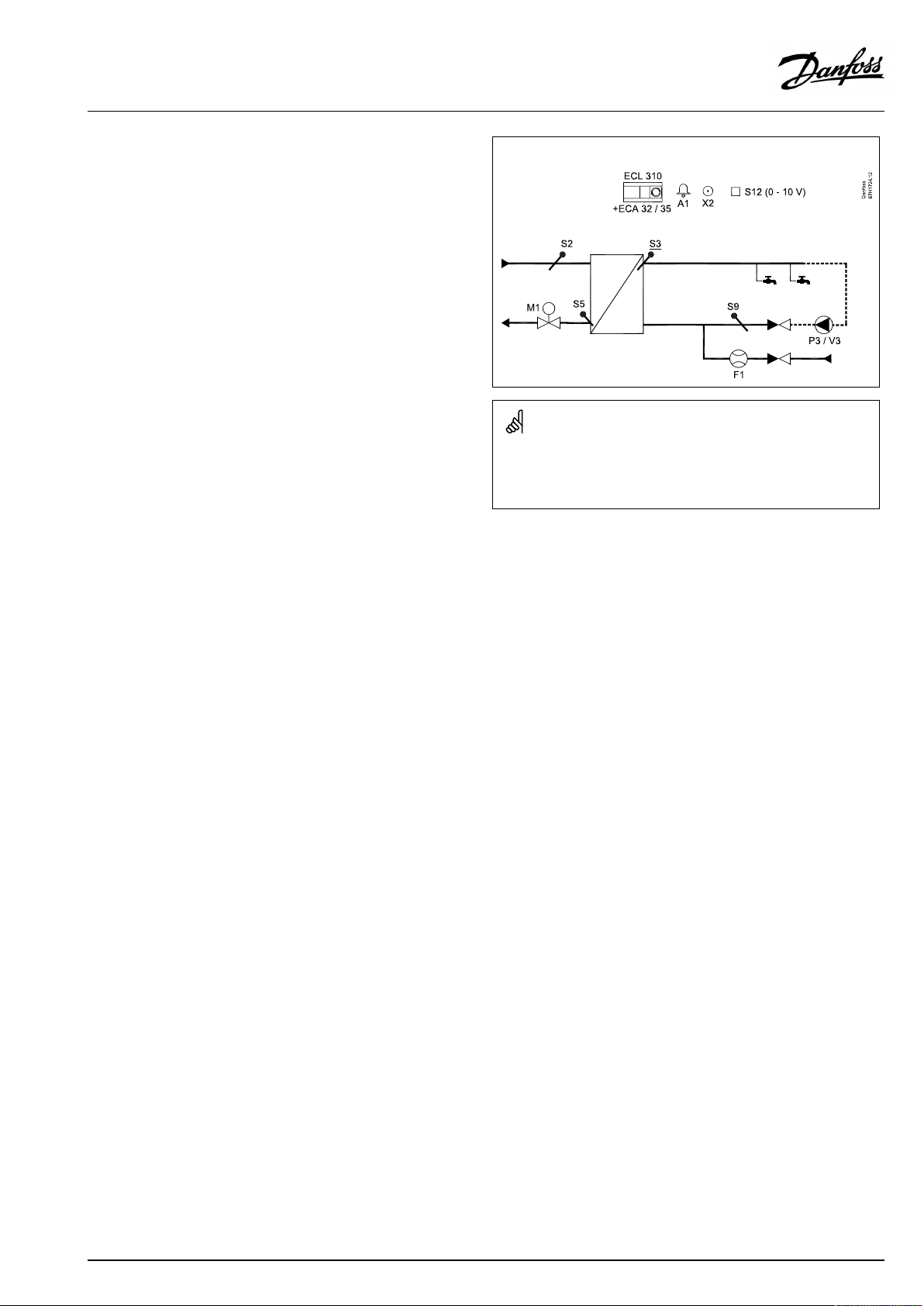
P318.10,ex.a,DHWapplicationwithcontrolvalve:
Theshowndiagramisafundamentalandsimplifiedexampleanddoes
notcontainallcomponentsthatarenecessaryinasystem.
AllnamedcomponentsareconnectedtotheECLComfortcontroller.
Listofcomponents:
ECL310
ECA32
ECA35
ECLComfort310controller
Built-inextensionmodule,0-10Voutputs
Built-inextensionmodule,0-10Voutputsand
PWMoutputs
S2
S3
Supplytemperaturesensor
(mandatory)DHWflowtemperaturesensor
S5Returntemperaturesensor
S9
S12
F1
P3
V3
DHWcirculationreturntemperaturesensor
0-10VinputfordesiredtemperatureatS3
ColdWatermeter(pulsesignal)
DHWcirculationpump(ON-OFFcontrolled)
Speedcontrolofcirculationpump(0-10Vor
PWM)
M1
X2
A1
Motorizedcontrolvalve(3-pointcontrolled)
Anti-bacteriafunctionisactive
Alarm
TheON-OFFoutputX2isONwhenanti-bacteriafunctionisactive.
VI.JM.Q5.02
©Danfoss|2018.09|19
Page 20

OperatingGuideECLComfort310,applicationP318
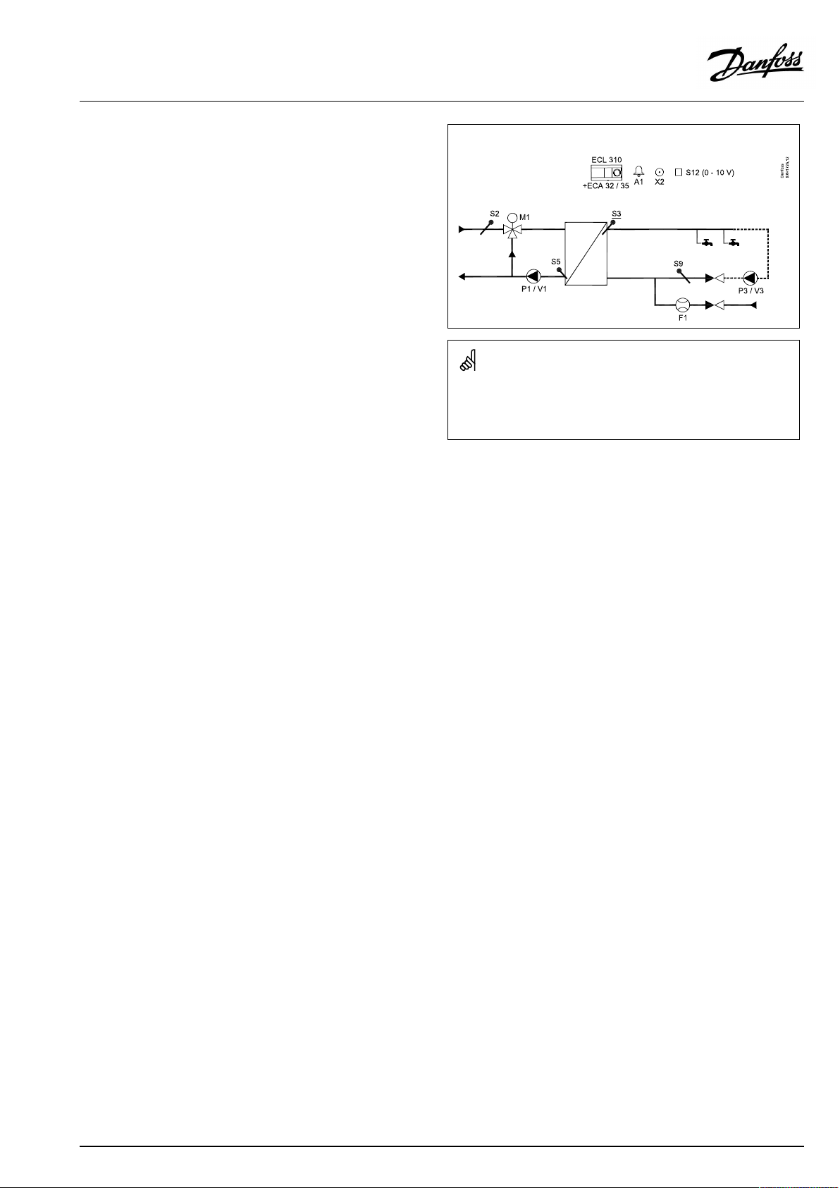
P318.10,ex.b,DHWapplicationwithcontrolpump:
Theshowndiagramisafundamentalandsimplifiedexampleanddoes
notcontainallcomponentsthatarenecessaryinasystem.
AllnamedcomponentsareconnectedtotheECLComfortcontroller.
Listofcomponents:
ECL310
ECA32
ECA35
ECLComfort310controller
Built-inextensionmodule,0-10Voutputs
Built-inextensionmodule,0-10Voutputsand
PWMoutputs
S2
S3
Supplytemperaturesensor
(mandatory)DHWflowtemperaturesensor
S5Returntemperaturesensor
S9
S12
F1
P1
V1
P3
V3
DHWcirculationreturntemperaturesensor
0-10VinputfordesiredtemperatureatS3
ColdWatermeter(pulsesignal)
Controlpump(ON-OFFcontrolled)
Speedcontrolofcontrolpump(0-10VorPWM)
DHWcirculationpump(ON-OFFcontrolled)
Speedcontrolofcirculationpump(0-10Vor
PWM)
X2
A1
Anti-bacteriafunctionisactive
Alarm
20|©Danfoss|2018.09
VI.JM.Q5.02
Page 21
OperatingGuideECLComfort310,applicationP318
P318.10,ex.c,DHWapplicationwithcontrolvalveandcontrolpump:
Theshowndiagramisafundamentalandsimplifiedexampleanddoes
notcontainallcomponentsthatarenecessaryinasystem.
AllnamedcomponentsareconnectedtotheECLComfortcontroller.
Listofcomponents:
ECL310
ECA32
ECA35
ECLComfort310controller
Built-inextensionmodule,0-10Voutputs
Built-inextensionmodule,0-10Voutputsand
PWMoutputs
S2
S3
Supplytemperaturesensor
(mandatory)DHWflowtemperaturesensor
S5Returntemperaturesensor
S9
S12
F1
P1
V1
P3
V3
DHWcirculationreturntemperaturesensor
0-10VinputfordesiredtemperatureatS3
ColdWatermeter(pulsesignal)
Controlpump(ON-OFFcontrolled)
Speedcontrolofcontrolpump(0-10VorPWM)
DHWcirculationpump(ON-OFFcontrolled)
Speedcontrolofcirculationpump(0-10Vor
PWM)
M1
X2
A1
Motorizedcontrolvalve(3-pointcontrolled)
Anti-bacteriafunctionisactive
Alarm
VI.JM.Q5.02
©Danfoss|2018.09|21
Page 22

OperatingGuideECLComfort310,applicationP318
Recommendations/consideringsettings:
Speed,P1/V1
"Voutmax. "/"Voutmin. "
(11165/11167)*
P318.10,ex.a
P318.10,ex.b
P318.10,ex.c
*)
Circuit1>MENU>Settings>Controlparameters1>
**)
Circuit1>MENU>Settings>Controlparameters1>
Max./min.tosamevalue
"Adapttime"(11065)*:OFF
Actuatorrunningtime
M1"Mrun"
(11186)**
X
X
22|©Danfoss|2018.09
VI.JM.Q5.02
Page 23
OperatingGuideECLComfort310,applicationP318
ThebasicprinciplesforapplicationP318.11:
AdvancedDHWtemperatureandbuffercontrol
ThedesiredDHWtemperatureatS3(setincircuit1,favoritedisplay
1)determinesthetemperaturecontrol.
TheDHWflowtemperaturesensorS3,thebuffertemperature
sensorsS6andS8arethemostimportantsensorsandmustbe
connected.IfS3isnotconnected,thecontrolpumpP1/V1will
stop;alternatively,thecontrolvalveM1(examplescandd)will
close.
TemperaturecontroloftheDHWcirculationpipeatS9ensuresthe
desiredtemperaturebymeansofspeedcontrolofpumpP3/V3.
AweekscheduleforswitchingtheDHWcirculationpumpONand
OFFcanbeset.
IfDHWcirculationreturntemperaturesensorS9isnotconnected,
theON-OFFcontrolledpumpwillbeONregardlesstheschedule
status.
Aspeed-controlledpumpcanbelimitedtoadesiredspeedby
meansofV.outmax.andV.outminsettings.
ThecontrolpumpP1/V1isincreasedinspeedwhentheDHW
flowtemperatureislowerthanthedesiredDHWflowtemperature
andviceversa.
Alternatively,themotorizedcontrolvalveM1(examplescandd)is
openedgraduallywhentheDHWflowtemperatureislowerthan
thedesiredDHWtemperatureandviceversa.
ThebufferisON/OFFcontrolledbymeansofP2orM2,operating
asON/OFFvalve,basedon3-pointcontrol.
Startbufferchargingprocess:
1.BuffertemperatureS6temperaturegetslowerthan('Desired
DHWtemperature'+'Startdifference').
Anexample:60°C+5)=65°C
2.X1isswitchedON
3.P2isswitchedON
Stopbufferchargingprocess:
1.BuffertemperatureS6temperaturegetshigherthan(2K+
'DesiredDHWtemperature'+'Startdifference)
AND
LowerbuffertemperatureS8getshigherthan('DesiredDHW
temperature'+'Stopdifference).
Anexample:
S6temperaturehigherthan(2+60°C+5)=67°C)
AND
S8temperaturehigherthan(60°C+(-3)=57°C).
2.P2isswitchedOFF
3.X1isswitchedOFF.
P318.11,ex.a,aapplicationwithDHWtemperaturecontrolandON/OFF
controlofbuffercharging.Inaddition,controlofreturnlayering:
Theshowndiagramisafundamentalandsimplifiedexampleanddoes
notcontainallcomponentsthatarenecessaryinasystem.
AllnamedcomponentsareconnectedtotheECLComfortcontroller.
Listofcomponents:
ECL310
ECA32
ECA35
ECLComfort310controller
Built-inextensionmodule,0-10Voutputs
Built-inextensionmodule,0-10Voutputsand
PWMoutputs
S2
S3
Supplytemperaturesensor
(mandatory)DHWtemperaturesensor
S5Returntemperaturesensor
S6
S8
S9
S12
F1
P1
(mandatory)Buffertemperaturesensor
(mandatory)Lowerbuffertemperaturesensor
DHWcirculationreturntemperaturesensor
0-10VinputfordesiredtemperatureatS3
ColdWatermeter(pulsesignal)
DHWtemperaturecontrolpump(ON-OFF
controlled)
V1
SpeedcontrolofDHWtemperaturecontrolpump
(0-10VorPWM)
P2
P3
V3
X1
X2
X3
A1
Bufferchargingpump(ON-OFFcontrolled)
Circulationpump(ON-OFFcontrolled)
Speedcontrolofcirculationpump(0-10VorPWM)
Bufferheatingdemandsignal
Anti-bacteriafunctionisactive
Change-overvalve,layeringcontrol
Alarm
VI.JM.Q5.02
©Danfoss|2018.09|23
Page 24
OperatingGuideECLComfort310,applicationP318
ReturnwaterfromDHWheat-exchangertobuffercanbedirected
bythechange-overvalveX3,basedontemperaturerelationship
betweenS5andS8.
Thisreturnlayeringfunctiondirectslowtemperaturewaterto
buffer-bottomorhighertemperaturewatertobuffer-mid.
Differentialtemperaturesforlayeringcontrolcanbeset.
ThesupplytemperatureS2isusedtocompensatetheproportional
bandXpforimprovingthetemperaturecontrolatdifferentsupply
temperatures.
ThewaterflowsignalfromF1canbeusedtooverridethe
controlvalveforoptimizingtheDHWtemperaturecontrol.This
pro-activefunctionalitycompensatesforthedelaybeforetheflow
temperaturesensorS3measuresachangeintemperature.
ThewaterflowsignalcanalsobeutilizedforcontroloftheS3
temperature,evenifthereisnoDHWcirculation.
Asanoption,thedesiredDHWtemperaturecanbesetexternally.
Avoltagesignal(1-10Volt)canbeappliedtoinputS12(ECA32/
35).Thescaleforvoltageversustemperaturecanbeset.
TheON-OFFoutputX1isONatbufferheatingdemand.
Ananti-bacteriafunctionfortheDHWcircuitisavailablefor
activationonselecteddaysoftheweek.
Theanti-bacteriafunctioncanbesettoincludetheDHW
circulation.
TheON-OFFoutputX2isONwhenanti-bacteriafunctionisactive.
Bymeansofaweekschedule,theDHWcirculationcanbeON/OFF
controlled;thisispossiblewhenS9isconnected.
P318.11,ex.b,applicationwithDHWtemperaturecontrolandON/OFF
controlofbuffercharging.Inaddition,controlofreturnlayering.
Theshowndiagramisafundamentalandsimplifiedexampleanddoes
notcontainallcomponentsthatarenecessaryinasystem.
AllnamedcomponentsareconnectedtotheECLComfortcontroller.
Listofcomponents:
ECL310
ECA32
ECA35
ECLComfort310controller
Built-inextensionmodule,0-10Voutputs
Built-inextensionmodule,0-10Voutputsand
PWMoutputs
S2
S3
Supplytemperaturesensor
(mandatory)DHWtemperaturesensor
S5Returntemperaturesensor
S6
S8
S9
S12
F1
P1
(mandatory)Buffertemperaturesensor
(mandatory)Lowerbuffertemperaturesensor
DHWcirculationreturntemperaturesensor
0-10VinputfordesiredtemperatureatS3
ColdWatermeter(pulsesignal)
DHWtemperaturecontrolpump(ON-OFF
controlled)
V1
SpeedcontrolofDHWtemperaturecontrolpump
(0-10VorPWM)
P2/M2
P3
V3
Bufferchargingvalve(ON-OFFcontrolled)
Circulationpump(ON-OFFcontrolled)
Speedcontrolofcirculationpump(0-10Vor
PWM)
X1
X2
X3
A1
Bufferheatingdemandsignal
Anti-bacteriafunctionisactive
Change-overvalve,layeringcontrol
Alarm
24|©Danfoss|2018.09
VI.JM.Q5.02
Page 25
OperatingGuideECLComfort310,applicationP318
P318.11,ex.c,applicationwithDHWtemperaturecontrolandON/OFF
controlofbuffercharging.Inaddition,controlofreturnlayering.
Theshowndiagramisafundamentalandsimplifiedexampleanddoes
notcontainallcomponentsthatarenecessaryinasystem.
AllnamedcomponentsareconnectedtotheECLComfortcontroller.
Listofcomponents:
ECL310
ECA32
ECA35
ECLComfort310controller
Built-inextensionmodule,0-10Voutputs
Built-inextensionmodule,0-10Voutputsand
PWMoutputs
S2
S3
Supplytemperaturesensor
(mandatory)DHWtemperaturesensor
S5Returntemperaturesensor
S6
S8
S9
S12
F1
P1
(mandatory)Buffertemperaturesensor
(mandatory)Lowerbuffertemperaturesensor
DHWcirculationreturntemperaturesensor
0-10VinputfordesiredtemperatureatS3
ColdWatermeter(pulsesignal)
DHWtemperaturecontrolpump(ON-OFF
controlled)
V1
SpeedcontrolofDHWtemperaturecontrolpump
(0-10VorPWM)
P2
P3
V3
Bufferchargingpump(ON-OFFcontrolled)
Circulationpump(ON-OFFcontrolled)
Speedcontrolofcirculationpump(0-10Vor
PWM)
M1
X1
X2
X3
A1
Motorizedcontrolvalve(3-pointcontrolled)
Bufferheatingdemandsignal
Anti-bacteriafunctionisactive
Change-overvalve,layeringcontrol
Alarm
VI.JM.Q5.02
©Danfoss|2018.09|25
Page 26
OperatingGuideECLComfort310,applicationP318
P318.11,ex.d,applicationwithDHWtemperaturecontrolandON/OFF
controlofbuffercharging.Inaddition,controlofreturnlayering.
Theshowndiagramisafundamentalandsimplifiedexampleanddoes
notcontainallcomponentsthatarenecessaryinasystem.
AllnamedcomponentsareconnectedtotheECLComfortcontroller.
Listofcomponents:
ECL310
ECA32
ECA35
ECLComfort310controller
Built-inextensionmodule,0-10Voutputs
Built-inextensionmodule,0-10Voutputsand
PWMoutputs
S2
S3
Supplytemperaturesensor
(mandatory)DHWtemperaturesensor
S5Returntemperaturesensor
S6
S8
S9
S12
F1
P1
(mandatory)Buffertemperaturesensor
(mandatory)Lowerbuffertemperaturesensor
DHWcirculationreturntemperaturesensor
0-10VinputfordesiredtemperatureatS3
ColdWatermeter(pulsesignal)
DHWtemperaturecontrolpump(ON-OFF
controlled)
V1
SpeedcontrolofDHWtemperaturecontrolpump
(0-10VorPWM)
P2/M2
P3
V3
Bufferchargingvalve(ON-OFFcontrolled)
Circulationpump(ON-OFFcontrolled)
Speedcontrolofcirculationpump(0-10Vor
PWM)
M1
X1
X2
X3
A1
Motorizedcontrolvalve(3-pointcontrolled)
Bufferheatingdemandsignal
Anti-bacteriafunctionisactive
Change-overvalve,layeringcontrol
Alarm
26|©Danfoss|2018.09
VI.JM.Q5.02
Page 27

OperatingGuideECLComfort310,applicationP318
Recommendations/consideringsettings:
Speed,P1/V1
"Voutmax. "/"Voutmin. "
(11165/11167)*
P318.11,ex.a
P318.11,ex.b
P318.11,ex.c
P318.11,ex.dMax./min.tosamevalue
*)
Circuit1>MENU>Settings>Controlparameters1>
**)
Circuit1>MENU>Settings>Controlparameters1>
P318,ingeneral
UptotwoRemoteControlUnits,ECA30/31,canbeconnectedto
oneECLcontrollerinordertocontroltheECLcontrollerremotely.
AdditionalECLComfortcontrollerscanbeconnectedviatheECL
485businordertoutilizecommonoutdoortemperaturesignal,
timeanddatesignals.TheECLControllersintheECL485bus
systemcanworkasmasterandslaves.TheapplicationP318can
workaloneorasaslave.
Max./min.tosamevalue
"Adapttime"(11065)*:OFF
"Adapttime"(11065)*:OFF
Actuatorrunningtime
M1"Mrun"
(11186)**
X
X
Heat-meters:
Upto5heat-meterscanbeconnectedtotheM-busterminals.
DatacanbetransferredtotheSCADAsystemviaModbusandTCP/
IPtotheECLPortal.
TheP318applicationhaseventindicationsfor
•Chargingtemperature
•Tank(buffer)temperature
•DHWflowtemperature
•Supplytemperature
•Anti-bacteria
Typically,aneventisregisteredifasettemperatureconditionis
notaccepted.Theeventscanbeprioritizedtobeindicatedas
informationoranalarm.
ThealarmA1(=relay6)canbeactivatedif:
•aneventoccurs
•atemperaturesensororitsconnectiondisconnects/short
circuits.(See:Commoncontrollersettings>System>Raw
inputoverview).
VI.JM.Q5.02
©Danfoss|2018.09|27
Page 28

OperatingGuideECLComfort310,applicationP318
PWM(PulseWidthModulation)
A200HzfrequencyisappliedtothePWMcontrolledpump.The
dutycycle(thepercentageoftheperiodtime)determinesthe
pumpspeed.
Pumpspeed,PWMor0–10Voltcontrolled
Sometypesofspeedcontrolledpumpsarelimitedtoaminimum
speed,forexample30%(PWMor3.0Volt).Eveniftheapplied
control%getslowerthan30%,thepumpspeedremainsonthe
minimumlevel*.
Furthermore,whentheappliedcontrol%getsbelow,forexample,
10%,thepumpswitchesOFF.Inordertogetthepumpswitched
ONagain,theappliedcontrol%mustexceed20%.
Thisbehaviorcan,atlowloadoratoobigpump,causeunstable
temperatureregulation.Toavoidthis,theP318hasafunction
wheretheappliedcontrolsignalisconvertedintoapulsedsignal.
Thepumpisshortlystoppedandthenstartedagain.Theresultisa
pumpspeedcontrolalsobelowtheminimumspeedlevel.
Theparameters"PWMperiod"(ID11565)and"Adapttime"(ID
11065)areusedforthisfunctionality.
*)Seethepumpmanufacturer'sdatasheet
Inputconfiguration
Inputs(asfromS7andup)whicharenotpartoftheapplicationcan
beconfiguredtobePt1000,0-10Volt,frequency(pulsecounter)
orDigitalinput.Thisfeaturemakesitpossibletocommunicate
extrasignals,suchastemperatures,pressures,ON/OFFconditions,
viaModbusandECLPortal.
TheconfigurationisdonebymeansoftheECLTool(freesoftware
fordownload)ordirectlyinadedicatedmenuintheECLPortalor
theconnectionforModbus(BMS/SCADA).
Commissioning
WhentheP318applicationhasbeenuploaded,theECLComfort
310controllerstartsinManualmode.Thiscanbeusedtoverify
correctconnectionsofinputrelatedcomponents,forexample
temperatureandpressuresensorsandflowmeters.
Inaddition,controlledcomponentscanbeverifiedforcorrect
functionality.
Theapplicationkeyisdeliveredwithfactorysettings.Depending
onsystemtype,itisrecommendedtochangesomeofthesettings
individuallyforoptimizingthefunctionality.
Thesesettingchanges,ifrequired,arelistedaftertheexplanation
ofeachsubtype(Seesection"Beforeyoustart")
Important:
Setthecorrectrunningtime"Mrun"ofMotorizedControlValve(s)
(CircuitX>MENU>Settings>Controlparameters>Mrun).
Theapplicationkeymustbeinsertedinordertochangesettings.
Thecontrollerispre-programmedwithfactorysettingsthatareshown
inthe‘ParameterIDoverview’appendix.
28|©Danfoss|2018.09
VI.JM.Q5.02
Page 29

OperatingGuideECLComfort310,applicationP318
2.2Identifyingthesystemtype
Sketchyourapplication
TheECLComfortcontrollerseriesisdesignedforawiderange
ofheating,domestichot-water(DHW)andcoolingsystemswith
differentconfigurationsandcapacities.Ifyoursystemdiffers
fromthediagramsshownhere,youmaywanttomakeasketch
ofthesystemabouttobeinstalled.Thismakesiteasiertouse
theOperatingGuide,whichwillguideyoustep-by-stepfrom
installationtofinaladjustmentsbeforetheend-usertakesover.
TheECLComfortcontrollerisauniversalcontrollerthatcanbe
usedforvarioussystems.Basedontheshownstandardsystems,
itispossibletoconfigureadditionalsystems.Inthischapteryou
findthemostfrequentlyusedsystems.Ifyoursystemisnotquite
asshownbelow,findthediagramwhichhasthebestresemblance
withyoursystemandmakeyourowncombinations.
SeetheInstallationGuide(deliveredwiththeapplicationkey)for
applicationtypes/sub-types.
Adviceforsettings:
Factorysettingsinthesubtypesarerelatedtotheexamplesa.
Someoftheapplicationexamplesneedchangeofdedicated
settings.
Seethelistaftertheexplanationofeachsubtype(Seesection
"Beforeyoustart")
VI.JM.Q5.02
©Danfoss|2018.09|29
Page 30
OperatingGuideECLComfort310,applicationP318
2.3Mounting
2.3.1MountingtheECLComfortcontroller
SeetheInstallationGuidewhichisdeliveredtogetherwiththe
ECLComfortcontroller.
Foreasyaccess,youshouldmounttheECLComfortcontrollernear
thesystem.
ECLComfort210/296/310canbemounted
•onawall
•onaDINrail(35mm)
ECLComfort296canbemounted
•inapanelcut-out
ECLComfort210canbemountedinanECLComfort310basepart
(forfutureupgrade).
Screws,PGcableglandsandrawlplugsarenotsupplied.
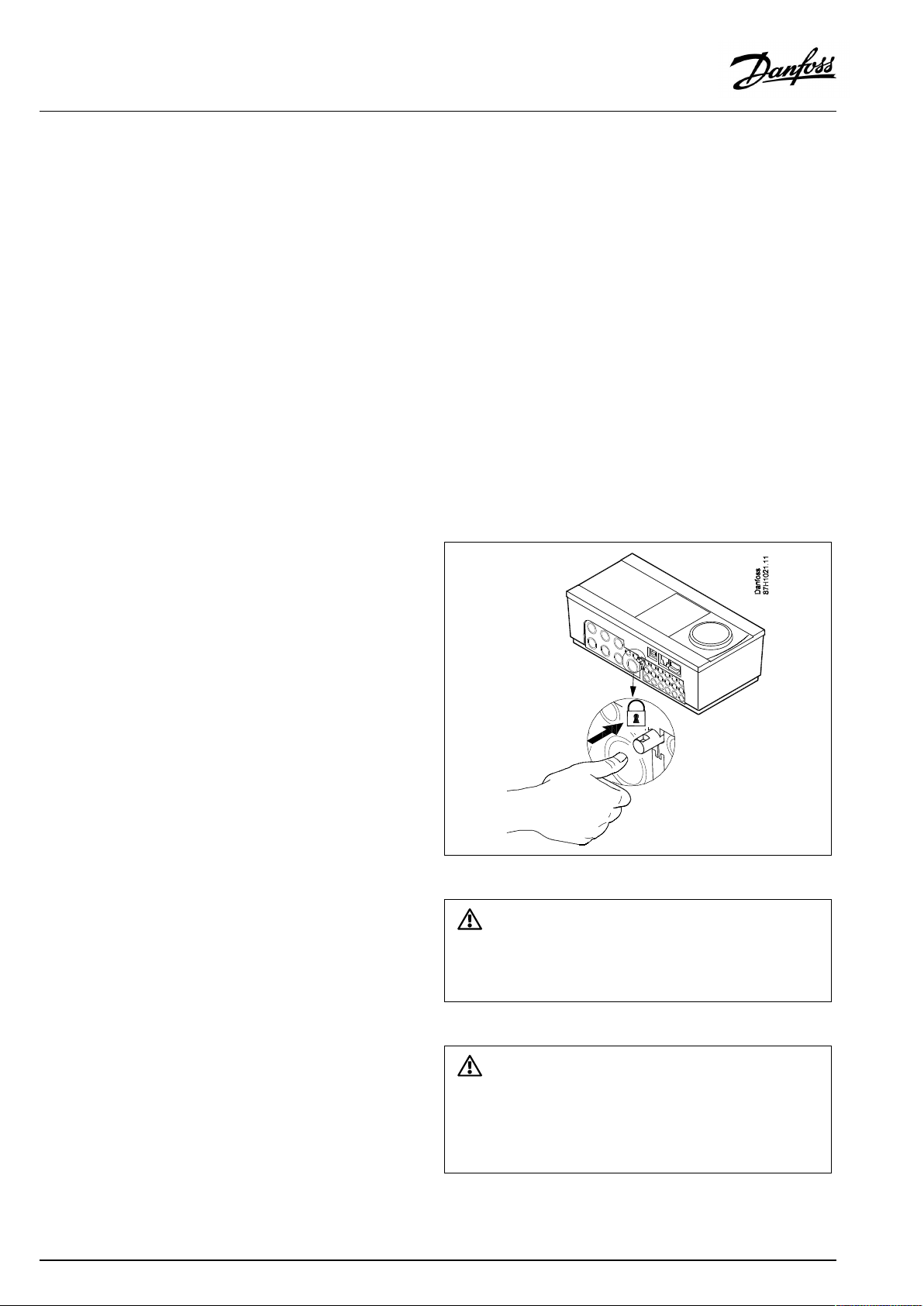
LockingtheECLComfort210/310controller
InordertofastentheECLComfortcontrollertoitsbasepart,secure
thecontrollerwiththelockingpin.
30|©Danfoss|2018.09
Topreventinjuriestopersonsorthecontroller,thecontrollerhasto
besecurelylockedintothebase.Forthispurpose,pressthelocking
pinintothebaseuntilaclickisheardandthecontrollernolonger
canberemovedfromthebase.
Ifthecontrollerisnotsecurelylockedintothebasepart,thereisarisk
thatthecontrollerduringoperationcanunlockfromthebaseandthe
basewithterminals(andalsothe230Va.c.connections)areexposed.
Topreventinjuriestopersons,alwaysmakesurethatthecontroller
issecurelylockedintoitsbase.Ifthisisnotthecase,thecontroller
shouldnotbeoperated!
VI.JM.Q5.02
Page 31

OperatingGuideECLComfort310,applicationP318
Mountingonawall
Mountthebasepartonawallwithasmoothsurface.Establishthe
electricalconnectionsandpositionthecontrollerinthebasepart.
Securethecontrollerwiththelockingpin.
MountingonaDINrail(35mm)
MountthebasepartonaDINrail.Establishtheelectrical
connectionsandpositionthecontrollerinthebasepart.Secure
thecontrollerwiththelockingpin.
Theeasywaytolockthecontrollertoitsbaseorunlockitistousea
screwdriveraslever.
DismountingtheECLComfortcontroller
Inordertoremovethecontrollerfromthebasepart,pulloutthe
lockingpinbymeansofascrewdriver.Thecontrollercannowbe
removedfromthebasepart.
Theeasywaytolockthecontrollertoitsbaseorunlockitistousea
screwdriveraslever.
VI.JM.Q5.02
©Danfoss|2018.09|31
Page 32

OperatingGuideECLComfort310,applicationP318
2.3.2MountingtheRemoteControlUnitsECA30/31
Selectoneofthefollowingmethods:
•Mountingonawall,ECA30/31
•Mountinginapanel,ECA30
Screwsandrawlplugsarenotsupplied.
Mountingonawall
MountthebasepartoftheECA30/31onawallwithasmooth
surface.Establishtheelectricalconnections.PlacetheECA30/
31inthebasepart.
BeforeremovingtheECLComfortcontrollerfromthebasepart,ensure
thatthesupplyvoltageisdisconnected.
Mountinginapanel
MounttheECA30inapanelusingtheECA30framekit(ordercode
no.087H3236).Establishtheelectricalconnections.Securethe
framewiththeclamp.PlacetheECA30inthebasepart.TheECA
30canbeconnectedtoanexternalroomtemperaturesensor.
TheECA31mustnotbemountedinapanelifthehumidity
functionistobeused.
32|©Danfoss|2018.09
VI.JM.Q5.02
Page 33

OperatingGuideECLComfort310,applicationP318
2.3.3MountingtheinternalI/OmoduleECA32orECA35
TheECA32module(ordercodeno.087H3202)orECA35module
(ordercodeno.087H3205)canbeinsertedintotheECLComfort
310/310Bbasepartforadditionalinputandoutputsignalsin
relevantapplications.
ECA32
ECA35
VI.JM.Q5.02
©Danfoss|2018.09|33
Page 34

OperatingGuideECLComfort310,applicationP318
2.4Placingthetemperaturesensors
2.4.1Placingthetemperaturesensors
Itisimportantthatthesensorsaremountedinthecorrectposition
inyoursystem.
Thetemperaturesensormentionedbelowaresensorsusedforthe
ECLComfort210/296/310serieswhichnotallwillbeneeded
foryourapplication!
Outdoortemperaturesensor(ESMT)
Theoutdoorsensorshouldbemountedonthatsideofthebuilding
whereitislesslikelytobeexposedtodirectsunshine.Itshouldnot
beplacedclosetodoors,windowsorairoutlets.
Flowtemperaturesensor(ESMU,ESM-11orESMC)
Placethesensormax.15cmfromthemixingpoint.Insystems
withheatexchanger,DanfossrecommendsthattheESMU-typeto
beinsertedintotheexchangerflowoutlet.
Makesurethatthesurfaceofthepipeiscleanandevenwhere
thesensorismounted.
Returntemperaturesensor(ESMU,ESM-11orESMC)
Thereturntemperaturesensorshouldalwaysbeplacedsothatit
measuresarepresentativereturntemperature.
Roomtemperaturesensor
(ESM-10,ECA30/31RemoteControlUnit)
Placetheroomsensorintheroomwherethetemperatureistobe
controlled.Donotplaceitonoutsidewallsorclosetoradiators,
windowsordoors.
Boilertemperaturesensor(ESMU,ESM-11orESMC)
Placethesensoraccordingtotheboilermanufacturer’s
specification.
Airducttemperaturesensor(ESMB-12orESMUtypes)
Placethesensorsothatitmeasuresarepresentativetemperature.
DHWtemperaturesensor(ESMUorESMB-12)
PlacetheDHWtemperaturesensoraccordingtothemanufacturer’s
specification.
Slabtemperaturesensor(ESMB-12)
Placethesensorinaprotectiontubeintheslab.
ESM-11:Donotmovethesensorafterithasbeenfastenedinorderto
avoiddamagetothesensorelement.
ESM-11,ESMCandESMB-12:Useheatconductingpasteforquick
measurementofthetemperature.
ESMUandESMB-12:Usingasensorpockettoprotectthesensorwill,
however,resultinaslowertemperaturemeasurement.
34|©Danfoss|2018.09
VI.JM.Q5.02
Page 35

OperatingGuideECLComfort310,applicationP318
Pt1000temperaturesensor(IEC751B,1000Ω/0°C)
Relationshipbetweentemperatureandohmicvalue:
VI.JM.Q5.02
©Danfoss|2018.09|35
Page 36

OperatingGuideECLComfort310,applicationP318
2.5Electricalconnections
2.5.1Electricalconnections230Va.c.
SafetyNote
Necessaryassembly,start-up,andmaintenanceworkmustbe
performedbyqualifiedandauthorizedpersonnelonly.
Locallegislationsmustberespected.Thiscomprisesalsocablesize
andisolation(reinforcedtype).
AfusefortheECLComfortinstallationismax.10Atypically.
TheambienttemperaturerangefortheECLComfortinoperationis
0-55°C.Exceedingthistemperaturerangecanresultinmalfunctions.
Installationmustbeavoidedifthereisariskforcondensation(dew).
Thecommongroundterminalisusedforconnectionofrelevant
components(pumps,motorizedcontrolvalves).
SeealsotheInstallationGuide(deliveredwiththeapplicationkey)
forapplicationspecificconnections.
ECL210/310
Wirecrosssection:0.5-1.5mm²
Incorrectconnectioncandamagetheelectronicoutputs.
Max.2x1.5mm²wirescanbeinsertedintoeachscrewterminal.
Maximumloadratings:
36|©Danfoss|2018.09
Relayterminals
Triac(=electronic
relay)terminals
4(2)A/230Va.c.
(4Aforohmicload,2Afor
inductiveload)
0,2A/230Va.c.
VI.JM.Q5.02
Page 37

OperatingGuideECLComfort310,applicationP318
Electricalconnections,ECA32/ECA35
Connections,ingeneral.
SeealsotheInstallationGuide(deliveredwiththeapplicationkey)forapplicationspecificconnections.
Maximumloadratings:
Terminals
ECA32ECA35
PWMOut1(52)
PWMOut2(53)
PWMOut3(54)
PWMOut4(55)
AnalogOut1(59)AnalogOut1(59)47kΩ*
AnalogOut2(60)AnalogOut2(60)47kΩ*
AnalogOut3(61)AnalogOut3(61)47kΩ*
*Thevalueisaminimum.
5kΩ*
5kΩ*
5kΩ*
5kΩ*
VI.JM.Q5.02
©Danfoss|2018.09|37
Page 38

OperatingGuideECLComfort310,applicationP318
2.5.2Electricalconnections,Pt1000temperaturesensorsandsignals
SeetheInstallationGuide(deliveredwiththeapplicationkey)for
sensorandinputconnections.
Applicationdiagramsshowmandatorytemperaturesensorswith
anunderscore;exampleS3.
P318
Sensor
S1
S2
S3*
S4*
S5Returntemperature
S6P318.1,P318.2,
S7
S8P318.1,P318.2,
S9
S10
Description
Notused
Supplytemperature
sensor
P318.1,P318.2:
Chargingtemperature
sensor
P318.10,P318.11:
DHWflowtemperature
sensor
P318.2:
DHWflowtemperature
sensor
sensor
P318.11:Upper
buffer-tank
temperaturesensor
P318.10:Notused
Notused
P318.11:Lower
buffer-tank
temperaturesensor
P318.10:Notused
DHWcirculation
temperaturesensor
Notused
Recommended
type
ESM-11/
ESMB/
ESMC/
ESMU
ESM-11/
ESMB/
ESMC/
ESMU
ESM-11/
ESMB/
ESMC/
ESMU
ESMB/
ESMU
ESMB/
ESMU
ESM-11/
ESMB/
ESMC/
ESMU
Temperaturesensorsmustbeconnectedinordertohavethe
desiredfunctionality.
*
Ifthesensorisnotconnectedorthesensorcableis
short-circuited,themotorizedcontrolvalveorcontrolpump
closes/stops(safetyfunction).
38|©Danfoss|2018.09
VI.JM.Q5.02
Page 39

OperatingGuideECLComfort310,applicationP318
Wirecrosssectionforsensorconnections:Min.0.4mm².
Totalcablelength:Max.200m(allsensorsincl.internalECL485
communicationbus).
Cablelengthsofmorethan200mmaycausenoisesensibility(EMC).
VI.JM.Q5.02
©Danfoss|2018.09|39
Page 40

OperatingGuideECLComfort310,applicationP318
2.5.3Electricalconnections,ECA30/31
Terminal
ECL
Terminal
ECA30/31
30
31
4
1
322
333
4
5
*
Afteranexternalroomtemperaturesensorhasbeenconnected,
Description
Twistedpair
Twistedpair
Ext.roomtemperature
sensor*
Type
(recomm.)
Cable2x
twistedpair
ESM-10
ECA30/31mustberepowered.
ThecommunicationtotheECA30/31mustbesetupintheECL
Comfortcontrollerin'ECAaddr.'
TheECA30/31mustbesetupaccordingly.
AfterapplicationsetuptheECA30/31isreadyafter2–5min.A
progressbarintheECA30/31isdisplayed.
Iftheactualapplicationcontainstwoheatingcircuits,itispossible
toconnectanECA30/31toeachcircuit.Theelectricalconnections
aredoneinparallel.
Max.2ECA30/31canbeconnectedtoanECLComfort310controller
ortoECLComfort210/296/310controllersinamaster-slavesystem.
SetupproceduresforECA30/31:Seesection‘Miscellaneous’ .
ECAinformationmessage:
‘Applicationreq.newerECA’:
Thesoftware(firmware)ofyourECAdoesnotcomplywiththe
software(firmware)ofyourECLComfortcontroller.Pleasecontact
yourDanfosssalesoffice.
Someapplicationsdonotcontainfunctionsrelatedtoactualroom
temperature.TheconnectedECA30/31willonlyfunctionasremote
control.
40|©Danfoss|2018.09
VI.JM.Q5.02
Page 41

OperatingGuideECLComfort310,applicationP318
ECA32/35
S12
Connectionofvoltagesignal(0–10V)forexternalcontrolofdesired
DHWtemperature.
Theappliedvoltagemust,asaminimum,be1Volt.
Totalcablelength:Max.200m(allsensorsincl.internalECL485
communicationbus).
Cablelengthsofmorethan200mmaycausenoisesensibility(EMC).
VI.JM.Q5.02
©Danfoss|2018.09|41
Page 42

OperatingGuideECLComfort310,applicationP318
2.5.4Electricalconnections,master/slavesystems
Thecontrollercanbeusedasmasterorslaveinmaster/slave
systemsviatheinternalECL485communicationbus(2xtwisted
paircable).
TheECL485communicationbusisnotcompatiblewiththeECL
businECLComfort110,200,300and301!
Terminal
31*
Description
30
Commonterminal
+12V*,ECL485communicationbus
32
B,ECL485communicationbus
33
A,ECL485communicationbus
*OnlyforECA30/31andmaster/slavecommunication
Type
(recomm.)
Cable2x
twistedpair
Totalcablelength:Max.200m(allsensorsincl.internalECL485
communicationbus).
Cablelengthsofmorethan200mmaycausenoisesensibility(EMC).
ECL485buscable
MaximumrecommendedlengthoftheECL485busiscalculatedlike
this:
Subtract"TotallengthofallinputcablesofallECLcontrollersinthe
master-slavesystem"from200m.
Simpleexamplefortotallengthofallinputcables,3xECL:
1xECL
3xECL
3xECLReturntemp.sensor:
3xECLRoomtemp.sensor:
Total:
MaximumrecommendedlengthoftheECL485bus:
200-81m=119m
Outdoortemp.sensor:
Flowtemp.sensor:
15m
18m
18m
30m
81m
42|©Danfoss|2018.09
VI.JM.Q5.02
Page 43

OperatingGuideECLComfort310,applicationP318
2.5.5Electricalconnections,communication
Electricalconnections,Modbus
ECLComfort210:Non-galvanicisolatedModbusconnections
ECLComfort296:GalvanicisolatedModbusconnections
ECLComfort310:GalvanicisolatedModbusconnections
Electricalconnections,M-bus
ECLComfort210:Notimplemented
ECLComfort296:Onboard
ECLComfort310:Onboard
Example,M-busconnections
(ECLComfort296/310and310Bonly)
VI.JM.Q5.02
©Danfoss|2018.09|43
Page 44

OperatingGuideECLComfort310,applicationP318
2.6InsertingtheECLApplicationKey
2.6.1InsertingtheECLApplicationKey
TheECLApplicationKeycontains
•theapplicationanditssubtypes,
•currentlyavailablelanguages,
•factorysettings:e.g.schedules,desiredtemperatures,
limitationvaluesetc.Itisalwayspossibletorecoverthefactory
settings,
•memoryforusersettings:specialuser/systemsettings.
Afterhavingpowered-upthecontroller,differentsituationsmight
beexisting:
1.Thecontrollerisnewfromthefactory,theECLApplicationKey
isnotinserted.
2.Thecontrolleralreadyrunsanapplication.TheECLApplication
Keyisinserted,buttheapplicationneedstobechanged.
3.Acopyofthecontrollerssettingsisneededforconfiguring
anothercontroller.
ECLComfort210/310
ECLComfort210/310
Usersettingsare,amongothers,desiredroomtemperature,desired
DHWtemperature,schedules,heatcurve,limitationvaluesetc.
Systemsettingsare,amongothers,communicationset-up,display
brightnessetc.
44|©Danfoss|2018.09
VI.JM.Q5.02
Page 45

OperatingGuideECLComfort310,applicationP318
Automaticupdateofcontrollersoftware(firmware):
Thesoftwareofthecontrollerisupdatedautomaticallywhenthekey
isinserted(asofcontrollerversion1.11(ECL210/310)andversion
1.58(ECL296)).Thefollowinganimationwillbeshownwhenthe
softwareisbeingupdated:
Progressbar
Duringupdate:
•DonotremovetheKEY
Ifthekeyisremovedbeforethehour-glassisshown,youhave
tostartafresh.
•Donotdisconnectthepower
Ifthepowerisinterruptedwhenthehour-glassisshown,the
controllerwillnotwork.
•Manualupdateofcontrollersoftware(firmware):
Seethesection"Automatic/manualupdateoffirmware"
The“Keyoverview”doesnotinform—throughECA30/31—about
thesubtypesoftheapplicationkey.
Keyinserted/notinserted,description:
ECLComfort210/310,controllerversionslowerthan1.36:
-
Takeouttheapplicationkey;for20minutes
settingscanbechanged.
-
Powerupthecontrollerwithoutthe
applicationkeyinserted;for20minutes
settingscanbechanged.
ECLComfort210/310,controllerversions1.36andup:
-
Takeouttheapplicationkey;for20minutes
settingscanbechanged.
-
Powerupthecontrollerwithoutthe
applicationkeyinserted;settingscannotbe
changed.
ECLComfort296,controllerversions1.58andup:
-
Takeouttheapplicationkey;for20minutes
settingscanbechanged.
-
Powerupthecontrollerwithoutthe
applicationkeyinserted;settingscannotbe
changed.
VI.JM.Q5.02
©Danfoss|2018.09|45
Page 46

OperatingGuideECLComfort310,applicationP318
ApplicationKey:Situation1
Thecontrollerisnewfromthefactory,theECLApplicationKey
isnotinserted.
AnanimationfortheECLApplicationKeyinsertionisdisplayed.
InserttheApplicationKey.
ApplicationKeynameandVersionisindicated(example:A266
Ver.1.03).
IftheECLApplicationKeyisnotsuitableforthecontroller,a"cross"
isdisplayedovertheECLApplicationKey-symbol.
Action:Purpose:
Selectlanguage
Confirm
Selectapplication(subtype)
Somekeyshaveonlyoneapplication.
Confirmwith‘Yes’
Set'Time&Date'
Turnandpushthedialtoselectand
change'Hours' ,'Minutes','Date',
'Month'and'Year' .
Choose''Next'
Confirmwith‘Yes’
Goto‘Aut.daylight’
Choosewhether‘ Aut.daylight´*
shouldbeactiveornot
*‘Aut.daylight’istheautomaticchangeoverbetweensummer
andwintertime.
DependingonthecontentsoftheECLApplicationKey,procedure
AorBistakingplace:
A
TheECLApplicationkeycontainsfactorysettings:
Thecontrollerreads/transfersdatafromtheECLApplicationKey
toECLcontroller.
Examples:
YESorNO
Theapplicationisinstalled,andthecontrollerresetsandstartsup.
B
TheECLApplicationkeycontainschangedsystemsettings:
Pushthedialrepeatedly.
’NO’:
’YES*:
Ifthekeycontainsusersettings:
Pushthedialrepeatedly.
‘NO:
‘YES*:
*If‘YES’cannotbechosen,theECLApplicationKeydoesnot
containanyspecialsettings.
Choose‘Startcopying’andconfirmwith'Yes'.
46|©Danfoss|2018.09
OnlyfactorysettingsfromtheECLApplicationKeywill
becopiedtothecontroller.
Specialsystemsettings(differingfromthefactory
settings)willbecopiedtothecontroller.
OnlyfactorysettingsfromtheECLApplicationKeywill
becopiedtothecontroller.
Specialusersettings(differingfromthefactorysettings)
willbecopiedtothecontroller.
VI.JM.Q5.02
Page 47

OperatingGuideECLComfort310,applicationP318
(Example):
The"i"intheupperrightcornerindicatesthat-besidesthefactory
settings-thesubtypealsocontainsspecialuser/systemssettings.
ApplicationKey:Situation2
Thecontrolleralreadyrunsanapplication.TheECLApplication
Keyisinserted,buttheapplicationneedstobechanged.
TochangetoanotherapplicationontheECLApplicationKey,the
currentapplicationinthecontrollermustbeerased(deleted).
BeawarethattheApplicationKeymustbeinserted.
Action:Purpose:
Choose‘MENU’inanycircuit
Confirm
Choosethecircuitselectoratthetop
rightcornerinthedisplay
Confirm
Choose‘Commoncontrollersettings’
Confirm
Choose‘Keyfunctions’
Confirm
Choose‘Eraseapplication’
Confirmwith‘Yes’
Thecontrollerresetsandisreadytobeconfigured.
Followtheproceduredescribedinsituation1.
Examples:
VI.JM.Q5.02
©Danfoss|2018.09|47
Page 48

OperatingGuideECLComfort310,applicationP318
ApplicationKey:Situation3
Acopyofthecontrollerssettingsisneededforconfiguring
anothercontroller.
Thisfunctionisused
•forsaving(backup)ofspecialuserandsystemsettings
•whenanotherECLComfortcontrollerofthesametype(210,
296or310)mustbeconfiguredwiththesameapplicationbut
user/systemsettingsdifferfromthefactorysettings.
HowtocopytoanotherECLComfortcontroller:
Action:Purpose:
Choose‘MENU’
Confirm
Choosethecircuitselectoratthetop
rightcornerinthedisplay
Confirm
Choose'Commoncontrollersettings'
Confirm
Goto‘Keyfunctions’
Confirm
Choose‘Copy’
Confirm
Choose‘To’ .
‘ECL’or‘KEY’willbeindicated.Choose
’ECL’orKEY’
Pushthedialrepeatedlytochoose
copydirection
Choose‘Systemsettings’or‘User
settings’
Pushthedialrepeatedlytochoose
‘Yes’or‘No’in‘Copy’ .Pushtoconfirm.
Choose‘Startcopying’
TheApplicationKeyorthecontroller
isupdatedwithspecialsystemoruser
settings.
Examples:
*
’ECL’or‘KEY’ .
**
‘NO’or‘YES’
*
‘ECL’:
‘KEY’:
**
‘NO’:
‘YES’:
48|©Danfoss|2018.09
DatawillbecopiedfromtheApplicationKeytothe
ECLController.
DatawillbecopiedfromtheECLControllertothe
ApplicationKey.
ThesettingsfromtheECLcontrollerwillnotbecopied
totheApplicationKeyortotheECLComfortcontroller.
Specialsettings(differingfromthefactorysettings)will
becopiedtotheApplicationKeyortotheECLComfort
controller.IfYEScannotbechosen,therearenospecial
settingstobecopied.
VI.JM.Q5.02
Page 49

OperatingGuideECLComfort310,applicationP318
2.6.2ECLApplicationKey,copyingdata
Generalprinciples
Whenthecontrollerisconnectedandoperating,youcancheck
andadjustallorsomeofthebasicsettings.Thenewsettingscan
bestoredontheKey.
HowtoupdatetheECLApplicationKeyaftersettingshave
beenchanged?
AllnewsettingscanbestoredontheECLApplicationKey.
Factorysettingscanalwaysberestored.
Howtostorefactorysettinginthecontrollerfromthe
ApplicationKey?
PleasereadtheparagraphconcerningApplicationKey,Situation
1:Thecontrollerisnewfromthefactory,theECLApplicationKey
isnotinserted.
HowtostorepersonalsettingsfromthecontrollertotheKey?
PleasereadtheparagraphconcerningApplicationKey,Situation3:
Acopyofthecontrollerssettingsisneededforconfiguringanother
controller
Asamainrule,theECLApplicationKeyshouldalwaysremainin
thecontroller.IftheKeyisremoved,itisnotpossibletochange
settings.
Makeanoteofnewsettingsinthe'Settingsoverview'table.
DonotremovetheECLApplicationKeywhilecopying.Thedataon
theECLApplicationKeycanbedamaged!
ItispossibletocopysettingsfromoneECLComfortcontrollerto
anothercontrollerprovidedthatthetwocontrollersarefromthesame
series(210or310).
Furthermore,whentheECLComfortcontrollerhasbeenuploaded
withanapplicationkey,minimumversion2.44,itispossibletoupload
personalsettingsfromapplicationkeys,minimumversion2.14.
The“Keyoverview”doesnotinform—throughECA30/31—about
thesubtypesoftheapplicationkey.
Keyinserted/notinserted,description:
ECLComfort210/310,controllerversionslowerthan1.36:
-
Takeouttheapplicationkey;for20minutes
settingscanbechanged.
-
Powerupthecontrollerwithoutthe
applicationkeyinserted;for20minutes
settingscanbechanged.
ECLComfort210/310,controllerversions1.36andup:
-
Takeouttheapplicationkey;for20minutes
settingscanbechanged.
-
Powerupthecontrollerwithoutthe
applicationkeyinserted;settingscannotbe
changed.
ECLComfort296,controllerversions1.58andup:
-
Takeouttheapplicationkey;for20minutes
settingscanbechanged.
-
Powerupthecontrollerwithoutthe
applicationkeyinserted;settingscannotbe
changed.
VI.JM.Q5.02
©Danfoss|2018.09|49
Page 50

OperatingGuideECLComfort310,applicationP318
2.7Checklist
IstheECLComfortcontrollerreadyforuse?
Makesurethatthecorrectpowersupplyisconnectedtoterminals9and10(230Vor24V).
Makesurethecorrectphaseconditionsareconnected:
230V:Live=terminal9andNeutral=terminal10
24V:SP=terminal9andSN=terminal10
Checkthattherequiredcontrolledcomponents(actuator,pumpetc.)areconnectedtothecorrectterminals.
Checkthatallsensors/signalsareconnectedtothecorrectterminals(see'Electricalconnections').
Mountthecontrollerandswitchonthepower.
IstheECLApplicationKeyinserted(see'InsertingtheApplicationKey').
DoestheECLComfortcontrollercontainanexistingapplication(see'InsertingtheApplicationKey').
Isthecorrectlanguagechosen(see'Language'in'Commoncontrollersettings').
Isthetime&datesetcorrectly(see'Time&Date'in'Commoncontrollersettings').
Istherightapplicationchosen(see'Identifyingthesystemtype').
Checkthatallsettingsinthecontroller(see'Settingsoverview')aresetorthatthefactorysettingscomplywithyour
requirements.
Choosemanualoperation(see'Manualcontrol').Checkthatvalvesopenandclose,andthatrequiredcontrolled
components(pumpetc.)startandstopwhenoperatedmanually.
Checkthatthetemperatures/signalsshowninthedisplaymatchtheactualconnectedcomponents.
Havingcompletedthemanualoperationcheck,choosecontrollermode(scheduled,comfort,savingorfrostprotection).
50|©Danfoss|2018.09
VI.JM.Q5.02
Page 51

OperatingGuideECLComfort310,applicationP318
2.8Navigation,ECLApplicationKeyA318
Navigation,P318.1,circuits1and2(DHW)
Home
MENU
Schedule,Circ.P
Settings
IDnos.
TanktemperatureExt.desiredT(
11195Startdifference(
11194
11371
11152
Returnlimit
Controlpar.1
Controlpar.2
11030
11035
11036
11037
11184
11185
11186
11187
11165
11167
11189
11171
11330
11565
11065
12184
12185
12187
12165
12167
12171
12375
Function
Stopdifference
Pumpstartdiff.
Max.chargeT
Limit
Infl.-max.
Infl.-min.
Adapt.time
Xp
Tn
Mrun
Nz
Voutmax.
Voutmin.
Min.act.time
Reverseout
Wakeuplevel
PWMperiod
Adapttime
Xp
Tn
Nz
Voutmax.
Voutmin.
Reverseout
Reduceddes.T
P318.1
Circuit
1
(
(
(
(
(
(
(
(
(
(
(
(
(
(
(
(
(
(
(
(
(
(
(
(
(
2
(
VI.JM.Q5.02
©Danfoss|2018.09|51
Page 52

OperatingGuideECLComfort310,applicationP318
Navigation,P318.1,circuits1and2(DHW),continued
Home
MENU
Settings
Event
Influenceoverview
TankTReturnlim.
Circ.returnT
Controlpar.3
Application11054Cont.Tcontrol(
Anti-bacteria
ChargeT
Tanktemp.
SupplyT
Anti-bacteria
Tsensordefect
Eventoverview
Ext.override
Anti-bacteria
Ext.desiredT
Anti-bacteria
IDnos.
11041
11500
11145
11147
9022
11148
9021
11149
11150
11340
9020
9030
9031
9001
P318.1
Circuit
Function
13370
13055
13184
13185
13187
13165
13167
13171
12125
12124
12147
9042
12148
9041
12149
12150
Max.returnT
Circ.Ppriority
Xp
Tn
Nz
Voutmax.
Voutmin.
Reverseout
DHWPpost-run
SenddesiredT
Mon.Tselect
DesiredT
Duration
Upperdifference
Eventpriority22
Lowerdifference
Eventpriority21
Delay
Lowesttemp.
Upperdifference
Eventpriority42
Lowerdifferrence
Eventpriority41
Delay
Lowesttemp.
Delay
Eventpriority20
Eventpriority30
Eventpriority31
Eventpriority1
1
(
(
(
(
(
(
(
(
(
(
(
(
(
(
(
(
(
(
(
(
(
(
(
(
(
(
2
(
(
(
(
(
(
(
(
(
(
(
52|©Danfoss|2018.09
VI.JM.Q5.02
Page 53

OperatingGuideECLComfort310,applicationP318
Navigation,P318.1,Commoncontrollersettings
Home
MENU
Time&Date
Inputoverview
Log
Outputoverride
Keyfunctions
Commoncontrollersettings
IDno.
ChargeT&des.Logtoday
ReturnT&limitLogyesterday
SupplyTLog2days
TankTup.&des.Log4days
TankTup.&low.
Circ.returnT&lim.
NewapplicationEraseapplication
Application
FactorysettingSystemsettings
Copy
Keyoverview
Function
Selectable
ChargeT
SupplyT
Prim.returnT
Tanktemp.
TanklowerT
Circ.returnT
Ext.desiredT
M1
V1
P1
V2
P2
V3
P3
X1
X2
A1
Usersettings
Gotofactory
To
Systemsettings
Usersettings
Startcopying
VI.JM.Q5.02
©Danfoss|2018.09|53
Page 54

OperatingGuideECLComfort310,applicationP318
Navigation,Commoncontrollersettings,continued
Home
MENU
SystemECLversion
IDno.
Extension
Ethernet(ECLComfort310only)
Portalconfig(ECLComfort310only)
M-busconfig(ECLComfort310only)
EnergyMeters
(ECLComfort310only)
Rawinputoverview
SensoroffsetS1-S10offset
Alarm
Display
Communication
Language
Function
Codeno.
Hardware
Software
Serialno.
Productiondate
Addresstype
ECLportal
Portalstatus
Portalinfo
State
5998
Command
5997
Baud
6000
M-busaddress
6002
Scantime
6001
Type
EnergyMeter1....5
S1-S10(S1-S18whenECA32/35isinstalled)
32:
Tsensordefect
60058
Backlight
60059
Contrast
2048
ECL485addr.
38
Modbusaddr.
39
Baud
2150
Servicepin
2151
Ext.reset
2050
Language
Commoncontrollersettings
54|©Danfoss|2018.09
VI.JM.Q5.02
Page 55

OperatingGuideECLComfort310,applicationP318
Navigation,P318.2,circuits1,2and3(DHW)
Home
MENU
Schedule,Circ.P
Settings
IDnos.
TanktemperatureExt.desiredT(
11195Startdifference(
11194
11371
11152
Returnlimit
Controlpar.1
Controlpar.2
11030
11035
11036
11037
11184
11185
11186
11187
11165
11167
11189
11171
11330
11565
11065
1418412184
1418512185
14186
1418712187
12165
12167
12171
12375
14189
Function
Stopdifference
Pumpstartdiff.
Max.chargeT
Limit
Infl.-max.
Infl.-min.
Adapt.time
Xp
Tn
Mrun
Nz
Voutmax.
Voutmin.
Min.act.time
Reverseout
Wakeuplevel
PWMperiod
Adapttime
Xp
Tn
Mrun
Nz
Voutmax.
Voutmin.
Reverseout
Reduceddes.T
Min.act.time
1
((
((
(
((
(
P318.2
Circuit
23
(
(
(
(
(
(
(
(
(
(
(
(
(
(
(
(
(
(
(
(
(
(
(
VI.JM.Q5.02
©Danfoss|2018.09|55
Page 56

OperatingGuideECLComfort310,applicationP318
Navigation,P318.2,circuits1,2and3(DHW),continued
Home
MENU
Settings
Event
Influenceoverview
TankTReturnlim.
Circ.returnT
DHWflowT
Controlpar.,Pcirc.
Application
Anti-bacteria
DHWflowT
ChargeT
Tanktemp.
SupplyT
Anti-bacteria
Tsensordefect
Eventoverview
Ext.desiredT
Anti-bacteria
Ext.override
Anti-bacteria
IDnos.
11041
11500
1212513125
1212413124
14148
9025
14149
14150
11147
9022
11148
9021
11149
11150
11340
9020
9030
9031
9001
P318.2
Circuit
Function
13370
Max.returnT
13184
Xp
13185
Tn
13187
Nz
13165
Voutmax.
13167
Voutmin.
13171
Reverseout
DHWPpost-run
SenddesiredT
DesiredT
Duration
Lowerdifference
Eventpriority25
Delay
Lowesttemp.
Upperdifference
Eventpriority22
Lowerdifference
Eventpriority21
Delay
Lowesttemp.
12147
9042
12148
9041
12149
12150
Upperdifference
Eventpriority42
Lowerdifferrence
Eventpriority41
Delay
Lowesttemp.
Delay
Eventpriority20
Eventpriority30
Eventpriority31
Eventpriority1
1
((
(
(
(
(
(
(
(
(
(
(
(
(
(
(
(
(
(
(
(
(
(
(
(
(
23
(
(
(
(
(
(
(
(
(
(
(
(
(
(
56|©Danfoss|2018.09
VI.JM.Q5.02
Page 57

OperatingGuideECLComfort310,applicationP318
Navigation,P318.2,Commoncontrollersettings
Home
MENU
Time&Date
Inputoverview
Log
Outputoverride
Keyfunctions
Commoncontrollersettings
IDno.
DHSflow&des.
Circ.returnT&lim.Logyesterday
ChargeT&des.Log2days
ReturnT&limitLog4days
SupplyT
TankTup.&des.
TankTup.&low.
NewapplicationEraseapplication
Application
FactorysettingSystemsettings
Copy
Keyoverview
Function
Selectable
DHWflowT
ChargeT
SupplyT
Prim.returnT
Tanktemp.
TanklowerT
Circ.returnT
Ext.desiredT
Logtoday
M1
V1
P1
V2
P2
M2
V3
P3
X1
X2
A1
Usersettings
Gotofactory
To
Systemsettings
Usersettings
Startcopying
VI.JM.Q5.02
©Danfoss|2018.09|57
Page 58

OperatingGuideECLComfort310,applicationP318
Navigation,Commoncontrollersettings,continued
Home
MENU
SystemECLversion
IDno.
Extension
Ethernet(ECLComfort310only)
Portalconfig(ECLComfort310only)
M-busconfig(ECLComfort310only)
EnergyMeters
(ECLComfort310only)
Rawinputoverview
SensoroffsetS1-S10offset
Alarm
Display
Communication
Language
Function
Codeno.
Hardware
Software
Serialno.
Productiondate
Addresstype
ECLportal
Portalstatus
Portalinfo
State
5998
Command
5997
Baud
6000
M-busaddress
6002
Scantime
6001
Type
EnergyMeter1....5
S1-S10(S1-S18whenECA32/35isinstalled)
32:
Tsensordefect
60058
Backlight
60059
Contrast
2048
ECL485addr.
38
Modbusaddr.
39
Baud
2150
Servicepin
2151
Ext.reset
2050
Language
Commoncontrollersettings
58|©Danfoss|2018.09
VI.JM.Q5.02
Page 59

OperatingGuideECLComfort310,applicationP318
Navigation,P318.10,circuits1and2(DHW)
Home
MENU
Schedule,Circ.P
Settings
IDnos.
FlowtemperatureExt.desiredT(
11177Temp.min.(
11178Temp.max.(
Returnlimit
Controlpar.1Xpactual
FlowmeterActual
Controlpar.3
Application
Anti-bacteria
11030
11035
11036
11037
11185
11186
11187
11165
11167
11189
11171
11354
11565
11065
11114
11115
13370
13184
13185
13187
13165
13167
13171
13054
11500
12125
12124
Function
Limit
Infl.-max.
Infl.-min.
Adapt.time
Tn
Mrun
Nz
Voutmax.
Voutmin.
Min.act.time
Reverseout
CWinfluence
PWMperiod
Adapttime
Pulse
Units
Max.returnT
Xp
Tn
Nz
Voutmax.
Voutmin.
Reverseout
Cont.Tcontrol
SenddesiredT
DesiredT
Duration
P318.10
Circuit
1
(
(
(
(
(
(
(
(
(
(
(
(
(
(
(
(
(
(
(
(
2
(
(
(
(
(
(
(
(
(
(
(
VI.JM.Q5.02
©Danfoss|2018.09|59
Page 60

OperatingGuideECLComfort310,applicationP318
Navigation,P318.10,circuits1and2(DHW),continued
Home
MENU
Event
Influenceoverview
Des.DHWT
Circ.returnT
DHWflowT
SupplyT
Anti-bacteria
Tsensordefect
Eventoverview
Returnlim.
Anti-bacteria
Ext.desiredT
Anti-bacteria
IDnos.
11147
9022
11148
9021
11149
11150
9030
9031
9001
P318.10
Circuit
Function
Upperdifference
Eventpriority22
Lowerdifference
Eventpriority21
Delay
Lowesttemp.
12147
9020
12149
12150
Upperdifference
Eventpriority20
Delay
Lowesttemp.
Eventpriority30
Eventpriority31
Eventpriotiry1
1
(
(
(
(
(
(
(
(
(
(
(
(
(
(
(
(
(
2
(
60|©Danfoss|2018.09
VI.JM.Q5.02
Page 61

OperatingGuideECLComfort310,applicationP318
Navigation,P318.10,Commoncontrollersettings
Home
MENU
Time&Date
Inputoverview
Log
Outputoverride
Keyfunctions
Commoncontrollersettings
IDno.
DHWflow&des.
DHWreturnT&lim.Logyesterday
SupplyTLog2days,
Circ.returnT&lim.Log4days
NewapplicationEraseapplication
Application
FactorysettingSystemsettings
Copy
Keyoverview
Function
Selectable
DHWflowT
SupplyT
Prim.returnT
Circ.returnT
Ext.desiredT
Logtoday
M1
V1
P1
V3
P3
X2
A1
Usersettings
Gotofactory
To
Systemsettings
Usersettings
Startcopying
VI.JM.Q5.02
©Danfoss|2018.09|61
Page 62

OperatingGuideECLComfort310,applicationP318
Navigation,Commoncontrollersettings,continued
Home
MENU
SystemECLversion
IDno.
Extension
Ethernet(ECLComfort310only)
Portalconfig(ECLComfort310only)
M-busconfig(ECLComfort310only)
EnergyMeters
(ECLComfort310only)
Rawinputoverview
SensoroffsetS1-S10offset
Alarm
Display
Communication
Language
Function
Codeno.
Hardware
Software
Serialno.
Productiondate
Addresstype
ECLportal
Portalstatus
Portalinfo
State
5998
Command
5997
Baud
6000
M-busaddress
6002
Scantime
6001
Type
EnergyMeter1....5
S1-S10(S1-S18whenECA32/35isinstalled)
32:
Tsensordefect
60058
Backlight
60059
Contrast
2048
ECL485addr.
38
Modbusaddr.
39
Baud
2150
Servicepin
2151
Ext.reset
2050
Language
Commoncontrollersettings
62|©Danfoss|2018.09
VI.JM.Q5.02
Page 63

OperatingGuideECLComfort310,applicationP318
Navigation,P318.11,circuits1and2(DHW)
Home
MENU
Schedule,Circ.P
Settings
IDnos.
FlowtemperatureExt.desiredT(
11177Temp.min.(
11178Temp.max.(
Tanktemp.
X3control
Controlpar.1Xpactual
FlowmeterActual
Controlpar.3
Application
Anti-bacteria
12195
12194
11195
11194
11185
11186
11187
11165
11167
11189
11171
11354
11565
11065
11114
11115
13370
13184
13185
13187
13165
13167
13171
13054
11500
12125
12124
Function
Startdifference
Stopdifference
Startdifference
Stopdifference
Tn
Mrun
Nz
Voutmax.
Voutmin.
Min.act.time
Reverseout
CWinfluence
PWMperiod
Adapttime
Pulse
Units
Max.returnT
Xp
Tn
Nz
Voutmax.
Voutmin.
Reverseout
Cont.Tcontrol
SenddesiredT
DesiredT
Duration
P318.11
Circuit
1
(
(
(
(
(
(
(
(
(
(
(
(
(
(
(
(
(
(
(
(
2
(
(
(
(
(
(
(
(
(
(
(
VI.JM.Q5.02
©Danfoss|2018.09|63
Page 64

OperatingGuideECLComfort310,applicationP318
Navigation,P318.11,circuits1and2(DHW),continued
Home
MENU
Event
Influenceoverview
Des.DHWT
Circ.returnT
DHWflowT
Tanktemp.
SupplyT
Anti-bacteria
Tsensordefect
Eventoverview
Anti-bacteria
Ext.desiredT
Anti-bacteria
IDnos.
11147
9022
11148
9021
11149
11150
13147
9042
13148
9041
13149
13150
9030
9031
9001
P318.11
Circuit
Function
Upperdifference
Eventpriority22
Lowerdifference
Eventpriority21
Delay
Lowesttemp.
Upperdifference
Eventpriority42
Lowerdifference
Eventpriority41
Delay
Lowesttemp.
12147
9020
12149
12150
Upperdifference
Eventpriority20
Delay
Lowesttemp.
Eventpriority30
Eventpriority31
Eventpriotiry1
1
(
(
(
(
(
(
(
(
(
(
(
(
(
(
(
(
(
(
(
(
(
(
2
(
64|©Danfoss|2018.09
VI.JM.Q5.02
Page 65

OperatingGuideECLComfort310,applicationP318
Navigation,P318.11,Commoncontrollersettings
Home
MENU
Time&Date
Inputoverview
Log
Outputoverride
Keyfunctions
Commoncontrollersettings
IDno.
DHWflow&des.
DHWreturn
SupplyTLog2days,
TankTup.&des.Log4days
TankTup.&low.
Circ.returnT&lim.
NewapplicationEraseapplication
Application
FactorysettingSystemsettings
Copy
Keyoverview
Function
Selectable
DHWflowT
SupplyT
DHWreturnT
Tanktemp.
TanklowerT
Circ.returnT
Ext.desiredT
Logtoday
Logyesterday
M1
V1
P1
P2
V3
P3
X1
X2
X3
A1
Usersettings
Gotofactory
To
Systemsettings
Usersettings
Startcopying
VI.JM.Q5.02
©Danfoss|2018.09|65
Page 66

OperatingGuideECLComfort310,applicationP318
Navigation,Commoncontrollersettings,continued
Home
MENU
SystemECLversion
IDno.
Extension
Ethernet(ECLComfort310only)
Portalconfig(ECLComfort310only)
M-busconfig(ECLComfort310only)
EnergyMeters
(ECLComfort310only)
Rawinputoverview
SensoroffsetS1-S10offset
Alarm
Display
Communication
Language
Function
Codeno.
Hardware
Software
Serialno.
Productiondate
Addresstype
ECLportal
Portalstatus
Portalinfo
State
5998
Command
5997
Baud
6000
M-busaddress
6002
Scantime
6001
Type
EnergyMeter1....5
S1-S10(S1-S18whenECA32/35isinstalled)
32:
Tsensordefect
60058
Backlight
60059
Contrast
2048
ECL485addr.
38
Modbusaddr.
39
Baud
2150
Servicepin
2151
Ext.reset
2050
Language
Commoncontrollersettings
66|©Danfoss|2018.09
VI.JM.Q5.02
Page 67

OperatingGuideECLComfort310,applicationP318
3.0Dailyuse
3.1Howtonavigate
Younavigateinthecontrollerbyturningthedialleftorrightto
thedesiredposition().
Thedialhasabuilt-inaccellerator.Thefasteryouturnthedial,the
fasteritreachesthelimitsofanywidesettingrange.
Thepositionindicatorinthedisplay(
youare.
Pushthedialtoconfirmyourchoices().
Thedisplayexamplesarefromatwo-circuitapplication:One
heatingcircuit()andonedomestichot-water(DHW)circuit().
Theexamplesmightdifferfromyourapplication.
)willalwaysshowyouwhere
ExampleshowsECL210/310
Heatingcircuit():DHWcircuit();
Somegeneralsettingswhichapplytotheentirecontrollerare
locatedinaspecificpartofthecontroller.
Toenter‘Commoncontrollersettings’:
Action:Purpose:
Choose‘MENU’inanycircuit
Confirm
Choosethecircuitselectoratthetop
rightcornerinthedisplay
Confirm
Choose‘Commoncontrollersettings’
Confirm
Examples:
Circuitselector
VI.JM.Q5.02
©Danfoss|2018.09|67
Page 68

OperatingGuideECLComfort310,applicationP318
3.2Understandingthecontrollerdisplay
ThissectiondescribesthefunctioningeneralfortheECLComfort
210/296/310series.Theshowndisplaysaretypicalandnot
applicationrelated.Theymightdifferfromthedisplaysinyour
application.
Choosingafavoritedisplay
Yourfavoritedisplayisthedisplayyouhavechosenasthedefault
display.Thefavoritedisplaywillgiveyouaquickoverviewofthe
temperaturesorunitsthatyouwanttomonitoringeneral.
Ifthedialhasnotbeenactivatedfor20min.,thecontrollerwill
reverttotheoverviewdisplayyouhavechosenasfavorite.
SettingthedesiredDHWtemperature
ThedesiredDHWtemperaturecaneasilybeadjustedinthe
overviewdisplaysfortheDHWcircuit.
Toshiftbetweendisplays:Turnthedialuntilyoureachthedisplay
selector(
turntochooseyourfavoriteoverviewdisplay.Pushthedialagain.
)atthebottomrightsideofthedisplay.Pushthedialand
Action:Purpose:
DesiredDHWtemperature
Confirm
AdjustthedesiredDHWtemperature
Confirm
InadditiontotheinformationaboutdesiredandactualDHW
temperature,thetoday'sscheduleisvisible.
Thedisplayexampleindicatesthatthecontrollerisinscheduled
operationandincomfortmode.
Examples:
50
55
68|©Danfoss|2018.09
VI.JM.Q5.02
Page 69

OperatingGuideECLComfort310,applicationP318
3.3Ageneraloverview:Whatdothesymbolsmean?
Symbol
Description
Outdoortemp.
Relativehumidityindoor
Roomtemp.
DHWtemp.
Positionindicator
Scheduledmode
Comfortmode
Savingmode
Frostprotectionmode
Manualmode
Standby
Coolingmode
Symbol
Temperature
Mode
Description
Alarm
Letter
Event
Monitoringtemperaturesensor
connection
Displayselector
Max.andmin.value
Trendinoutdoortemperature
Windspeedsensor
Sensornotconnectedornotused
Sensorconnectionshort-circuited
Fixedcomfortday(holiday)
Activeinfluence
Heatingactive(+)
Coolingactive(-)
Activeoutputoverride
Optimizedstartorstoptime
Heating
Cooling
DHW
Commoncontrollersettings
PumpON
PumpOFF
FanON
FanOFF
Actuatoropens
Actuatorcloses
Actuator,analoguecontrol
signal
Pump/fanspeed
DamperON
Circuit
Controlled
component
Numberofheatexchangers
Additionalsymbols,ECA30/31:
Symbol
InECA30/31onlythesymbolsthatarerelevanttotheapplicationin
thecontrolleraredisplayed.
Description
ECARemoteControlUnit
Connectionaddress(master:15,slaves:1-9)
15
Dayoff
Holiday
Relaxing(extendedcomfortperiod)
Goingout(extendedsavingperiod)
DamperOFF
VI.JM.Q5.02
©Danfoss|2018.09|69
Page 70

OperatingGuideECLComfort310,applicationP318
3.4Monitoringtemperaturesandsystemcomponents
ThissectiondescribesthefunctioningeneralfortheECLComfort
210/296/310series.Theshowndisplaysaretypicalandnot
applicationrelated.Theymightdifferfromthedisplaysinyour
application.
Heatingcircuit
Theoverviewdisplayintheheatingcircuitensuresaquick
overviewoftheactualand(desired)temperaturesaswellasthe
actualstateofthesystemcomponents.
Displayexample:
49°C
(31)
24°C
(50)
Inputoverview
Anotheroptiontogetaquickoverviewofmeasuredtemperatures
isthe'Inputoverview'whichisvisibleinthecommoncontroller
settings(howtoenterthecommoncontrollersettings,see
‘Introductiontocommoncontrollersettings’ .)
Asthisoverview(seedisplayexample)onlystatesthemeasured
actualtemperatures,itisread-only.
Flowtemperature
Desiredflowtemperature
Returntemperature
Returntemperaturelimitation
70|©Danfoss|2018.09
VI.JM.Q5.02
Page 71

OperatingGuideECLComfort310,applicationP318
3.5Influenceoverview
ThissectiondescribesthefunctioningeneralfortheECLComfort
210/296/310series.Theshowndisplaysaretypicalandnot
applicationrelated.Theymightdifferfromthedisplaysinyour
application.
Themenugivesanoverviewoftheinfluencesonthedesired
flowtemperature.Itdiffersfromapplicationtoapplicationwhich
parametersarelisted.Itcanbehelpfulinaservicesituationto
explainunexpectedconditionsortemperaturesamongothers.
Ifthedesiredflowtemperatureisinfluenced(corrected)byoneor
moreparameters,itisindicatedbyasmalllinewitharrow-down,
arrow-upordouble-arrow:
Arrow-down:
Theparameterinquestionreducesthedesiredflowtemperature.
Arrow-up:
Theparameterinquestionincreasesthedesiredflowtemperature.
Double-arrow:
Theparameterinquestioncreatesanoverride(e.g.Holiday).
Straightline:
Noactiveinfluence.
Intheexample,thearrowinthesymbolpointsdownwardsfor
'Roomlim. ' .Thismeansthattheactualroomtemperatureis
higherthanthedesiredroomtemperaturewhichagainresultsina
decreaseofthedesiredflowtemperature.
ExampleofoverviewdisplaywithInfluenceindication:
VI.JM.Q5.02
©Danfoss|2018.09|71
Page 72

OperatingGuideECLComfort310,applicationP318
3.6Manualcontrol
Itispossibletomanuallycontroltheinstalledcomponents.
Manualcontrolcanonlybeselectedinfavoritedisplaysinwhich
thesymbolsforthecontrolledcomponents(valve,pumpetc.)are
visible.
Action:Purpose:
Choosemodeselector
Confirm
Choosemanualmode
Confirm
Choosepump
Confirm
SwitchONthepump
SwitchOFFthepump.
Confirmpumpmode
Choosemotorizedcontrolvalve
Confirm
Openthevalve
Stopopeningthevalve
Closethevalve
Examples:
ControlledcomponentsCircuitselector
Duringmanualoperation:
•Allcontrolfunctionsaredeactivated
•Outputoverrideisnotpossible
•Frostprotectionisnotactive
Stopclosingthevalve
Confirmvalvemode
Toleavemanualcontrol,usethemodeselectortoselectthe
desiredmode.Pushthedial.
Manualcontrolistypicallyusedwhencommisioningthe
installation.Thecontrolledcomponents,valve,pumpetc.,canbe
controlledforcorrectfunction.
Whenmanualcontrolisselectedforonecircuit,itisautomatically
selectedforallcircuits!
Manualcontrolof0–10Volt/PWMcontrolledpumpspeed:
TheV1,V2andV3symbolshaveavalue(in%)whichcanbechanged.
The%valueiscorrespondingtoavoltage/PWMintherange0–10
Volt/0-100%PWM.
72|©Danfoss|2018.09
VI.JM.Q5.02
Page 73

OperatingGuideECLComfort310,applicationP318
3.7Schedule
3.7.1Setyourschedule
ThissectiondescribesthescheduleingeneralfortheECLComfort
210/296/310series.Theshowndisplaysaretypicalandnot
applicationrelated.Theymightdifferfromthedisplaysinyour
application.Insomeapplications,however,theremightbemore
thanoneschedule.Additionalschedulescanbefoundin‘Common
controllersettings’ .
Thescheduleconsistsofa7-dayweek:
=
M
Monday
=
T
Tuesday
=
W
Wednesday
=
T
Thursday
=
F
Friday
=
S
Saturday
=
S
Sunday
Theschedulewillday-by-dayshowyouthestartandstoptimesof
yourcomfortperiods(heating/DHWcircuits).
Changingyourschedule:
Action:
Purpose:
Choose'MENU'inanyoftheoverview
displays
Confirm
Confirmthechoice'Schedule'
Choosethedaytochange
Confirm*
GotoStart1
Confirm
Adjustthetime
Confirm
GotoStop1,Start2etc.etc.
Returnto'MENU'
Confirm
Choose'Yes'or'No'in'Save'
Confirm
Examples:
*Severaldayscanbemarked
Thechosenstartandstoptimeswillbevalidforallthechosendays
(inthisexampleThursdayandSaturday).
Youcansetmax.3comfortperiodsaday.Youcandeleteacomfort
periodbysettingstartandstoptimestothesamevalue.
VI.JM.Q5.02
Eachcircuithasitsownschedule.Tochangetoanothercircuit,goto
'Home',turnthedialandchoosethedesiredcircuit.
Thestartandstoptimescanbesetinhalf-hourly(30min.)intervals.
©Danfoss|2018.09|73
Page 74

OperatingGuideECLComfort310,applicationP318
4.0Settingsoverview
Forfactorysettingsandsettingrange,seeappendix“ParameterIDoverview” .
ParametersindicatedwithanIDno.like"1x607"meanauniversalparameter.xstandsforcircuit/parametergroup.
SettingIDPage
Ext.desiredT—(ECLComfort310)
Ext.desiredT—(ECLComfort310)
Actual
DesiredT
Cont.Tcontrol(Continuedtemperaturecontrol)
Limit(returntemp.limitation)
Infl.-max.(returntemp.limitation-max.influence)
Infl.-min.(returntemp.limitation-min.influence)
Adapt.time(adaptationtime)
DHWPpost-run(DHWpump,post-run)
Cont.Tcontrol(Continuedtemperaturecontrol)
Circ.Ppriority
Adapt.time(adaptationtime)
Pulse
Units
Duration
Mon.Tselect(Monitoringtemperature,selection)
Upperdifference
Upperdifference
Upperdifference
Lowerdifference
Lowerdifference
Lowerdifference
Delay
Delay
Delay
Lowesttemp.
Lowesttemp.
Lowesttemp.
Max.chargeT(maximumheating/chargingtemperature)
Voutmax.
Voutmin.
Reverseout
Temp.min.
Temp.max.
Xp(proportionalband)
Tn(integrationtimeconstant)
Mrun(runningtimeofthemotorizedcontrolvalve)
Nz(neutralzone)
1305491
1x03086
1x03586
1x03687
1x03787
1x04199
1x05499
1x05591
1x06591
1x114
1x115
1x124101
1x145
1x147
1x147
1x147
1x148104
1x148106
1x148108
1x149105
1x149107
1x149109
1x150105
1x150107
1x150109
1x152
1x16592
1x16792
1x171
1x177
1x17883
1x18493
1x18593
1x18693
1x18794
Factorysettingsincircuit(s)
1
77
82
97
101
97
97
99
104
106
108
77
92
83
2
74|©Danfoss|2018.09
VI.JM.Q5.02
Page 75

OperatingGuideECLComfort310,applicationP318
SettingIDPage
Min.act.time(min.activationtimegearmotor)
Stopdifference
Stopdifference
Startdifference
Startdifference
Wakeuplevel
Delay
CWinfluence(ColdWaterinfluence)
Max.returnT
Pumpstartdiff.
Reduceddes.T(Reduceddesiredtemperature)
SenddesiredT
PWMperiod
Eventpriority1
Eventpriority20
Eventpriority21
Eventpriority21
Eventpriority22
Eventpriority22
Eventpriority30
Eventpriority31
Eventpriority41
Eventpriority42
1x18994
1x19478
1x19481
1x19579
1x19581
1x33094
1x340110
1x35494
1x37095
1x37180
1x37595
1x50099
1x56595
9001112
9020110
9021104
9021106
9022104
9022106
9030
9031
9041109
9042108
Factorysettingsincircuit(s)
1
111
111
2
VI.JM.Q5.02
©Danfoss|2018.09|75
Page 76

OperatingGuideECLComfort310,applicationP318
5.0Settings
5.1IntroductiontoSettings
Descriptionsofsettings(parameter'sfunctions)aredividedinto
groupsasusedintheECLComfort210/296/310controller's
menustructure.Examples:"Flowtemperature" ,"Roomlimit"and
soon.Eachgroupstartswithageneralexplanation.
Thedescriptionsofeachparameterareinnumericorder,relatedto
theparameter'sIDnumbers.Youmightcomeacrossdifferences
betweentheorderinthisOperatingGuideandtheECLComfort
210/296/310controllers.
Someparameterdescriptionsarerelatedtospecificapplication
subtypes.Thismeansthatyoumightnotseetherelatedparameter
intheactualsubtypeintheECLcontroller.
Thenote"SeeAppendix… "referstotheAppendixattheendof
thisOperatingGuide,whereparameter'ssettingrangesandfactory
settingsarelisted.
Thenavigationhints(forexampleMENU>Settings>Returnlimit
…)covermultiplesubtypes.
76|©Danfoss|2018.09
VI.JM.Q5.02
Page 77

OperatingGuideECLComfort310,applicationP318
5.2Tanktemperature
Externalsignalfordesiredflowtemperature
Avoltage(0-10V)canbeappliedtotheinputterminalS12in
ordertodeterminethedesiredflowtemperature.
ThemeasuredvoltageoninputS12mustbeconvertedtoa
temperaturevaluebythecontroller.Whenthevoltagegetshigher,
thedesiredflowtemperatureincreases.
Thefollowingsettingssetupthescaling.
MENU>Settings>Tanktemperature
Ext.desiredT—(ECLComfort310)
CircuitSettingrange
1
Theactualdesiredflowtemperatureisindicatedbytheunit°C.
Read-outonly
Factorysetting
Read-out:
--:
°C:
Externalvoltagesignalisnotconnected..
Externalvoltagesignalconvertedtodesiredflow
temperature.
Pushthedialtoseethegraphandenterthevaluesetsfortheinput
voltage(1and10volt)anddisplayeddesiredflowtemperature.
Example:RelationshipbetweeninputvoltageanddisplayeddesiredDHW
temperature
DesiredDHWtemp.(°C)
Volt
Thisexampleshowsthat1voltcorrespondsto10.0°Cand10volt
correspondto100°C.
Desiredflowtemperature:
10...120°C
Fixedvoltagesettings:1Vand10V
Factorysettings:
(1,10)and(10,100)
Thismeansthatthe‘Desiredflowtemperature’is10°Cat1.0V
and100°Cat10V.
Typically,thehigherthevoltage,thehigherthedisplayeddesired
flowtemperature.
ParametersindicatedwithanIDno.like"1x607"meanauniversal
parameter.
xstandsforcircuit/parametergroup.
Theexternalvoltagesignalmustbehigherthan1.0Vinorderto
activatetheoverride.
VI.JM.Q5.02
©Danfoss|2018.09|77
Page 78

OperatingGuideECLComfort310,applicationP318
MENU>Settings>Tanktemperature
Max.chargeT(maximumheating/chargingtemperature)
Setthemax.heating/chargingtemperaturefortheDHW.
SeeAppendix“ParameterIDoverview”
Value:Setthetemperature.
MENU>Settings>Tanktemperature
Stopdifference
SetthenumberofdegreesbelowthedesiredDHWtemperature,but
measuredbythelowertanktemperaturesensorthatwillstoptheDHW
heating/charging.
NOTE:Ifconditionforstop,relatedtothelowerDHWtanktemperature
sensor,ispresent,thestopisdonewhentheupperDHWtanktemperature
sensorhasatemperature2Khigherthanthestartdifferencelevel.
1x152
NOTE:
ThedesiredDHWtemperaturewillbereducedif"Max.chargeT"is
lowerthan(DesiredDHWtemp.+Chargedifference).
Example:
DesiredDHWtemp.=
Chargedifference=
Max.chargeT=
Result:
DesiredDHWtemp.willbereducedto45°C.
1x194
50°C
10K
55°C
SeeAppendix“ParameterIDoverview”
Value:
Setthenumberofdegrees.
78|©Danfoss|2018.09
VI.JM.Q5.02
Page 79

OperatingGuideECLComfort310,applicationP318
TwoDHWtanktemperaturesensors,upperandlower.Upper
tanktemperatureisOKbeforelowertanktemperature:
=
X
#1#
#2#
#3#
#4#
#5#
#6#
Time
=
Startdifference(ID1x195)
=
DesiredDHWtemperature
=
Stopdifference(ID1x194)
=
UpperDHWtanktemperaturesensor
=
LowerDHWtanktemperaturesensor
=
DHWheating/chargingactivity
TwoDHWtanktemperaturesensors,upperandlower.Lower
tanktemperatureisOKbeforeuppertanktemperature:
=
X
#1#
#2#
#3#
#4#
#5#
#6#
Time
=
Startdifference(ID1x195)
=
DesiredDHWtemperature
=
Stopdifference(ID1x194)
=
UpperDHWtanktemperaturesensor
=
LowerDHWtanktemperaturesensor
=
DHWheating/chargingactivity
VI.JM.Q5.02
©Danfoss|2018.09|79
Page 80

OperatingGuideECLComfort310,applicationP318
MENU>Settings>Tanktemperature
Startdifference
SetthenumberofdegreesbelowthedesiredDHWtemperaturethatwill
starttheDHWheating(charging).
SeeAppendix“ParameterIDoverview”
Value:
Setthenumberofdegrees.
MENU>Settings>Tanktemperature
Pumpstartdiff.
ChargingpumpP2isswitchedONwhensupplytemperatureS2getshigher
than('Desiredbuffertemperature'+'Pumpstartdiff. ').
Example:60°C+3K=63°C
SeeAppendix“ParameterIDoverview”
Example:
1x195
1x371
DesiredDHWtemp.:
Startdifference:
Result:
TheDHWheatingstartswhenthetemperaturemeasuredbythetank
temperaturesensor(upper)islowerthan52°C.
55°C
-3K
80|©Danfoss|2018.09
VI.JM.Q5.02
Page 81

OperatingGuideECLComfort310,applicationP318
5.3X3control
MENU>Settings>X3control
Stopdifference
WhenreturntemperatureS5getslowerthanbuffertemperatureS8,the
waterisdirectedtobuffer-bottom.
ThesetdifferenceforS5determinestheX3change-overtobuffer-bottom
(X3=OFF).
Formula:S5+diff<S8=>X3goesOFF
SeeAppendix“ParameterIDoverview”
Value:
SetthedifferenceforX3direction"Buffer-bottom"
MENU>Settings>X3control
Startdifference
WhenreturntemperatureS5getshigherthanbuffertemperatureS8,the
waterisdirectedtobuffer-mid.
ThesetdifferenceforS5determinestheX3change-overtobuffer-mid(X3=
ON).
Formula:S5+diff>S8=>X3goesON
SeeAppendix“ParameterIDoverview”
Value:
SetthedifferenceforX3direction"Buffer-mid"
Example1
1x194
"Stop
5K
difference":
S8=
45°C
When(S5+"Stopdifference")getslowerthan45°C,X3changes
tobuffer-bottom.
Result:WhenS5getslowerthan40°C,X3changesto
buffer-bottom.
Example2
"Stop
-2K
difference":
S8=
45°C
When(S5+"Stopdifference")getslowerthan45°C,X3changes
tobuffer-bottom.
Result:WhenS5getslowerthan47°C,X3changesto
buffer-bottom.
Example1
1x195
"Start
-2K
difference":
S8=
45°C
When(S5+"Startdifference")getshigherthan45°C,X3
changestobuffer-mid.
Result:WhenS5getshigherthan47°C,X3changesto
buffer-mid.
Example2
"Start
-5K
difference":
S8=
45°C
When(S5+"Stopdifference")getslowerthan45°C,X3changes
tobuffer-mid.
Result:WhenS5getshigherthan50°C,X3changesto
buffer-mid.
VI.JM.Q5.02
©Danfoss|2018.09|81
Page 82

OperatingGuideECLComfort310,applicationP318
5.4Flowtemperature
TheECLComfort210/296/310controlstheDHWtemperature
accordingtothedesiredflowtemperatureforexampleunderthe
influenceofthereturntemperature.
ThedesiredDHWtemperatureissetintheoverviewdisplay.
ActualDHWtemp.
50.3:
50:
ActualDHWtemperature
DesiredDHWtemperature
ParametersindicatedwithanIDno.like"1x607"meanauniversal
parameter.
xstandsforcircuit/parametergroup.
DesiredDHW
temp.
82|©Danfoss|2018.09
VI.JM.Q5.02
Page 83

OperatingGuideECLComfort310,applicationP318
Externalsignalfordesiredflowtemperature
Avoltage(0-10V)canbeappliedtotheinputterminalS12in
ordertodeterminethedesiredflowtemperature.
ThemeasuredvoltageoninputS12mustbeconvertedtoa
temperaturevaluebythecontroller.Whenthevoltagegetshigher,
thedesiredflowtemperatureincreases.
Thefollowingsettingssetupthescaling.
MENU>Settings>Flowtemperature
Ext.desiredT—(ECLComfort310)
CircuitSettingrange
1
Theactualdesiredflowtemperatureisindicatedbytheunit°C.
Read-outonly
Factorysetting
Read-out:
--:
°C:
Externalvoltagesignalisnotconnected..
Externalvoltagesignalconvertedtodesiredflow
temperature.
Pushthedialtoseethegraphandenterthevaluesetsfortheinput
voltage(1and10volt)anddisplayeddesiredflowtemperature.
Example:RelationshipbetweeninputvoltageanddisplayeddesiredDHW
temperature
DesiredDHWtemp.(°C)
Volt
Thisexampleshowsthat1voltcorrespondsto10.0°Cand10volt
correspondto100°C.
Desiredflowtemperature:
10...120°C
Fixedvoltagesettings:1Vand10V
Factorysettings:
(1,10)and(10,100)
Thismeansthatthe‘Desiredflowtemperature’is10°Cat1.0V
and100°Cat10V.
Typically,thehigherthevoltage,thehigherthedisplayeddesired
flowtemperature.
MENU>Settings>Flowtemperature
Temp.min.
1x177
SeeAppendix“ParameterIDoverview”
Setthemin.flowtemperatureforthesystem.Thedesiredflow
temperaturewillnotbelowerthanthissetting.Adjustthefactory
setting,ifrequired.
Theexternalvoltagesignalmustbehigherthan1.0Vinorderto
activatetheoverride.
‘Temp.min.’isoverruledif'Totalstop'isactiveinSavingmodeor
'Cut-out'isactive.
‘Temp.min.’canbeoverruledbytheinfluencefromthereturn
temperaturelimitation(see'Priority').
Thesettingfor‘Temp.max. ’hashigherprioritythan‘Temp.min.’ .
MENU>Settings>Flowtemperature
Temp.max.
1x178
SeeAppendix“ParameterIDoverview”
Setthemax.flowtemperatureforthesystem.Thedesired
temperaturewillnotbehigherthanthissetting.Adjustthefactory
setting,ifrequired.
VI.JM.Q5.02
Thesettingof‘heatcurve’ispossibleforheatingcircuitsonly.
Thesettingfor‘Temp.max. ’hashigherprioritythan‘Temp.min.’ .
©Danfoss|2018.09|83
Page 84

OperatingGuideECLComfort310,applicationP318
5.5Returnlimit
DHWcircuit
Thereturntemperaturelimitationisbasedonaconstant
temperaturevalue.
Thecontrollerautomaticallychangesthedesiredflowtemperature
toobtainanacceptablereturntemperaturewhenthereturn
temperaturefallsbeloworgetshigherthanthesetlimit.
ThislimitationisbasedonaPIregulationwhereP('Infl.'factor)
respondsquicklytodeviationsandI('Adapt.time')responds
slowerandovertimeremovesthesmalloffsetsbetweenthe
desiredandactualvalues.Thisisdonebychangingthedesired
flowtemperature.
=
X
#1#
#2#
#3#
#4#
#5#
Returntemperature
=
Limitationtemperature
Negativeinfluence(1x035)whenreturntemp.getshigherthan
=
limit.temp.
Negativeinfluence(1x036)whenreturntemp.getslowerthan
=
limit.temp.
Positiveinfluence(1x036)whenreturntemp.getslowerthanlimit.
=
temp.
Positiveinfluence(1x035)whenreturntemp.getshigherthan
=
limit.temp.
Ifthe‘Infl. ’factoristoohighand/orthe‘Adapt.time’toolow,thereis
ariskofunstablecontrol.
Whentheanti-bacteriaprocessisactive,thereturntemperature
limitationisdisabled.
84|©Danfoss|2018.09
VI.JM.Q5.02
Page 85

OperatingGuideECLComfort310,applicationP318
Example,maximumreturntemperaturelimitation;
returntemperaturegetshigherthanlimit
=
T
Y
X
#1#
#2#
#3#
#4#
Temperature
=
Temperature
=
Time
=
Returntemperature
=
Returntemperaturelimit
=
Desiredflowtemperature
=
Actionpoint
VI.JM.Q5.02
©Danfoss|2018.09|85
Page 86

OperatingGuideECLComfort310,applicationP318
Example,minimumreturntemperaturelimitation;
returntemperaturegetslowerthanlimit
=
T
Temperature
=
Y
Temperature
=
X
Time
=
#1#
Returntemperature
=
#2#
Returntemperaturelimit
=
#3#
Desiredflowtemperature
=
#4#
Actionpoint
ParametersindicatedwithanIDno.like"1x607"meanauniversal
parameter.
xstandsforcircuit/parametergroup.
MENU>Settings>Returnlimit
Limit(returntemp.limitation)
Setthereturntemperaturevalueyouacceptforthesystem.
1x030
SeeAppendix“ParameterIDoverview”
Whenthereturntemperaturefallsbeloworgetshigherthanthe
setvalue,thecontrollerautomaticallychangesthedesiredflow/
ducttemperaturetoobtainanacceptablereturntemperature.The
influenceissetin'Infl.-max. 'and'Infl.-min.' .
86|©Danfoss|2018.09
VI.JM.Q5.02
Page 87

OperatingGuideECLComfort310,applicationP318
MENU>Settings>Returnlimit
Infl.-max.(returntemp.limitation-max.influence)
Determineshowmuchthedesiredflowtemperaturewillbeinfluencedifthe
returntemperatureishigherthanthecalculatedlimit.
SeeAppendix“ParameterIDoverview”
Influencehigherthan0:
Thedesiredflowtemperatureisincreased,whenthereturn
temperaturegetshigherthanthecalculatedlimit.
Influencelowerthan0:
Thedesiredflowtemperatureisdecreased,whenthereturn
temperaturegetshigherthanthecalculatedlimit.
MENU>Settings>Returnlimit
Infl.-min.(returntemp.limitation-min.influence)
Determineshowmuchthedesiredflowtemperaturewillbeinfluencedifthe
returntemperatureislowerthanthecalculatedlimit.
SeeAppendix“ParameterIDoverview”
1x035
Ifthe‘Infl. ’factoristoohighand/orthe‘Adapt.time’toolow,thereis
ariskofunstablecontrol.
Example
Thereturnlimitisactiveabove50°C.
Theinfluenceissetto-2.0.
Theactualreturntemperatureis2degreestoohigh.
Result:
Thedesiredflowtemperatureischangedby-2.0x2=-4.0degrees.
Normally,thissettingislowerthan0indistrictheatingsystemsto
avoidatoohighreturntemperature.
Typically,thissettingis0inboilersystemsbecauseahigherreturn
temperatureisacceptable(seealso'Infl.-min. ').
Example
1x036
Thereturnlimitisactivebelow50°C.
Theinfluenceissetto-3.0.
Theactualreturntemperatureis2degreestoolow.
Result:
Thedesiredflowtemperatureischangedby-3.0x2=-6.0degrees.
Influencehigherthan0:
Thedesiredflowtemperatureisincreased,whenthereturn
temperaturegetsbelowthecalculatedlimit.
Influencelowerthan0:
Thedesiredflowtemperatureisdecreased,whenthereturn
temperaturegetsbelowthecalculatedlimit.
MENU>Settings>Returnlimit
Adapt.time(adaptationtime)
Controlshowfastthereturntemperatureadaptstothedesiredreturn
temperaturelimit(Integrationcontrol).
SeeAppendix“ParameterIDoverview”
OFF:
Thecontrolfunctionisnotinfluencedbythe‘Adapt.
time’ .
Minor
Thedesiredtemperatureisadaptedquickly.
value:
Major
Thedesiredtemperatureisadaptedslowly.
value:
Normally,thissettingis0indistrictheatingsystemsbecausealower
returntemperatureisacceptable.
Typically,thissettingishigherthan0inboilersystemstoavoidatoo
lowreturntemperature(seealso'Infl.-max.').
1x037
Theadaptationfunctioncancorrectthedesiredflowtemperature
withmax.8K.
VI.JM.Q5.02
©Danfoss|2018.09|87
Page 88

OperatingGuideECLComfort310,applicationP318
5.6Controlparameters
Controlofvalves
Themotorizedcontrolvalvesarecontrolledbymeansof3-point
controlsignal.
Valvecontrol:
Themotorizedcontrolvalveisopenedgraduallywhentheflow
temperatureislowerthanthedesiredflowtemperatureandvice
versa.
Thewaterflowthroughthecontrolvalveismanagedbymeans
ofanelectricactuator.Thecombination"actuator"and"control
valve"isalsocalledmotorizedcontrolvalve.Theactuatorcanin
thiswaygraduallyincreaseordecreasetheflowinordertochange
thesuppliedenergy.Differenttypesofactuatorsareavailable.
3-pointcontrolledactuator:
Theelectricactuatorcontainsareversiblegear-motor.Electric
"open"and"close"signalscomefromtheelectronicoutputsofthe
ECLComfortcontrollerinordertomanagethecontrolvalve.The
signalsareintheECLComfortcontrollerexpressedas"Arrow-up"
(open)and"Arrow-down"(close)anddisplayedatthevalvesymbol.
Whentheflowtemperature(forexampleatS3)islowerthanthe
desiredflowtemperature,shortopen-signalscomefromtheECL
Comfortcontrollerinordertograduallyincreasetheflow.Bythis,
theflowtemperaturewillalignwiththedesiredtemperature.
Oppositely,whentheflowtemperatureishigherthanthedesired
flowtemperature,shortclose-signalscomefromtheECLComfort
controllerinordertograduallyreducetheflow.Again,theflow
temperaturealignswiththedesiredtemperature.
Neitheropen-signalsnorclose-signalswillcomeaslongastheflow
temperaturecorrespondstothedesiredtemperature.
88|©Danfoss|2018.09
VI.JM.Q5.02
Page 89

OperatingGuideECLComfort310,applicationP318
Speedcontrolofpumps,ingeneral
0–10Volt(0–100%)ascontrolsignal
Typically,thepumpspeedwillbe100%at10Volt.Whenlowering
thecontrolvoltage,thepumpspeedfalls.Dependingonpump
type,thelowestpumpspeedcanbe20–30%.Ifthecontrolsignal
getslowerthan2–3Volt,thepumpremainson"lowestpump
speed".ThepumpwillbeswitchedOFFiftheappliedvoltagegets
lowerthan1Volt.ThepumpwillbeswitchedONagainwhenthe
controlsignalgetshigherthan3Volt.
PWM%ascontrolsignal
Typically,thepumpspeedwillbe100%atPWMvalue=100%.
WhenloweringthePWMvalue,thepumpspeedfalls.Depending
onpumptype,thelowestpumpspeedcanbe10-15%.Ifthe
controlsignalgetslowerthan10–15%,thepumpremainson
"lowestpumpspeed" .ThepumpwillbeswitchedOFFiftheapplied
PWMvaluegetslowerthan10%.ThepumpwillbeswitchedON
againwhenthecontrolsignalgetshigherthan15%.
Dimensioning:
Whendimensioningtheinstallation,thepumpcharacteristicsmust
beconsideredinordertoachieveanacceptabletemperature
control.
Speedcontrolofcontrolpump(primarycontrolpump)
ThecontrolpumpP1/V1canbespeedcontrolledbymeansofa
0-10voltsignaloraPWM(PulseWidthModulation)signal.The
speedcontrolsignal,as0-10V,comesfromthe"AnalogOut1"
(terminals59and62)ontheECA32or35module.
Thespeedcontrolsignal,asPWM,comesfromtheoutput"PWM
Out1"(terminals52and49)ontheECA35module.
ThedesiredtemperatureatS3isbasisforthespeedcontrol
procedure.
Thecontrolvoltage/PWMisexpressedasa%valueanddisplayed
attheV1symbol.
WhentheS3temperaturegetslowerthanthedesiredtemperature,
thecontrolvoltage/PWMisgraduallyincreasedinordertoincrease
thespeedofthecontrolpumpmorethanthemomentbefore.By
this,theS3temperaturealignswiththedesiredtemperature.
Thecontrolvoltage/PWMremainonastablevalueaslongasthe
S3temperaturecorrespondstothedesiredtemperature.
Thecontrolvoltage/PWMcanbelimitedtoamaximumanda
minimum%value.
Furthermore,thecontrolsignalcanbereversed;thismeansthe
higherthe%value,thelowerthespeed.
VI.JM.Q5.02
©Danfoss|2018.09|89
Page 90

OperatingGuideECLComfort310,applicationP318
Speedcontrolofchargingpump
ThechargingpumpP2/V2canbespeedcontrolledbymeansofa
0-10voltsignaloraPWM(PulseWidthModulation)signal.The
speedcontrolsignal,as0-10V,comesfromthe"AnalogOut2"
(terminals60and56)ontheECA32or35module.
Thespeedcontrolsignal,asPWM,comesfromtheoutput"PWM
Out2"(terminals53and49)ontheECA35module.
WhenthechargingtemperatureatS3islessthan2Kbelow
thedesiredchargingtemperature,thespeedwillbedecreased
gradually.
Thecontrolvoltage/PWMisexpressedasa%valueanddisplayed
attheV2symbol.
Whenthedifferencebetweenchargingtemperatureanddesired
chargingtemperaturebecomesmorethan2K,thespeedwillbe
decreasedgradually.
Thecontrolvoltage/PWMcanbelimitedtoamaximumanda
minimum%value.
Furthermore,thecontrolsignalcanbereversed;thismeansthe
higherthe%value,thelowerthespeed.
Speedcontrolofcirculationpump
ThecirculationpumpP3/V3canbespeedcontrolledbymeansof
a0-10voltsignaloraPWM(PulseWidthModulation)signal.The
speedcontrolsignal,as0-10V,comesfromthe"AnalogOut3"
(terminals61and56)ontheECA32or35module.
Thespeedcontrolsignal,asPWM,comesfromtheoutput"PWM
Out3"(terminals54and49)ontheECA35module.
Amaximumreturntemperature(ID13370)atS9issetforthespeed
controlprocedure.
Thecontrolvoltage/PWMisexpressedasa%valueanddisplayed
attheV3symbol.
Whenthereturntemperaturegetslowerthanthesetmaximum
returntemperature,thecontrolvoltage/PWMisgradually
increasedinordertoincreasethespeedofthecirculationpump
morethanthemomentbefore.Bythis,thereturntemperature
alignswiththesetmaximumreturntemperature.
Thecontrolvoltage/PWMremainsonastablevalueaslongas
thereturntemperaturecorrespondstothesetmaximumreturn
temperature.
Thecontrolvoltage/PWMcanbelimitedtoamaximumanda
minimum%value.
Furthermore,thecontrolsignalcanbereversed;thismeansthe
higherthe%value,thelowerthespeed.
90|©Danfoss|2018.09
VI.JM.Q5.02
Page 91

OperatingGuideECLComfort310,applicationP318
Thecontrolparametersareusedfordifferentissues,forexample
temperatureandpumpspeedcontrol.
ParametersXp(proportionalband)withID1x184arealsoused
forpumpspeedcontrol.
ParametersTn(integrationtimeconstant)withID1x185arealso
usedforpumpspeedcontrol.
ParametersNz(neutralzone)withID1x187arealsousedforpump
speedcontrol.
ParametersVoutmax.andVoutmin.(ID1x165and1x167)are
settingthelimitsforthecontrolvoltageaswellasforthePWM
control.
ParametersindicatedwithanIDno.like"1x607"meanauniversal
parameter.
xstandsforcircuit/parametergroup.
MENU>Settings>Controlparameters
Cont.Tcontrol(Continuedtemperaturecontrol)
TemperaturecontrolatS9isdoneviaP3/V3.Thetemperaturecontrolis
activewhenScheduleforcirculationpumpisinComfortmode.
WhenwaterflowisdetectedatF1,thetemperaturecontrolatS9caneither
becontinuedorthepumpgoestomax.speed.
13054
SeeAppendix“ParameterIDoverview”
NO:
YES:
Notemperaturecontrol;pumpspeedgoestomax.
Temperaturecontrolviapumpspeed
MENU>Settings>Controlparameters
Circ.Ppriority
SelectthecontrolformfortheDHWcirculationpumpduringbuffercharging.
1x055
SeeAppendix“ParameterIDoverview”
AUTO:
P3isoperatedaccordingtoScheduleandMax.return
temperatureatS9
IDLE:
STOP:
P3isoperatedatthesetV.min.
P3isstopped
VI.JM.Q5.02
©Danfoss|2018.09|91
Page 92

OperatingGuideECLComfort310,applicationP318
MENU>Settings>Controlparameters
Adapt.time(adaptationtime)
Whenthepumpiscontrolledatlowspeed(inpulsedmode)theregulation
canbedampened.Atoolowdampeningcanresultinunstabletemperature
regulation.
Insetting"OFF",thepulsedsignaliscancelled.Pumpspeedremainsat
minimum.
SeeAppendix“ParameterIDoverview”
Low
Lowdampening
value:
High
Highdampening
value:
OFF:
Pulsedsignaliscancelled
MENU>Settings>Controlparameters
Voutmax.
Theoutputvoltagecanbelimitedtoamaximumvalue.
SeeAppendix“ParameterIDoverview”
Thevaluein%expressesthemaximumvoltagefortheoutputin
question.
1x065
1x165
Example
Asettingof60%meansthattheoutputvoltagewillbe6voltasa
maximum.
MENU>Settings>Controlparameters
Voutmin.
Theoutputvoltagecanbelimitedtoaminimumvalue.
SeeAppendix“ParameterIDoverview”
Thevaluein%expressestheminimumvoltagefortheoutputin
question.
1x167
Example:
Asettingof20%meansthattheoutputvoltagewillbe2voltasa
minimum.
Thesetting'Reverseout'hasnoinfluenceonthe'Voutmax’or‘V
outmin'settings.
The'Voutmin'settinghashigherprioritythan'Voutmax' .
92|©Danfoss|2018.09
VI.JM.Q5.02
Page 93

OperatingGuideECLComfort310,applicationP318
MENU>Settings>Controlparameters
Reverseout
ValidonlywhentheinternalI/OmoduleECA35isused:
Theanalogoutput(0-10volt)canbearisingorafallingvoltageforrising
temperaturedemand.AlsothePWMsignalcanbereversed.
SeeAppendix“ParameterIDoverview”
OFF:
Theanalogoutputvoltagewillriseatarising
temperaturedemand.
ThePWMsignalwillrisein%atarisingtemperature
demand.
ON:
Theanalogoutputvoltagewillfallatarisingtemperature
demand.
ThePWMsignalwillfallin%atarisingtemperature
demand.
MENU>Settings>Controlparameters
Xp(proportionalband)
SeeAppendix“ParameterIDoverview”
Settheproportionalband.Ahighervaluewillresultinastablebut
slowcontroloftheflowtemperature.
1x171
1x184
Specialfortheparameters11184/12184/13184:
Settheproportionalbandforthespeedcontrol.Ahighervaluewill
resultinastable,butslowcontrolofthespeed.
MENU>Settings>Controlparameters
Tn(integrationtimeconstant)
SeeAppendix“ParameterIDoverview”
Setahighintegrationtimeconstant(inseconds)toobtainaslow
butstablereactiontodeviations.
Alowintegrationtimeconstantwillmakethecontrollerreactfast
butwithlessstability.
Specialfor11184/12184/13184:
Settheintegrationtimeforthespeedcontrol.Setahighervalue
(inseconds)toobtainaslow,butstablereactiontodeviations.
Alowintegrationtimeconstantwillmakethecontrollerreactfast,
butwithlessstability.
1x185
VI.JM.Q5.02
©Danfoss|2018.09|93
Page 94

OperatingGuideECLComfort310,applicationP318
MENU>Settings>Controlparameters
Mrun(runningtimeofthemotorizedcontrolvalve)
‘Mrun’isthetimeinsecondsittakesthecontrolledcomponenttomove
fromfullyclosedtofullyopenposition.
SeeAppendix“ParameterIDoverview”
Setthe‘Mrun’accordingtotheexamplesormeasuretherunning
timebymeansofastopwatch.
MENU>Settings>Controlparameters
1x186
Howtocalculatetherunningtimeofamotorizedcontrolvalve
Therunningtimeofthemotorizedcontrolvalveiscalculatedusing
thefollowingmethods:
Seatedvalves
Runningtime=
Example:
Rotatingvalves
Runningtime=
Example:90degr.x2sec./degr.=180sec.
Valvestroke(mm)xactuatorspeed(sec./mm)
5.0mmx15sec./mm=75sec.
Turningdegreesxactuatorspeed(sec./degr.)
Nz(neutralzone)
Whentheactualflowtemperatureiswithintheneutralzone,thecontroller
doesnotactivatethemotorizedcontrolvalve.
SeeAppendix“ParameterIDoverview”
Settheacceptableflowtemperaturedeviation.
Settheneutralzonetoahighvalueifyoucanacceptahigh
variationinflowtemperature.
Specialfor11187/12187/13187:
Settheacceptabletemperaturedeviation.
Whentheactualtemperatureiswithintheneutralzone,the
controllerdoesnotchangethepumpspeed.
MENU>Settings>Controlparameters
Min.act.time(min.activationtimegearmotor)
Themin.pulseperiodof20ms(milliseconds)foractivationofthegear
motor.
SeeAppendix“ParameterIDoverview”
1x187
Theneutralzoneissymmetricalaroundthedesiredflowtemperature
value,i.e.halfthevalueisaboveandhalfthevalueisbelowthis
temperature.
SettingexampleValuex20ms
1x189
240ms
10200ms
501000ms
MENU>Settings>Controlparameters
Wakeuplevel
Ifthecontrolvalvehasbeenclosedafteracharging,itwillbeopenedto
thesetvalueatnextcharging.ThenawaitanacceptableS2temperature
beforeswitchingONthechargingpump.Theopeningpositionisthevalue
(percentage)oftheM.run(Motorrunningtime).
Ifthecontrolpumphasbeenstoppedafteracharging,itwillstartwitha
speedlevelasthesetvalueatnextcharging.ThenawaitanacceptableS2
temperaturebeforeswitchingONthechargingpump.
SeeAppendix“ParameterIDoverview”
94|©Danfoss|2018.09
Thesettingshouldbekeptashighasacceptabletoincreasethe
lifetimeoftheactuator(gearmotor).
1x330
VI.JM.Q5.02
Page 95

OperatingGuideECLComfort310,applicationP318
MENU>Settings>Controlparameters
CWinfluence(ColdWaterinfluence)
Thecoldwaterflow(measuredbyColdWatermeterF1)caninfluencethe
DHWtemperaturecontrolbyoverridingthecontrolofthemotorizedcontrol
valve.Bythis,thetemperaturecontrolispro-activeandcompensatesfor
thedelaybeforetheflowtemperaturesensorS3measuresachangein
temperature.
Thevalueexpresseshowmany%of100liters/hourwilldoaninfluenceon
themotorizedcontrolvalve.
SeeAppendix“ParameterIDoverview”
Low
Minorinfluence
value:
High
Majorinfluence
value:
MENU>Settings>Controlparameters
Max.returnT
SettingthemaximumreturntemperaturevaluefortheDHWreturn
circulationatS9.
Whenthereturntemperaturegetslowerthanthesetvalue,thespeedofthe
DHWcirculationpumpcanbeincreased.
SeeAppendix“ParameterIDoverview”
Value:Desiredmax.returntemperature.
1x354
1x370
MENU>Settings>Controlparameters
Reduceddes.T(Reduceddesiredtemperature)
IfthetemperatureatS3fallsmorethansetvaluebelowthedesiredcharging
temperature,thespeedofV2willbereduced.
SeeAppendix“ParameterIDoverview”
MENU>Settings>Controlparameters
PWMperiod
Whenthepumpiscontrolledatlowspeed(inpulsedmode)thesetvalue
reflectsthereactiontimeofthepump,thewaterflowandthetemperature
sensor.Atoolowvaluecanresultinunstabletemperatureregulation.
SeeAppendix“ParameterIDoverview”
Value:
Reactiontime
Example:
1x375
1x565
Desiredcharging
temperature:
Reduceddes.T:
Result:WhenS3temperaturegetslowerthan58°C,
60°C
-2K
thecontrolvalveM1willgraduallyclose/
thespeedofthecontrolpumpP1/V1will
bereduced.
VI.JM.Q5.02
©Danfoss|2018.09|95
Page 96

OperatingGuideECLComfort310,applicationP318
IfyouwanttotunethePIregulationprecisely,youcanusethefollowingmethod:
•Setthe‘Tn’(integrationtimeconstant)toitsmax.value(999sec.).
•Decreasethevalueforthe‘Xp’(proportionalband)untilthesystemstartshunting(i.e.getsunstable)withaconstantamplitude(it
mightbenecessarytoforcethesystembysettinganextremelowvalue).
•Findthecriticaltimeperiodonthetemperaturerecorderoruseastopwatch.
Temp.
Thiscriticaltimeperiodwillbecharacteristicforthesystem,andyoucanevaluatethesettingsfromthiscriticalperiod.
‘Tn’=
0.85xcriticaltimeperiod
‘Xp’=
2.2xproportionalbandvalueinthecriticaltimeperiod
Iftheregulationseemstobetooslow,youcandecreasetheproportionalbandvalueby10%.Makesurethereisaconsumption
whenyousettheparameters.
Criticaltimeperiod
Time
96|©Danfoss|2018.09
VI.JM.Q5.02
Page 97

OperatingGuideECLComfort310,applicationP318
5.7Flowmeter
Aflowmeter,F1,measurestheColdWaterflowtothe
heat-exchanger.Thesignalformispulses.Thepulsesareapplied
to"Pulsein1"ontheECA32/35module.
Thewaterflowcanbedisplayedinl/h(liters/hour)orm3/h
(cubicmeters/hour).
ParametersindicatedwithanIDno.like"1x607"meanauniversal
parameter.
xstandsforcircuit/parametergroup.
MENU>Settings>Flowmeter
Applicationexample,P318.10:
Actual
Actualcoldwaterflow.
Thevalueisbasedonthesetting"Pulse"(1x114)andappliedpulsesignal.
MENU>Settings>Flowmeter
Pulse
Thevaluetellshowmanypulsesfromtheflowmeterarerelatedtooneml
(milli-liter)orl(liter).
Thesettingdeterminestheread-outvaluein"Actual" .
Anexample:Value20meansthat20pulsesrepresent1milli-literor1liter.
1-9999:
Numberofpulsestorepresentonemilli-literoroneliter
1x114
VI.JM.Q5.02
©Danfoss|2018.09|97
Page 98

OperatingGuideECLComfort310,applicationP318
MENU>Settings>Flowmeter
Units
Settingtheunit(milli-literorliter)forthepulsebasisanddesiredunit(l/hor
m3/h)fortheread-outofactualflow.
Example1for"Pulse"and"Unit"settings:
1x115
Pulse
Units
75
ml,l/h
75pulsesfromflowmeterrepresents1ml(milli-liter)
Read-outofactualflowwillbeexpressedasl/h(litersperhour)
Ifappliedpulseshaveafrequencyof8Hz(8pulsespersecond)
theread-outofactualflowwillbe:
Literx3600x8/75=384l/h
Example2for"Pulse"and"Unit"settings:
Pulse
Units
75
l,l/h
75pulsesfromflowmeterrepresents1l(liter)
Read-outofactualflowwillbeexpressedasl/h(litersperhour)
Ifappliedpulseshaveafrequencyof8Hz(8pulsespersecond)
theread-outofactualflowwillbe:
Milli-literx3600x8/75=384ml/h=0.384l/h
Example3for"Pulse"and"Unit"settings:
Pulse
Units
75
ml,m3/h
75pulsesfromflowmeterrepresents1ml(milli-liter)
Read-outofactualflowwillbeexpressedasm3/h(cubic
metersperhour)
Ifappliedpulseshaveafrequencyof8Hz(8pulsespersecond)
theread-outofactualflowwillbe:
Milli-literx3600x8/75=384ml/h
=0.384l/h
=0.000384m3/h
=0.0m3/h
Example4for"Pulse"and"Unit"settings:
Pulse
Units
75
l,m3/h
75pulsesfromflowmeterrepresents1l(liter)
Read-outofactualflowwillbeexpressedasm3/h(cubic
metersperhour)
Ifappliedpulseshaveafrequencyof8Hz(8pulsespersecond)
theread-outofactualflowwillbe:
Literx3600x8/75=384l/h
=384l/h
=0.384m3/h
=0.4m3/h
98|©Danfoss|2018.09
VI.JM.Q5.02
Page 99

OperatingGuideECLComfort310,applicationP318
5.8Application
Thesection"Application"describesspecificapplicationrelated
issues.
Someoftheparameterdescriptionsareuniversalfordifferent
applicationkeys.
ParametersindicatedwithanIDno.like"1x607"meanauniversal
parameter.
xstandsforcircuit/parametergroup.
MENU>Settings>Application
DHWPpost-run(DHWpump,post-run)
SettheDHWpumppost-runtime(minutes).TheDHWpumpcancontinue
tobeswitchedONaftertheDHWheatingprocedureinordertoutilizethe
remainingheatintheheatexchanger/boiler.
Post-runiscancelledifthechargingtemperatureS3getslowerthanthe
desiredtemperatureatS6.
SeeAppendix“ParameterIDoverview”
Value:
Setthenumberofminutesforthepost-run.
MENU>Settings>Application
Cont.Tcontrol(Continuedtemperaturecontrol)
P318.1
ThedesiredDHWtemperatureatS6canbemaintainedatS3afterthebuffer
chargingprocedurehaselapsed.
SeeAppendix“ParameterIDoverview”
OFF:
ThedesiredtemperatureatS6isnotmaintainedatS3.
Thecontrolvalvecloses/controlpumpstops.
ON:
ThedesiredtemperatureatS6ismaintainedatS3.
1x041
1x054
MENU>Settings>Application
Mon.Tselect(Monitoringtemperature,selection)
TheDHWtemperature,showninFavoritedisplay1,canbeaselected
temperaturesensor.
SeeAppendix“ParameterIDoverview”
Selectthedesiredtemperaturesensor.
VI.JM.Q5.02
1x145
©Danfoss|2018.09|99
Page 100

OperatingGuideECLComfort310,applicationP318
MENU>Settings>Application
SenddesiredT
Whenthecontrolleractsasaslavecontrollerinamaster/slavesystem,
informationaboutthedesiredflowtemperaturecanbesenttothemaster
controllerviatheECL485bus.
Stand-alonecontroller:
Sub-circuitscansendthedesiredflowtemperaturetothemastercircuit.
SeeAppendix“ParameterIDoverview”
OFF:
Informationaboutthedesiredflowtemperatureisnot
senttothemastercontroller.
ON:
Informationaboutthedesiredflowtemperatureissent
tothemastercontroller.
1x500
Inthemastercontroller,'Demandoffset'mustbesettoavalueinorder
toreactonadesiredflowtemperaturefromaslavecontroller.
Whenthecontrolleractsasaslave,itsaddressmustbe1,2,3...9in
ordertosendthedesiredtemperaturetothemaster(seethesection
‘Miscellaneous’ ,‘Severalcontrollersinthesamesystem’).
100|©Danfoss|2018.09
VI.JM.Q5.02
 Loading...