

Page 1
OperatingGuide
TermixOne-Q
1.0TableofContents
1.0TableofContents.............................................1
2.0Functionaldescription......................................2
3.0Safetynotes.....................................................3
3.1SafetyNotes–general............................................3
4.0Mounting........................................................4
4.1Mounting...........................................................4
5.0Design.............................................................6
5.1Design...............................................................6
5.2Schematicdiagram................................................7
6.0Controls..........................................................9
6.1DHWtemperaturecontrol........................................9
6.2Other.................................................................10
6.3Maintenance........................................................11
7.0Troubleshooting..............................................12
7.1Troubleshootingingeneral......................................12
7.2TroubleshootingDHW............................................13
7.3Disposal.............................................................14
8.0Declaration......................................................15
8.1Declarationofconformity........................................15
©Danfoss|2018.12VI.GE.I5.02/LUK38020|1
Page 2
OperatingGuideTermixOne-Q
2.0Functionaldescription
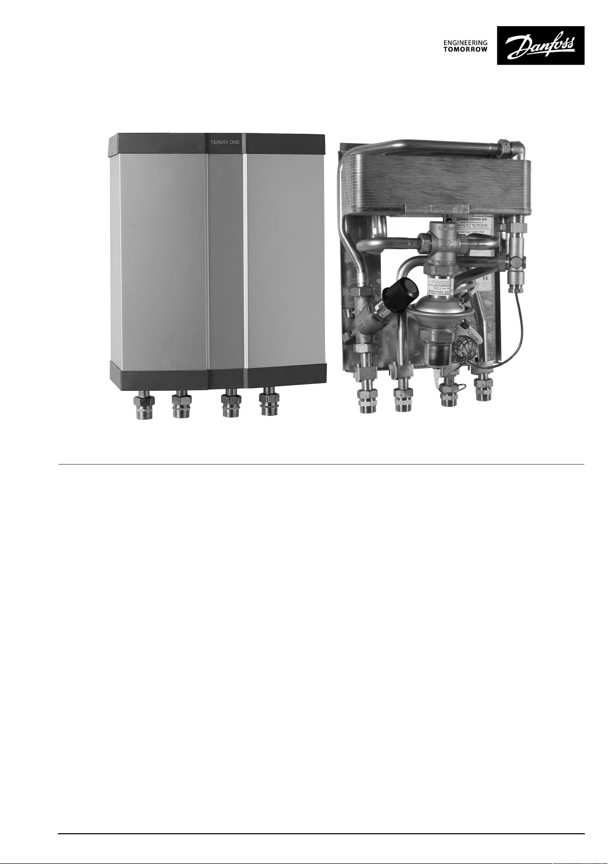
Districtheatingsubstationfordirectheatingand
instantaneousdomestichotwaterwithaself-acting
thermostatic/flowcontroller .Designedforwall-mounting.
Application
TheTermixOneisaninstantaneouswaterheaterfeaturingsuperb
heatextractionandhighperformance.TheTermixOneissuitable
forflats,single-familyhousesaswellasforsmallapartment
buildingswithupto10apartments.Thewaterheaterisavailablein
threesizes,eitherfor1apartment,for1‑4apartmentsorfor5up
to10apartments.TheTermixOneisapplicablefordecentralized
heatingsystems–aswellasfordistrictheatingnetworkswith
summeroperationatlowtemperaturesorchangesindifferential
pressure.TheTermixOneheatexchangercoolsoutthedistrict
heatingwaterveryefficiently,therebycreatingaverygood
operationeconomy.
Domestichotwater(DHW)
Thedomestichotwaterispreparedintheheatexchangerand
thetemperatureisregulatedwithaself-actingthermostatic
controlvalvethatcontrolstheDHWpreparationbyusinga
flow-compensationprinciple.Therapidclosingofthecontrol
valveprotectstheheatexchangeragainstoverheatingandlime
scaleformation.Thecontrolvalveensuresastablehotwater
temperaturebyvaryingloads,flowtemperaturesanddifferential
pressurewithouttheneedforreadjustingthevalve.Theheat
exchangercoolsoutthedistrictheatingwaterveryefficiently,
therebycreatingaverygoodoperatingeconomy.Thecontrol
valvealsoworksasabypasskeepingthehousesupplylineat35°C
duringstandstill.Thisshortensthewaitingperiodsduringsummer
whentheheatingsystemisinreducedoperation.
2|©Danfoss|2018.12
VI.GE.I5.02/LUK38020
Page 3
OperatingGuideTermixOne-Q
3.0Safetynotes
3.1SafetyNotes–general
Thefollowinginstructionsrefertothestandarddesignof
substation.Specialversionsofsubstationsareavailableon
request.
Thisoperatingmanualshouldbereadcarefullybeforeinstallation
andstart-upofthesubstation.Themanufactureracceptsno
liabilityfordamageorfaultsthatresultfromnon-compliancewith
theoperatingmanual.Pleasereadandfollowalltheinstructions
carefullytopreventaccidents,injuryanddamagetoproperty.
Assembly,start-upandmaintenanceworkmustbeperformedby
qualifiedandauthorizedpersonnelonly.
Pleasecomplywiththeinstructionsissuedbythesystem
manufacturerorsystemoperator.
Corrosionprotection
Allpipesandcomponentsaremadeofstainlesssteelandbrass.
Themaximumchloridecompoundsoftheflowmediumshouldnot
behigherthan150mg/l.
Theriskofequipmentcorrosionincreasesconsiderablyifthe
recommendedlevelofpermissiblechloridecompoundsis
exceeded.
Energysource
Thesubstationisdesignedfordistrictheatingastheprimary
sourceofenergy.However,alsootherenergysourcescanbeused
wheretheoperatingconditionsallowitandalwaysarecomparable
todistrictheating.
Application
Thesubstationisdesignedtobeconnectedtothehouse
installationinafrost-freeroom,wherethetemperaturedoesnot
exceed50°Candthehumiditydoesnotexceed60%.Donotcover
orwallupthesubstationorinanyotherwayblocktheentrance
tothestation.
Authorizedpersonnelonly
Assembly,start-upandmaintenanceworkmustbeperformedby
qualifiedandauthorizedpersonnelonly.
Pleaseobserveinstructionscarefully
Toavoidinjurytopersonsanddamagetothedevice,itisabsolutely
necessarytoreadandobservetheseinstructionscarefully.
Warningofhighpressureandtemperature
Beawareoftheinstallation’spermissiblesystempressureand
temperature.
Themaximumtemperatureoftheflowmediuminthesubstationis
110°C.
Themaximumoperatingpressureofthesubstationis10bar.PN16
versionsareavailableonenquiry.
Theriskofpersonsbeinginjuredandequipmentdamagedincreases
considerablyiftherecommendedpermissibleoperatingparameters
areexceeded.
Thesubstationinstallationmustbeequippedwithsafetyvalves,
however,alwaysinaccordancewithlocalregulations.
Choiceofmaterial
Choiceofmaterialsalwaysincompliancewithlocallegislation.
Safetyvalve(s)
Werecommendmountingofsafetyvalve(s),however,alwaysin
compliancewithlocalregulations.
Connection
Thesubstationmustbeequippedwithfeaturesthatensurethat
thesubstationcanbeseparatedfromallenergysources(also
powersupply).
Emergency
Incaseofdangeroraccidents-fire,leaksorotherdangerous
circumstances-interruptallenergysourcestothestationif
possible,andseekexperthelp.
Incaseofdiscolouredorbad-smellingdomestichotwater,closeall
shut-offvalvesonthesubstation,informtheoperatingpersonnel
andcallforexperthelpimmediately.
REACH
AllDanfossA/SproductsfulfilltherequirementsinREACH.
OneoftheobligationsinREACHistoinformcustomersabout
presenceofCandidatelistsubstancesifany,weherebyinform
youaboutonesubstanceonthecandidatelist:Theproduct
containsbrasspartswhichcontainslead(CASno:7439-92-1)ina
concentrationabove0.1%w/w.
Storage
Anystorageofthesubstationwhichmaybenecessarypriorto
installationshouldbeinconditionswhicharedryandheated.
Warningofhotsurface
Thesubstationhasgothotsurfaces,whichcancauseskinburns.
Pleasebeextremelycautiousincloseproximitytothesubstation.
Powerfailurecanresultinthemotorvalvesbeingstuckinopen
position.Thesurfacesofthesubstationcangethot,whichcancause
skinburns.Theballvalvesondistrictheatingsupplyandreturnshould
beclosed.
Warningoftransportdamage
Beforesubstationinstallation,pleasemakesurethatthesubstation
hasnotbeendamagedduringtransport.
IMPORTANT-Tighteningofconnections
Duetovibrationsduringtransportallflangeconnections,screwjoints
andelectricalclampandscrewconnectionsmustbecheckedand
tightenedbeforewaterisaddedtothesystem.Afterwaterhasbeen
addedtothesystemandthesystemhasbeenputintooperation,
re-tightenALLconnections.
VI.GE.I5.02/LUK38020
©Danfoss|2018.12|3
Page 4
OperatingGuideTermixOne-Q
4.0Mounting
4.1Mounting
Installationmustbeincompliancewithlocalstandardsand
regulations.
Districtheating(DH)-Inthefollowingsections,DHreferstothe
heatsourcewhichsuppliesthesubstations.Avarietyofenergy
sources,suchasoil,gasorsolarpower,couldbeusedasthe
primarysupplytoDanfosssubstations.Forthesakeofsimplicity,
DHcanbetakentomeantheprimarysupply.
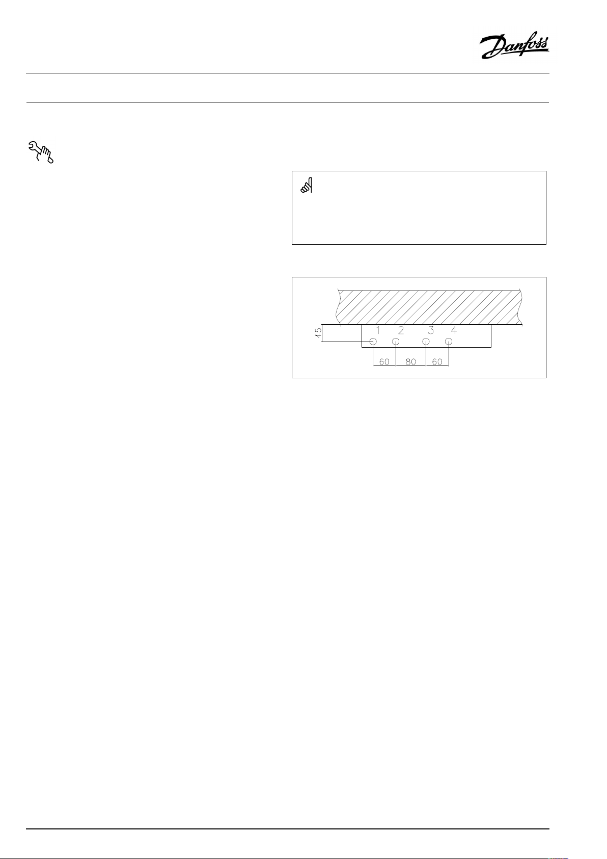
Connections:
1.Domesticcoldwater(DCW)
2.Domestichotwater(DHW)
3.Districtheating(DH)supply
4.Districtheating(DH)return
Connectionsizes:
Authorizedpersonnelonly
Assembly,start-upandmaintenanceworkmustbeperformedby
qualifiedandauthorizedpersonnelonly.
DH:
DCW+DHW:
Dimensions(mm):
Type1+2withoutcover:
H428xW312xD155
Type1+2withcover:
H430xW315xD165
Type3withoutcover:
H468xW312xD155
Type3withcover:
H470xW315xD165
Weight(approx.):10–12kg
G¾”(int.thread)
G¾”(int.thread)
Thepipeplacementcandeviatefromtheshowndrawing.Pleasenote
themarkingsonthestation.
4|©Danfoss|2018.12
VI.GE.I5.02/LUK38020
Page 5
OperatingGuideTermixOne-Q
4.1.1Installation
Mounting:
Adequatespace
Pleaseallowadequatespacearoundthesubstationformounting
andmaintenancepurposes.
Orientation
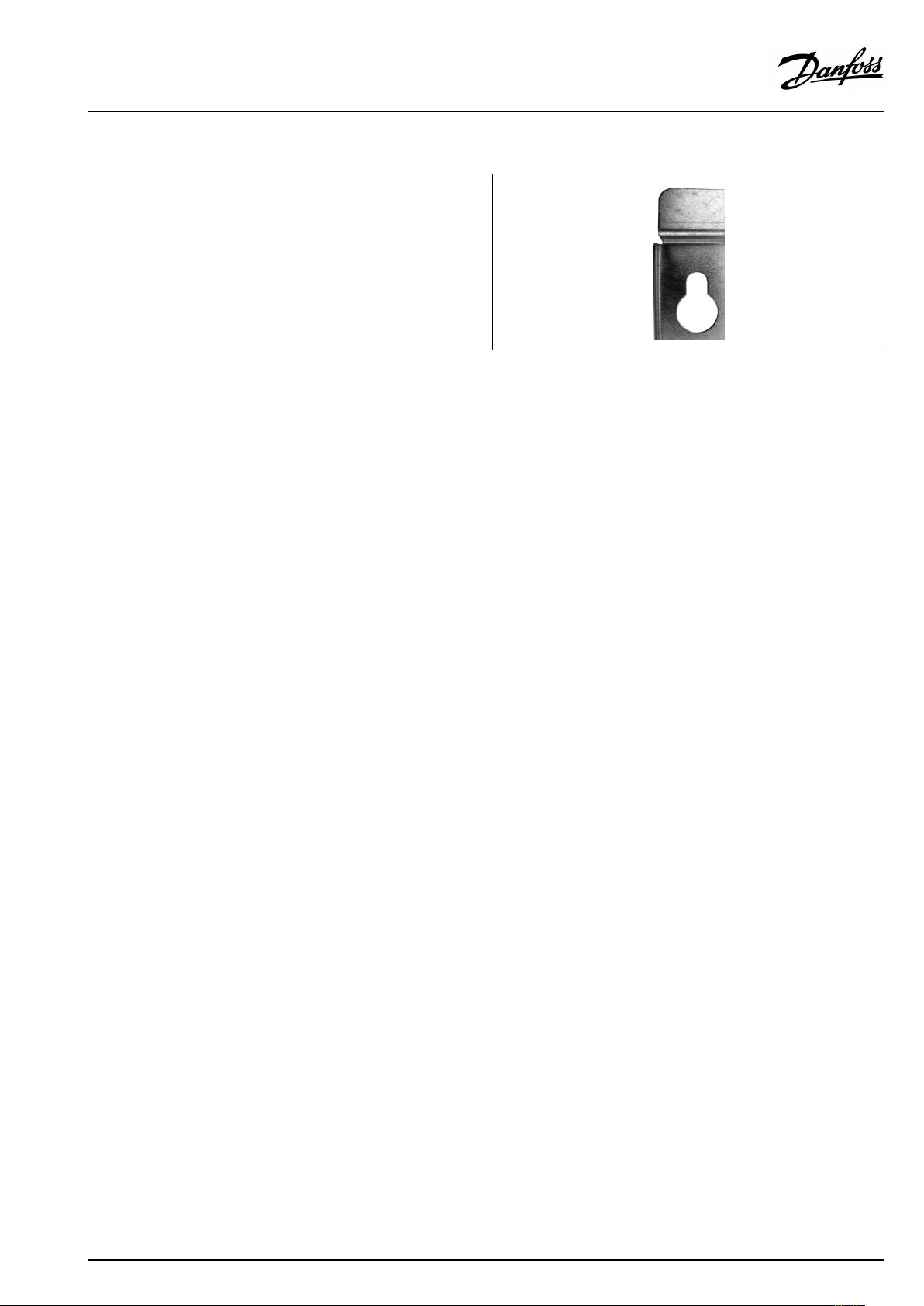
Thestationmustbemountedsothatcomponents,keyholes
andlabelsareplacedcorrectly.Ifyouwishtomountthestation
differentlypleasecontactyoursupplier.
Drillings
Wheresubstationsaretobewall-mounted,drillingsareprovided
inthebackmountingplate.Floormountedunitshavesupport.
Labelling
Eachconnectiononthesubstationislabelled.
Beforeinstallation:
Cleanandrinse
Priortoinstallation,allsubstationpipesandconnectionsshouldbe
cleanedandrinsed.
Keyholeformounting.
Tightening
Duetovibrationduringtransport,allsubstationconnectionsmust
becheckedandtightenedbeforeinstallation.
Unusedconnections
Unusedconnectionsandshut-offvalvesmustbesealedwitha
plug.Shouldtheplugsrequireremoval,thismustonlybedoneby
anauthorizedservicetechnician.
Installation:
Strainer
Ifastrainerissuppliedwiththestationitmustbefittedaccording
toschematicdiagram.Pleasenotethatthestrainermaybe
suppliedloose.
Connections
Internalinstallationanddistrictheatingpipesconnectionsmustbe
madeusingthreaded,flangedorweldedconnections.
VI.GE.I5.02/LUK38020
©Danfoss|2018.12|5
Page 6

OperatingGuideTermixOne-Q
5.0Design
5.1Design
Yoursubstationmightlookdifferentthanthesubstationshown.
Designdescription
B
Heatexchanger ,DHW
8
Flow-compensatedthermostaticvalve,DHW
32
Controlvalve,DHW
6|©Danfoss|2018.12
VI.GE.I5.02/LUK38020
Page 7

OperatingGuideTermixOne-Q
5.2Schematicdiagram
Supply
Return
Supply
DH
DH
DH
DHW
DCW
DHW
DH
Return
Yoursubstationmightlookdifferentthantheschematicdiagramshown.
Firstdiagram:T ermixOne-Q-withGTU.
Seconddiagram:T ermixOne-Q-withsafetyvalve.
Schematicdescription
B
Beatexchanger,DHW
4
Safetyvalve
8
Flow-compensatedthemostaticvalve
DHW:DomesticHotWater
DCW:
DHSupply:DistrictHeatingSupply
DHReturn:DistrictHeatingReturn
DomesticColdWater
21
Tobeorderedseparately
32
Controlvalve
62
GTUPressureequalizer
DCW
VI.GE.I5.02/LUK38020
©Danfoss|2018.12|7
Page 8

OperatingGuideTermixOne-Q
5.2.1Technicalparameters
Technicalparameters
Nominalpressure:
Max.DHsupplytemperature:
Min.DCWstaticpressure:
Brazingmaterial(HEX):
Heatexchangerstestpressure:30bar
Soundlevel:≤55dB
PN16
110°C
0.5bar
Copper
8|©Danfoss|2018.12
VI.GE.I5.02/LUK38020
Page 9

OperatingGuideTermixOne-Q
6.0Controls
6.1DHWtemperaturecontrol
DHWtemperaturecontrol
TherearevarioustypesofDHWtemperaturecontrolusedin
Danfosssubstations.
DHWtemperatureshouldbeadjustedto45-50°C,asthisprovides
optimalutilisationofDHwater.AtDHWtemperaturesabove55°C,
thepossibilityoflimescaledepositsincreasessignificantly.
6.1.1AVTQcontroller(20–60°)
AVTQisaself-actingflow-compensatedtemperaturecontroller.It
hasapermanentno-load(idle)temperaturesettingofabout35°C.
TheAVTBoperatesatitsbestatDHsupplytemperaturesofupto
90°C.
Thermostaticcontrol
DHWtemperatureisadjustedasfollows:
Toincreasetemperature,turnthehandleonthethermostatic
controllertoselectahighernumber.
Todecreasetemperature,turnthehandleonthethermostatic
controllertoselectalowernumber.
VI.GE.I5.02/LUK38020
©Danfoss|2018.12|9
Page 10

OperatingGuideTermixOne-Q
6.2Other
6.2.1Safetyvalve
Thepurposeofthesafetyvalveistoprotectthesubstationfrom
excessivepressure.
Theblow-offpipefromthesafetyvalvemustnotbeclosed.The
blow-offpipeoutletshouldbeplacedsothatitdischargesfreely
anditispossibletoobserveanydrippingfromthesafetyvalve.
Itisrecommendedtochecktheoperationofsafetyvalvesat
intervalsof6months.Thisisdonebyturningthevalveheadin
directionindicated.
6.2.2Strainer
Strainersshouldbecleanedregularlybyauthorizedpersonnel.The
frequencyofcleaningwoulddependonoperatingconditionsand
themanufacturer’sinstructions.
6.2.3GTUPressureEqualizer
TheGTUPressureEqualizerabsorbstheexpansiononthe
secondarysideoftheTermixwaterheatersandcanbeusedasa
substitutetothesafetyvalve.
Furthermorethepressureequalizerabsorbsapossibleincreasein
pressure,soadischargeoutletisomitted.
TheGTUPressureEqualizermaynotbeappliedinsystemswithhot
watercirculation.
10|©Danfoss|2018.12
VI.GE.I5.02/LUK38020
Page 11

OperatingGuideTermixOne-Q
6.3Maintenance
Thesubstationrequireslittlemonitoring,apartfromroutine
checks.Itisrecommendedtoreadtheenergymeteratregular
intervals,andtowritedownthemeterreadings.
RegularinspectionsofthesubstationaccordingtothisInstruction
arerecommended,whichshouldinclude:
Strainers
Cleaningofstrainers.
Meters
Checkingofalloperatingparameterssuchasmeterreadings.
Temperatures
Checkingofalltemperatures,suchasDHsupplytemperatureand
DHWtemperature.
Connections
Checkingallconnectionsforleakages.
Safetyvalves
Theoperationofthesafetyvalvesshouldbecheckedbyturning
thevalveheadintheindicateddirection.
Venting
Checkingthatthesystemisthoroughlyvented.
Authorizedpersonnelonly
Assembly,start-upandmaintenanceworkmustbeperformedby
qualifiedandauthorizedpersonnelonly.
Inspectionsshouldbecarriedoutminimumeverytwoyears.
SparepartscanbeorderedfromDanfoss.Pleaseensurethatany
enquiryincludesthesubstationserialnumber.
VI.GE.I5.02/LUK38020
©Danfoss|2018.12|11
Page 12

OperatingGuideTermixOne-Q
7.0Troubleshooting
7.1Troubleshootingingeneral
Intheeventofoperatingdisturbances,thefollowingbasicfeatures
shouldbecheckedbeforecarryingoutactualtroubleshooting:
•thesubstationisconnectedtoelectricity,
•thestrainerontheDHsupplypipeisclean,
•thesupplytemperatureoftheDHisatthenormallevel
(summer,atleast60°C-winter,atleast70°C),
•thedifferentialpressureisequaltoorhigherthanthenormal
(local)differentialpressureintheDHnetwork–ifindoubt,ask
theDHplantsupervisor,
•pressureonthesystem-checktheHEpressuregauge.
Authorizedpersonnelonly
Assembly,start-upandmaintenanceworkmustbeperformedby
qualifiedandauthorizedpersonnelonly.
12|©Danfoss|2018.12
VI.GE.I5.02/LUK38020
Page 13

OperatingGuideTermixOne-Q
7.2TroubleshootingDHW
ProblemPossiblecauseSolution
ToolittleornoDHW.
Taptemperaturetoohigh;DHWtapload
toohigh.
Temperaturedropduringtapping.
Thermostaticcontrolvalvedoesnotclose
Strainerinsupplyorreturnlineclogged.Cleanstrainer(s).
DHWcirculationpumpoutoforderorwith
toolowsetting.
Defectiveorcloggednon-returnvalve.
Noelectricity.Check.
Wrongsettingofautomaticcontrols,ifany.Toadjustanelectroniccontrollerfor
Scalingoftheplateheatexchanger.
Defectivemotorizedvalve.Check(usemanualfunction)–replace.
Defectivetemperaturesensors.
Defectivecontroller.
DCWisbeingmixedwiththeDHW,e.g.ina
defectivethermostaticmixingvalve.
Defectiveorcloggednon-returnvalveon
circulationvalve.
Thermostaticvalveadjustedtoatoohigh
level.
Scalingoftheplateheatexchanger.
LargerDHWflowthanthesubstationhas
beendesignedfor.
TemperaturedifferencebetweenDH
supplyandDHWsetpointtoolow.
Checkcirculationpump.
Replace–clean.
DHW,pls.noteenclosedinstructionsfor
electroniccontroller.
Replace–rinseout.
Check–replace.
Check–replace.
Check–replace. Hotwaterinsometapsbutnotinall.
Replace–clean.
Check–set.
Replace–rinseout.
ReduceDHWflow.
Lowerthesetpointtemperatureorincrease
theDHsupplytemperature.
VI.GE.I5.02/LUK38020
©Danfoss|2018.12|13
Page 14

OperatingGuideTermixOne-Q
7.3Disposal
Disposal
Thisproductshouldbedismantledanditscomponents
sorted,ifpossible,invariousgroupsbeforerecycling
ordisposal.
Alwaysfollowthelocaldisposalregulations.
14|©Danfoss|2018.12
VI.GE.I5.02/LUK38020
Page 15

OperatingGuideTermixOne-Q
8.0Declaration
8.1Declarationofconformity
Category0withoutelectricalequipment
VI.GE.I5.02/LUK38020
©Danfoss|2018.12|15
Page 16

OperatingGuideTermixOne-Q
16|©Danfoss|2018.12
VI.GE.I5.02/LUK38020
 Loading...